EP3325832B1 - Procédé de fabrication sans enlèvement de copeaux d'une bague de palier pour un palier à roulement et palier à roulement comprenant la bague de palier - Google Patents
Procédé de fabrication sans enlèvement de copeaux d'une bague de palier pour un palier à roulement et palier à roulement comprenant la bague de palier Download PDFInfo
- Publication number
- EP3325832B1 EP3325832B1 EP16738060.9A EP16738060A EP3325832B1 EP 3325832 B1 EP3325832 B1 EP 3325832B1 EP 16738060 A EP16738060 A EP 16738060A EP 3325832 B1 EP3325832 B1 EP 3325832B1
- Authority
- EP
- European Patent Office
- Prior art keywords
- bearing ring
- bearing
- contour
- surface profile
- raceway
- Prior art date
- Legal status (The legal status is an assumption and is not a legal conclusion. Google has not performed a legal analysis and makes no representation as to the accuracy of the status listed.)
- Not-in-force
Links
- 238000005096 rolling process Methods 0.000 title claims description 57
- 238000000034 method Methods 0.000 title claims description 40
- 238000004519 manufacturing process Methods 0.000 title claims description 24
- 238000005520 cutting process Methods 0.000 title description 3
- 238000000641 cold extrusion Methods 0.000 claims description 13
- 239000011324 bead Substances 0.000 claims description 7
- 238000007373 indentation Methods 0.000 description 5
- 238000005516 engineering process Methods 0.000 description 3
- 238000000465 moulding Methods 0.000 description 3
- 238000001953 recrystallisation Methods 0.000 description 3
- 239000011265 semifinished product Substances 0.000 description 3
- 229910000831 Steel Inorganic materials 0.000 description 2
- 230000000694 effects Effects 0.000 description 2
- 238000002347 injection Methods 0.000 description 2
- 239000007924 injection Substances 0.000 description 2
- 238000003754 machining Methods 0.000 description 2
- 239000000463 material Substances 0.000 description 2
- 239000002184 metal Substances 0.000 description 2
- 239000010959 steel Substances 0.000 description 2
- 238000005452 bending Methods 0.000 description 1
- 230000001419 dependent effect Effects 0.000 description 1
- 238000011161 development Methods 0.000 description 1
- 230000018109 developmental process Effects 0.000 description 1
- 238000004049 embossing Methods 0.000 description 1
- 238000001125 extrusion Methods 0.000 description 1
- 239000012467 final product Substances 0.000 description 1
- 238000004080 punching Methods 0.000 description 1
- 238000000926 separation method Methods 0.000 description 1
- 238000007493 shaping process Methods 0.000 description 1
- 239000007787 solid Substances 0.000 description 1
- 239000011343 solid material Substances 0.000 description 1
- 238000005482 strain hardening Methods 0.000 description 1
Images


Classifications
-
- B—PERFORMING OPERATIONS; TRANSPORTING
- B21—MECHANICAL METAL-WORKING WITHOUT ESSENTIALLY REMOVING MATERIAL; PUNCHING METAL
- B21J—FORGING; HAMMERING; PRESSING METAL; RIVETING; FORGE FURNACES
- B21J5/00—Methods for forging, hammering, or pressing; Special equipment or accessories therefor
- B21J5/06—Methods for forging, hammering, or pressing; Special equipment or accessories therefor for performing particular operations
- B21J5/12—Forming profiles on internal or external surfaces
-
- F—MECHANICAL ENGINEERING; LIGHTING; HEATING; WEAPONS; BLASTING
- F16—ENGINEERING ELEMENTS AND UNITS; GENERAL MEASURES FOR PRODUCING AND MAINTAINING EFFECTIVE FUNCTIONING OF MACHINES OR INSTALLATIONS; THERMAL INSULATION IN GENERAL
- F16C—SHAFTS; FLEXIBLE SHAFTS; ELEMENTS OR CRANKSHAFT MECHANISMS; ROTARY BODIES OTHER THAN GEARING ELEMENTS; BEARINGS
- F16C33/00—Parts of bearings; Special methods for making bearings or parts thereof
- F16C33/30—Parts of ball or roller bearings
- F16C33/58—Raceways; Race rings
- F16C33/64—Special methods of manufacture
-
- F—MECHANICAL ENGINEERING; LIGHTING; HEATING; WEAPONS; BLASTING
- F16—ENGINEERING ELEMENTS AND UNITS; GENERAL MEASURES FOR PRODUCING AND MAINTAINING EFFECTIVE FUNCTIONING OF MACHINES OR INSTALLATIONS; THERMAL INSULATION IN GENERAL
- F16C—SHAFTS; FLEXIBLE SHAFTS; ELEMENTS OR CRANKSHAFT MECHANISMS; ROTARY BODIES OTHER THAN GEARING ELEMENTS; BEARINGS
- F16C19/00—Bearings with rolling contact, for exclusively rotary movement
- F16C19/02—Bearings with rolling contact, for exclusively rotary movement with bearing balls essentially of the same size in one or more circular rows
- F16C19/04—Bearings with rolling contact, for exclusively rotary movement with bearing balls essentially of the same size in one or more circular rows for radial load mainly
- F16C19/06—Bearings with rolling contact, for exclusively rotary movement with bearing balls essentially of the same size in one or more circular rows for radial load mainly with a single row or balls
-
- B—PERFORMING OPERATIONS; TRANSPORTING
- B21—MECHANICAL METAL-WORKING WITHOUT ESSENTIALLY REMOVING MATERIAL; PUNCHING METAL
- B21D—WORKING OR PROCESSING OF SHEET METAL OR METAL TUBES, RODS OR PROFILES WITHOUT ESSENTIALLY REMOVING MATERIAL; PUNCHING METAL
- B21D53/00—Making other particular articles
- B21D53/10—Making other particular articles parts of bearings; sleeves; valve seats or the like
-
- B—PERFORMING OPERATIONS; TRANSPORTING
- B21—MECHANICAL METAL-WORKING WITHOUT ESSENTIALLY REMOVING MATERIAL; PUNCHING METAL
- B21K—MAKING FORGED OR PRESSED METAL PRODUCTS, e.g. HORSE-SHOES, RIVETS, BOLTS OR WHEELS
- B21K1/00—Making machine elements
- B21K1/04—Making machine elements ball-races or sliding bearing races
-
- F—MECHANICAL ENGINEERING; LIGHTING; HEATING; WEAPONS; BLASTING
- F16—ENGINEERING ELEMENTS AND UNITS; GENERAL MEASURES FOR PRODUCING AND MAINTAINING EFFECTIVE FUNCTIONING OF MACHINES OR INSTALLATIONS; THERMAL INSULATION IN GENERAL
- F16C—SHAFTS; FLEXIBLE SHAFTS; ELEMENTS OR CRANKSHAFT MECHANISMS; ROTARY BODIES OTHER THAN GEARING ELEMENTS; BEARINGS
- F16C2220/00—Shaping
- F16C2220/40—Shaping by deformation without removing material
- F16C2220/42—Shaping by deformation without removing material by working of thin-walled material such as sheet or tube
-
- F—MECHANICAL ENGINEERING; LIGHTING; HEATING; WEAPONS; BLASTING
- F16—ENGINEERING ELEMENTS AND UNITS; GENERAL MEASURES FOR PRODUCING AND MAINTAINING EFFECTIVE FUNCTIONING OF MACHINES OR INSTALLATIONS; THERMAL INSULATION IN GENERAL
- F16C—SHAFTS; FLEXIBLE SHAFTS; ELEMENTS OR CRANKSHAFT MECHANISMS; ROTARY BODIES OTHER THAN GEARING ELEMENTS; BEARINGS
- F16C2220/00—Shaping
- F16C2220/40—Shaping by deformation without removing material
- F16C2220/44—Shaping by deformation without removing material by rolling
-
- F—MECHANICAL ENGINEERING; LIGHTING; HEATING; WEAPONS; BLASTING
- F16—ENGINEERING ELEMENTS AND UNITS; GENERAL MEASURES FOR PRODUCING AND MAINTAINING EFFECTIVE FUNCTIONING OF MACHINES OR INSTALLATIONS; THERMAL INSULATION IN GENERAL
- F16C—SHAFTS; FLEXIBLE SHAFTS; ELEMENTS OR CRANKSHAFT MECHANISMS; ROTARY BODIES OTHER THAN GEARING ELEMENTS; BEARINGS
- F16C2220/00—Shaping
- F16C2220/40—Shaping by deformation without removing material
- F16C2220/46—Shaping by deformation without removing material by forging
-
- F—MECHANICAL ENGINEERING; LIGHTING; HEATING; WEAPONS; BLASTING
- F16—ENGINEERING ELEMENTS AND UNITS; GENERAL MEASURES FOR PRODUCING AND MAINTAINING EFFECTIVE FUNCTIONING OF MACHINES OR INSTALLATIONS; THERMAL INSULATION IN GENERAL
- F16C—SHAFTS; FLEXIBLE SHAFTS; ELEMENTS OR CRANKSHAFT MECHANISMS; ROTARY BODIES OTHER THAN GEARING ELEMENTS; BEARINGS
- F16C2220/00—Shaping
- F16C2220/80—Shaping by separating parts, e.g. by severing, cracking
- F16C2220/84—Shaping by separating parts, e.g. by severing, cracking by perforating; by punching; by stamping-out
Definitions
- the invention relates to a method for manufacturing a bearing ring for a rolling bearing, wherein the bearing ring has a raceway side with at least one raceway and an abutment side for abutment with a support structure and wherein the bearing ring defines a major axis of the rolling bearing, wherein the bearing ring on the contact side at least one contour portion and wherein the bearing ring is made by forming from a bearing ring blank.
- the invention also relates to a rolling bearing having at least one bearing ring, wherein the bearing ring is made by the method.
- Rolling element bearings have, in many designs, an inner ring, an outer ring and a plurality of rolling elements disposed rollingly between the inner ring and the outer ring.
- the inner ring and the outer ring are very often machined from solid material.
- Such solid rings have the advantage of high rigidity and a low manufacturing tolerance.
- the production of massive rings is expensive due to the required semi-finished product and due to the manufacturing process.
- the document discloses DE 10 2007 027 216 A1 , which is probably the closest prior art, a method for chipless production of a rolling bearing.
- the method it is provided that two ring sections are separated from a sheet, but which remain connected to each other via support webs.
- indentations in the form of annular grooves are introduced on one end face of the ring sections.
- a deep drawing takes place, during the deep-drawing process, the annular grooves to raceways of the bearing and in addition the rolling elements are inserted.
- the shape of the raceways is determined by the impressions before the deep-drawing process.
- the DE 19 38 165 A1 describes a production of rolling bearing rings made of flat steel.
- circular rings are punched out of blanks and subsequently transferred by pulling in a cylindrical shape.
- a rolling groove for rolling elements can be pressed in advance in such a circular ring.
- the subject of the invention is thus a method for manufacturing a bearing ring for a rolling bearing.
- the rolling bearing is designed in particular as a radial rolling bearing.
- the bearing ring may be formed as an inner ring or as an outer ring. In addition to this, both the inner ring and the outer ring can be manufactured according to the invention.
- the bearing ring made of metal, in particular made of steel.
- the rolling bearing can have any type of rolling elements, in particular balls or rollers. However, it is preferred that the rolling elements are formed as balls.
- the rolling bearing is a deep groove ball bearing, in particular a single row roller bearing.
- the bearing ring has a raceway side with at least one raceway for the rolling elements. Furthermore, the bearing ring has an abutment side for bearing against a support structure, wherein the bearing ring has at least one contour section on the abutment side. In the event that the bearing ring as an inner ring is formed, the raceway side has radially outward and the plant side radially inward. If the bearing ring is formed as an outer ring, the raceway side has radially inward and the plant side to the outside.
- the bearing ring can, for example, optionally be plugged into a recess as a support structure or pushed onto an axle or shaft as a support structure.
- the bearing ring defines a major axis of the rolling bearing.
- the bearing ring defines the main axis by the self-rotation or by the movement of the rolling rolling elements on the bearing ring.
- the raceway side and / or the contact side is formed as a cylinder jacket surface, in which the areas described below are incorporated.
- it is a straight cylindrical surface which is aligned coaxially and / or concentrically with the main axis.
- a method step of the method according to the invention is that a bearing ring blank is formed to produce the bearing ring.
- the inventive method comprises at least the forming step for transferring the bearing ring blank in the bearing ring.
- the bearing ring blank before forming has a surface profile which is formed in the bearing ring blank, wherein the surface profile forms after forming at least one contour portion in the contact side of the bearing ring.
- the surface profile is preferably introduced by forming technology in the bearing ring blank.
- the surface profile is already produced, for example, as an embossing or, in the case of deeper surface profiles, by extrusion, in particular cold extrusion.
- the surface profile may be formed, in particular such that it projects beyond the abutment side, in particular over the cylinder jacket surface.
- a mixed form of the molded and the molded surface profile can be provided.
- the contour section forms a main axis partially, partially or completely encircling profile.
- the contour section is formed as a groove section and thus as one, the main axis partially, partially or completely circumferential groove. So it is within the scope of the invention that the contour section extends only in an angular segment about the main axis. It can also be provided that the contour section is aligned in the axial direction. It is also possible that several contour sections are introduced. However, it is particularly preferred that the contour section forms a completely circumferential, in particular in the circumferential direction around the main axis closed, groove.
- the groove may be formed, for example, as a retaining groove for mounting or as an oil circulation groove.
- the contour section can be used for any functional structure on the support structure.
- the contour section is formed as an undercut contour, in particular as an undercut.
- the undercut contour is formed with respect to both axial directions to the major axis.
- This embodiment again emphasizes the inventive idea to introduce the surface profile already in the bearing ring blank.
- the surfaces which later forms the contact side of the bearing ring, freely accessible, so any structure introduced in particular, in particular, can be imprinted. Only after the forming process, the surface profile is arranged as the contour portion so that it forms the undercut contour.
- the inventive method opens a cost-effective introduction of the contour portion at a position that is difficult to achieve during the forming step manufacturing technology.
- the contour section is formed as a survey contour, which projects beyond the contact side.
- the contour section is not introduced by the tool, which effects the forming, but has already been introduced into the bearing ring blank as the surface profile.
- the forming is particularly designed as a folding or bending of the shape of the bearing ring blank in the bearing ring.
- the undercut contour is formed as one or more completely, partially or partially circumferential groove.
- the undercut contour may be formed as a pocket, depression, corrugation, etc.
- this may be formed as a bead, in particular web, completely or partially or in sections, as one or more hills, etc.
- a contour depth of the undercut contour and / or a contour height of the elevation contour are formed larger than 0.5 mm.
- the contour height or contour depth is measured with respect to a cylinder jacket surface which is defined by the contact side.
- the forming is designed as a cold forming, in particular cold extrusion.
- the temperature in the workpiece in this case in the bearing ring blank or in the bearing ring, is lower than the recrystallization temperature of the base material of the workpiece.
- the cold forming of the bearing ring blank at ambient or room temperature, preferably at a temperature of less than 50 degrees, fed to the forming process.
- higher temperatures due to the forming work in the bearing ring blank or in the resulting bearing ring occur, but also the higher temperatures are below the recrystallization temperature of the base material. It is advantageous that by forming, in particular the cold forming, surface tensions are generated in the bearing ring, which lead to an increase in performance.
- the bearing ring blank is formed as an annular disc, wherein the surface profile is introduced or is forming technology on a first end face of the annular disc.
- the annular disc is preferably separated from a sheet having a thickness of less than 10 millimeters and / or preferably greater than 2 millimeters. It is possible that first the annular disc is cut out and then the surface profile is introduced. However, it is also possible that first the surface profile is introduced and then the annular disc is separated with the surface profile.
- the annular disc has a further surface profile on a second end face.
- the second end face is arranged opposite to the first end face.
- the further surface profile is designed so that this forms the raceway after forming.
- the further surface profile is formed as a further undercut contour, in particular formed.
- the further surface profile is formed as an annular groove. This results after forming the bearing ring blank into the bearing ring in a raceway, in particular groove raceway, for balls as rolling elements.
- the final shape of the contour section in particular a Nutenabitess, by the surface profile, in particular the indentation and / or Anformung, and the forming and / or the final shape of the track by the further surface profile, in particular the further molding and forming educated.
- the cross-sectional profile of the contour section is preferably formed by the cross-sectional profile of the surface profile in cooperation with the forming.
- the cross-sectional profile of the track is preferably formed by the cross-sectional profile of the further surface profile in cooperation with the forming.
- the method according to the invention makes it possible to produce close-net-shape production or final shape production (net-shape-manufacturing), in particular of the raceway and / or of the contour section.
- the rolling bearing on an outer ring and an inner ring wherein the outer ring and / or the inner ring is formed as the bearing ring or are. It is particularly preferred that a bearing ring blank of the inner ring is made of an inner region of a sheet metal section for a bearing ring blank of the outer ring. In this way, the rolling bearing can be produced very inexpensively with the inventively manufactured at least one bearing ring.
- the bearing ring can be case hardened or through hardened.
- Another object of the invention relates to a rolling bearing with at least one bearing ring, which is made according to the invention according to the invention.
- the rolling bearing is preferably designed as described above.
- the rolling bearing according to the invention comprises at least one bearing ring, wherein the bearing ring is made by the method according to the invention, wherein the bearing ring has a raceway side, wherein on the raceway side at least one raceway for rolling elements is arranged, wherein the bearing ring has a contact side for bearing the bearing ring to a support structure , and, wherein the bearing ring is made by forming, in particular cold extrusion from a bearing ring blank, wherein the bearing ring on the plant side has at least one contour portion, wherein the contour portion is formed by a surface profile which has been formed in the bearing ring blank.
- the bearing ring has a raceway side, wherein one or more raceways for rolling elements of the rolling bearing is / are arranged on the raceway side. Furthermore, the bearing ring has an abutment side for bearing the bearing ring on a support structure, such as an axle or shaft for the inner ring or a housing for the outer ring on.
- the bearing ring is made by a forming process, in particular by cold extrusion, from a bearing ring blank.
- Such a rolling bearing is particularly inexpensive to produce.
- the bearing rings of the rolling bearing according to the invention have no machined surfaces.
- we made in the area of the running surfaces and the contour portion of the bearing rings no machining reworking, but the surfaces present after forming surfaces used directly in the rolling bearing.
- the costs for the rolling bearing are much lower than in conventional bearings.
- the bearing ring has at least one contour section on the contact side, wherein the contour section is formed by a surface profile in the bearing ring blank.
- the contour portion has as the Surface profile already exists before the forming process.
- the bearing ring blank is formed as an annular disc, which is formed into a sleeve.
- the first end face of the annular disc forms an outer lateral surface and the second end side of the annular disc forms an inner lateral surface of the bearing ring.
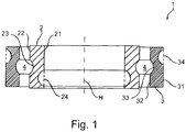
- FIG. 1 shows a schematic longitudinal sectional view of a rolling bearing 1 as an embodiment of the invention.
- the rolling bearing 1 has an inner ring 2 and an outer ring 3, wherein the outer ring 3 is arranged coaxially and concentrically with the inner ring 2.
- the inner ring 2 and the outer ring 3 each form one Bearing Ring of the Rolling Bearing 1.
- the rolling bearing 1 has a major axis H, which is defined by a rotational axis of the inner ring 2 and / or the outer ring 3.
- the rolling bearing 1 is formed as a deep groove ball bearing with a groove 4 for balls as rolling elements. However, the representation of the rolling elements has been omitted here.
- the rolling bearing 1 is realized as a radial rolling bearing. In principle, it is possible that - as shown - the rolling bearing 1 is formed in a single row, alternatively, the rolling bearing 1 may also be formed multi-row.
- the inner ring 2 has an abutment side 21 and a raceway side 22.
- the abutment side 21 is directed radially inward and formed in the coarse form as a straight cylindrical surface, which is aligned coaxially and concentrically to the main axis H.
- the raceway side 22 is aligned coaxially and concentrically to the contact side 21 and formed in the coarse form as a straight cylindrical surface.
- the contact surface 21 serves to rest on a support structure, such as on an axis or on a shaft.
- the outer ring 3 has an abutment side 31 and a raceway side 32.
- the contact side 31 and the raceway side 32 are each formed in the coarse form as cylinder jacket surfaces, which are aligned coaxially and / or concentrically with each other and / or to the main axis H.
- the abutment side 31 serves to bear against a support structure, such as a recess or bore in a housing.
- raceway 23 and 33 are formed, which together form the groove 4.
- the raceways 23 and 33 form recesses in the cylinder jacket surface of the raceway side 22 of the inner ring 2 and in the raceway side 32 of the outer ring third
- the circumferential groove is in relation to one or both axial directions to the main axis H formed as an undercut contour.
- the circumferential groove is located in an inner region of the contact side 21 of the inner ring 2.
- a further groove is introduced as a contour section 34 in the contact side 31 of the outer ring 3.
- the further groove is arranged in an inner region of the contact side 31 of the outer ring 3.
- the further groove also forms an undercut contour with respect to the main axis H in the axial directions.
- the contour sections 24 and / or 34 may be e.g. be formed as a retaining groove or as an oil circulation groove.
- the production of the outer ring 3 as one of the bearing rings of the rolling bearing 1 is in the FIG. 2 shown in longitudinal steps in different steps:
- a step I a blank 5 is separated from a sheet, in particular punched out.
- a step II a central part 6 is cut off from the blank 5, in particular punched out, so that an annular disc 35 is formed as a bearing ring blank 36.
- a step III is on a first end face 37, which in the FIG. 2 is directed downwards, a surface profile 38 in the form of a main axis H circumferential annular groove introduced as a molding, in particular molded, embossed in particular.
- a further surface profile 310 is introduced on a second end face 39, in particular formed as a recess, impressed in particular, which is likewise designed as a circumferential annular groove.
- the bearing ring blank 36 is reshaped, wherein the forming as a cold forming, in particular cold extrusion is formed.
- the bearing ring blank 36 is not heated and / or reshaped at ambient temperature or room temperature. It is particularly provided that the deformation takes place at a temperature below the recrystallization temperature of the sheet.
- the bearing ring blank 36 embodied as an annular disc 35 is formed into a sleeve into which the track 33 is already introduced on the basis of the further surface profile 310 and a contour section 34 in the form of a groove based on the surface profile 38 FIG. 1 ,
- the shape of the track 33 and the further groove by the molding in the previous step, in particular the step III, and the forming in the step IV and in particular without further shaping action takes place.
- the surface of the track 33 corresponds to the surface of the further surface profile 310, in particular not machined, and / or the surface of the further groove to the surface of the surface profile 38.
- a blank 8 is separated from a sheet 7.
- the middle part 6 from the previously described method for forming the outer ring 3 according to FIG. 2 used.
- the inner ring 2 and the outer ring 3 can be made in a mother-child production from the same area of a sheet 7.
- a further annular disk 25 is generated by a separation, in particular punching of a central part 9.
- the annular disc 25 forms the main body for a bearing ring blank 26 for the inner ring. 2
- a surface profile 28 is formed, in particular embossed. Furthermore, a further surface profile 210 is formed on the second end face 29, especially impressed.
- the surface profile 28 later forms the contour portion 24 in the form of a groove, the further surface profile 210 later forms the raceway 23 of the inner ring 2.
- the surface profiles 28 and 210 are each formed as annular grooves.
- a step IVa and IVb there is a forming process which is designed as a cold forming process, in particular a cold extrusion, and wherein the annular disc 25 is formed as the bearing ring blank 26 in the inner ring 2 or folded.
- the raceway 23 is formed on the raceway side 22 of the inner ring 2 and the contour portion 24 on the contact side 21 of the inner ring 2.
- FIGS. 4 a - d each show a bearing ring blank 26 and 36 with a surface profile 28 and 38 and the resulting bearing ring 2 and 3 with the contour section 24 and 34.
- a plan view of a bearing ring blank 26 and 36 and the right side of each illustration shows a section through the bearing ring 2 or 3 formed therefrom.
- FIG. 4a That's how it shows FIG. 4a on the right side an inner ring 2 with a contour portion 24 on the contact side 21, wherein the contour portion 24 as a plurality in the circumferential direction around the main axis H distributed depressions 211 and thus formed as an undercut contour.
- the recesses 210 are shown on the contact side 21 in the illustrated sectional plane.
- An illustration of the further existing recesses 212 on the contact side 21 has been dispensed with in view of the clarity.
- On the left side of the bearing ring blank 26 is shown, which has on the first end face 27 has a surface profile 28 which is formed as a plurality of recesses 212 arranged in a concentric circle.
- the recesses 212 have a contour depth h1 greater than 0.5 mm.
- the inner ring 2 is formed from the bearing ring blank 26 by cold forming, in particular cold extrusion.
- FIG. 4b shows - in the same representation as the FIG. 4a -
- On the left side of the bearing ring blank 36 is shown, which has on the first end face 37 has a surface profile 38 which is formed as a plurality in a concentric circle recesses 312.
- the recesses 312 have a contour depth h1 greater than 0.5 mm.
- the outer ring 3 is formed from the bearing ring blank 36 by cold forming, in particular cold extrusion.
- FIG. 4c is - in the same representation as in the FIGS. 4a, 4b -
- An outer ring 3 is shown, which in contrast to the embodiment in the FIG. 4b Increases 313 carries as a contour portion 34 and thus implements a survey contour with a contour height h2 of at least 0.5 mm.
- the bearing blank 36 has elevations 314 as a surface profile 38, which are distributed concentrically to a center of the bearing blank 36.
- the elevations 314 are formed, in particular, by injection of plastic onto the bearing ring blank 36.
- the outer ring 3 is formed from the bearing ring blank 36 by cold forming, in particular cold extrusion.
- a continuous bead 315 as a contour section 34 in the form of an elevation contour with the contour height h2, which was formed by a bead 316 as a surface profile 38 on the bearing ring blank 36.
- the bead 315 is formed in particular by an injection of plastic to the bearing ring blank 36.
- the outer ring 3 is formed from the bearing ring blank 36 by cold forming, in particular cold extrusion.
- tracks 23, 33 on the raceway side 22, 32 are designed to receive rolling elements in the form of balls, cylindrical rollers, tapered rollers, needles, barrel-shaped rollers, whereby multi-row roller bearings, in which rolling elements in two or more rows of the same or different type and / or size can be used are formed can.
- the surface profile 28 or 38 up or introduced and transferred by the forming of the bearing ring blank 26 and 36 in the inner ring 2 and outer ring 3 in the contour section 24 and 34 respectively.
Landscapes
- Engineering & Computer Science (AREA)
- Mechanical Engineering (AREA)
- General Engineering & Computer Science (AREA)
- Manufacturing & Machinery (AREA)
- Rolling Contact Bearings (AREA)
- Forging (AREA)
Claims (13)
- Procédé de fabrication d'une bague de palier (2 ; 3) destiné à un palier de roulement (1),
la bague de palier (2 ; 3) comportant un côté piste de roulement (22 ; 32) pourvu d'au moins une piste de roulement (23 ; 33) et un côté appui (21 ; 31) destiné à venir en appui sur une structure de support, et
la bague de palier (2 ; 3) définissant un axe principal (H) du palier de roulement (1), la bague de palier (2 ; 3) comportant au moins une partie de contour (24, 34) du côté appui (21 ; 31), et la bague de palier (2 ; 3) étant fabriquée par formage à partir d'une ébauche de bague de palier (26 ; 36), caractérisé en ce que l'ébauche de bague de palier (26 ; 36) comporte, avant le formage, un profil de surface (28 ; 38) qui est formé dans l'ébauche de bague de palier (26 ; 36), le profil de surface (28 ; 38) formant, après le formage, l'au moins une partie de contour (24 ; 34) dans le côté appui (21 ; 31) de la bague de palier (2 ; 3). - Procédé selon la revendication 1, caractérisé en ce que la partie de contour (24 ; 34) forme un profil qui s'étend partiellement, par endroits ou complètement autour de l'axe principal (H).
- Procédé selon la revendication 1 ou 2, caractérisé en ce que la partie de contour (24 ; 34) est réalisée sous la forme d'un contour en contre-dépouille et/ou d'un contour en élévation par rapport à la direction axiale de l'axe principal (H).
- Procédé selon la revendication 3, caractérisé en ce que le contour en contre-dépouille comporte au moins une rainure périphérie et/ou au moins une poche et/ou au moins un évidement (211, 311) pourvu d'une périphérie ronde ou rectangulaire et/ou au moins une cannelure.
- Procédé selon l'une des revendications 3 ou 4, caractérisé en ce que le contour en élévation comporte au moins un bourrelet périphérique (315) et/ou au moins un mamelon (313) et/ou au moins une chaîne de mamelons.
- Procédé selon l'une des revendications 3 à 5, caractérisé en ce que le contour en contre-dépouille de la partie de contour (24 ; 34) est formé avec une profondeur de contour (h1) d'au moins 0,5 mm.
- Procédé selon l'une des revendications 3 à 6, caractérisé en ce que le contour en élévation de la partie de contour (24 ; 34) est formé avec une hauteur de contour (h2) d'au moins 0,5 mm.
- Procédé selon l'une des revendications précédentes, caractérisé en ce que le formage est réalisé sous la forme d'un formage à froid, en particulier d'une extrusion à froid.
- Procédé selon l'une des revendications précédentes, caractérisé en ce que l'ébauche de bague de palier (26 ; 36) est réalisée sous la forme d'un disque annulaire (25 ; 35), le profil de surface (28 ; 38) étant formé sur une première face d'extrémité (27 ; 37) du disque annulaire (25 ; 35).
- Procédé selon la revendication 9, caractérisé en ce qu'un autre profil de surface (210 ; 310) est ou en train d'être formé sur une deuxième face d'extrémité (29 ; 39) du disque annulaire (25 ; 35), l'autre profil de surface (210 ; 310) formant la piste de roulement (23 ; 33) après le formage.
- Procédé selon la revendication 10, caractérisé en ce que l'autre profil de surface (210 ; 310) est ou en train d'être réalisé sous la forme d'au moins un autre contour en contre-dépouille et en ce que l'au moins une piste de roulement (23 ; 33) est formée par l'au moins un autre contour en contre-dépouille.
- Procédé selon l'une des revendications précédentes, caractérisé en ce qu'une forme finale de la partie de contour (24 ; 34) est formée par le profil de surface (28 ; 38) et le formage et/ou en ce qu'une forme finale de l'au moins une piste de roulement (23 ; 33) est formée par l'autre profil de surface (210 ; 310) et le formage.
- Palier de roulement (1) comportant au moins une bague de palier (2 ; 3), la bague de palier (2 ; 3) étant réalisée par le procédé selon l'une au moins des revendications précédentes, la bague de palier (2 ; 3) comportant un côté piste de roulement (22 ; 32), au moins une piste de roulement (23 ; 33) destinée à des éléments roulants étant disposée du côté piste de roulement (22 ; 32), la bague de palier (2 ; 3) comportant un côté appui (21 ; 31) permettant à la bague de palier (2 ; 3) de venir en appui sur une structure de support, et la bague de palier (2 ; 3) étant réalisée par formage, en particulier par extrusion à froid, à partir d'une ébauche de bague de palier (26 ; 36),
caractérisé en ce que
la bague de palier (2 ; 3) comporte au moins une partie de contour (24 ; 34) du côté appui (21 ; 31), la partie de contour (24 ; 34) étant formée par un profil de surface (28 ; 38) qui a été formé dans l'ébauche de bague de palier (26 ; 36).
Applications Claiming Priority (2)
| Application Number | Priority Date | Filing Date | Title |
|---|---|---|---|
| DE102015213967.0A DE102015213967A1 (de) | 2015-07-23 | 2015-07-23 | Verfahren zum spanlosen Fertigen eines Lagerrings für ein Wälzlager sowie Wälzlager mit dem Lagerring |
| PCT/DE2016/200269 WO2017012615A1 (fr) | 2015-07-23 | 2016-06-08 | Procédé de fabrication sans enlèvement de copeaux d'une bague de palier pour un palier à roulement et palier à roulement comprenant la bague de palier |
Publications (2)
| Publication Number | Publication Date |
|---|---|
| EP3325832A1 EP3325832A1 (fr) | 2018-05-30 |
| EP3325832B1 true EP3325832B1 (fr) | 2019-09-18 |
Family
ID=56408952
Family Applications (1)
| Application Number | Title | Priority Date | Filing Date |
|---|---|---|---|
| EP16738060.9A Not-in-force EP3325832B1 (fr) | 2015-07-23 | 2016-06-08 | Procédé de fabrication sans enlèvement de copeaux d'une bague de palier pour un palier à roulement et palier à roulement comprenant la bague de palier |
Country Status (9)
| Country | Link |
|---|---|
| US (1) | US11105373B2 (fr) |
| EP (1) | EP3325832B1 (fr) |
| JP (1) | JP7014705B2 (fr) |
| KR (1) | KR20180033503A (fr) |
| CN (1) | CN107810069A (fr) |
| DE (1) | DE102015213967A1 (fr) |
| HU (1) | HUE047232T2 (fr) |
| PT (1) | PT3325832T (fr) |
| WO (1) | WO2017012615A1 (fr) |
Families Citing this family (4)
| Publication number | Priority date | Publication date | Assignee | Title |
|---|---|---|---|---|
| DE102019112061A1 (de) * | 2019-05-09 | 2020-11-12 | Schaeffler Technologies AG & Co. KG | Verfahren zur Bearbeitung eines Lagerrings und zur Herstellung eines Wälzlagers |
| CN110253217A (zh) * | 2019-05-31 | 2019-09-20 | 重庆市大足区红旭卷帘门配件有限公司 | 一种飞轮盘轴承的内外圈的制造工艺 |
| JP7760868B2 (ja) * | 2021-09-02 | 2025-10-28 | 日本精工株式会社 | 軸受用シェル部材の製造方法及び軸受の製造方法 |
| JP7859073B2 (ja) * | 2022-02-02 | 2026-05-15 | 日本精工株式会社 | 軸受用リング部材の製造方法 |
Family Cites Families (11)
| Publication number | Priority date | Publication date | Assignee | Title |
|---|---|---|---|---|
| DE1938165A1 (de) | 1969-07-26 | 1971-03-11 | Vyzk Ustav Hutnictvi Zeleza | Fertigungsverfahren fuer Ringe von Waelzlagern |
| JPH1019060A (ja) | 1996-07-02 | 1998-01-20 | Ntn Corp | クラッチレリーズ軸受 |
| JP2004028275A (ja) | 2002-06-27 | 2004-01-29 | Nsk Ltd | 軸受一体型樹脂プーリ |
| JP4572644B2 (ja) | 2004-09-30 | 2010-11-04 | 日本精工株式会社 | 高精度リングの製造方法 |
| JP2006090407A (ja) | 2004-09-22 | 2006-04-06 | Nsk Ltd | ラジアル玉軸受用軌道輪及びその製造方法 |
| DE102007027216A1 (de) | 2007-06-13 | 2008-12-18 | Schaeffler Kg | Verfahren zur spanlosen Herstellung eines Wälzlagers |
| DE102011005326A1 (de) | 2011-03-10 | 2012-09-13 | Schaeffler Technologies Gmbh & Co. Kg | Verfahren zur Herstellung eines Lagerringes, insbesondere für ein Kegelrollenlager |
| DE102011050368A1 (de) | 2011-05-15 | 2012-11-15 | Webasto Ag | Verdampferanordnung |
| CN102861857A (zh) | 2012-09-14 | 2013-01-09 | 合肥市远大轴承锻造有限公司 | 滚动轴承锻造工艺 |
| CN203214629U (zh) | 2013-05-03 | 2013-09-25 | 进发轴承有限公司 | 轴承外圈 |
| CN104786021A (zh) * | 2015-04-09 | 2015-07-22 | 无锡易通精密机械股份有限公司 | 一种轴承套圈的锻造工艺 |
-
2015
- 2015-07-23 DE DE102015213967.0A patent/DE102015213967A1/de not_active Withdrawn
-
2016
- 2016-06-08 JP JP2018500935A patent/JP7014705B2/ja not_active Expired - Fee Related
- 2016-06-08 PT PT167380609T patent/PT3325832T/pt unknown
- 2016-06-08 EP EP16738060.9A patent/EP3325832B1/fr not_active Not-in-force
- 2016-06-08 WO PCT/DE2016/200269 patent/WO2017012615A1/fr not_active Ceased
- 2016-06-08 KR KR1020187001718A patent/KR20180033503A/ko not_active Ceased
- 2016-06-08 HU HUE16738060A patent/HUE047232T2/hu unknown
- 2016-06-08 CN CN201680037560.1A patent/CN107810069A/zh active Pending
- 2016-06-08 US US15/746,903 patent/US11105373B2/en not_active Expired - Fee Related
Non-Patent Citations (1)
| Title |
|---|
| None * |
Also Published As
| Publication number | Publication date |
|---|---|
| KR20180033503A (ko) | 2018-04-03 |
| US11105373B2 (en) | 2021-08-31 |
| US20200088237A1 (en) | 2020-03-19 |
| CN107810069A (zh) | 2018-03-16 |
| EP3325832A1 (fr) | 2018-05-30 |
| JP7014705B2 (ja) | 2022-02-01 |
| PT3325832T (pt) | 2019-12-02 |
| WO2017012615A1 (fr) | 2017-01-26 |
| HUE047232T2 (hu) | 2020-04-28 |
| JP2018527521A (ja) | 2018-09-20 |
| DE102015213967A1 (de) | 2017-01-26 |
Similar Documents
| Publication | Publication Date | Title |
|---|---|---|
| EP2917597B1 (fr) | Bague de roulement pour manchon de support | |
| DE102007027216A1 (de) | Verfahren zur spanlosen Herstellung eines Wälzlagers | |
| EP4105507B1 (fr) | Segment de cage pour une cage de palier à rouleaux | |
| DE102016209119B4 (de) | Spindelmutter, Gewindetrieb und Verfahren zur Herstellung einer Spindelmutter | |
| DE102019118540A1 (de) | Rotatorstützwelle, Verfahren zum Herstellen einer Rotatorstützwelle und Wälzlager | |
| DE102011005326A1 (de) | Verfahren zur Herstellung eines Lagerringes, insbesondere für ein Kegelrollenlager | |
| EP3325832A1 (fr) | Procédé de fabrication sans enlèvement de copeaux d'une bague de palier pour un palier à roulement et palier à roulement comprenant la bague de palier | |
| DE102013215209A1 (de) | Blechkäfig für ein Wälzlager | |
| EP2662581A2 (fr) | Cage pour un roulement | |
| DE102008029088A1 (de) | Tretlager für ein Fahrrad | |
| EP2436456B1 (fr) | Rondelle d'écartement pour transmission et son procédé de fabrication | |
| DE102014204571A1 (de) | Hülsenbauteil sowie Getriebeanordnung mit dem Hülsenbauteil | |
| EP3308043B1 (fr) | Roulement à contact oblique avec bague de roulement fabriquée par formage à froid et procédé de fabrication un bague d'un roulement à contact oblique | |
| DE10359645B4 (de) | Radlagermodul in einem Radträger | |
| DE102013215892A1 (de) | Lagerstelle mit einem zweireihigen Polygonlager | |
| WO2008074560A2 (fr) | Procédé de fabrication d'un anneau de synchronisation d'un dispositif de synchronisation | |
| DE102019130286A1 (de) | Dichthülse mit kombinierten Axiallagermitteln für eine Druckmittel-Drehdurchführung | |
| EP3320221A1 (fr) | Palier à rouleaux cylindriques et procédé de fabrication d'un palier à rouleaux cylindriques | |
| DE102016223820B4 (de) | Planetengetriebe mit einem gehäuseseitig stationär festgelegten Hohlrad, sowie Verfahren zur Fertigung eines Planetengetriebes | |
| WO2015169525A1 (fr) | Dispositif d'actionnement d'un élément de commande à complémentarité de forme | |
| EP3023171B1 (fr) | Fluotournage de bagues de palier | |
| DE102005017588B3 (de) | Verfahren zur Herstellung eines Kegelrollenlagerringes | |
| DE102020121839A1 (de) | Innenringbefestigte Rollenhülse und Verfahren zur Herstellung derselben | |
| EP3308044B1 (fr) | Procédé de fabrication une bague intérieure d'un roulement à rouleaux coniques et roulement à rouleaux coniques avec une bague intérieure | |
| DE102005005377B4 (de) | Außenring für ein Lager |
Legal Events
| Date | Code | Title | Description |
|---|---|---|---|
| STAA | Information on the status of an ep patent application or granted ep patent |
Free format text: STATUS: THE INTERNATIONAL PUBLICATION HAS BEEN MADE |
|
| PUAI | Public reference made under article 153(3) epc to a published international application that has entered the european phase |
Free format text: ORIGINAL CODE: 0009012 |
|
| STAA | Information on the status of an ep patent application or granted ep patent |
Free format text: STATUS: REQUEST FOR EXAMINATION WAS MADE |
|
| 17P | Request for examination filed |
Effective date: 20180223 |
|
| AK | Designated contracting states |
Kind code of ref document: A1 Designated state(s): AL AT BE BG CH CY CZ DE DK EE ES FI FR GB GR HR HU IE IS IT LI LT LU LV MC MK MT NL NO PL PT RO RS SE SI SK SM TR |
|
| AX | Request for extension of the european patent |
Extension state: BA ME |
|
| RIN1 | Information on inventor provided before grant (corrected) |
Inventor name: KICK-RODENBUECHER, REINHARD Inventor name: MANTAU, MARKUS Inventor name: EIDLOTH, RAINER |
|
| DAV | Request for validation of the european patent (deleted) | ||
| DAX | Request for extension of the european patent (deleted) | ||
| STAA | Information on the status of an ep patent application or granted ep patent |
Free format text: STATUS: EXAMINATION IS IN PROGRESS |
|
| 17Q | First examination report despatched |
Effective date: 20190315 |
|
| GRAP | Despatch of communication of intention to grant a patent |
Free format text: ORIGINAL CODE: EPIDOSNIGR1 |
|
| STAA | Information on the status of an ep patent application or granted ep patent |
Free format text: STATUS: GRANT OF PATENT IS INTENDED |
|
| INTG | Intention to grant announced |
Effective date: 20190517 |
|
| GRAS | Grant fee paid |
Free format text: ORIGINAL CODE: EPIDOSNIGR3 |
|
| GRAA | (expected) grant |
Free format text: ORIGINAL CODE: 0009210 |
|
| STAA | Information on the status of an ep patent application or granted ep patent |
Free format text: STATUS: THE PATENT HAS BEEN GRANTED |
|
| AK | Designated contracting states |
Kind code of ref document: B1 Designated state(s): AL AT BE BG CH CY CZ DE DK EE ES FI FR GB GR HR HU IE IS IT LI LT LU LV MC MK MT NL NO PL PT RO RS SE SI SK SM TR |
|
| REG | Reference to a national code |
Ref country code: GB Ref legal event code: FG4D Free format text: NOT ENGLISH |
|
| REG | Reference to a national code |
Ref country code: CH Ref legal event code: EP |
|
| REG | Reference to a national code |
Ref country code: DE Ref legal event code: R096 Ref document number: 502016006698 Country of ref document: DE |
|
| REG | Reference to a national code |
Ref country code: RO Ref legal event code: EPE |
|
| REG | Reference to a national code |
Ref country code: AT Ref legal event code: REF Ref document number: 1181674 Country of ref document: AT Kind code of ref document: T Effective date: 20191015 |
|
| REG | Reference to a national code |
Ref country code: IE Ref legal event code: FG4D Free format text: LANGUAGE OF EP DOCUMENT: GERMAN |
|
| REG | Reference to a national code |
Ref country code: PT Ref legal event code: SC4A Ref document number: 3325832 Country of ref document: PT Date of ref document: 20191202 Kind code of ref document: T Free format text: AVAILABILITY OF NATIONAL TRANSLATION Effective date: 20191119 |
|
| REG | Reference to a national code |
Ref country code: NL Ref legal event code: MP Effective date: 20190918 |
|
| PG25 | Lapsed in a contracting state [announced via postgrant information from national office to epo] |
Ref country code: NO Free format text: LAPSE BECAUSE OF FAILURE TO SUBMIT A TRANSLATION OF THE DESCRIPTION OR TO PAY THE FEE WITHIN THE PRESCRIBED TIME-LIMIT Effective date: 20191218 Ref country code: SE Free format text: LAPSE BECAUSE OF FAILURE TO SUBMIT A TRANSLATION OF THE DESCRIPTION OR TO PAY THE FEE WITHIN THE PRESCRIBED TIME-LIMIT Effective date: 20190918 Ref country code: FI Free format text: LAPSE BECAUSE OF FAILURE TO SUBMIT A TRANSLATION OF THE DESCRIPTION OR TO PAY THE FEE WITHIN THE PRESCRIBED TIME-LIMIT Effective date: 20190918 Ref country code: HR Free format text: LAPSE BECAUSE OF FAILURE TO SUBMIT A TRANSLATION OF THE DESCRIPTION OR TO PAY THE FEE WITHIN THE PRESCRIBED TIME-LIMIT Effective date: 20190918 Ref country code: BG Free format text: LAPSE BECAUSE OF FAILURE TO SUBMIT A TRANSLATION OF THE DESCRIPTION OR TO PAY THE FEE WITHIN THE PRESCRIBED TIME-LIMIT Effective date: 20191218 Ref country code: LT Free format text: LAPSE BECAUSE OF FAILURE TO SUBMIT A TRANSLATION OF THE DESCRIPTION OR TO PAY THE FEE WITHIN THE PRESCRIBED TIME-LIMIT Effective date: 20190918 |
|
| REG | Reference to a national code |
Ref country code: SK Ref legal event code: T3 Ref document number: E 32667 Country of ref document: SK |
|
| REG | Reference to a national code |
Ref country code: LT Ref legal event code: MG4D |
|
| PG25 | Lapsed in a contracting state [announced via postgrant information from national office to epo] |
Ref country code: AL Free format text: LAPSE BECAUSE OF FAILURE TO SUBMIT A TRANSLATION OF THE DESCRIPTION OR TO PAY THE FEE WITHIN THE PRESCRIBED TIME-LIMIT Effective date: 20190918 Ref country code: GR Free format text: LAPSE BECAUSE OF FAILURE TO SUBMIT A TRANSLATION OF THE DESCRIPTION OR TO PAY THE FEE WITHIN THE PRESCRIBED TIME-LIMIT Effective date: 20191219 Ref country code: LV Free format text: LAPSE BECAUSE OF FAILURE TO SUBMIT A TRANSLATION OF THE DESCRIPTION OR TO PAY THE FEE WITHIN THE PRESCRIBED TIME-LIMIT Effective date: 20190918 Ref country code: RS Free format text: LAPSE BECAUSE OF FAILURE TO SUBMIT A TRANSLATION OF THE DESCRIPTION OR TO PAY THE FEE WITHIN THE PRESCRIBED TIME-LIMIT Effective date: 20190918 |
|
| REG | Reference to a national code |
Ref country code: HU Ref legal event code: AG4A Ref document number: E047232 Country of ref document: HU |
|
| PG25 | Lapsed in a contracting state [announced via postgrant information from national office to epo] |
Ref country code: ES Free format text: LAPSE BECAUSE OF FAILURE TO SUBMIT A TRANSLATION OF THE DESCRIPTION OR TO PAY THE FEE WITHIN THE PRESCRIBED TIME-LIMIT Effective date: 20190918 Ref country code: PL Free format text: LAPSE BECAUSE OF FAILURE TO SUBMIT A TRANSLATION OF THE DESCRIPTION OR TO PAY THE FEE WITHIN THE PRESCRIBED TIME-LIMIT Effective date: 20190918 Ref country code: NL Free format text: LAPSE BECAUSE OF FAILURE TO SUBMIT A TRANSLATION OF THE DESCRIPTION OR TO PAY THE FEE WITHIN THE PRESCRIBED TIME-LIMIT Effective date: 20190918 Ref country code: EE Free format text: LAPSE BECAUSE OF FAILURE TO SUBMIT A TRANSLATION OF THE DESCRIPTION OR TO PAY THE FEE WITHIN THE PRESCRIBED TIME-LIMIT Effective date: 20190918 Ref country code: IT Free format text: LAPSE BECAUSE OF FAILURE TO SUBMIT A TRANSLATION OF THE DESCRIPTION OR TO PAY THE FEE WITHIN THE PRESCRIBED TIME-LIMIT Effective date: 20190918 |
|
| PG25 | Lapsed in a contracting state [announced via postgrant information from national office to epo] |
Ref country code: IS Free format text: LAPSE BECAUSE OF FAILURE TO SUBMIT A TRANSLATION OF THE DESCRIPTION OR TO PAY THE FEE WITHIN THE PRESCRIBED TIME-LIMIT Effective date: 20200224 Ref country code: SM Free format text: LAPSE BECAUSE OF FAILURE TO SUBMIT A TRANSLATION OF THE DESCRIPTION OR TO PAY THE FEE WITHIN THE PRESCRIBED TIME-LIMIT Effective date: 20190918 |
|
| REG | Reference to a national code |
Ref country code: DE Ref legal event code: R097 Ref document number: 502016006698 Country of ref document: DE |
|
| PLBE | No opposition filed within time limit |
Free format text: ORIGINAL CODE: 0009261 |
|
| STAA | Information on the status of an ep patent application or granted ep patent |
Free format text: STATUS: NO OPPOSITION FILED WITHIN TIME LIMIT |
|
| PG2D | Information on lapse in contracting state deleted |
Ref country code: IS |
|
| PG25 | Lapsed in a contracting state [announced via postgrant information from national office to epo] |
Ref country code: DK Free format text: LAPSE BECAUSE OF FAILURE TO SUBMIT A TRANSLATION OF THE DESCRIPTION OR TO PAY THE FEE WITHIN THE PRESCRIBED TIME-LIMIT Effective date: 20190918 Ref country code: IS Free format text: LAPSE BECAUSE OF FAILURE TO SUBMIT A TRANSLATION OF THE DESCRIPTION OR TO PAY THE FEE WITHIN THE PRESCRIBED TIME-LIMIT Effective date: 20200119 |
|
| 26N | No opposition filed |
Effective date: 20200619 |
|
| PG25 | Lapsed in a contracting state [announced via postgrant information from national office to epo] |
Ref country code: SI Free format text: LAPSE BECAUSE OF FAILURE TO SUBMIT A TRANSLATION OF THE DESCRIPTION OR TO PAY THE FEE WITHIN THE PRESCRIBED TIME-LIMIT Effective date: 20190918 |
|
| PG25 | Lapsed in a contracting state [announced via postgrant information from national office to epo] |
Ref country code: MC Free format text: LAPSE BECAUSE OF FAILURE TO SUBMIT A TRANSLATION OF THE DESCRIPTION OR TO PAY THE FEE WITHIN THE PRESCRIBED TIME-LIMIT Effective date: 20190918 |
|
| REG | Reference to a national code |
Ref country code: CH Ref legal event code: PL |
|
| GBPC | Gb: european patent ceased through non-payment of renewal fee |
Effective date: 20200608 |
|
| PG25 | Lapsed in a contracting state [announced via postgrant information from national office to epo] |
Ref country code: LU Free format text: LAPSE BECAUSE OF NON-PAYMENT OF DUE FEES Effective date: 20200608 |
|
| REG | Reference to a national code |
Ref country code: BE Ref legal event code: MM Effective date: 20200630 |
|
| PG25 | Lapsed in a contracting state [announced via postgrant information from national office to epo] |
Ref country code: IE Free format text: LAPSE BECAUSE OF NON-PAYMENT OF DUE FEES Effective date: 20200608 Ref country code: GB Free format text: LAPSE BECAUSE OF NON-PAYMENT OF DUE FEES Effective date: 20200608 Ref country code: CH Free format text: LAPSE BECAUSE OF NON-PAYMENT OF DUE FEES Effective date: 20200630 Ref country code: LI Free format text: LAPSE BECAUSE OF NON-PAYMENT OF DUE FEES Effective date: 20200630 |
|
| PG25 | Lapsed in a contracting state [announced via postgrant information from national office to epo] |
Ref country code: BE Free format text: LAPSE BECAUSE OF NON-PAYMENT OF DUE FEES Effective date: 20200630 |
|
| PG25 | Lapsed in a contracting state [announced via postgrant information from national office to epo] |
Ref country code: TR Free format text: LAPSE BECAUSE OF FAILURE TO SUBMIT A TRANSLATION OF THE DESCRIPTION OR TO PAY THE FEE WITHIN THE PRESCRIBED TIME-LIMIT Effective date: 20190918 Ref country code: MT Free format text: LAPSE BECAUSE OF FAILURE TO SUBMIT A TRANSLATION OF THE DESCRIPTION OR TO PAY THE FEE WITHIN THE PRESCRIBED TIME-LIMIT Effective date: 20190918 Ref country code: CY Free format text: LAPSE BECAUSE OF FAILURE TO SUBMIT A TRANSLATION OF THE DESCRIPTION OR TO PAY THE FEE WITHIN THE PRESCRIBED TIME-LIMIT Effective date: 20190918 |
|
| PG25 | Lapsed in a contracting state [announced via postgrant information from national office to epo] |
Ref country code: MK Free format text: LAPSE BECAUSE OF FAILURE TO SUBMIT A TRANSLATION OF THE DESCRIPTION OR TO PAY THE FEE WITHIN THE PRESCRIBED TIME-LIMIT Effective date: 20190918 |
|
| PGFP | Annual fee paid to national office [announced via postgrant information from national office to epo] |
Ref country code: SK Payment date: 20220606 Year of fee payment: 7 Ref country code: RO Payment date: 20220531 Year of fee payment: 7 Ref country code: PT Payment date: 20220527 Year of fee payment: 7 Ref country code: HU Payment date: 20220617 Year of fee payment: 7 Ref country code: CZ Payment date: 20220608 Year of fee payment: 7 |
|
| REG | Reference to a national code |
Ref country code: AT Ref legal event code: MM01 Ref document number: 1181674 Country of ref document: AT Kind code of ref document: T Effective date: 20210608 |
|
| PGFP | Annual fee paid to national office [announced via postgrant information from national office to epo] |
Ref country code: FR Payment date: 20220628 Year of fee payment: 7 |
|
| PG25 | Lapsed in a contracting state [announced via postgrant information from national office to epo] |
Ref country code: AT Free format text: LAPSE BECAUSE OF NON-PAYMENT OF DUE FEES Effective date: 20210608 |
|
| PGFP | Annual fee paid to national office [announced via postgrant information from national office to epo] |
Ref country code: DE Payment date: 20220624 Year of fee payment: 7 |
|
| P01 | Opt-out of the competence of the unified patent court (upc) registered |
Effective date: 20230523 |
|
| REG | Reference to a national code |
Ref country code: DE Ref legal event code: R119 Ref document number: 502016006698 Country of ref document: DE |
|
| REG | Reference to a national code |
Ref country code: SK Ref legal event code: MM4A Ref document number: E 32667 Country of ref document: SK Effective date: 20230608 |
|
| PG25 | Lapsed in a contracting state [announced via postgrant information from national office to epo] |
Ref country code: RO Free format text: LAPSE BECAUSE OF NON-PAYMENT OF DUE FEES Effective date: 20230608 Ref country code: PT Free format text: LAPSE BECAUSE OF NON-PAYMENT OF DUE FEES Effective date: 20231211 Ref country code: CZ Free format text: LAPSE BECAUSE OF NON-PAYMENT OF DUE FEES Effective date: 20230608 |
|
| PG25 | Lapsed in a contracting state [announced via postgrant information from national office to epo] |
Ref country code: HU Free format text: LAPSE BECAUSE OF NON-PAYMENT OF DUE FEES Effective date: 20230609 Ref country code: DE Free format text: LAPSE BECAUSE OF NON-PAYMENT OF DUE FEES Effective date: 20240103 Ref country code: SK Free format text: LAPSE BECAUSE OF NON-PAYMENT OF DUE FEES Effective date: 20230608 |
|
| PG25 | Lapsed in a contracting state [announced via postgrant information from national office to epo] |
Ref country code: FR Free format text: LAPSE BECAUSE OF NON-PAYMENT OF DUE FEES Effective date: 20230630 |