EP3325834B1 - Système pour relier à rotation une machine de charge d'un banc de test à un échantillon - Google Patents
Système pour relier à rotation une machine de charge d'un banc de test à un échantillon Download PDFInfo
- Publication number
- EP3325834B1 EP3325834B1 EP16741017.4A EP16741017A EP3325834B1 EP 3325834 B1 EP3325834 B1 EP 3325834B1 EP 16741017 A EP16741017 A EP 16741017A EP 3325834 B1 EP3325834 B1 EP 3325834B1
- Authority
- EP
- European Patent Office
- Prior art keywords
- shaft
- adapter
- connection
- axial
- test object
- Prior art date
- Legal status (The legal status is an assumption and is not a legal conclusion. Google has not performed a legal analysis and makes no representation as to the accuracy of the status listed.)
- Active
Links
Images


Classifications
-
- F—MECHANICAL ENGINEERING; LIGHTING; HEATING; WEAPONS; BLASTING
- F16—ENGINEERING ELEMENTS AND UNITS; GENERAL MEASURES FOR PRODUCING AND MAINTAINING EFFECTIVE FUNCTIONING OF MACHINES OR INSTALLATIONS; THERMAL INSULATION IN GENERAL
- F16D—COUPLINGS FOR TRANSMITTING ROTATION; CLUTCHES; BRAKES
- F16D1/00—Couplings for rigidly connecting two coaxial shafts or other movable machine elements
- F16D1/10—Quick-acting couplings in which the parts are connected by simply bringing them together axially
- F16D1/108—Quick-acting couplings in which the parts are connected by simply bringing them together axially having retaining means rotating with the coupling and acting by interengaging parts, i.e. positive coupling
- F16D1/112—Quick-acting couplings in which the parts are connected by simply bringing them together axially having retaining means rotating with the coupling and acting by interengaging parts, i.e. positive coupling the interengaging parts comprising torque-transmitting surfaces, e.g. bayonet joints
-
- F—MECHANICAL ENGINEERING; LIGHTING; HEATING; WEAPONS; BLASTING
- F16—ENGINEERING ELEMENTS AND UNITS; GENERAL MEASURES FOR PRODUCING AND MAINTAINING EFFECTIVE FUNCTIONING OF MACHINES OR INSTALLATIONS; THERMAL INSULATION IN GENERAL
- F16D—COUPLINGS FOR TRANSMITTING ROTATION; CLUTCHES; BRAKES
- F16D1/00—Couplings for rigidly connecting two coaxial shafts or other movable machine elements
- F16D1/10—Quick-acting couplings in which the parts are connected by simply bringing them together axially
- F16D1/108—Quick-acting couplings in which the parts are connected by simply bringing them together axially having retaining means rotating with the coupling and acting by interengaging parts, i.e. positive coupling
- F16D1/116—Quick-acting couplings in which the parts are connected by simply bringing them together axially having retaining means rotating with the coupling and acting by interengaging parts, i.e. positive coupling the interengaging parts including a continuous or interrupted circumferential groove in the surface of one of the coupling parts
-
- F—MECHANICAL ENGINEERING; LIGHTING; HEATING; WEAPONS; BLASTING
- F16—ENGINEERING ELEMENTS AND UNITS; GENERAL MEASURES FOR PRODUCING AND MAINTAINING EFFECTIVE FUNCTIONING OF MACHINES OR INSTALLATIONS; THERMAL INSULATION IN GENERAL
- F16D—COUPLINGS FOR TRANSMITTING ROTATION; CLUTCHES; BRAKES
- F16D1/00—Couplings for rigidly connecting two coaxial shafts or other movable machine elements
- F16D1/02—Couplings for rigidly connecting two coaxial shafts or other movable machine elements for connecting two abutting shafts or the like
- F16D1/033—Couplings for rigidly connecting two coaxial shafts or other movable machine elements for connecting two abutting shafts or the like by clamping together two faces perpendicular to the axis of rotation, e.g. with bolted flanges
-
- F—MECHANICAL ENGINEERING; LIGHTING; HEATING; WEAPONS; BLASTING
- F16—ENGINEERING ELEMENTS AND UNITS; GENERAL MEASURES FOR PRODUCING AND MAINTAINING EFFECTIVE FUNCTIONING OF MACHINES OR INSTALLATIONS; THERMAL INSULATION IN GENERAL
- F16D—COUPLINGS FOR TRANSMITTING ROTATION; CLUTCHES; BRAKES
- F16D1/00—Couplings for rigidly connecting two coaxial shafts or other movable machine elements
- F16D1/06—Couplings for rigidly connecting two coaxial shafts or other movable machine elements for attachment of a member on a shaft or on a shaft-end
- F16D1/076—Couplings for rigidly connecting two coaxial shafts or other movable machine elements for attachment of a member on a shaft or on a shaft-end by clamping together two faces perpendicular to the axis of rotation, e.g. with bolted flanges
-
- G—PHYSICS
- G01—MEASURING; TESTING
- G01M—TESTING STATIC OR DYNAMIC BALANCE OF MACHINES OR STRUCTURES; TESTING OF STRUCTURES OR APPARATUS, NOT OTHERWISE PROVIDED FOR
- G01M13/00—Testing of machine parts
- G01M13/02—Gearings; Transmission mechanisms
- G01M13/025—Test-benches with rotational drive means and loading means; Load or drive simulation
-
- G—PHYSICS
- G01—MEASURING; TESTING
- G01M—TESTING STATIC OR DYNAMIC BALANCE OF MACHINES OR STRUCTURES; TESTING OF STRUCTURES OR APPARATUS, NOT OTHERWISE PROVIDED FOR
- G01M15/00—Testing of engines
- G01M15/02—Details or accessories of testing apparatus
-
- F—MECHANICAL ENGINEERING; LIGHTING; HEATING; WEAPONS; BLASTING
- F16—ENGINEERING ELEMENTS AND UNITS; GENERAL MEASURES FOR PRODUCING AND MAINTAINING EFFECTIVE FUNCTIONING OF MACHINES OR INSTALLATIONS; THERMAL INSULATION IN GENERAL
- F16D—COUPLINGS FOR TRANSMITTING ROTATION; CLUTCHES; BRAKES
- F16D1/00—Couplings for rigidly connecting two coaxial shafts or other movable machine elements
- F16D1/10—Quick-acting couplings in which the parts are connected by simply bringing them together axially
- F16D2001/103—Quick-acting couplings in which the parts are connected by simply bringing them together axially the torque is transmitted via splined connections
Definitions
- the invention relates to an arrangement and a device according to the preamble of the independent claims.
- the invention relates to an arrangement for connecting a loading machine of a test stand, in particular an engine test stand or a drive test stand, to a test object.
- Assemblies are designated as loading machines, which for example passive loading machines such as water vortex brakes, eddy current brakes, hysteresis brakes or magnetic powder brakes; active load machines such as direct current machines, asynchronous machines or three-phase synchronous machines, but possibly also torque measuring devices, torque scales, direct current pendulum machines and / or tacho generators as speed measuring devices.
- the device to be tested is generally referred to as the device under test, which device can comprise, for example, a drive device, an internal combustion engine, a drive train and / or a transmission.
- connection arrangements usually comprise a shaft which is connected at its ends via constant velocity joints to a coupling device each, the coupling devices optionally being designed as elastic couplings.
- the coupling devices themselves are usually firmly connected to the load machine of the test bench or the test item via screw connections or flange connections.
- a shaft end connection that can be detached and produced without tools is not disclosed.
- the object of the invention is now to create an arrangement or a device for the rotary connection of the loading machine connection component of a loading machine with the test piece connection component of a test piece which overcomes the disadvantages of the prior art.
- a quick and uncomplicated conversion of the connection components should be made possible.
- the invention comprises an arrangement for the rotary connection of the loading machine connection component of a loading machine of a test stand with the test item connection component of a test item, comprising at least one shaft running along the axis of rotation of the rotary connection, a loading machine coupling device arranged between the shaft and the loading machine connection component of the loading machine for the rotary connection of the shaft to the loading machine connection component, a DUT coupling device provided between the shaft and the test piece connection component of the test piece for the rotary connection of the shaft with the test piece connection component.
- the test piece coupling device comprises at least one test piece adapter connectable to the test piece connection component of a test piece and a shaft adapter connectable or connected to the shaft, the test piece adapter and the shaft adapter comprise positive locking elements for the releasable and positive rotary connection of the test piece adapter with the shaft adapter, and is an axial connection device for the axial connection of the test piece with the shaft adapter provided.
- the axial connection device is designed like a bayonet lock
- the clamping bar is an axial movement by a movement sequence and a rotary movement of the axial connection device can be arranged between the clamping bodies of the axial connection device, and the clamping bodies act as an axial lock against an axial separation of the test specimen adapter from the shaft adapter and as a rotation lock for the axial connection device configured like a bayonet lock.
- the form-fit elements protrude from the mutually facing sides of the shaft adapter and the test piece adapter essentially along the direction of the axis of rotation, i.e. axially, and can be plugged into one another in the axial direction to produce the form-fit rotary connection and can be removed from one another in the axial direction to separate the form-fit rotary connection .
- test specimen adapter and the shaft adapter together form a clamping web when the positive rotary connection is established, which is clamped between clamping bodies of the axial connection device for the axial connection of the test specimen adapter with the shaft adapter.
- test specimen adapter and the shaft adapter have openings running in the axial direction, that the at least one opening of the test specimen adapter is at least partially aligned with the at least one opening of the shaft adapter when the form-locking elements of the test item adapter with the form-locking elements of the shaft adapter for rotary connection in Are engaged, and / or that the axial connection device comprises at least one connection element which protrudes through the openings for the axial connection of the test specimen adapter to the shaft adapter.
- the test specimen adapter and the shaft adapter have openings running in the axial direction, that the openings of the test specimen adapter are at least partially aligned with the openings of the shaft adapter when the positive locking elements of the test specimen adapter are in engagement with the positive locking elements of the shaft adapter for rotary connection
- the axial connection device comprises connecting elements which protrude through the openings for the axial connection of the test specimen adapter with the shaft adapter, that the openings each include an insertion clearance for the axial introduction of the connecting element of the axial connection device and a clamping web clearance for the axial connection of the test specimen adapter to the shaft adapter by actuating the connecting element, wherein the clamping web release runs along a pitch circle around the axis of rotation and is in particular curved in the shape of an elongated hole that the Ver Binding elements each have a shaft with a shaft thickness and two clamping bodies projecting beyond the shaft thickness, so that the clamping web exposure transversely to its course and in particular in the
- the connecting elements each include a screw connection, the shaft of the connecting element being a screw shaft which is inserted into at least one of the two clamping bodies is screwed in or screwed in, and that the distance and the clamping force between the two clamping bodies can be changed by changing the screw-in depth.
- the axial connection device comprises a bayonet ring, via which the connection elements of the axial connection device are connected to one another.
- the form-fit elements of the test piece adapter essentially have a functional negative shape of the form-fit elements of the shaft adapter, the form-fit elements of the test piece adapter and the form-fit elements of the shaft adapter together forming a substantially play-free, positive-fit rotary connection or a substantially play-free, positive-fit rotary connection in both directions of rotation form.
- test object coupling device has a flexible shaft connection, a universal joint or a constant velocity joint for connection to the shaft.
- the invention optionally relates to a system comprising an arrangement in which several shafts with different stiffnesses are provided or provided, which can be used to change the stiffness of the measuring string of the arrangement, optionally for connecting the loading machine coupling device to the test piece coupling device.
- shafts with different stiffnesses are provided or provided, which to change the stiffness of the measuring line of the arrangement optionally for connecting the loading machine coupling device to the Test specimen coupling device can be used, and that the shafts are each connected to a shaft adapter.
- test objects are provided, each of which is connected to a test object adapter, the test objects and their test object adapters optionally being connectable to the loading machine by connecting to the shaft adapter.
- the form-fit elements of all shaft adapters are suitable and set up for the form-fit rotary connection with the form-fit elements of all test object adapters.
- the arrangement or the system comprises a loading machine of a test stand or an engine test stand.
- the invention optionally includes a shaft connection device for the positive rotary connection of a hub to a shaft, the shaft connection device comprising a positive shaft-hub connection, the shaft-hub connection having an axial degree of freedom for inserting a shaft section of the shaft into the hub and for removal of the shaft section of the shaft from the hub, the shaft connection device comprising at least one axial securing element for axially securing the shaft-hub connection, the axial securing element having an extended position in which it protrudes into an axial securing opening, whereby the axial degree of freedom of the shaft-hub -Connection is locked, and wherein the axial locking element has a retracted position in which the axial degree of freedom of the shaft-hub connection is released.
- the actuating device comprises at least one latching lug, at least two latching recesses, a stop body rigidly connected to the hub, and an actuating element that is movable relative to the stop body and can be locked relative to the stop body by inserting the locking lug into one of the latching recess, the actuating device in its The open position is locked when the locking lug is arranged in one of the two associated locking recesses, and wherein the actuating device is locked in its closed position when the locking lug is arranged in the other of the two associated locking recesses.
- the latching lug and the latching recesses run essentially along an axial direction, and that, when the latching lug is inserted into one of the latching recesses, the actuating element and the stop body have an axial degree of freedom relative to one another, but a rotation of the actuating element relative to the stop body is essentially inhibited, in particular inhibited in a form-fitting manner.
- the actuating device for changing between the open position and the closed position has an intermediate position in which the latching lug is arranged outside the latching recesses, that the actuating element has a degree of freedom of rotation in the intermediate position relative to the stop body, and that the latching lug for latching the actuating device in the open position or in the closed position can optionally be introduced or introduced into one of the associated latching recesses.
- the actuating device has an axially acting elastic element, such as in particular a compression spring, the force of which presses the actuating element against the stop body and possibly the locking lug into a locking recess and whose force counteracts a movement of the actuating element from a locked position into the intermediate position.
- an axially acting elastic element such as in particular a compression spring
- the actuating device has at least one control surface for moving the axial securing element from its retracted position into the extended position by moving the actuating device from the open position into the closed position.
- control surface is provided on the actuating element, that the control surface runs obliquely inwards along the axial direction and, in particular, corresponds to the shape of an inner conical ring, and that the axial securing element is in its extended position or in its retracted position, depending on the axial position of the actuating element Position.
- the latching recesses are arranged at a distance from one another along the degree of freedom of rotation of the actuating element, and / or that one latching recess is formed deeper than another latching recess along the axial direction.
- a plurality of axial securing elements are arranged in the radial direction in the hub or each guided in a sliding bushing arranged in the hub and in their extended position project radially inward from the hub and, for axial securing, into an annular groove-shaped axial securing opening provided in the shaft or into several axial securing openings.
- the invention optionally comprises an arrangement for the rotary connection of the loading machine connection component of a loading machine with the test item connection component of a test item, comprising at least one shaft running along the axis of rotation of the rotary connection, a loading machine coupling device arranged between the shaft and the loading machine connection component of the loading machine for the rotary connection of the shaft with the loading machine connection component, one between The test piece coupling device provided for the shaft and the test piece connection component of the test piece for the rotary connection of the shaft with the test piece connection component, wherein the load machine coupling device and / or, if applicable, the test piece coupling device for the positive rotary connection with the shaft comprises a shaft connection device according to the description in question.
- the loading machine coupling device comprises an elastic coupling, or that the loading machine coupling device comprises an elastic coupling arranged along the force flow of the measuring string between the hub and the loading machine connection component of the loading machine.
- the shaft-hub connection is designed as a serration, spline connection or toothed shaft connection.
- the shaft is axially centered in the hub via a fit, in particular a double fit, and in particular that both the shaft journal of the shaft and a shaft shoulder arranged remotely from the shaft journal are centered via a corresponding fit in the area of the hub, or that the shaft is centered on both sides of the shaft-hub connection.
- the test specimen coupling device comprises at least one test specimen adapter connectable or connected to the test specimen connection component of a test specimen and a shaft adapter connectable or connected to the shaft, that the test specimen adapter and the shaft adapter comprise positive locking elements for the detachable and positive rotary connection of the test specimen adapter with the shaft adapter, and that an axial connection device is provided for the axial connection of the test specimen adapter with the shaft adapter.
- the actuating element of the actuating device in all embodiments is designed as an actuating element that can be actuated without tools and in particular as a manually actuable actuating element.
- an arrangement that can be referred to as a system which has at least one shaft, a loading machine coupling device for rotating the shaft with the loading machine connection component of the loading machine and a test piece coupling device for rotating the shaft the test piece connection component of the test piece, the shaft connecting the test piece coupling device and the loading machine coupling device.
- the system or the arrangement preferably comprises several shafts with different stiffness and / or damping properties, which can optionally be used to connect the loading machine coupling device to the test specimen coupling device in order to adapt the elasticity, the resonance parameters or the damping properties of the measuring string of the test stand structure to the respective requirements to be able to.
- the system or the arrangement comprises a plurality of test piece adapters, which can or are each connected to a test piece and which are preferably adapted to the test piece connection component of the test piece.
- all test specimen adapters preferably have the same connection geometry for connection to the shaft adapter (s). All shafts preferably have the same connection geometry for connection to the test specimen coupling device. If necessary, each shaft has its own shaft adapter.
- the elastic coupling is interchangeably or permanently connected to the loading machine connection component of the loading machine.
- the loading machine coupling device comprises a shaft connection device which is designed as a quick-change system.
- a shaft-hub connection is provided which, although it acts positively in the direction of rotation, has an axial degree of freedom for inserting the shaft or for removing the shaft.
- This axial degree of freedom can be blocked by axial locking elements.
- the axial securing elements have an extended position in which they protrude into an axial securing opening in order to block the axial degree of freedom and in particular in order to block the axial degree of freedom in a form-fitting manner.
- an actuating device which has an open position and a closed position.
- the actuating device is optionally designed in such a way that an indicator is provided which shows whether the actuating device, and thus also the shaft connection device, are in their open position or in their closed position.
- the indicator is preferably formed by a locking lug and / or by a locking recess.
- the actuating device can be locked in its open position and in its closed position so that it remains in the respective position without external intervention, in particular until the position is changed through active intervention by an operator.
- an actuating element is provided for actuating the actuating device and for changing the position.
- This actuator has a Control surface which is designed to move the axial securing elements from their retracted position to their extended position or from their extended position to their retracted position when the actuating element is moved. If necessary, only the extension or the retraction is actively brought about by the actuating element, the other movement in each case being brought about by an elastic element, such as a pretensionable or pretensioned spring.
- the actuating element is designed to be ring-shaped and, in particular, to be ring-shaped surrounding the hub.
- the actuating element is preferably guided axially and rotationally, the rotational degree of freedom of the actuating element being blocked when the locking lug is inserted in a locking recess.
- rotation of the actuating element is preferably locked in a form-fitting manner.
- the loading machine coupling device is an elastic coupling which is permanently connected to the loading machine connection component of the test bench and on which the shaft connection device is provided.
- latching lugs are provided along the course of the stop body or the actuating element, two latching recesses preferably being assigned to each latching lug.
- the torque along the measuring string is sequentially transferred from the test item connection component of the test item, the test item adapter, the shaft adapter, possibly a constant velocity joint, the shaft, the shaft-hub connection of the shaft connection device, possibly a flexible coupling and then on the loading machine connection component of the Load machine is transmitted so that these components are arranged one after the other along the power flow.
- the power flow preferably runs directly over the components mentioned in this order. If necessary, the force flow originates from the loading machine and consequently runs in the opposite direction along the components mentioned.
- the shaft connection device and in particular its shaft-hub connection are designed for the torque classes 150Nm, 300Nm, 600Nm, 900Nm and / or 1500 Nm (at 8000rpm-10000rpm)
- the hub is preferably made of alloyed heat-treated steel with a strength of more than manufactured as 1400N / mm 2 .
- the surface of the sliding parts of the shaft connection device preferably have a hardness of more than 55HRC.
- the test specimen coupling device for the rotary connection of the test specimen adapter with the shaft adapter preferably comprises positive locking elements.
- the torque is preferably transmitted from the test specimen adapter to the shaft adapter exclusively via these form-fitting elements.
- an axial connection device is provided.
- This axial connection device is preferably designed like a bayonet or can be operated like a bayonet and is provided with an anti-twist device.
- the form-fit elements preferably act like claws of a claw coupling, like claws of a claw coupling acting in both directions of rotation or like claws of a claw coupling that acts inelastic in both directions.
- the shaft-hub connection is set up for the positive rotary connection of the shaft with the hub, the torque being transmitted preferably exclusively via the shaft-hub connection.
- Axial locking elements are provided.
- these axial securing elements are preferably set up exclusively for axially holding the shaft in the hub and not for transmitting the torque.
- the hub is preferably held in an elastic coupling, which enables both a certain torsional elasticity and a certain tolerance of the axial deviation of the course of the shaft.
- both the loading machine coupling device and on the test specimen coupling device can comprise a flexible coupling.
- a torsionally flexible coupling such as, for example, a torsionally flexible elastomeric coupling, is referred to as a flexible coupling.
- the shaft-hub connection of the shaft connection device preferably has a double fit, as a result of which the alignment of the axis of the shaft with respect to the axis of the hub is fixed.
- a centering area is preferably provided on both sides of the shaft section of the shaft arranged in the hub, the centering areas being arranged with a fit in corresponding centering areas of the hub.
- the hub can be provided on an elastic coupling, in order to be able to compensate in particular for a slight axis deviation.
- a constant velocity joint for example, can be provided at the other end of the shaft. This configuration also enables only one constant velocity joint or one elastic joint to be provided, with an elastic coupling preferably being provided on the other coupling.
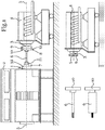
- Fig. 1 a schematic side view of an arrangement according to the invention or a system according to the invention
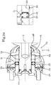
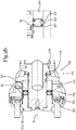
- Fig. 2 a schematic sectional view of a shaft connection device
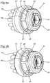
- Fig. 3 different positions of a shaft connection device
- Fig. 4 a schematic oblique view of part of the arrangement and in particular the test specimen coupling device
- Fig. 5 a sectional representation of the schematic view of the test specimen coupling device
- Fig. 6 show the function of the axial connection device.
- the reference symbols correspond to the following components: loading machine connection component 1, loading machine 2, test piece connection component 3, test piece 4, axis of rotation 5, shaft 6, load machine coupling device 7, test piece coupling device 8, test piece adapter 9, shaft adapter 10, form-fit element 11, axial connection device 12, clamping web 13 , Clamping body 14, opening 15, connecting element 16, clamping web release 17, shaft 18, insertion release 19, bayonet ring 20, shaft connection device 21, hub 22, axial locking element 23, axial locking opening 24, actuating device 25, locking lug 26, locking recess 27, stop body 28, actuating element 29, elastic Element 30, control surface 31, elastic coupling 32.
- Fig. 1 shows a schematic side view of an arrangement according to the invention or a system according to the invention which contains an arrangement according to the invention.
- the arrangement comprises a loading machine coupling device 7 for connecting a shaft 6 to the loading machine connection component 1 of a loading machine 2.
- the arrangement comprises a test piece coupling device 8 for connecting the shaft 6 to the test piece connection component 3 of a test piece 4 the arrangement also includes the loading machine 2 and / or the test object 4.
- the arrangement or the system preferably comprises several shafts 6 which can have different physical properties such as different stiffnesses.
- the loading machine coupling device 7 preferably comprises a shaft connection device 21 and possibly an elastic coupling 32.
- the test piece coupling device 8 preferably comprises a shaft adapter 10, a test piece adapter 9 and an axial connection device 12.
- the system or the arrangement can comprise a further test piece 4, which preferably also has a Test specimen adapter 9 is provided so that the test specimens can optionally be connected with their test specimen adapter 9 to the loading machine 2 and in particular to the shaft adapter 10.
- the exchangeable shafts 6 are each provided with a shaft adapter 10.
- the arrangement or the system is preferably designed such that all shaft adapters 10 can be connected to all test specimen adapters 9.
- the shafts preferably have a section for connection to the hub 22 of the shaft connection device 21. These shaft sections of all shafts 6 are preferably designed to be identical or identical in shape, so that the shafts can optionally be connected to the loading machine 2 via the shaft connection device 21 and exchanged.
- the present system or the present arrangement enables the test objects 4 and the shafts 6 to be exchanged quickly and efficiently.
- different test objects 4 and different shafts 6 can be connected one after the other or alternatively with the loading machine 2, whereby the changeover time and the operability are improved.
- Fig. 2 shows two schematic sectional views of a shaft connection device 21 in different positions, wherein Fig. 2a shows the shaft connection device 21 in its open position, in which a shaft 6 can be introduced into the hub 22 in the axial direction, ie along the axis of rotation 5, or can be pulled out of the hub.
- Figure 2b shows the same coupling device as Fig. 2a , but in the closed position in which the axial degree of freedom of the shaft-hub connection is blocked, so that the shaft 6 is axially secured in the shaft connection device 21.
- the shaft connection device 21 is suitable and / or set up for the form-fitting rotary connection of a shaft 6 with a hub 22.
- the shaft-hub connection is preferably designed as a positive-locking rotary connection, in particular as a splined shaft arrangement, as a shaft-hub connection with serration or as a toothed shaft connection.
- This shaft-hub connection preferably includes an axial degree of freedom, so that the shaft 6 or at least a section of the shaft 6 can be inserted into the hub 22 or removed from the hub 22.
- At least one axial securing element 23 is provided, which protrudes into an axial securing opening 24 to block the axial degree of freedom of the shaft-hub connection.
- a plurality of axial securing elements 23 are preferably provided. These can, for example, protrude into an axial securing opening 24 arranged in a ring. If necessary, several axial securing openings 24 are provided, which are designed in such a way that one axial securing element 23 or several axial securing elements 23 can each protrude into one of the axial securing openings 24 in order to block the axial degree of freedom of the shaft-hub connection.
- the axial securing openings 24 are preferably formed in all embodiments by an annular groove and preferably by a single annular groove, which is provided in particular in the area of the shaft section received in the hub 22 is, so that there is no exact rotational alignment of the axial locking openings 24 with respect to the axial locking elements 23.
- the axial securing elements 23 are preferably movable and in particular guided or arranged in a sliding bushing in the hub 22.
- the axial securing elements 23 have an extended position in which they protrude inwardly beyond the hub in order to be introduced into the axial securing openings 24 of the shaft 6, for example.
- the axial securing elements 23 have a retracted position in which they are withdrawn into the hub 22 in such a way that the axial degree of freedom of the shaft-hub connection is released.
- An actuating device 25 is provided for moving or actuating the axial securing elements 23.
- the actuating device 25 comprises an open position in which the axial securing elements 23 are preferably in their retracted position. Furthermore, the actuating device 25 comprises a closed position in which the axial securing elements 23 are preferably in their extended position. It is preferably provided in all embodiments that the actuating device 25 can be latched both in its open position and in its closed position, so that the actuating device 25, in particular, cannot automatically switch from the open position to the closed position or from the closed position to the open position.
- the function of the locking is particularly in the Figures 3a to 3d described.
- the actuating device 25 preferably comprises a stop body 28 and an actuating element 29 which can be moved and locked in relation to the stop body 28.
- the stop body 28 is preferably rigidly connected to the hub 22.
- the shaft connection device 21 preferably comprises an elastic element 30, which is set up to exert a force and, for example, as a compression spring, tension spring or the like Element is formed.
- the elastic element 30 acts on the actuating element 29 and presses the actuating element 29 preferably against the stop body 28. Due to the elastic design of the elastic element 30 and a certain range of motion of the actuating element 29, the actuating element 29 can in the axial direction against the force of the elastic element 30 can be moved. In particular, the actuating element 29 in all embodiments can be moved against the force of the elastic element 30 in such a way that the latching of the actuating device 25 can be released.
- the actuating device 25 comprises at least one control surface 31 for moving the at least one axial securing element 23.
- a control surface 31 is preferably provided, via which a plurality of axial securing elements 23 can be moved.
- the control surface 31 is preferably arranged obliquely along the axial direction of the actuating element 29, whereby in the event of an axial displacement of the actuating element 29, in particular against or with the force of the elastic element 30, the control surface 31 changes the position of the axial securing element 23 or the axial securing elements 23 can.
- the control surface 31 can be designed essentially conical and in particular as an inner conical ring.
- the control surface 31, designed as a conical surface comes into contact with sections of the axial securing elements 23, whereby these are moved from their retracted position to their extended position or from their extended position to their retracted position due to the inclined arrangement of the control surface 31 can.
- the control surface 31, an axial securing element 23 and an axial securing opening 24 are shown enlarged in the open position and the closed position of the actuating device 25.
- a further elastic element 30 is preferably provided, which is suitable and / or designed to move the axial securing element (s) 23.
- the control surface 31 can thus be set up to actively drive a movement of the axial securing elements 23 only in one direction.
- the axial securing elements 23 can be reset, for example, via the elastic element 30, which is designed, for example, as a compression spring.
- the elastic element 30 preferably presses the axial securing element 23 or the axial securing elements 23 against the control surface 31 and thereby elastically counteracts the control or the movement through the control surface 31. As a result, it can be effected, for example, that the axial securing elements 23, driven by the elastic element 30, automatically return to their retracted position when the actuating device 25 is in its open position.
- Figure 2b shows the same device as Fig. 2a , wherein the shaft connection device 21 of Figure 2b is in its closed position.
- the components of the Figure 2b correspond to the components of Fig. 2a .
- the shaft 6 is centered in the hub 22 via a fit, in particular a double fit.
- Both the shaft journal and a shaft shoulder arranged at a distance from the shaft journal are centered in the area of the hub by means of a corresponding fit.
- the Figures 3a to 3d show different positions of a shaft connection device 21, in particular according to FIG Fig. 2a and according to Figure 2b can be designed.
- the shaft connection device 21 comprises a hub 22 for introducing a shaft, not shown.
- the shaft connection device 21 comprises an actuating device 25.
- the actuating device 25 comprises a stop body 28 and an actuating element 29.
- the actuating element 29 is arranged to be movable relative to the stop body 28.
- the actuating device 25 comprises at least one locking lug 26 and at least two latching recesses 27.
- the latching recesses 27 are designed in such a way that the latching lug 26 can optionally be inserted into one of the latching recesses 27.
- the insertion or extraction direction preferably runs approximately axially.
- the locking lug 26 can be removed from one of the locking recesses 27 in the axial direction.
- This movement of the actuating element 29 preferably takes place against the force of an elastic element 30.
- the elastic element 30 is preferably pretensioned in such a way that the actuating element 29 is pressed against the stop body 28.
- the locking lug 26 is pressed into one of the locking recesses 27 by the elastic element 30.
- the actuating device 25 and in particular the actuating element 29 have an intermediate position. In this intermediate position, the locking lug is removed from the locking recess.
- the actuating element 29 in the present embodiment can be rotated relative to the stop body 28.
- the latching recesses 27 are preferably arranged along a pitch circle of the axis of rotation, so that by rotating the actuating element 29 relative to the stop body 28, the choice between the open position and the closed position can be made.
- the latching recesses 27 or the latching lug 26 are preferably designed such that when the latching lug 26 is inserted in a latching recess 27, a rotation or a change between the open position and the closed position is positively prevented.
- the latching recesses 27 are provided in the actuating element 29.
- the locking lug 26 is provided on the stop body 28.
- the locking recesses 27, which are assigned to a locking lug 26, have a different depth in the axial direction, whereby the locking lug 26 can be inserted deeper into one locking recess 27 than into the other Locking recess 27.
- the actuating element 29 thus has a different axial position, depending on which of the two locking recesses 27 the locking lug 26 is inserted into. This difference in the axial position has the effect that the axial securing elements 23, influenced by the control surface 31, are in their extended position when the locking lug 26 is arranged in one of the locking recesses, and that the axial securing elements 23 are in their retracted position when the locking lug 26 is arranged in the other locking recess 27,
- Fig. 3a shows the shaft connection device 21 in which the actuating device 25 is in its open position.
- Figure 3b shows the shaft connection device 21 or its actuating device 25 in an intermediate position in which the locking lug 26 is pulled out of the locking recess 27. This separation takes place by moving the actuating element 29 away from the stop body 28, and in particular against the spring force of the elastic element 30.
- Figure 3c shows the shaft connection device 21 or the actuating device 25 in a further intermediate position in which the locking lug 26 is rotated relative to the second locking recess 27.
- Fig. 3d shows the shaft connection device 21 or its actuating device 25, in which the locking lug 26 is inserted into the other locking recess 27 so that the actuating device 25 is in its closed position.
- the latching lug 26 In order to introduce a latching lug 26 into a latching recess 27, the latching lug 26 must preferably be arranged in alignment with one of the latching recesses 27.
- the position of Fig. 3a corresponds to the position of the Fig. 2a .
- the position of Fig. 3d corresponds to the position of the Figure 2b .
- the latching lug 26 or the latching recesses 27 are designed on the outside and can therefore serve as an indicator for displaying the position of the actuating device 25.
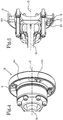
- Fig. 4 shows a schematic oblique view of part of the arrangement and in particular of the test specimen coupling device 8.
- the test specimen coupling device 8 comprises a shaft adapter 10, a test specimen adapter 9 and an axial connection device 12 for axially connecting the shaft adapter 10 to the test specimen adapter 9.
- the axial connection device 12 is preferably not used for transmission of the torque from the test piece connection component 3 of the test piece 4 to the shaft 6, but only for the axial securing and for the connection of the test piece adapter 9 with the shaft adapter 10.
- the torque is transmitted via positive locking elements 11 through which the test piece adapter 9 is positively rotatably connected to the shaft adapter 10 is.
- FIG. 13 shows a sectional illustration of the schematic view of the test specimen coupling device 8 or parts of the arrangement of FIG Fig. 4 .
- the shaft 6 has a flexible shaft connection and, in particular, a constant velocity joint at its end arranged in the test specimen coupling device 8.
- the test piece adapter 9 is set up to be connected to the test piece connection component 3 of the test piece 4. This connection takes place in the present case and preferably in all embodiments via a screw or flange connection.
- the shaft adapter 10 is connected to the constant velocity joint of the shaft 6.
- any connection can be used which enables the shaft adapter 10 to be connected to the shaft 6 in the present arrangement.
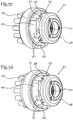
- the Figures 6a , 6b and 6c show the function of the axial connection device 12 for the axial connection of the test specimen adapter 9 to the shaft adapter 10.
- Both the test specimen adapter 9 and the shaft adapter 10 include form-fit elements 11. These form-fit elements 11 are in particular on the mutually facing Sides of the shaft adapter 10 and the test specimen adapter 9 are provided.
- the form-fit elements 11 are set up in particular to produce a form-fit rotary connection between the shaft adapter 10 and the test piece adapter 9.
- the form-locking elements 11 of the two adapters 9, 10 are designed to be plugged into one another in the axial direction, that is to say along the axis of rotation 5.
- the form-fit elements 11 are set up for the transmission and in particular for the form-fit rotary transmission of the torque.
- the axial connection device 12 is provided for the axial connection and thus for the axial securing of this rotary connection.
- the test specimen adapter 9 and the shaft adapter 10 form a clamping web 13 when the positive rotary connection is established.
- This clamping web 13 is clamped between two clamping bodies 14 in order to establish an axial connection between the test specimen adapter 9 and the shaft adapter 10.
- a section of the shaft adapter 10 and of the test specimen adapter 9 can run parallel along the course of the clamping web 13 and essentially transversely or normal to the clamping force of the clamping bodies 14.
- the test specimen adapter 9 and the shaft adapter 10 preferably comprise openings 15 running in the axial direction, which are in particular designed as through openings.
- the axial connection device 12 comprises connection elements 16 which can be passed through the openings 15.
- the connecting elements 16 preferably include a shaft 18 which protrudes through the opening 15 in order to connect the two clamping bodies 14 to one another in such a way that they cause the clamping web to jam.
- the openings 15 each preferably include a clamping web exposure 17 and an insertion exposure 19. Due to the special design of the openings 15 and the axial connection device 12, they are bayonet-like actuatable axial connection device 12 is formed.
- the connecting elements 16 can be introduced essentially in the axial direction through the openings 15 and, in particular, through the insertion clearance 19 of the opening 15. In this position, the connecting element 16 can then be moved into the clamping web release position 17 by means of a rotary movement.
- the shaft 18 of the connecting element 16 is designed in such a way that it fits into the clamping web clearance 17.
- Figure 6b shows a position in which the connecting elements 16 are inserted into the insertion free position 19.
- Figure 6c shows a position in which the connecting elements 16 are inserted into the clamping web clearances 17 via a rotary movement.
- the connecting elements 16 comprise two clamping bodies 14, one clamping body 14 being configured as a screw head or as a screw nut and the other clamping element 14 as a tab or web.
- a plurality of connecting elements 16 are preferably connected to one another via a bayonet ring 20.
- the connecting elements 16 are arranged along the course of the bayonet ring 20 in such a way that they can be inserted into the openings 15 of the adapters 9, 10.
- Those designed as webs or tabs are preferred Clamping body 14 connected to the bayonet ring, and optionally connected in one piece.
- the clamping bodies, which are designed as webs or tabs, preferably protrude inward from the bayonet ring 20.
- the clamping web 13 as in particular in the Figures 6 is shown, formed substantially C-shaped, the legs of the clamping web 13 extending substantially along a pitch circle around the axis of rotation 5.
- the C-shaped clamping web 13 has an opening 15 which is formed in particular by the clamping web release 17.
- the clamping web release 17 is essentially in the form of a slot and / or following a pitch circle around the axis of rotation 5.
- the clamping web release 17 opens into the insertion release 19 of the opening 15, as a result of which a connecting element 16 inserted through the insertion release 19 can subsequently be inserted into the clamping web release 17.
- the form-locking elements 11, or their form-locking flanks can be provided between the openings 15. If necessary, only one opening 15 and one connecting element 16 are provided. If necessary, two, three, four, five or more connecting elements 16 with correspondingly arranged openings 15 are provided.
- the arrangement comprises a test piece coupling device 8, which according to one of the Figures 4, 5 or 6th is trained.
- This arrangement preferably comprises a loading machine coupling device which, according to one of the Figures 2 or 3 is trained.
Landscapes
- Engineering & Computer Science (AREA)
- General Engineering & Computer Science (AREA)
- Mechanical Engineering (AREA)
- Physics & Mathematics (AREA)
- General Physics & Mathematics (AREA)
- Investigating Strength Of Materials By Application Of Mechanical Stress (AREA)
- Mutual Connection Of Rods And Tubes (AREA)
- Testing Of Engines (AREA)
Claims (14)
- Agencement pour le raccordement rotatif d'un élément de connexion d'un dynamomètre (2) d'un banc d'essai avec l'élément connexion d'objet d'essai (3) d'un objet d'essai (4), comprenant:- au moins un arbre (6) s'étendant le long de l'axe de rotation (5) du raccordement rotatif,- un dispositif d'accouplement de dynamomètre (7) pour le raccordement rotatif de l'arbre (6) avec l'élément de connexion de dynamomètre (1),- un dispositif d'accouplement de dynamomètre (7) pour le raccordement rotatif de l'arbre (6) avec l'élément de connexion de dynamomètre (1),- un dispositif d'accouplement d'objet d'essai (8) pour le raccordement rotatif de l'arbre (6) avec l'élément de connexion d'objet d'essai (3),caractérisé en ce- que le dispositif d'accouplement d'objet d'essai (8) comprend au moins un adaptateur d'objet d'essai (9) qui peut être relié ou est relié à l'élément de connexion d'objet d'essai (3) d'une objet d'essai (4) et un adaptateur d'arbre (10) qui peut être relié ou est relié à l'arbre (6),- que l'adaptateur d'objet d'essai (9) et l'adaptateur d'arbre (10) comprennent des éléments d'engagement positif (11) pour le raccordement rotatif amovible et positif de l'adaptateur d'objet d'essai (9) avec l'adaptateur d'arbre (10),- qu'un dispositif de liaison axiale (12) est prévu pour la liaison axiale de l'adaptateur d'objet d'essai (9) à l'adaptateur d'arbre (10),- que le dispositif de liaison axiale (12) est conçu comme une fermeture à baïonnette,- qu'une barre de serrage (13) peut être disposée entre les corps de serrage (14) du dispositif de liaison axiale (12) par une séquence de mouvements d'un mouvement axial et d'un mouvement de rotation du dispositif de liaison axiale (12),- et que les corps de serrage (14) agissent comme un moyen de blocage axiale contre une séparation axiale de l'adaptateur d'objet d'essai (9) de l'adaptateur d'arbre (10) et comme un dispositif anti-torsion pour le dispositif de liaison axiale (12) conçu comme une fermeture à baïonnette.
- Agencement selon la revendication 1, caractérisé en ce que les éléments d'engagement positif (11) font saillie depuis les côtés se faisant face de l'adaptateur d'arbre (10) et de l'adaptateur d'objet d'essai (9) essentiellement le long de la direction de l'axe de rotation (5), c'est-à-dire axialement, et peuvent être emboîtés l'un dans l'autre dans le sens axial pour réaliser le raccordement rotatif positif et peuvent être séparés les uns des autres dans le sens axial afin de séparer le raccordement rotatif positif.
- Agencement selon la revendication 1 ou 2, caractérisé en ce que lorsque la liaison rotative positive est établie, l'adaptateur d'objet d'essai (9) et l'adaptateur d'arbre (10) forment ensemble une barre de serrage (13) qui est serrée entre les corps de serrage (14) du dispositif de liaison axiale (12) pour le raccordement axial de l'adaptateur d'objet d'essai (9) à l'adaptateur d'arbre (10).
- Agencement selon l'une des revendications 1 à 3, caractérisé en ce- que l'adaptateur d'objet d'essai (9) et l'adaptateur d'arbre (10) présentent des ouvertures (15) s'étendant dans la direction axiale,- que la au moins une ouverture (15) de l'adaptateur d'objet d'essai (9) est agencée de sorte qu'elle soit au moins partiellement alignée avec la au moins une ouverture (15) de l'adaptateur d'arbre (10) lorsque les éléments d'engagement positif (11) de l'adaptateur d'objet d'essai (9) avec les éléments d'engagement positif (11) de l'adaptateur d'arbre (10) sont en prise pour le raccordement rotatif,- et en ce que le dispositif de liaison axiale (12) comprend au moins un élément de liaison (16) qui fait saillie à travers les ouvertures (15) pour la liaison axiale de l'adaptateur d'objet d'essai (9) à l'adaptateur d'arbre (10).
- Agencement selon l'une des revendications 1 à 4, caractérisé en ce- que l'adaptateur d'objet d'essai (9) et l'adaptateur d'arbre (10) présentent des ouvertures (15) s'étendant dans le sens axial,- que les ouvertures (15) de l'adaptateur d'objet d'essai (9) sont disposées de sorte qu'elles soient au moins partiellement alignées avec les ouvertures (15) de l'adaptateur d'arbre (10) lorsque les éléments d'engagement positif (11) de l'adaptateur d'objet d'essai (9) avec les éléments d'engagement positif (11) de l'adaptateur d'arbre (10) sont en prise pour le raccordement rotatif,- que le dispositif de liaison axiale (12) des éléments de liaison (16) qui font saillie à travers les ouvertures (15) pour la liaison axiale de l'adaptateur d'objet d'essai (9) avec l'adaptateur d'arbre (10),- que les ouvertures (15) comportent chacune un jeu d'insertion (19) pour l'introduction axiale de l'élément de liaison (16) du dispositif de liaison axiale (12) et un jeu de barre de serrage (17) pour le raccordement axial de l'adaptateur d'objet d'essai (9) à l'adaptateur d'arbre (10) par actionnement de l'élément de liaison (16), dans lequel le jeu de la barre de serrage (17) s'étend le long d'un cercle primitif autour de l'axe de rotation (5) et est en particulier courbé en forme de trou allongé,- que les éléments de liaison (16) comprennent chacun une tige (18) avec une épaisseur de tige et deux corps de serrage supérieures à l'épaisseur de la tige (14),- que transversalement à sa course et en particulier dans le sens radial, le jeu de barre de serrage (17) présente une largeur libre qui est supérieure à l'épaisseur de la tige de ladite tige (18) de l'élément de liaison (16) respectif mais est dépassée par les deux corps de serrage (14) de l'élément de liaison (16),- que le jeu d'insertion (19) est supérieur à la section relative d'au moins l'un des deux corps de serrage (14) ou des deux corps de serrage (14) de l'élément de liaison (16),- de sorte que les éléments de liaison (16) du dispositif de liaison axiale (12) puissent être insérés dans la direction axiale dans les jeux d'insertion (19) des ouvertures (15) à la manière d'une fermeture à baïonnette, puissent être tournés le long de l'extension des jeux de barre de serrage (17) des ouvertures (15) autour de l'axe de rotation (5), et puissent être fixées par serrage de la barre de serrage (13) entre les corps de serrage (14).
- Agencement selon l'une des revendications 4 ou 5, caractérisé en ce que les éléments de liaison (16) comprennent chacun une liaison vissée, la tige (18) de l'élément de liaison (16) étant une tige filetée qui est vissée ou peut être vissée dans au moins l'un des deux corps de serrage (14), et que la distance et la force de serrage entre les deux corps de serrage (14) peuvent être modifiés en modifiant la profondeur de vissage.
- Agencement selon l'une des revendications 1 à 6, caractérisé en ce que le dispositif de liaison axiale (12) comprend un anneau à baïonnette (20), par l'intermédiaire duquel les éléments de liaison (16) du dispositif de liaison axiale (12) sont reliés les uns aux autres.
- Agencement selon l'une des revendications 1 à 7, caractérisé en ce que les éléments d'engagement positif (11) de l'adaptateur d'objet d'essai (9) présentent essentiellement une forme négative fonctionnelle des éléments d'engagement positif (11) de l'adaptateur d'arbre (10),
les éléments d'engagement positif (11) de l'adaptateur d'objet d'essai (9) et les éléments d'engagement positif (11) de l'adaptateur d'arbre (10) formant ensemble un raccordement rotatif positif essentiellement sans jeu ou formant un raccordement rotatif positif qui est sensiblement sans jeu dans les deux sens de rotation. - Agencement selon l'une des revendications 1 à 8, caractérisé en ce que le dispositif d'accouplement d'objet d'essai (8) comprend une liaison d'arbre flexible, un joint universel ou un joint homocinétique pour le raccordement à l'arbre (6).
- Système comprenant un agencement selon l'une des revendications 1 à 9, caractérisé en ce que plusieurs arbres (6) avec des raideurs différentes sont prévus ou disponibles, qui peuvent être utilisés pour modifier la rigidité de la colonne de mesure de l'agencement pour relier au choix le dispositif d'accouplement du dynamomètre (7) au dispositif d'accouplement d'objet d'essai (8).
- Système comprenant un agencement selon l'une des revendications 1 à 9, caractérisé en ce que plusieurs arbres (6) avec des raideurs différentes sont prévus ou disponibles, qui peuvent être utilisés pour modifier la rigidité de la colonne de mesure de l'agencement pour relier au choix le dispositif d'accouplement du dynamomètre (7) au dispositif d'accouplement de l'objet d'essai (8), et que les arbres (6) sont reliés chacun à un adaptateur d'arbre (10).
- Système comprenant un agencement selon l'une des revendications 1 à 9, caractérisé en ce que plusieurs objets d'essai (4) sont fournis, chacun d'eux étant connecté à un adaptateur d'objets d'essai (9), les objets d'essai (4) et leurs adaptateurs d'objet d'essai (9) pouvant être au choix connectés au dynamomètre (2) par connexion avec l'adaptateur d'arbre (10).
- Système comprenant un agencement selon l'une des revendications 1 à 9, caractérisé en ce que les éléments d'engagement positif (11) de tous les adaptateurs d'arbre (10) sont adaptés et configurés pour le raccordement rotatif positif avec les éléments d'engagement positif (11) de tous les adaptateurs d'objet d'essai (9).
- Système comprenant un agencement selon l'une des revendications 1 à 9, caractérisé en ce que le système comprend un dynamomètre d'un banc d'essai (2) et en particulier un banc d'essai de moteur.
Applications Claiming Priority (2)
| Application Number | Priority Date | Filing Date | Title |
|---|---|---|---|
| ATA495/2015A AT517763B1 (de) | 2015-07-23 | 2015-07-23 | Anordnung zur Drehverbindung einer Belastungsmaschine eines Prüfstandes mit einem Prüfling |
| PCT/EP2016/067238 WO2017013147A1 (fr) | 2015-07-23 | 2016-07-20 | Système pour relier à rotation une machine de charge d'un banc de test à un échantillon |
Publications (2)
| Publication Number | Publication Date |
|---|---|
| EP3325834A1 EP3325834A1 (fr) | 2018-05-30 |
| EP3325834B1 true EP3325834B1 (fr) | 2020-11-18 |
Family
ID=56464208
Family Applications (1)
| Application Number | Title | Priority Date | Filing Date |
|---|---|---|---|
| EP16741017.4A Active EP3325834B1 (fr) | 2015-07-23 | 2016-07-20 | Système pour relier à rotation une machine de charge d'un banc de test à un échantillon |
Country Status (3)
| Country | Link |
|---|---|
| EP (1) | EP3325834B1 (fr) |
| AT (2) | AT517763B1 (fr) |
| WO (1) | WO2017013147A1 (fr) |
Families Citing this family (4)
| Publication number | Priority date | Publication date | Assignee | Title |
|---|---|---|---|---|
| DE102019205567A1 (de) * | 2019-04-17 | 2020-10-22 | Robert Bosch Gmbh | Steckverzahnung mit kreis- oder ringförmigen Federelementen |
| AT523301B1 (de) | 2019-12-20 | 2022-07-15 | Seibt Kristl & Co Gmbh | Verbindungsvorrichtung für Wellen und Wellenanordnung mit einer Verbindungsvorrichtung |
| CN114673734B (zh) * | 2022-05-27 | 2022-08-05 | 中国飞机强度研究所 | 一种飞机强度测试试验用振动锁紧系统及其方法 |
| DE102023205449A1 (de) * | 2023-06-13 | 2024-12-19 | Zf Friedrichshafen Ag | Kupplungsmodul für einen Antriebsstrangprüfstand, Baukastensystem und Antriebsstrangprüfstand |
Family Cites Families (8)
| Publication number | Priority date | Publication date | Assignee | Title |
|---|---|---|---|---|
| DE440816C (de) * | 1924-12-23 | 1927-02-16 | Albert Hirth Dr Ing | Wellenkupplung |
| DE814352C (de) * | 1948-10-02 | 1951-09-20 | Moeckmuehl G M B H Maschf | Schnellverschluss fuer auswechselbare Raeder, Umlaufwerkzeuge o. dgl. |
| GB929323A (en) * | 1961-05-17 | 1963-06-19 | Ass Elect Ind | Improved flexible coupling particularly for turbine-generator equipment |
| DE2715639C2 (de) * | 1977-04-07 | 1979-06-07 | Gelenkwellenbau Gmbh, 4300 Essen | Gelenkwelle |
| DE3561489D1 (en) * | 1985-03-01 | 1988-02-25 | Schenck Ag Carl | Process and device for operating a test stand for power engines, and a rotary-absorption dynamometer therefor |
| DE10025095A1 (de) * | 2000-05-20 | 2001-11-22 | Volkswagen Ag | Prüfstand für Brennkraftmaschinen |
| DE20205371U1 (de) * | 2002-04-07 | 2002-09-12 | Brehm, Bernhardt, 75365 Calw | Kupplung für elektrische Antriebseinheit |
| CN203348358U (zh) * | 2013-06-19 | 2013-12-18 | 江苏荣基重工科技有限公司 | 一种万向轴 |
-
2015
- 2015-07-23 AT ATA495/2015A patent/AT517763B1/de active
-
2016
- 2016-07-12 AT ATGM50139/2016U patent/AT15100U1/de not_active IP Right Cessation
- 2016-07-20 EP EP16741017.4A patent/EP3325834B1/fr active Active
- 2016-07-20 WO PCT/EP2016/067238 patent/WO2017013147A1/fr not_active Ceased
Non-Patent Citations (1)
| Title |
|---|
| None * |
Also Published As
| Publication number | Publication date |
|---|---|
| AT517763A1 (de) | 2017-04-15 |
| EP3325834A1 (fr) | 2018-05-30 |
| AT517763B1 (de) | 2018-01-15 |
| AT15100U1 (de) | 2016-12-15 |
| WO2017013147A1 (fr) | 2017-01-26 |
Similar Documents
| Publication | Publication Date | Title |
|---|---|---|
| DE102011109705A1 (de) | Lenkungsanordnung | |
| DE102011109691A1 (de) | Lenkspindelanordnung | |
| EP3325834B1 (fr) | Système pour relier à rotation une machine de charge d'un banc de test à un échantillon | |
| DE2445041A1 (de) | Wellenkupplung insbesondere fuer gasturbinenstrahltriebwerke | |
| EP3327187A1 (fr) | Cloche de rotor et rotor pour métier à filer à bout libre doté d'une cloche de rotor | |
| DE1253524B (de) | Kardangelenkkupplung | |
| DE1750948B1 (de) | Einrichtung an gelenkwellen mit kreuzgelenken insbesondere fuer landmanschinen zum verhindern des gelenkebenenversatzes | |
| DE102014207132A1 (de) | Abzweig-/Differenzialgetriebe | |
| DE102007038878A1 (de) | Verbindungsanordnung zwischen einem Wellenzapfen und einem Gelenkteil | |
| EP3325835B1 (fr) | Dispositif de raccordement d'arbre et système pour raccorder à rotation une machine de charge d'un banc de test à un échantillon | |
| DE102011050748B3 (de) | Verbindung eines Wellenstücks einer Lenkwelle für ein Kraftfahrzeug mit einem Anschlussteil | |
| DE102014207134A1 (de) | Differenzialgetriebe mit Beschränkungsmechanismus | |
| DE3730728C2 (fr) | ||
| DE102018214082A1 (de) | Klaue mit Geberkontur und Kupplungsanordnung | |
| DE102013206061A1 (de) | Betätigungsvorrichtung einer aerodynamisch wirksamen Fläche | |
| EP2776730A1 (fr) | Groupe moteur | |
| DE102022103040A1 (de) | Spindelantrieb-Baukastensystem sowie Spindelantrieb | |
| DE102013018649B4 (de) | Formschlüssige Kupplung | |
| EP4506582B1 (fr) | Arbre de fourche | |
| WO2013020546A1 (fr) | Amortisseur de vibrations pour une chaîne cinématique | |
| DE102017105558A1 (de) | Maschinenteil, verbund und verwendung eines maschinenteils zum bilden eines verbundes | |
| DE102017221704A1 (de) | Kupplungssystem zum axialen Verbinden zweier Bauteile, insbesondere zur Anbindung eines Prüflings oder einer Adaption auf einem Prüfstand | |
| WO2012171613A1 (fr) | Ensemble de liaison entre un arbre articulé et une transmission | |
| DE102006048855A1 (de) | Verbindungsanordnung | |
| DE102014223082A1 (de) | Getriebegehäuse mit abnehmbarem Nebengehäuseteil zur erleichterten Gummilagermontage |
Legal Events
| Date | Code | Title | Description |
|---|---|---|---|
| STAA | Information on the status of an ep patent application or granted ep patent |
Free format text: STATUS: THE INTERNATIONAL PUBLICATION HAS BEEN MADE |
|
| PUAI | Public reference made under article 153(3) epc to a published international application that has entered the european phase |
Free format text: ORIGINAL CODE: 0009012 |
|
| STAA | Information on the status of an ep patent application or granted ep patent |
Free format text: STATUS: REQUEST FOR EXAMINATION WAS MADE |
|
| 17P | Request for examination filed |
Effective date: 20180221 |
|
| AK | Designated contracting states |
Kind code of ref document: A1 Designated state(s): AL AT BE BG CH CY CZ DE DK EE ES FI FR GB GR HR HU IE IS IT LI LT LU LV MC MK MT NL NO PL PT RO RS SE SI SK SM TR |
|
| AX | Request for extension of the european patent |
Extension state: BA ME |
|
| DAV | Request for validation of the european patent (deleted) | ||
| DAX | Request for extension of the european patent (deleted) | ||
| GRAP | Despatch of communication of intention to grant a patent |
Free format text: ORIGINAL CODE: EPIDOSNIGR1 |
|
| STAA | Information on the status of an ep patent application or granted ep patent |
Free format text: STATUS: GRANT OF PATENT IS INTENDED |
|
| INTG | Intention to grant announced |
Effective date: 20200625 |
|
| GRAS | Grant fee paid |
Free format text: ORIGINAL CODE: EPIDOSNIGR3 |
|
| GRAA | (expected) grant |
Free format text: ORIGINAL CODE: 0009210 |
|
| STAA | Information on the status of an ep patent application or granted ep patent |
Free format text: STATUS: THE PATENT HAS BEEN GRANTED |
|
| AK | Designated contracting states |
Kind code of ref document: B1 Designated state(s): AL AT BE BG CH CY CZ DE DK EE ES FI FR GB GR HR HU IE IS IT LI LT LU LV MC MK MT NL NO PL PT RO RS SE SI SK SM TR |
|
| REG | Reference to a national code |
Ref country code: GB Ref legal event code: FG4D Free format text: NOT ENGLISH |
|
| REG | Reference to a national code |
Ref country code: CH Ref legal event code: EP |
|
| REG | Reference to a national code |
Ref country code: DE Ref legal event code: R096 Ref document number: 502016011745 Country of ref document: DE |
|
| REG | Reference to a national code |
Ref country code: IE Ref legal event code: FG4D Free format text: LANGUAGE OF EP DOCUMENT: GERMAN |
|
| REG | Reference to a national code |
Ref country code: AT Ref legal event code: REF Ref document number: 1336100 Country of ref document: AT Kind code of ref document: T Effective date: 20201215 |
|
| REG | Reference to a national code |
Ref country code: NL Ref legal event code: MP Effective date: 20201118 |
|
| PG25 | Lapsed in a contracting state [announced via postgrant information from national office to epo] |
Ref country code: PT Free format text: LAPSE BECAUSE OF FAILURE TO SUBMIT A TRANSLATION OF THE DESCRIPTION OR TO PAY THE FEE WITHIN THE PRESCRIBED TIME-LIMIT Effective date: 20210318 Ref country code: RS Free format text: LAPSE BECAUSE OF FAILURE TO SUBMIT A TRANSLATION OF THE DESCRIPTION OR TO PAY THE FEE WITHIN THE PRESCRIBED TIME-LIMIT Effective date: 20201118 Ref country code: NO Free format text: LAPSE BECAUSE OF FAILURE TO SUBMIT A TRANSLATION OF THE DESCRIPTION OR TO PAY THE FEE WITHIN THE PRESCRIBED TIME-LIMIT Effective date: 20210218 Ref country code: FI Free format text: LAPSE BECAUSE OF FAILURE TO SUBMIT A TRANSLATION OF THE DESCRIPTION OR TO PAY THE FEE WITHIN THE PRESCRIBED TIME-LIMIT Effective date: 20201118 Ref country code: GR Free format text: LAPSE BECAUSE OF FAILURE TO SUBMIT A TRANSLATION OF THE DESCRIPTION OR TO PAY THE FEE WITHIN THE PRESCRIBED TIME-LIMIT Effective date: 20210219 |
|
| PG25 | Lapsed in a contracting state [announced via postgrant information from national office to epo] |
Ref country code: LV Free format text: LAPSE BECAUSE OF FAILURE TO SUBMIT A TRANSLATION OF THE DESCRIPTION OR TO PAY THE FEE WITHIN THE PRESCRIBED TIME-LIMIT Effective date: 20201118 Ref country code: PL Free format text: LAPSE BECAUSE OF FAILURE TO SUBMIT A TRANSLATION OF THE DESCRIPTION OR TO PAY THE FEE WITHIN THE PRESCRIBED TIME-LIMIT Effective date: 20201118 Ref country code: IS Free format text: LAPSE BECAUSE OF FAILURE TO SUBMIT A TRANSLATION OF THE DESCRIPTION OR TO PAY THE FEE WITHIN THE PRESCRIBED TIME-LIMIT Effective date: 20210318 Ref country code: BG Free format text: LAPSE BECAUSE OF FAILURE TO SUBMIT A TRANSLATION OF THE DESCRIPTION OR TO PAY THE FEE WITHIN THE PRESCRIBED TIME-LIMIT Effective date: 20210218 Ref country code: SE Free format text: LAPSE BECAUSE OF FAILURE TO SUBMIT A TRANSLATION OF THE DESCRIPTION OR TO PAY THE FEE WITHIN THE PRESCRIBED TIME-LIMIT Effective date: 20201118 |
|
| REG | Reference to a national code |
Ref country code: LT Ref legal event code: MG9D |
|
| PG25 | Lapsed in a contracting state [announced via postgrant information from national office to epo] |
Ref country code: HR Free format text: LAPSE BECAUSE OF FAILURE TO SUBMIT A TRANSLATION OF THE DESCRIPTION OR TO PAY THE FEE WITHIN THE PRESCRIBED TIME-LIMIT Effective date: 20201118 |
|
| PG25 | Lapsed in a contracting state [announced via postgrant information from national office to epo] |
Ref country code: LT Free format text: LAPSE BECAUSE OF FAILURE TO SUBMIT A TRANSLATION OF THE DESCRIPTION OR TO PAY THE FEE WITHIN THE PRESCRIBED TIME-LIMIT Effective date: 20201118 Ref country code: SM Free format text: LAPSE BECAUSE OF FAILURE TO SUBMIT A TRANSLATION OF THE DESCRIPTION OR TO PAY THE FEE WITHIN THE PRESCRIBED TIME-LIMIT Effective date: 20201118 Ref country code: EE Free format text: LAPSE BECAUSE OF FAILURE TO SUBMIT A TRANSLATION OF THE DESCRIPTION OR TO PAY THE FEE WITHIN THE PRESCRIBED TIME-LIMIT Effective date: 20201118 Ref country code: CZ Free format text: LAPSE BECAUSE OF FAILURE TO SUBMIT A TRANSLATION OF THE DESCRIPTION OR TO PAY THE FEE WITHIN THE PRESCRIBED TIME-LIMIT Effective date: 20201118 Ref country code: SK Free format text: LAPSE BECAUSE OF FAILURE TO SUBMIT A TRANSLATION OF THE DESCRIPTION OR TO PAY THE FEE WITHIN THE PRESCRIBED TIME-LIMIT Effective date: 20201118 Ref country code: RO Free format text: LAPSE BECAUSE OF FAILURE TO SUBMIT A TRANSLATION OF THE DESCRIPTION OR TO PAY THE FEE WITHIN THE PRESCRIBED TIME-LIMIT Effective date: 20201118 |
|
| REG | Reference to a national code |
Ref country code: DE Ref legal event code: R097 Ref document number: 502016011745 Country of ref document: DE |
|
| PG25 | Lapsed in a contracting state [announced via postgrant information from national office to epo] |
Ref country code: DK Free format text: LAPSE BECAUSE OF FAILURE TO SUBMIT A TRANSLATION OF THE DESCRIPTION OR TO PAY THE FEE WITHIN THE PRESCRIBED TIME-LIMIT Effective date: 20201118 |
|
| PLBE | No opposition filed within time limit |
Free format text: ORIGINAL CODE: 0009261 |
|
| STAA | Information on the status of an ep patent application or granted ep patent |
Free format text: STATUS: NO OPPOSITION FILED WITHIN TIME LIMIT |
|
| 26N | No opposition filed |
Effective date: 20210819 |
|
| PG25 | Lapsed in a contracting state [announced via postgrant information from national office to epo] |
Ref country code: NL Free format text: LAPSE BECAUSE OF FAILURE TO SUBMIT A TRANSLATION OF THE DESCRIPTION OR TO PAY THE FEE WITHIN THE PRESCRIBED TIME-LIMIT Effective date: 20201118 Ref country code: AL Free format text: LAPSE BECAUSE OF FAILURE TO SUBMIT A TRANSLATION OF THE DESCRIPTION OR TO PAY THE FEE WITHIN THE PRESCRIBED TIME-LIMIT Effective date: 20201118 Ref country code: IT Free format text: LAPSE BECAUSE OF FAILURE TO SUBMIT A TRANSLATION OF THE DESCRIPTION OR TO PAY THE FEE WITHIN THE PRESCRIBED TIME-LIMIT Effective date: 20201118 |
|
| PG25 | Lapsed in a contracting state [announced via postgrant information from national office to epo] |
Ref country code: SI Free format text: LAPSE BECAUSE OF FAILURE TO SUBMIT A TRANSLATION OF THE DESCRIPTION OR TO PAY THE FEE WITHIN THE PRESCRIBED TIME-LIMIT Effective date: 20201118 |
|
| PG25 | Lapsed in a contracting state [announced via postgrant information from national office to epo] |
Ref country code: ES Free format text: LAPSE BECAUSE OF FAILURE TO SUBMIT A TRANSLATION OF THE DESCRIPTION OR TO PAY THE FEE WITHIN THE PRESCRIBED TIME-LIMIT Effective date: 20201118 |
|
| REG | Reference to a national code |
Ref country code: CH Ref legal event code: PL |
|
| GBPC | Gb: european patent ceased through non-payment of renewal fee |
Effective date: 20210720 |
|
| PG25 | Lapsed in a contracting state [announced via postgrant information from national office to epo] |
Ref country code: MC Free format text: LAPSE BECAUSE OF FAILURE TO SUBMIT A TRANSLATION OF THE DESCRIPTION OR TO PAY THE FEE WITHIN THE PRESCRIBED TIME-LIMIT Effective date: 20201118 |
|
| REG | Reference to a national code |
Ref country code: BE Ref legal event code: MM Effective date: 20210731 |
|
| PG25 | Lapsed in a contracting state [announced via postgrant information from national office to epo] |
Ref country code: LI Free format text: LAPSE BECAUSE OF NON-PAYMENT OF DUE FEES Effective date: 20210731 Ref country code: GB Free format text: LAPSE BECAUSE OF NON-PAYMENT OF DUE FEES Effective date: 20210720 Ref country code: CH Free format text: LAPSE BECAUSE OF NON-PAYMENT OF DUE FEES Effective date: 20210731 |
|
| PG25 | Lapsed in a contracting state [announced via postgrant information from national office to epo] |
Ref country code: IS Free format text: LAPSE BECAUSE OF FAILURE TO SUBMIT A TRANSLATION OF THE DESCRIPTION OR TO PAY THE FEE WITHIN THE PRESCRIBED TIME-LIMIT Effective date: 20210318 Ref country code: LU Free format text: LAPSE BECAUSE OF NON-PAYMENT OF DUE FEES Effective date: 20210720 Ref country code: FR Free format text: LAPSE BECAUSE OF NON-PAYMENT OF DUE FEES Effective date: 20210731 |
|
| PG25 | Lapsed in a contracting state [announced via postgrant information from national office to epo] |
Ref country code: IE Free format text: LAPSE BECAUSE OF NON-PAYMENT OF DUE FEES Effective date: 20210720 Ref country code: BE Free format text: LAPSE BECAUSE OF NON-PAYMENT OF DUE FEES Effective date: 20210731 |
|
| REG | Reference to a national code |
Ref country code: AT Ref legal event code: MM01 Ref document number: 1336100 Country of ref document: AT Kind code of ref document: T Effective date: 20210720 |
|
| PG25 | Lapsed in a contracting state [announced via postgrant information from national office to epo] |
Ref country code: AT Free format text: LAPSE BECAUSE OF NON-PAYMENT OF DUE FEES Effective date: 20210720 |
|
| PG25 | Lapsed in a contracting state [announced via postgrant information from national office to epo] |
Ref country code: HU Free format text: LAPSE BECAUSE OF FAILURE TO SUBMIT A TRANSLATION OF THE DESCRIPTION OR TO PAY THE FEE WITHIN THE PRESCRIBED TIME-LIMIT; INVALID AB INITIO Effective date: 20160720 |
|
| P01 | Opt-out of the competence of the unified patent court (upc) registered |
Effective date: 20230502 |
|
| PG25 | Lapsed in a contracting state [announced via postgrant information from national office to epo] |
Ref country code: CY Free format text: LAPSE BECAUSE OF FAILURE TO SUBMIT A TRANSLATION OF THE DESCRIPTION OR TO PAY THE FEE WITHIN THE PRESCRIBED TIME-LIMIT Effective date: 20201118 |
|
| REG | Reference to a national code |
Ref country code: DE Ref legal event code: R082 Ref document number: 502016011745 Country of ref document: DE Representative=s name: STOLMAR & PARTNER PATENTANWAELTE PARTG MBB, DE Ref country code: DE Ref legal event code: R082 Ref document number: 502016011745 Country of ref document: DE Representative=s name: STOLMAR & PARTNER INTELLECTUAL PROPERTY GMBH, CH |
|
| PG25 | Lapsed in a contracting state [announced via postgrant information from national office to epo] |
Ref country code: MK Free format text: LAPSE BECAUSE OF FAILURE TO SUBMIT A TRANSLATION OF THE DESCRIPTION OR TO PAY THE FEE WITHIN THE PRESCRIBED TIME-LIMIT Effective date: 20201118 |
|
| PG25 | Lapsed in a contracting state [announced via postgrant information from national office to epo] |
Ref country code: TR Free format text: LAPSE BECAUSE OF FAILURE TO SUBMIT A TRANSLATION OF THE DESCRIPTION OR TO PAY THE FEE WITHIN THE PRESCRIBED TIME-LIMIT Effective date: 20201118 |
|
| PG25 | Lapsed in a contracting state [announced via postgrant information from national office to epo] |
Ref country code: MT Free format text: LAPSE BECAUSE OF FAILURE TO SUBMIT A TRANSLATION OF THE DESCRIPTION OR TO PAY THE FEE WITHIN THE PRESCRIBED TIME-LIMIT Effective date: 20201118 |
|
| REG | Reference to a national code |
Ref country code: DE Ref legal event code: R082 Ref document number: 502016011745 Country of ref document: DE Representative=s name: STOLMAR & PARTNER INTELLECTUAL PROPERTY GMBH, CH |
|
| PGFP | Annual fee paid to national office [announced via postgrant information from national office to epo] |
Ref country code: DE Payment date: 20250709 Year of fee payment: 10 |