EP3325848B1 - Liaison soudee entre une couronne de differentiel et son boitier - Google Patents
Liaison soudee entre une couronne de differentiel et son boitier Download PDFInfo
- Publication number
- EP3325848B1 EP3325848B1 EP16742333.4A EP16742333A EP3325848B1 EP 3325848 B1 EP3325848 B1 EP 3325848B1 EP 16742333 A EP16742333 A EP 16742333A EP 3325848 B1 EP3325848 B1 EP 3325848B1
- Authority
- EP
- European Patent Office
- Prior art keywords
- casing
- crown
- ring gear
- differential
- cutout
- Prior art date
- Legal status (The legal status is an assumption and is not a legal conclusion. Google has not performed a legal analysis and makes no representation as to the accuracy of the status listed.)
- Active
Links
Images

Classifications
-
- F—MECHANICAL ENGINEERING; LIGHTING; HEATING; WEAPONS; BLASTING
- F16—ENGINEERING ELEMENTS AND UNITS; GENERAL MEASURES FOR PRODUCING AND MAINTAINING EFFECTIVE FUNCTIONING OF MACHINES OR INSTALLATIONS; THERMAL INSULATION IN GENERAL
- F16H—GEARING
- F16H55/00—Elements with teeth or friction surfaces for conveying motion; Worms, pulleys or sheaves for gearing mechanisms
- F16H55/02—Toothed members; Worms
- F16H55/17—Toothed wheels
-
- F—MECHANICAL ENGINEERING; LIGHTING; HEATING; WEAPONS; BLASTING
- F16—ENGINEERING ELEMENTS AND UNITS; GENERAL MEASURES FOR PRODUCING AND MAINTAINING EFFECTIVE FUNCTIONING OF MACHINES OR INSTALLATIONS; THERMAL INSULATION IN GENERAL
- F16H—GEARING
- F16H48/00—Differential gearings
- F16H48/38—Constructional details
- F16H48/40—Constructional details characterised by features of the rotating cases
Definitions
- the present invention relates to transmission differentials, in particular of motor vehicles.
- a welded connection between a differential ring gear and its case having a substantially cylindrical connection surface between an outer face of the case and an inner face of the crown, in which are formed a hollow degassing form formed.
- the subject of the invention is also a transmission differential comprising a case and an input crown welded thereon.
- the torque coming from the engine is transmitted by a descent of the pinions, to the crown of the differential axle.
- the differential case is linked to the crown of the bridge. It transmits the torque to the internal mechanism of the differential (satellites and planetary), through the axis of the satellites.
- the differential rings can be linked to the housing in various ways, in particular by shrinking / crimping, by screwing, or by welding.
- a degassing form between the two welded parts, in order to improve the quality of the weld.
- a shape is thus released in the mass of the two parts, for the evacuation of the gases emitted during the welding operation. Without this shape, the weld is irregular, because a bead is formed due to an overpressure bringing out the metal, which reduces the fatigue strength of the connection.
- the toothing of the crown wheel is generally of the helical type with parallel axes.
- the helix angle of the teeth of the crown and its input pinion generates axial forces directed to the right or to the left on the teeth, depending on whether the engine drives the vehicle (pulling) or whether the vehicle drives the engine (retro).
- the degassing form is then subjected alternately to high tensile and compressive forces. It must be designed in such a way as to avoid both the fatigue failure of the differential case and / or the crown wheel, and its cracking by the effect of notches at the end of the weld bead.
- the publication EP 2,538,119 describes a welded connection between a crown and its case.
- This connection has a substantially cylindrical connection surface between an outer face of the case and an inner face of the crown, in which are formed a hollow degassing form consisting of two cutouts facing each other in the body of the case and that of the crown.
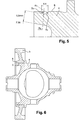
- the degassing forms are generally circular, as on the figure 2 .
- a closed angle of about 60 ° presents risks of cracks at the end of the bead, which are favored by the sharp angles at the end of the weld.
- a more closed angle ( figure 4 ), generates a concentration of stresses at the level of the form, which presents more risks of rupture in fatigue.
- the object of the present invention is to achieve a form of degassing of a differential crown weld bead on its housing, avoiding both fatigue failure of the housing and cracking by the effect of notches at the end of the bead.
- the cutouts of the degassing form in the mass of the case and the crown have an angle greater than 90 ° between the connecting surface and the plane tangent to the entry of the cutout, and a radius significantly greater curvature at the bottom of the cutout than in the transition zones between them and the entrance to the cutout.
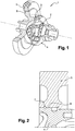
- the diagram of the figure 1 partly shows the internal mechanism 2 of a differential 1, with the planet axle 3, inside the housing 4.
- the housing 4 carries a crown 5 with helical teeth.
- the cut part of the case 3 and of the crown 4 shows their connection zone 6. No form of degassing is shown in this figure.
- the figure 2 is a partial section through another differential, at the level of the connection zone 6 between the case 4 and the crown 5.
- This connection has a circular degassing shape 7, cut from the mass of the case 4 and that of the crown 5 .
- the proposal illustrated by figure 5 is to produce a shape with a face at the end of the weld having an angularity greater than 90 ° between the connecting plane and the entry of the cutout, and to integrate a high radius (for example of 8 mm) at the bottom of the welding, in order to reduce the stress concentration coefficient and therefore to reduce the stresses.
- the cutouts 7a have an angle ⁇ greater than 90 ° between the connecting surface 6 and the plane tangent to the entry 7b of the cutout 7c, between them and the entrance to the cutout.
- the radius of curvature at the bottom 7c of the cutouts is approximately 8mm, and the radius of curvature of the cutouts in the transition zones between the bottom 7c and the entrance to the cutout, is about 1mm.
- the width of the form (4.4mm on the figure 5 ) and the height of the face (0.5mm on the figure 5 ) may vary, as well as the value of the radii (R1 and R8).
- the transition radius R1 does not affect the strength because the high stress zone is well concentrated at the bottom of the form.
- the gain in stresses is about 30%.
- the values indicated in this example have only an indicative value, and do not limit the scope of the invention.
- the figure 6 shows a complete differential, with the substantially cylindrical connecting surface 6 between an outer face of the housing 4 and an inner face of the crown 5.
- the degassing hollow form 7 consists of two cutouts 7a made opposite in the mass of the case and that of the crown on either side of their connecting surface.
Landscapes
- Engineering & Computer Science (AREA)
- General Engineering & Computer Science (AREA)
- Mechanical Engineering (AREA)
- General Details Of Gearings (AREA)
- Retarders (AREA)
Description
- La présente invention se rapporte aux différentiels de transmission, notamment de véhicules automobiles.
- Plus précisément, elle a pour objet une liaison soudée entre une couronne de différentiel et son boîtier, présentant une surface de liaison sensiblement cylindrique entre une face extérieure du boîtier et une face intérieure de la couronne, dans lesquelles sont ménagées une forme creuse de dégazage constituée de deux découpes en vis-à-vis dans la masse du boîtier et celle de de la couronne, de part et d'autre de leur surface de liaison.
- L'invention a également pour objet un différentiel de transmission comportant un boîtier et une couronne d'entrée soudée sur celui-ci.
- Dans la chaîne cinématique d'un véhicule, le couple provenant du moteur est transmis par une descente de pignons, jusqu'à la couronne de pont du différentiel. Le boîtier du différentiel est lié à la couronne de pont. Il transmet le couple au mécanisme interne du différentiel (satellites et planétaires), par l'axe de satellites.
- Les couronnes de différentiel peuvent être liées au boîtier de diverses façons, notamment par frettage/sertissage, par vissage, ou par soudage. Dans une liaison par soudage, il est souvent avantageux de dégager une forme, dite forme de dégazage, entre les deux pièces soudées, pour améliorer la qualité de la soudure. Entre un boîtier de différentiel et la couronne de pont, on dégage ainsi une forme dans la masse des deux pièces, pour l'évacuation des gaz émis lors de l'opération de soudure. Sans cette forme, la soudure est irrégulière, car il se forme un bourrelet dû à une surpression faisant ressortir le métal, ce qui réduit la tenue en fatigue de la liaison.
- Sur les différentiels de boîte de vitesses transversale, la denture de la couronne est généralement de type hélicoïdal à axes parallèles. L'angle d'hélice des dentures de la couronne et de son pignon d'attaque, génère des efforts axiaux dirigés à droite ou à gauche sur les dentures, selon que le moteur entraine le véhicule (tirage) ou que le véhicule entraine le moteur (rétro). La forme de dégazage est alors soumise alternativement à des efforts de traction et de compression importants. Elle doit être dessinée de manière à éviter à la fois la rupture en fatigue du boîtier de différentiel et/ou de la couronne, et sa fissuration par effet d'entailles en bout de cordon de soudure.
- La publication
EP 2 538 119 décrit une liaison soudée entre une couronne et son boîtier. Cette liaison présente une surface de liaison sensiblement cylindrique entre une face extérieure du boîtier et une face intérieure de la couronne, dans lesquelles sont ménagées une forme creuse de dégazage constituées de deux découpes en vis-à-vis dans la masse du boîtier et celle de la couronne. - Selon cette disposition connue, les formes de dégazage sont globalement circulaires, comme sur la
figure 2 . En faisant évoluer l'angle entre la forme et l'axe du plan de joint de soudure, on obtient des formes de dégazage différentes, comme sur lafigure 3 ou 4 . Un angle fermé d'environ 60° (figure 3 ), présente des risques de fissures en bout de cordon, qui sont favorisés par les angles vifs en bout de soudure. Toutefois, un angle plus fermé (figure 4 ), génère une concentration de contraintes au niveau de la forme, qui présente plus de risques de rupture en fatigue. - La présente invention a pour but de réaliser une forme de dégazage d'un cordon de soudure de couronne de différentiel sur son boîtier, évitant à la fois la rupture en fatigue du boîtier et la fissuration par effet d'entailles en bout de cordon.
- Dans ce but, elle propose que les découpes de la forme de dégazage dans la masse du boîtier et de la couronne présentent un angle supérieur à 90° entre la surface de liaison et le plan tangent à l'entrée de la découpe, et un rayon de courbure nettement plus important en fond de découpe que dans les zones de transition entre celles-ci et l'entrée de la découpe.
- La présente invention sera mieux comprise à la lecture de la description suivante d'un mode de réalisation non limitatif de celle-ci, en se reportant aux dessins annexés, sur lesquels :
- la
figure 1 est une vue partiellement éclatée et coupée d'un différentiel à couronne soudée, - la
figure 2 montre une forme de dégazage circulaire, - les
figures 3 et 4 illustrent des évolutions possibles de celle-ci, - la
figure 5 représente la forme de dégazage proposée sur le boîtier du différentiel, et - la
figure 6 représente la forme de dégazage complète avec la couronne soudée sur le boîtier. - Le schéma de la
figure 1 fait apparaître en partie le mécanisme interne 2 d'un différentiel 1, avec l'axe de satellites 3, à l'intérieur du boîtier 4. Le boîtier 4 porte une couronne 5 à denture hélicoïdale. La partie coupée du boîtier 3 et de la couronne 4 met en évidence leur zone de liaison 6. Aucune forme de dégazage n'est représentée sur cette figure. - La
figure 2 est une coupe partielle d'un autre différentiel, au niveau de la zone de liaison 6 entre le boîtier 4 et la couronne 5. Cette liaison présente une forme de dégazage circulaire 7, découpée dans la masse du boîtier 4 et celle de la couronne 5. - Sur les exemples des
figures 3 et 4 , on n'a représenté qu'une partie d'un boîtier de différentiel 4, avec la partie d'une forme de dégazage 7a découpée dans la masse de celui-ci. L'évolution de ces deux exemples par rapport à lafigure 2 , concerne l'angle α du plan de liaison 8a avec la tangente 7b à l'entrée de la découpe de forme dans la masse. Comme indiqué plus haut, un angle α fermé d'environ 60° (figure 3 ) présente des risques de fissures en bout de cordon, qui sont favorisés par les angles vifs en bout de soudure. Un angle α plus ouvert (figure 4 ), génère une concentration de contraintes au niveau de la forme, qui présente des risques élevés de rupture en fatigue. - La proposition illustrée par la
figure 5 , est de réaliser une forme avec une face en bout de soudure ayant une angularité supérieure à 90° entre le plan de liaison et l'entrée de la découpe, et d'intégrer un rayon élevé (par exemple de 8 mm) au fond de la soudure, afin de diminuer le coefficient de concentration de contraintes et donc de diminuer les contraintes. Les découpes 7a présentent un angle α supérieur à 90° entre la surface de liaison 6 et le plan tangent à l'entrée 7b de la découpe 7c, entre celles-ci et l'entrée de la découpe. Dans cet exemple de réalisation non limitatif, le rayon de courbure au fond 7c des découpes est d'environ 8mm, et le rayon de courbure des découpes dans les zones de transition entre le fond 7c et l'entrée de la découpe, est d'environ 1mm. Sans sortir du cadre de l'invention, la largeur de la forme (4,4mm sur lafigure 5 ) et la hauteur de la face (0,5mm sur lafigure 5 ) peuvent varier, ainsi que la valeur des rayons (R1 et R8). - Entre l'entrée et le fond 7c des découpes 7a, le rayon de transition R1 ne remet pas en cause la tenue car la zone de forte contrainte est bien concentrée au fond de la forme. Entre ce nouveau dessin et la forme de la
figure 4 , le gain en contraintes est d'environ 30%. Les valeurs indiquées sur cet exemple, n'ont cependant qu'une valeur indicative, et ne limitent pas la portée de l'invention. - La
figure 6 , montre un différentiel complet, avec la surface de liaison 6 sensiblement cylindrique entre une face extérieure du boîtier 4 et une face intérieure de la couronne 5. Conformément à l'invention, la forme creuse de dégazage 7, est constituée de deux découpes 7a ménagées en vis-à-vis dans la masse du boîtier et celle de de la couronne de part et d'autre de leur surface de liaison. Sur cette figure, on retrouve le boîtier 4 et la couronne 5, soudées avec la forme de dégazage proposée aménagée côté boîtier et côté couronne, sur leur surface de liaison 6. - En conclusion, l'invention propose une forme de dégazage qui respecte deux points importants :
- être perpendiculaire à l'axe de la soudure afin d'éviter de générer de fissure par effet d'entailles en bout de cordon de soudure, et
- ne pas générer de concentration de contraintes afin de résister aux efforts axiaux de la denture en tirage ou en rétro, qui viennent mettre en traction la forme de dégazage.
- Les avantages principaux de cette solution sont :
- la réduction du risque de fissure par effet d'entailles en bout de cordon de soudure, et
- la réduction du coefficient de concentration de contraintes au niveau de la forme de dégazage afin de résister aux efforts axiaux de la denture qui, en tirage ou en rétro, viennent mettre en traction la forme de dégazage. Le différentiel a ainsi plus de capacité en couple, pour une même définition technique de soudure.
Claims (4)
- Liaison soudée entre une couronne de différentiel (5) et son boîtier (4), présentant une surface de liaison (6) sensiblement cylindrique entre une face extérieure du boîtier (4) et une face intérieure de la couronne (5), dans lesquelles sont ménagées une forme creuse de dégazage (7) constituée de deux découpes (7a) en vis-à-vis dans la masse du boîtier (4) et celle de de la couronne (5) de part et d'autre de leur surface de liaison, caractérisée en ce que les découpes (7a) présentent un angle (α) supérieur à 90° entre la surface de liaison (6) et le plan tangent à l'entrée (7b) de la découpe (7a), et un rayon de courbure plus important en fond (7c) de découpe (7a), que dans les zones de transition entre celles-ci et l'entrée de la découpe (7a).
- Liaison soudée selon la revendication 1, caractérisée en ce que le rayon de courbure au fond (7c) des découpes (7a) est d'environ 8mm.
- Liaison soudée selon la revendication 1 ou 2, caractérisée en ce que le rayon de courbure des découpes (7a) dans les zones de transition entre le fond (7c) et l'entrée de la découpe (7a), est d'environ 1mm.
- Différentiel de transmission (1) comportant un boîtier (4) et une couronne d'entrée (5) soudée sur celui-ci, caractérisée en ce que la liaison entre ces deux éléments (4, 5) est conforme à la revendication 1, 2 ou 3.
Applications Claiming Priority (2)
| Application Number | Priority Date | Filing Date | Title |
|---|---|---|---|
| FR1556824A FR3039242B1 (fr) | 2015-07-20 | 2015-07-20 | Liaison soudee entre une couronne de differentiel et son boitier |
| PCT/FR2016/051518 WO2017013321A1 (fr) | 2015-07-20 | 2016-06-21 | Liaison soudee entre une couronne de differentiel et son boitier |
Publications (2)
| Publication Number | Publication Date |
|---|---|
| EP3325848A1 EP3325848A1 (fr) | 2018-05-30 |
| EP3325848B1 true EP3325848B1 (fr) | 2021-03-10 |
Family
ID=54329738
Family Applications (1)
| Application Number | Title | Priority Date | Filing Date |
|---|---|---|---|
| EP16742333.4A Active EP3325848B1 (fr) | 2015-07-20 | 2016-06-21 | Liaison soudee entre une couronne de differentiel et son boitier |
Country Status (4)
| Country | Link |
|---|---|
| EP (1) | EP3325848B1 (fr) |
| CN (1) | CN108027035A (fr) |
| FR (1) | FR3039242B1 (fr) |
| WO (1) | WO2017013321A1 (fr) |
Families Citing this family (2)
| Publication number | Priority date | Publication date | Assignee | Title |
|---|---|---|---|---|
| FR3064325B1 (fr) * | 2017-03-24 | 2022-08-19 | Renault Sas | Boitier de de differentiel de transmission pour vehicule et differentiel de transmission |
| DE102022127223B4 (de) * | 2022-10-18 | 2024-10-10 | Dr. Ing. H.C. F. Porsche Aktiengesellschaft | Differentialgetriebe für ein Kraftfahrzeug mit einem durch eine Schweißnaht mit Entlastungsnut an einem Käfig angeordneten Zahnrad |
Family Cites Families (10)
| Publication number | Priority date | Publication date | Assignee | Title |
|---|---|---|---|---|
| FR2830593B1 (fr) * | 2001-10-04 | 2004-02-06 | Peugeot Citroen Automobiles Sa | Differentiel de transmission de couple pour vehicules automobiles |
| JP2005081351A (ja) * | 2003-09-04 | 2005-03-31 | Aisin Aw Co Ltd | 摩擦圧接部材およびこれを備えた差動装置 |
| FR2864189B1 (fr) * | 2003-12-23 | 2007-01-26 | Renault Sas | Differentiel avec element de friction decouvrant partiellement la pignonerie |
| DE102005023230B4 (de) * | 2005-05-04 | 2010-10-07 | Bayerische Motoren Werke Aktiengesellschaft | Verfahren zum Verschweißen eines Tellerrads mit einem Ausgleichsgehäuse eines Getriebes |
| JP4826651B2 (ja) * | 2009-04-09 | 2011-11-30 | トヨタ自動車株式会社 | ディファレンシャルギヤ |
| JP5206656B2 (ja) * | 2009-12-03 | 2013-06-12 | トヨタ自動車株式会社 | 車両用差動歯車装置 |
| US9239104B2 (en) * | 2010-01-22 | 2016-01-19 | Toyota Jidosha Kabushiki Kaisha | Welded structure and welding method |
| DE102010054655B4 (de) * | 2010-09-15 | 2012-08-09 | Sona Blw Präzisionsschmiede Gmbh | Differential für Kraftfahrzeuge |
| JP5327394B2 (ja) * | 2010-09-20 | 2013-10-30 | トヨタ自動車株式会社 | 溶接構造 |
| CA2780125C (fr) * | 2011-06-22 | 2016-10-04 | Metal Forming & Coining Corporation | Ensemble carter de differentiel forme par fluotournage |
-
2015
- 2015-07-20 FR FR1556824A patent/FR3039242B1/fr not_active Expired - Fee Related
-
2016
- 2016-06-21 CN CN201680040920.3A patent/CN108027035A/zh active Pending
- 2016-06-21 EP EP16742333.4A patent/EP3325848B1/fr active Active
- 2016-06-21 WO PCT/FR2016/051518 patent/WO2017013321A1/fr not_active Ceased
Non-Patent Citations (1)
| Title |
|---|
| None * |
Also Published As
| Publication number | Publication date |
|---|---|
| EP3325848A1 (fr) | 2018-05-30 |
| WO2017013321A1 (fr) | 2017-01-26 |
| FR3039242A1 (fr) | 2017-01-27 |
| CN108027035A (zh) | 2018-05-11 |
| FR3039242B1 (fr) | 2017-07-14 |
Similar Documents
| Publication | Publication Date | Title |
|---|---|---|
| EP3551484B1 (fr) | Dispositif de liaison entre un longeron en aluminium de véhicule et un bras de suspension | |
| EP2246517A1 (fr) | Dispositif de transmission viscoélastique d'un actionneur d'un volet roulant | |
| EP0840867A1 (fr) | Dispositif de raccordement etanche entre un embout de tube rigide et un tuyau souple et procede de fabrication d'un tel dispositif | |
| EP3325848B1 (fr) | Liaison soudee entre une couronne de differentiel et son boitier | |
| EP3039304B1 (fr) | Elément de fixation fileté | |
| WO2013153339A1 (fr) | Accouplement d'arbres par cannelures a profil evolutif | |
| EP3555412B1 (fr) | Joint fileté pour composant tubulaire | |
| FR3006943A1 (fr) | Procede de realisation d'un berceau avant de vehicule, et berceau avant de vehicule obtenu par ce procede. | |
| EP0122853B1 (fr) | Axe de volant pour colonne de direction de véhicule automobile | |
| EP1800897A1 (fr) | Roue comprenant une jante, un moyeu, et un dispositif de raccordement de la jante au moyeu | |
| FR2995862A1 (fr) | Traverse de planche de bord de vehicule automobile constituee par deux tubes et une jambe de force en materiau composite | |
| EP0737114B1 (fr) | Procede de retreint | |
| FR3002297A1 (fr) | Procede de realisation par hydroformage d'une biellette de direction allegee | |
| FR2756337A1 (fr) | Corps de moyeu pour embrayages, notamment des embrayages a friction dans des vehicules automobiles | |
| FR2819035A1 (fr) | Clapet a joint serti et procede de fabrication d'un tel clapet | |
| FR2805869A1 (fr) | Manchon antivibratoire, bielle comportant un tel manchon, et procede de fabrication | |
| FR2828914A1 (fr) | Dispositif d'assemblage | |
| EP3015318B1 (fr) | Dispositif perfectionné d'absorption de l'énergie d'un choc, notamment pour un véhicule automobile | |
| EP1853444B1 (fr) | Essieu souple comprenant une traverse dont les extremites presentent une zone de moindre rigidite, traverse, procede de fabrication et vehicule correspondant | |
| FR2990256A1 (fr) | Emetteur hydraulique a triple chambre pour commande d'embrayage et procedes associes | |
| EP1250538B1 (fr) | Securisation d'articulation elastique | |
| EP2452862B1 (fr) | Carter de direction de véhicule automobile à section variable | |
| EP1768863B1 (fr) | Element de liaison renforce entre un bras longitudinal d'essieu et une barre anti-devers, essieu, vehicule et procede de fabrication correspondants | |
| FR3018328A3 (fr) | Differentiel pour vehicule automobile avec dispositif de maintien en position de l'axe porte-satellite | |
| FR3120415A1 (fr) | Elément tubulaire fileté à segment |
Legal Events
| Date | Code | Title | Description |
|---|---|---|---|
| STAA | Information on the status of an ep patent application or granted ep patent |
Free format text: STATUS: THE INTERNATIONAL PUBLICATION HAS BEEN MADE |
|
| PUAI | Public reference made under article 153(3) epc to a published international application that has entered the european phase |
Free format text: ORIGINAL CODE: 0009012 |
|
| STAA | Information on the status of an ep patent application or granted ep patent |
Free format text: STATUS: REQUEST FOR EXAMINATION WAS MADE |
|
| 17P | Request for examination filed |
Effective date: 20171213 |
|
| AK | Designated contracting states |
Kind code of ref document: A1 Designated state(s): AL AT BE BG CH CY CZ DE DK EE ES FI FR GB GR HR HU IE IS IT LI LT LU LV MC MK MT NL NO PL PT RO RS SE SI SK SM TR |
|
| AX | Request for extension of the european patent |
Extension state: BA ME |
|
| DAV | Request for validation of the european patent (deleted) | ||
| DAX | Request for extension of the european patent (deleted) | ||
| STAA | Information on the status of an ep patent application or granted ep patent |
Free format text: STATUS: EXAMINATION IS IN PROGRESS |
|
| 17Q | First examination report despatched |
Effective date: 20191121 |
|
| GRAP | Despatch of communication of intention to grant a patent |
Free format text: ORIGINAL CODE: EPIDOSNIGR1 |
|
| STAA | Information on the status of an ep patent application or granted ep patent |
Free format text: STATUS: GRANT OF PATENT IS INTENDED |
|
| INTG | Intention to grant announced |
Effective date: 20200930 |
|
| GRAS | Grant fee paid |
Free format text: ORIGINAL CODE: EPIDOSNIGR3 |
|
| GRAA | (expected) grant |
Free format text: ORIGINAL CODE: 0009210 |
|
| STAA | Information on the status of an ep patent application or granted ep patent |
Free format text: STATUS: THE PATENT HAS BEEN GRANTED |
|
| AK | Designated contracting states |
Kind code of ref document: B1 Designated state(s): AL AT BE BG CH CY CZ DE DK EE ES FI FR GB GR HR HU IE IS IT LI LT LU LV MC MK MT NL NO PL PT RO RS SE SI SK SM TR |
|
| REG | Reference to a national code |
Ref country code: GB Ref legal event code: FG4D Free format text: NOT ENGLISH |
|
| REG | Reference to a national code |
Ref country code: AT Ref legal event code: REF Ref document number: 1370152 Country of ref document: AT Kind code of ref document: T Effective date: 20210315 Ref country code: CH Ref legal event code: EP |
|
| REG | Reference to a national code |
Ref country code: DE Ref legal event code: R096 Ref document number: 602016054014 Country of ref document: DE |
|
| REG | Reference to a national code |
Ref country code: IE Ref legal event code: FG4D Free format text: LANGUAGE OF EP DOCUMENT: FRENCH |
|
| REG | Reference to a national code |
Ref country code: LT Ref legal event code: MG9D |
|
| PG25 | Lapsed in a contracting state [announced via postgrant information from national office to epo] |
Ref country code: HR Free format text: LAPSE BECAUSE OF FAILURE TO SUBMIT A TRANSLATION OF THE DESCRIPTION OR TO PAY THE FEE WITHIN THE PRESCRIBED TIME-LIMIT Effective date: 20210310 Ref country code: FI Free format text: LAPSE BECAUSE OF FAILURE TO SUBMIT A TRANSLATION OF THE DESCRIPTION OR TO PAY THE FEE WITHIN THE PRESCRIBED TIME-LIMIT Effective date: 20210310 Ref country code: GR Free format text: LAPSE BECAUSE OF FAILURE TO SUBMIT A TRANSLATION OF THE DESCRIPTION OR TO PAY THE FEE WITHIN THE PRESCRIBED TIME-LIMIT Effective date: 20210611 Ref country code: NO Free format text: LAPSE BECAUSE OF FAILURE TO SUBMIT A TRANSLATION OF THE DESCRIPTION OR TO PAY THE FEE WITHIN THE PRESCRIBED TIME-LIMIT Effective date: 20210610 Ref country code: LT Free format text: LAPSE BECAUSE OF FAILURE TO SUBMIT A TRANSLATION OF THE DESCRIPTION OR TO PAY THE FEE WITHIN THE PRESCRIBED TIME-LIMIT Effective date: 20210310 Ref country code: BG Free format text: LAPSE BECAUSE OF FAILURE TO SUBMIT A TRANSLATION OF THE DESCRIPTION OR TO PAY THE FEE WITHIN THE PRESCRIBED TIME-LIMIT Effective date: 20210610 |
|
| REG | Reference to a national code |
Ref country code: AT Ref legal event code: MK05 Ref document number: 1370152 Country of ref document: AT Kind code of ref document: T Effective date: 20210310 |
|
| REG | Reference to a national code |
Ref country code: NL Ref legal event code: MP Effective date: 20210310 |
|
| PG25 | Lapsed in a contracting state [announced via postgrant information from national office to epo] |
Ref country code: SE Free format text: LAPSE BECAUSE OF FAILURE TO SUBMIT A TRANSLATION OF THE DESCRIPTION OR TO PAY THE FEE WITHIN THE PRESCRIBED TIME-LIMIT Effective date: 20210310 Ref country code: LV Free format text: LAPSE BECAUSE OF FAILURE TO SUBMIT A TRANSLATION OF THE DESCRIPTION OR TO PAY THE FEE WITHIN THE PRESCRIBED TIME-LIMIT Effective date: 20210310 Ref country code: RS Free format text: LAPSE BECAUSE OF FAILURE TO SUBMIT A TRANSLATION OF THE DESCRIPTION OR TO PAY THE FEE WITHIN THE PRESCRIBED TIME-LIMIT Effective date: 20210310 |
|
| PG25 | Lapsed in a contracting state [announced via postgrant information from national office to epo] |
Ref country code: NL Free format text: LAPSE BECAUSE OF FAILURE TO SUBMIT A TRANSLATION OF THE DESCRIPTION OR TO PAY THE FEE WITHIN THE PRESCRIBED TIME-LIMIT Effective date: 20210310 |
|
| PG25 | Lapsed in a contracting state [announced via postgrant information from national office to epo] |
Ref country code: EE Free format text: LAPSE BECAUSE OF FAILURE TO SUBMIT A TRANSLATION OF THE DESCRIPTION OR TO PAY THE FEE WITHIN THE PRESCRIBED TIME-LIMIT Effective date: 20210310 Ref country code: CZ Free format text: LAPSE BECAUSE OF FAILURE TO SUBMIT A TRANSLATION OF THE DESCRIPTION OR TO PAY THE FEE WITHIN THE PRESCRIBED TIME-LIMIT Effective date: 20210310 Ref country code: AT Free format text: LAPSE BECAUSE OF FAILURE TO SUBMIT A TRANSLATION OF THE DESCRIPTION OR TO PAY THE FEE WITHIN THE PRESCRIBED TIME-LIMIT Effective date: 20210310 Ref country code: SM Free format text: LAPSE BECAUSE OF FAILURE TO SUBMIT A TRANSLATION OF THE DESCRIPTION OR TO PAY THE FEE WITHIN THE PRESCRIBED TIME-LIMIT Effective date: 20210310 |
|
| PG25 | Lapsed in a contracting state [announced via postgrant information from national office to epo] |
Ref country code: IS Free format text: LAPSE BECAUSE OF FAILURE TO SUBMIT A TRANSLATION OF THE DESCRIPTION OR TO PAY THE FEE WITHIN THE PRESCRIBED TIME-LIMIT Effective date: 20210710 Ref country code: PL Free format text: LAPSE BECAUSE OF FAILURE TO SUBMIT A TRANSLATION OF THE DESCRIPTION OR TO PAY THE FEE WITHIN THE PRESCRIBED TIME-LIMIT Effective date: 20210310 Ref country code: PT Free format text: LAPSE BECAUSE OF FAILURE TO SUBMIT A TRANSLATION OF THE DESCRIPTION OR TO PAY THE FEE WITHIN THE PRESCRIBED TIME-LIMIT Effective date: 20210712 Ref country code: SK Free format text: LAPSE BECAUSE OF FAILURE TO SUBMIT A TRANSLATION OF THE DESCRIPTION OR TO PAY THE FEE WITHIN THE PRESCRIBED TIME-LIMIT Effective date: 20210310 Ref country code: RO Free format text: LAPSE BECAUSE OF FAILURE TO SUBMIT A TRANSLATION OF THE DESCRIPTION OR TO PAY THE FEE WITHIN THE PRESCRIBED TIME-LIMIT Effective date: 20210310 |
|
| REG | Reference to a national code |
Ref country code: DE Ref legal event code: R097 Ref document number: 602016054014 Country of ref document: DE |
|
| PLBE | No opposition filed within time limit |
Free format text: ORIGINAL CODE: 0009261 |
|
| STAA | Information on the status of an ep patent application or granted ep patent |
Free format text: STATUS: NO OPPOSITION FILED WITHIN TIME LIMIT |
|
| PG25 | Lapsed in a contracting state [announced via postgrant information from national office to epo] |
Ref country code: DK Free format text: LAPSE BECAUSE OF FAILURE TO SUBMIT A TRANSLATION OF THE DESCRIPTION OR TO PAY THE FEE WITHIN THE PRESCRIBED TIME-LIMIT Effective date: 20210310 Ref country code: MC Free format text: LAPSE BECAUSE OF FAILURE TO SUBMIT A TRANSLATION OF THE DESCRIPTION OR TO PAY THE FEE WITHIN THE PRESCRIBED TIME-LIMIT Effective date: 20210310 Ref country code: AL Free format text: LAPSE BECAUSE OF FAILURE TO SUBMIT A TRANSLATION OF THE DESCRIPTION OR TO PAY THE FEE WITHIN THE PRESCRIBED TIME-LIMIT Effective date: 20210310 Ref country code: ES Free format text: LAPSE BECAUSE OF FAILURE TO SUBMIT A TRANSLATION OF THE DESCRIPTION OR TO PAY THE FEE WITHIN THE PRESCRIBED TIME-LIMIT Effective date: 20210310 |
|
| REG | Reference to a national code |
Ref country code: CH Ref legal event code: PL |
|
| 26N | No opposition filed |
Effective date: 20211213 |
|
| PG25 | Lapsed in a contracting state [announced via postgrant information from national office to epo] |
Ref country code: SI Free format text: LAPSE BECAUSE OF FAILURE TO SUBMIT A TRANSLATION OF THE DESCRIPTION OR TO PAY THE FEE WITHIN THE PRESCRIBED TIME-LIMIT Effective date: 20210310 |
|
| REG | Reference to a national code |
Ref country code: BE Ref legal event code: MM Effective date: 20210630 |
|
| PG25 | Lapsed in a contracting state [announced via postgrant information from national office to epo] |
Ref country code: LU Free format text: LAPSE BECAUSE OF NON-PAYMENT OF DUE FEES Effective date: 20210621 |
|
| PG25 | Lapsed in a contracting state [announced via postgrant information from national office to epo] |
Ref country code: LI Free format text: LAPSE BECAUSE OF NON-PAYMENT OF DUE FEES Effective date: 20210630 Ref country code: IT Free format text: LAPSE BECAUSE OF FAILURE TO SUBMIT A TRANSLATION OF THE DESCRIPTION OR TO PAY THE FEE WITHIN THE PRESCRIBED TIME-LIMIT Effective date: 20210310 Ref country code: IE Free format text: LAPSE BECAUSE OF NON-PAYMENT OF DUE FEES Effective date: 20210621 Ref country code: CH Free format text: LAPSE BECAUSE OF NON-PAYMENT OF DUE FEES Effective date: 20210630 |
|
| PG25 | Lapsed in a contracting state [announced via postgrant information from national office to epo] |
Ref country code: IS Free format text: LAPSE BECAUSE OF FAILURE TO SUBMIT A TRANSLATION OF THE DESCRIPTION OR TO PAY THE FEE WITHIN THE PRESCRIBED TIME-LIMIT Effective date: 20210710 |
|
| PG25 | Lapsed in a contracting state [announced via postgrant information from national office to epo] |
Ref country code: BE Free format text: LAPSE BECAUSE OF NON-PAYMENT OF DUE FEES Effective date: 20210630 |
|
| PG25 | Lapsed in a contracting state [announced via postgrant information from national office to epo] |
Ref country code: CY Free format text: LAPSE BECAUSE OF FAILURE TO SUBMIT A TRANSLATION OF THE DESCRIPTION OR TO PAY THE FEE WITHIN THE PRESCRIBED TIME-LIMIT Effective date: 20210310 |
|
| P01 | Opt-out of the competence of the unified patent court (upc) registered |
Effective date: 20230608 |
|
| PG25 | Lapsed in a contracting state [announced via postgrant information from national office to epo] |
Ref country code: HU Free format text: LAPSE BECAUSE OF FAILURE TO SUBMIT A TRANSLATION OF THE DESCRIPTION OR TO PAY THE FEE WITHIN THE PRESCRIBED TIME-LIMIT; INVALID AB INITIO Effective date: 20160621 |
|
| PG25 | Lapsed in a contracting state [announced via postgrant information from national office to epo] |
Ref country code: MK Free format text: LAPSE BECAUSE OF FAILURE TO SUBMIT A TRANSLATION OF THE DESCRIPTION OR TO PAY THE FEE WITHIN THE PRESCRIBED TIME-LIMIT Effective date: 20210310 |
|
| PG25 | Lapsed in a contracting state [announced via postgrant information from national office to epo] |
Ref country code: TR Free format text: LAPSE BECAUSE OF FAILURE TO SUBMIT A TRANSLATION OF THE DESCRIPTION OR TO PAY THE FEE WITHIN THE PRESCRIBED TIME-LIMIT Effective date: 20210310 |
|
| PGFP | Annual fee paid to national office [announced via postgrant information from national office to epo] |
Ref country code: GB Payment date: 20240621 Year of fee payment: 9 |
|
| PG25 | Lapsed in a contracting state [announced via postgrant information from national office to epo] |
Ref country code: MT Free format text: LAPSE BECAUSE OF FAILURE TO SUBMIT A TRANSLATION OF THE DESCRIPTION OR TO PAY THE FEE WITHIN THE PRESCRIBED TIME-LIMIT Effective date: 20210310 |
|
| PGFP | Annual fee paid to national office [announced via postgrant information from national office to epo] |
Ref country code: DE Payment date: 20250618 Year of fee payment: 10 |
|
| PGFP | Annual fee paid to national office [announced via postgrant information from national office to epo] |
Ref country code: FR Payment date: 20250625 Year of fee payment: 10 |
|
| GBPC | Gb: european patent ceased through non-payment of renewal fee |
Effective date: 20250621 |
|
| PG25 | Lapsed in a contracting state [announced via postgrant information from national office to epo] |
Ref country code: GB Free format text: LAPSE BECAUSE OF NON-PAYMENT OF DUE FEES Effective date: 20250621 |