EP3326249B1 - Anordnung aus einem dachaufbau und einem befestigunssystem für die befestigung des dachaufbaus in einem ausschnitt auf dem dach eines schaltschranks - Google Patents
Anordnung aus einem dachaufbau und einem befestigunssystem für die befestigung des dachaufbaus in einem ausschnitt auf dem dach eines schaltschranks Download PDFInfo
- Publication number
- EP3326249B1 EP3326249B1 EP16754172.1A EP16754172A EP3326249B1 EP 3326249 B1 EP3326249 B1 EP 3326249B1 EP 16754172 A EP16754172 A EP 16754172A EP 3326249 B1 EP3326249 B1 EP 3326249B1
- Authority
- EP
- European Patent Office
- Prior art keywords
- roof structure
- arrangement
- roof
- bolt
- pretensioning device
- Prior art date
- Legal status (The legal status is an assumption and is not a legal conclusion. Google has not performed a legal analysis and makes no representation as to the accuracy of the status listed.)
- Active
Links
Images

Classifications
-
- H—ELECTRICITY
- H02—GENERATION; CONVERSION OR DISTRIBUTION OF ELECTRIC POWER
- H02B—BOARDS, SUBSTATIONS OR SWITCHING ARRANGEMENTS FOR THE SUPPLY OR DISTRIBUTION OF ELECTRIC POWER
- H02B1/00—Frameworks, boards, panels, desks, casings; Details of substations or switching arrangements
- H02B1/01—Frameworks
- H02B1/012—Details of mechanical connections
-
- F—MECHANICAL ENGINEERING; LIGHTING; HEATING; WEAPONS; BLASTING
- F16—ENGINEERING ELEMENTS AND UNITS; GENERAL MEASURES FOR PRODUCING AND MAINTAINING EFFECTIVE FUNCTIONING OF MACHINES OR INSTALLATIONS; THERMAL INSULATION IN GENERAL
- F16B—DEVICES FOR FASTENING OR SECURING CONSTRUCTIONAL ELEMENTS OR MACHINE PARTS TOGETHER, e.g. NAILS, BOLTS, CIRCLIPS, CLAMPS, CLIPS OR WEDGES; JOINTS OR JOINTING
- F16B2/00—Friction-grip releasable fastenings
- F16B2/02—Clamps, i.e. with gripping action effected by positive means other than the inherent resistance to deformation of the material of the fastening
- F16B2/06—Clamps, i.e. with gripping action effected by positive means other than the inherent resistance to deformation of the material of the fastening external, i.e. with contracting action
- F16B2/065—Clamps, i.e. with gripping action effected by positive means other than the inherent resistance to deformation of the material of the fastening external, i.e. with contracting action using screw-thread elements
-
- H—ELECTRICITY
- H02—GENERATION; CONVERSION OR DISTRIBUTION OF ELECTRIC POWER
- H02B—BOARDS, SUBSTATIONS OR SWITCHING ARRANGEMENTS FOR THE SUPPLY OR DISTRIBUTION OF ELECTRIC POWER
- H02B1/00—Frameworks, boards, panels, desks, casings; Details of substations or switching arrangements
- H02B1/26—Casings; Parts thereof or accessories therefor
- H02B1/30—Cabinet-type casings; Parts thereof or accessories therefor
-
- H—ELECTRICITY
- H02—GENERATION; CONVERSION OR DISTRIBUTION OF ELECTRIC POWER
- H02B—BOARDS, SUBSTATIONS OR SWITCHING ARRANGEMENTS FOR THE SUPPLY OR DISTRIBUTION OF ELECTRIC POWER
- H02B1/00—Frameworks, boards, panels, desks, casings; Details of substations or switching arrangements
- H02B1/56—Cooling; Ventilation
- H02B1/565—Cooling; Ventilation for cabinets
Definitions
- the invention relates to an arrangement of a roof structure, in particular a cooling device, and a fastening system for fastening the roof structure in a cutout on a roof of a cabinet.
- a roof structure in particular a cooling device
- a fastening system for fastening the roof structure in a cutout on a roof of a cabinet.
- Such an arrangement is known from DE 41 10 323 C1 known.
- Similar arrangements also show the EP 0 594 542 A1 and the DE 82 05 341 U1 ,
- the fastening system comprises a pretensioning device connected to the roof structure and a fastening clip, wherein the fastening clip has a fixed end, via which the fastening clip is fixed on an inner side of the roof structure, and an end movable relative to the fixed end, on which the pretensioning device engages, so that a radius of curvature of the mounting bracket on the biasing device is adjustable, wherein in a first position of the biasing device, the mounting bracket is adapted to engage under a boundary of a section and so define the roof structure on the one cabinet, and in a second Position of the biasing device, the mounting bracket is adapted to release the cutout, wherein the biasing device extends from an outer side of the roof structure through the roof structure through to an inner side of the roof structure, on the outside a first drive for a tool and on the inside a second drive for a tool.
- the first and the second drive can be, for example, screw drives, for example a Torx25 drive.
- a fastening system in which for the installation of the roof structure at a cutout in the roof of a cabinet, the roof structure can initially be done from the inside of the cabinet, which insofar a relief for the user is achieved because it requires no ladder or the like. If the control cabinet fills with components over time, or if the installation space of the control cabinet is so far occupied that the assembly or disassembly of the roof structure from the inside is no longer possible, the fastener previously actuated from the interior of the control cabinet can also be used from the outside of the control cabinet, more precisely from the roof side of the cabinet, are operated, the entire scope of functions of the fastening system is maintained.
- the biasing means may comprise a first pin with the first drive for a tool and a second pin with the second drive for a tool, wherein the bolts are rotatably connected to each other.
- the bolts may have complementary threads over which the bolts engage with each other, wherein the bolts for the rotationally fixed connection can be designed with each other. For example, they can be glued.
- one of the bolts has a bolt shank with an external thread, with which the bolt passes through a passage between an inside of the bolt Roof assembly and an outer side of the roof construction forming threaded sleeve extends with complementary internal thread therethrough, wherein the threaded sleeve is connected about its longitudinal axis against rotation with the roof structure.
- the threaded sleeve can thus form a threaded bearing for the bolt shaft, along which this rotationally adjustable different positions can take to adjust the mounting bracket, more precisely, its movable end variable.
- the second bolt may be formed as a sleeve nut, with a screw head having the second drive.
- the mounting bracket may have at the movable end a slot which extends along the mounting bracket in the direction of the fixed end, wherein one of the bolt extends with its bolt shank through the slot and the mounting bracket with an edge region of the slot on a bolt head of the second bolt supports, so that the bolt shaft is guided along the slot when the biasing device is moved between the first and the second position.
- the mounting bracket may be fixed with its fixed end on an inner side of the roof structure vertically above the cutout and spaced from an edge of the cutout on the inside of the roof structure, extending in the further course through the cutout into the cabinet interior and approach the edge of the cutout , In order to ensure the safe pivoting in and out of the mounting bracket, it can be provided that the biasing device is biased by a spring element in the second position.
- the mounting bracket may be formed of a resilient material and preferably made of spring steel, wherein the mounting bracket may further have a bias in the direction of the second position.
- the arrangement according to the invention makes it possible to rework the roof attachment, in particular retighten the attachment system, also at any time after attachment of the roof structure to the roof of the control cabinet.
- This can also be provided that the drive on the cabinet inside and the drive on the cabinet outside are identical, so that correspondingly identical tools can be used for the operation of the drive.
- the roof structure has a peripheral flange, via which the roof structure is placed on a boundary of the cutout of the control cabinet roof, wherein in a region of overlap between the peripheral flange and the edge, a sealing element is arranged, the compression of the biasing device variably adjustable is.
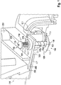
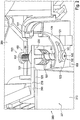
- FIG. 1 illustrated embodiment of a fastening system 100 for attachment of a roof structure 200 in or on a cutout 320 on the roof 310 of a cabinet 300
- the essential components of the fastening system 100, the associated with the roof structure 200 biasing device 110 and the mounting bracket 120, which via the biasing device 110 between a first position of the biasing device in which the mounting bracket 120 engages under a boundary 321 of the cutout 320 and thus defines the roof structure 200 to the control cabinet 300, and a second Position of the biasing device in which the mounting bracket releases the cutout, can be moved back and forth.
- the mounting bracket 120 has a fixed end 121, via which the mounting bracket 120 is fixed to the inside 220 of the roof structure 200.
- the mounting bracket 120 further includes a fixed end 121 opposite the fixed end 122 to which the biasing means acts, so that a curvature of the mounting bracket 120, and thus the position of the movable end 122 with respect to the edge 321 of the cutout 320, by pressing the biasing device 110 can be adjusted.
- the pretensioning device 110 has a bolt 150 with a bolt shaft 151, which in turn has an external thread 152, via which the bolt 150 is screwed into a threaded sleeve 170 with a complementary internal thread 171.
- the threaded sleeve 170 has a polygonal outer contour, via which it is accommodated at least in a form-fitting manner in a receptacle of the roof structure.
- the threaded sleeve 170 just forms a passage through the roof structure 200 and thus connects the outside 210 of the roof structure 200 with the inside 220 of the roof structure 200.
- a coil spring 180 is provided to pivot the mounting bracket 120 upon actuation of the actuator 130 whereby the bolt 150 is displaced relative to the sleeve 170.
- the mounting bracket 120 has at its movable end 122 has a slot 123 in which the shaft 151 of the bolt 150 is guided when the biasing means 110 is actuated to the mounting bracket from the in the FIGS. 1 and 2 shown release position in the in FIG. 3 to shift shown locking position.
- An encircling flange 230 of the roof structure 200 overlaps with an edge region 321 of the roof 310 of the control cabinet, wherein a sealing element 240 is arranged in the overlapping area. It can be seen that the fastening system according to the invention also has the advantage that it makes it possible to variably set the compression of the sealing element 240 and thus the sealing effect thereof via the pretensioning device 110.
- the second bolt 160 is formed as a sleeve nut, which is screwed onto an external thread of the upper bolt 150. With the sleeve nut and the bolt head 161 is fixed to the lower end of the bolt 150 to connect the mounting bracket 120 via the slot 123 with the biasing means.
- the bolt head 161 has just a bearing surface on which the mounting bracket 120 rests with the edge region of the slot 123.
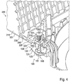
- FIG. 4 shows a further embodiment of the fastening system according to the invention, in which the threaded sleeve 170 is not inserted from above into a plastic tub, but is designed in the manner of a cage nut, which can be laterally inserted into a corresponding receptacle.
- the threaded sleeve is thus preferably rectangular and has a threaded receptacle.
Landscapes
- Engineering & Computer Science (AREA)
- Power Engineering (AREA)
- General Engineering & Computer Science (AREA)
- Mechanical Engineering (AREA)
- Fittings On The Vehicle Exterior For Carrying Loads, And Devices For Holding Or Mounting Articles (AREA)
- Clamps And Clips (AREA)
- Pressure Vessels And Lids Thereof (AREA)
- Connection Of Plates (AREA)
- Patch Boards (AREA)
Priority Applications (1)
| Application Number | Priority Date | Filing Date | Title |
|---|---|---|---|
| PL16754172T PL3326249T3 (pl) | 2015-07-23 | 2016-07-18 | Układ posiadający strukturę dachową oraz system mocowania do mocowania tej struktury dachowej w wycięciu dachu szafy rozdzielczej |
Applications Claiming Priority (2)
| Application Number | Priority Date | Filing Date | Title |
|---|---|---|---|
| DE102015111992.7A DE102015111992A1 (de) | 2015-07-23 | 2015-07-23 | Befestigungssystem für die Befestigung eines Dachaufbaus, insbesondere eines Kühlgeräts, in einem Ausschnitt auf dem Dach eines Schaltschranks |
| PCT/DE2016/100323 WO2017012611A1 (de) | 2015-07-23 | 2016-07-18 | Befestigungssystem für die befestigung eines dachaufbaus in einem ausschnitt auf dem dach eines schaltschranks |
Publications (2)
| Publication Number | Publication Date |
|---|---|
| EP3326249A1 EP3326249A1 (de) | 2018-05-30 |
| EP3326249B1 true EP3326249B1 (de) | 2019-10-30 |
Family
ID=56740724
Family Applications (1)
| Application Number | Title | Priority Date | Filing Date |
|---|---|---|---|
| EP16754172.1A Active EP3326249B1 (de) | 2015-07-23 | 2016-07-18 | Anordnung aus einem dachaufbau und einem befestigunssystem für die befestigung des dachaufbaus in einem ausschnitt auf dem dach eines schaltschranks |
Country Status (6)
| Country | Link |
|---|---|
| US (1) | US10680417B2 (pl) |
| EP (1) | EP3326249B1 (pl) |
| CN (1) | CN107851975B (pl) |
| DE (1) | DE102015111992A1 (pl) |
| PL (1) | PL3326249T3 (pl) |
| WO (1) | WO2017012611A1 (pl) |
Families Citing this family (4)
| Publication number | Priority date | Publication date | Assignee | Title |
|---|---|---|---|---|
| CN108390272A (zh) * | 2018-05-08 | 2018-08-10 | 中科天工电气控股有限公司 | 一种移动配对式成套开关柜 |
| EP3579671B1 (de) * | 2018-06-05 | 2023-03-15 | R. STAHL Schaltgeräte GmbH | Gehäuse der schutzart druckfeste kapselung |
| CN111129973A (zh) * | 2019-12-31 | 2020-05-08 | 安徽灿邦电气有限公司 | 一种户外网柜顶盖固定装置 |
| CN115663722B (zh) * | 2022-12-05 | 2024-10-25 | 威腾电气集团股份有限公司 | 一种低压柜用防脱落标准转接法兰 |
Citations (1)
| Publication number | Priority date | Publication date | Assignee | Title |
|---|---|---|---|---|
| DE4110323C1 (pl) * | 1991-03-28 | 1992-07-23 | Rittal-Werk Rudolf Loh Gmbh & Co Kg, 6348 Herborn, De |
Family Cites Families (22)
| Publication number | Priority date | Publication date | Assignee | Title |
|---|---|---|---|---|
| US3731897A (en) * | 1971-06-30 | 1973-05-08 | A Price | Camera bracket |
| DE8205341U1 (de) | 1982-02-26 | 1982-05-27 | Krone Gmbh, 1000 Berlin | Klemmschraube zur Montage von Endverschlüssen in Kabelverzweiger-Gehäusen |
| CA1207719A (en) * | 1982-11-23 | 1986-07-15 | Edgar K. Wienhold | Burglar proof clamp for car roof carriers |
| CH686448A5 (de) | 1992-10-23 | 1996-03-29 | Weber Metallbau | Halterung fuer flaechige Abdeckelemente. |
| US7048267B2 (en) * | 2003-12-05 | 2006-05-23 | 3M Innovative Properties Company | Adhesively mounted angled clamp device |
| JP2008128260A (ja) * | 2006-11-16 | 2008-06-05 | Exedy Corp | クラッチカバー組立体 |
| EP2096618B1 (en) * | 2008-02-28 | 2013-10-23 | Barco NV | Clamping system for a display device |
| CN201222620Y (zh) * | 2008-06-30 | 2009-04-15 | 陈建峰 | 户外动力柜的顶盖结构 |
| CN201518392U (zh) * | 2009-09-24 | 2010-06-30 | 杭州恒信电气有限公司 | 一种组装式箱式变电站顶盖的快速固定与快速拆卸结构 |
| JP5623869B2 (ja) * | 2010-11-02 | 2014-11-12 | 株式会社ニフコ | 部品保持具の解除操作片 |
| DE102011118560A1 (de) | 2011-11-10 | 2013-05-16 | Creotecc Gmbh | Endklemmen für gerahmte Photovoltaikmodule |
| JP5552133B2 (ja) * | 2012-01-19 | 2014-07-16 | 西川ゴム工業株式会社 | 自動車用カバー部材 |
| CN103241631B (zh) * | 2012-02-01 | 2015-04-08 | 通力股份公司 | 外盖板装置和中央盖板装置 |
| CN203306004U (zh) * | 2013-06-28 | 2013-11-27 | 东风汽车股份有限公司 | 用于安装驱动桥后盖和制动钢管的连接装置 |
| US9825581B2 (en) * | 2013-11-14 | 2017-11-21 | Ecolibrium Solar, Inc. | Modular sloped roof solar mounting system |
| CN203826785U (zh) * | 2013-12-15 | 2014-09-10 | 甘肃长城电工电器工程研究院有限公司 | 一种开关柜后盖板锁紧机构 |
| CN203760860U (zh) * | 2014-03-06 | 2014-08-06 | 成都福友泰电器设备有限公司 | 一种配电柜顶盖 |
| US10378193B2 (en) * | 2014-12-10 | 2019-08-13 | Z Keepers, Llc | Sink clamp and methods |
| CN104795739A (zh) * | 2015-04-29 | 2015-07-22 | 国网辽宁省电力有限公司大连供电公司 | 变电设备机构箱盖紧固锁具 |
| US10211773B2 (en) * | 2017-05-24 | 2019-02-19 | Sunmodo Corporation | Height-adjustable solar panel mounting device |
| US9893677B1 (en) * | 2017-07-06 | 2018-02-13 | Sunmodo Corporation | Bottom clamp for mounting solar panels to roofs |
| US10673215B2 (en) * | 2018-08-07 | 2020-06-02 | Hien Electric Industries, Ltd. | Clamp |
-
2015
- 2015-07-23 DE DE102015111992.7A patent/DE102015111992A1/de not_active Withdrawn
-
2016
- 2016-07-18 EP EP16754172.1A patent/EP3326249B1/de active Active
- 2016-07-18 CN CN201680043101.4A patent/CN107851975B/zh active Active
- 2016-07-18 US US15/746,528 patent/US10680417B2/en active Active
- 2016-07-18 PL PL16754172T patent/PL3326249T3/pl unknown
- 2016-07-18 WO PCT/DE2016/100323 patent/WO2017012611A1/de not_active Ceased
Patent Citations (1)
| Publication number | Priority date | Publication date | Assignee | Title |
|---|---|---|---|---|
| DE4110323C1 (pl) * | 1991-03-28 | 1992-07-23 | Rittal-Werk Rudolf Loh Gmbh & Co Kg, 6348 Herborn, De |
Also Published As
| Publication number | Publication date |
|---|---|
| US10680417B2 (en) | 2020-06-09 |
| WO2017012611A1 (de) | 2017-01-26 |
| US20180219357A1 (en) | 2018-08-02 |
| PL3326249T3 (pl) | 2020-04-30 |
| DE102015111992A1 (de) | 2017-01-26 |
| CN107851975B (zh) | 2019-11-01 |
| CN107851975A (zh) | 2018-03-27 |
| EP3326249A1 (de) | 2018-05-30 |
Similar Documents
| Publication | Publication Date | Title |
|---|---|---|
| EP1979634B1 (de) | Montageeinheit für die befestigungsöse eines gurtschlosses | |
| EP2720907B1 (de) | Befestigungselement mit toleranzausgleichsfunktion | |
| EP2318723B1 (de) | Befestigungsanordnung mit toleranzausgleich | |
| EP3209888B1 (de) | Schnellbefestiger, verfahren zur verbindung von zwei bauteilen mittels des schnellbefestigers und herstellungsverfahren dafür | |
| EP3384167B1 (de) | Verstellbare distanzhülse | |
| DE102009016755B4 (de) | Verfahren und Befestigungsvorrichtungen zum Befestigen eines Fahrzeugteils | |
| EP1426634A1 (de) | Befestigungssystem | |
| EP2742199B1 (de) | Befestigungsanordnung zur befestigung eines bauteils an einer nut eines fensters, einer tür oder dergleichen | |
| EP3326249B1 (de) | Anordnung aus einem dachaufbau und einem befestigunssystem für die befestigung des dachaufbaus in einem ausschnitt auf dem dach eines schaltschranks | |
| EP3122981B1 (de) | Dichtungsvorrichtung und befestigungsmittel | |
| EP3428353A1 (de) | Wandhalterung für einen sanitärartikel | |
| EP2180121B1 (de) | Vorrichtung zur Festlegung der Lage einer Klappe | |
| DE102017118478B4 (de) | Verrastung einer Dachantenne eines Fahrzeuges mittels eines Drehkreuzes | |
| EP2667041B1 (de) | Befestigungssatz für ein Faserverbundbauteil | |
| DE202009013488U1 (de) | Vorrichtung zum Fixieren eines Baukörpers in einer Gebäudeöffnung | |
| EP2847406B1 (de) | Fahrzeug mit einer klappe und einer stützeinrichtung für die geschlossene klappe | |
| DE19528789C1 (de) | Verschlußanordnung für ein bewegliches Karosserieteil | |
| DE102007042034A1 (de) | Befestigungssystem zum Befestigen von Bauelementen, insbesondere für Kraftfahrzeuge | |
| EP1610997A1 (de) | Klemmvorrichtung zur lagefixierung einer lenksäule | |
| EP3665349A1 (de) | Türverschluss | |
| EP4202235A1 (de) | Befestigungsanordnung | |
| EP2682681A2 (de) | Befestigungseinrichtung zur Festlegung eines Heiz- oder Kühlkörpers | |
| EP2369184A2 (de) | Vorrichtung mit selbsttätigem Ausgleich von fertigungs- oder montagebedingten Toleranzen zum Abstützen eines ersten Bauteils an einem zweiten Bauteil | |
| EP3372916B1 (de) | System zur lösbaren befestigung eines bauteils einer klima- und raumlufttechnischen anlage | |
| EP4001527A1 (de) | Wandhalter, insbesondere für ein sanitärobjekt |
Legal Events
| Date | Code | Title | Description |
|---|---|---|---|
| STAA | Information on the status of an ep patent application or granted ep patent |
Free format text: STATUS: THE INTERNATIONAL PUBLICATION HAS BEEN MADE |
|
| PUAI | Public reference made under article 153(3) epc to a published international application that has entered the european phase |
Free format text: ORIGINAL CODE: 0009012 |
|
| STAA | Information on the status of an ep patent application or granted ep patent |
Free format text: STATUS: REQUEST FOR EXAMINATION WAS MADE |
|
| 17P | Request for examination filed |
Effective date: 20180104 |
|
| AK | Designated contracting states |
Kind code of ref document: A1 Designated state(s): AL AT BE BG CH CY CZ DE DK EE ES FI FR GB GR HR HU IE IS IT LI LT LU LV MC MK MT NL NO PL PT RO RS SE SI SK SM TR |
|
| AX | Request for extension of the european patent |
Extension state: BA ME |
|
| DAV | Request for validation of the european patent (deleted) | ||
| DAX | Request for extension of the european patent (deleted) | ||
| GRAP | Despatch of communication of intention to grant a patent |
Free format text: ORIGINAL CODE: EPIDOSNIGR1 |
|
| STAA | Information on the status of an ep patent application or granted ep patent |
Free format text: STATUS: GRANT OF PATENT IS INTENDED |
|
| RIC1 | Information provided on ipc code assigned before grant |
Ipc: F16B 2/06 20060101ALI20190522BHEP Ipc: H02B 1/56 20060101ALN20190522BHEP Ipc: H02B 1/30 20060101AFI20190522BHEP Ipc: H02B 1/01 20060101ALI20190522BHEP |
|
| INTG | Intention to grant announced |
Effective date: 20190612 |
|
| GRAS | Grant fee paid |
Free format text: ORIGINAL CODE: EPIDOSNIGR3 |
|
| GRAA | (expected) grant |
Free format text: ORIGINAL CODE: 0009210 |
|
| STAA | Information on the status of an ep patent application or granted ep patent |
Free format text: STATUS: THE PATENT HAS BEEN GRANTED |
|
| AK | Designated contracting states |
Kind code of ref document: B1 Designated state(s): AL AT BE BG CH CY CZ DE DK EE ES FI FR GB GR HR HU IE IS IT LI LT LU LV MC MK MT NL NO PL PT RO RS SE SI SK SM TR |
|
| REG | Reference to a national code |
Ref country code: GB Ref legal event code: FG4D Free format text: NOT ENGLISH |
|
| REG | Reference to a national code |
Ref country code: CH Ref legal event code: EP |
|
| REG | Reference to a national code |
Ref country code: AT Ref legal event code: REF Ref document number: 1197166 Country of ref document: AT Kind code of ref document: T Effective date: 20191115 |
|
| REG | Reference to a national code |
Ref country code: DE Ref legal event code: R096 Ref document number: 502016007332 Country of ref document: DE |
|
| REG | Reference to a national code |
Ref country code: IE Ref legal event code: FG4D Free format text: LANGUAGE OF EP DOCUMENT: GERMAN |
|
| REG | Reference to a national code |
Ref country code: LT Ref legal event code: MG4D |
|
| PG25 | Lapsed in a contracting state [announced via postgrant information from national office to epo] |
Ref country code: BG Free format text: LAPSE BECAUSE OF FAILURE TO SUBMIT A TRANSLATION OF THE DESCRIPTION OR TO PAY THE FEE WITHIN THE PRESCRIBED TIME-LIMIT Effective date: 20200130 Ref country code: FI Free format text: LAPSE BECAUSE OF FAILURE TO SUBMIT A TRANSLATION OF THE DESCRIPTION OR TO PAY THE FEE WITHIN THE PRESCRIBED TIME-LIMIT Effective date: 20191030 Ref country code: LT Free format text: LAPSE BECAUSE OF FAILURE TO SUBMIT A TRANSLATION OF THE DESCRIPTION OR TO PAY THE FEE WITHIN THE PRESCRIBED TIME-LIMIT Effective date: 20191030 Ref country code: NO Free format text: LAPSE BECAUSE OF FAILURE TO SUBMIT A TRANSLATION OF THE DESCRIPTION OR TO PAY THE FEE WITHIN THE PRESCRIBED TIME-LIMIT Effective date: 20200130 Ref country code: GR Free format text: LAPSE BECAUSE OF FAILURE TO SUBMIT A TRANSLATION OF THE DESCRIPTION OR TO PAY THE FEE WITHIN THE PRESCRIBED TIME-LIMIT Effective date: 20200131 Ref country code: NL Free format text: LAPSE BECAUSE OF FAILURE TO SUBMIT A TRANSLATION OF THE DESCRIPTION OR TO PAY THE FEE WITHIN THE PRESCRIBED TIME-LIMIT Effective date: 20191030 Ref country code: SE Free format text: LAPSE BECAUSE OF FAILURE TO SUBMIT A TRANSLATION OF THE DESCRIPTION OR TO PAY THE FEE WITHIN THE PRESCRIBED TIME-LIMIT Effective date: 20191030 Ref country code: LV Free format text: LAPSE BECAUSE OF FAILURE TO SUBMIT A TRANSLATION OF THE DESCRIPTION OR TO PAY THE FEE WITHIN THE PRESCRIBED TIME-LIMIT Effective date: 20191030 Ref country code: PT Free format text: LAPSE BECAUSE OF FAILURE TO SUBMIT A TRANSLATION OF THE DESCRIPTION OR TO PAY THE FEE WITHIN THE PRESCRIBED TIME-LIMIT Effective date: 20200302 |
|
| REG | Reference to a national code |
Ref country code: NL Ref legal event code: MP Effective date: 20191030 |
|
| PG25 | Lapsed in a contracting state [announced via postgrant information from national office to epo] |
Ref country code: IS Free format text: LAPSE BECAUSE OF FAILURE TO SUBMIT A TRANSLATION OF THE DESCRIPTION OR TO PAY THE FEE WITHIN THE PRESCRIBED TIME-LIMIT Effective date: 20200229 Ref country code: RS Free format text: LAPSE BECAUSE OF FAILURE TO SUBMIT A TRANSLATION OF THE DESCRIPTION OR TO PAY THE FEE WITHIN THE PRESCRIBED TIME-LIMIT Effective date: 20191030 Ref country code: HR Free format text: LAPSE BECAUSE OF FAILURE TO SUBMIT A TRANSLATION OF THE DESCRIPTION OR TO PAY THE FEE WITHIN THE PRESCRIBED TIME-LIMIT Effective date: 20191030 |
|
| PG25 | Lapsed in a contracting state [announced via postgrant information from national office to epo] |
Ref country code: AL Free format text: LAPSE BECAUSE OF FAILURE TO SUBMIT A TRANSLATION OF THE DESCRIPTION OR TO PAY THE FEE WITHIN THE PRESCRIBED TIME-LIMIT Effective date: 20191030 |
|
| PG25 | Lapsed in a contracting state [announced via postgrant information from national office to epo] |
Ref country code: EE Free format text: LAPSE BECAUSE OF FAILURE TO SUBMIT A TRANSLATION OF THE DESCRIPTION OR TO PAY THE FEE WITHIN THE PRESCRIBED TIME-LIMIT Effective date: 20191030 Ref country code: DK Free format text: LAPSE BECAUSE OF FAILURE TO SUBMIT A TRANSLATION OF THE DESCRIPTION OR TO PAY THE FEE WITHIN THE PRESCRIBED TIME-LIMIT Effective date: 20191030 Ref country code: RO Free format text: LAPSE BECAUSE OF FAILURE TO SUBMIT A TRANSLATION OF THE DESCRIPTION OR TO PAY THE FEE WITHIN THE PRESCRIBED TIME-LIMIT Effective date: 20191030 Ref country code: CZ Free format text: LAPSE BECAUSE OF FAILURE TO SUBMIT A TRANSLATION OF THE DESCRIPTION OR TO PAY THE FEE WITHIN THE PRESCRIBED TIME-LIMIT Effective date: 20191030 Ref country code: ES Free format text: LAPSE BECAUSE OF FAILURE TO SUBMIT A TRANSLATION OF THE DESCRIPTION OR TO PAY THE FEE WITHIN THE PRESCRIBED TIME-LIMIT Effective date: 20191030 |
|
| REG | Reference to a national code |
Ref country code: DE Ref legal event code: R097 Ref document number: 502016007332 Country of ref document: DE |
|
| PG25 | Lapsed in a contracting state [announced via postgrant information from national office to epo] |
Ref country code: SK Free format text: LAPSE BECAUSE OF FAILURE TO SUBMIT A TRANSLATION OF THE DESCRIPTION OR TO PAY THE FEE WITHIN THE PRESCRIBED TIME-LIMIT Effective date: 20191030 Ref country code: SM Free format text: LAPSE BECAUSE OF FAILURE TO SUBMIT A TRANSLATION OF THE DESCRIPTION OR TO PAY THE FEE WITHIN THE PRESCRIBED TIME-LIMIT Effective date: 20191030 |
|
| PLBE | No opposition filed within time limit |
Free format text: ORIGINAL CODE: 0009261 |
|
| STAA | Information on the status of an ep patent application or granted ep patent |
Free format text: STATUS: NO OPPOSITION FILED WITHIN TIME LIMIT |
|
| 26N | No opposition filed |
Effective date: 20200731 |
|
| PG25 | Lapsed in a contracting state [announced via postgrant information from national office to epo] |
Ref country code: SI Free format text: LAPSE BECAUSE OF FAILURE TO SUBMIT A TRANSLATION OF THE DESCRIPTION OR TO PAY THE FEE WITHIN THE PRESCRIBED TIME-LIMIT Effective date: 20191030 |
|
| PG25 | Lapsed in a contracting state [announced via postgrant information from national office to epo] |
Ref country code: MC Free format text: LAPSE BECAUSE OF FAILURE TO SUBMIT A TRANSLATION OF THE DESCRIPTION OR TO PAY THE FEE WITHIN THE PRESCRIBED TIME-LIMIT Effective date: 20191030 |
|
| REG | Reference to a national code |
Ref country code: CH Ref legal event code: PL |
|
| REG | Reference to a national code |
Ref country code: BE Ref legal event code: MM Effective date: 20200731 |
|
| PG25 | Lapsed in a contracting state [announced via postgrant information from national office to epo] |
Ref country code: CH Free format text: LAPSE BECAUSE OF NON-PAYMENT OF DUE FEES Effective date: 20200731 Ref country code: LU Free format text: LAPSE BECAUSE OF NON-PAYMENT OF DUE FEES Effective date: 20200718 Ref country code: LI Free format text: LAPSE BECAUSE OF NON-PAYMENT OF DUE FEES Effective date: 20200731 |
|
| PG25 | Lapsed in a contracting state [announced via postgrant information from national office to epo] |
Ref country code: BE Free format text: LAPSE BECAUSE OF NON-PAYMENT OF DUE FEES Effective date: 20200731 |
|
| PG25 | Lapsed in a contracting state [announced via postgrant information from national office to epo] |
Ref country code: IE Free format text: LAPSE BECAUSE OF NON-PAYMENT OF DUE FEES Effective date: 20200718 |
|
| PG25 | Lapsed in a contracting state [announced via postgrant information from national office to epo] |
Ref country code: TR Free format text: LAPSE BECAUSE OF FAILURE TO SUBMIT A TRANSLATION OF THE DESCRIPTION OR TO PAY THE FEE WITHIN THE PRESCRIBED TIME-LIMIT Effective date: 20191030 Ref country code: MT Free format text: LAPSE BECAUSE OF FAILURE TO SUBMIT A TRANSLATION OF THE DESCRIPTION OR TO PAY THE FEE WITHIN THE PRESCRIBED TIME-LIMIT Effective date: 20191030 Ref country code: CY Free format text: LAPSE BECAUSE OF FAILURE TO SUBMIT A TRANSLATION OF THE DESCRIPTION OR TO PAY THE FEE WITHIN THE PRESCRIBED TIME-LIMIT Effective date: 20191030 |
|
| PG25 | Lapsed in a contracting state [announced via postgrant information from national office to epo] |
Ref country code: MK Free format text: LAPSE BECAUSE OF FAILURE TO SUBMIT A TRANSLATION OF THE DESCRIPTION OR TO PAY THE FEE WITHIN THE PRESCRIBED TIME-LIMIT Effective date: 20191030 |
|
| REG | Reference to a national code |
Ref country code: AT Ref legal event code: MM01 Ref document number: 1197166 Country of ref document: AT Kind code of ref document: T Effective date: 20210718 |
|
| PG25 | Lapsed in a contracting state [announced via postgrant information from national office to epo] |
Ref country code: AT Free format text: LAPSE BECAUSE OF NON-PAYMENT OF DUE FEES Effective date: 20210718 |
|
| P01 | Opt-out of the competence of the unified patent court (upc) registered |
Effective date: 20230525 |
|
| PGFP | Annual fee paid to national office [announced via postgrant information from national office to epo] |
Ref country code: DE Payment date: 20250722 Year of fee payment: 10 |
|
| PGFP | Annual fee paid to national office [announced via postgrant information from national office to epo] |
Ref country code: PL Payment date: 20250709 Year of fee payment: 10 Ref country code: IT Payment date: 20250731 Year of fee payment: 10 |
|
| PGFP | Annual fee paid to national office [announced via postgrant information from national office to epo] |
Ref country code: GB Payment date: 20250724 Year of fee payment: 10 |
|
| PGFP | Annual fee paid to national office [announced via postgrant information from national office to epo] |
Ref country code: FR Payment date: 20250723 Year of fee payment: 10 |