EP3326723B1 - Entladungsvorrichtung und entladungsverfahren für flüssigmaterial mit feststoffpartikeln - Google Patents
Entladungsvorrichtung und entladungsverfahren für flüssigmaterial mit feststoffpartikeln Download PDFInfo
- Publication number
- EP3326723B1 EP3326723B1 EP16830409.5A EP16830409A EP3326723B1 EP 3326723 B1 EP3326723 B1 EP 3326723B1 EP 16830409 A EP16830409 A EP 16830409A EP 3326723 B1 EP3326723 B1 EP 3326723B1
- Authority
- EP
- European Patent Office
- Prior art keywords
- discharge
- liquid material
- application
- storage container
- solid particles
- Prior art date
- Legal status (The legal status is an assumption and is not a legal conclusion. Google has not performed a legal analysis and makes no representation as to the accuracy of the status listed.)
- Active
Links
Images


Classifications
-
- B—PERFORMING OPERATIONS; TRANSPORTING
- B05—SPRAYING OR ATOMISING IN GENERAL; APPLYING FLUENT MATERIALS TO SURFACES, IN GENERAL
- B05C—APPARATUS FOR APPLYING FLUENT MATERIALS TO SURFACES, IN GENERAL
- B05C5/00—Apparatus in which liquid or other fluent material is projected, poured or allowed to flow on to the surface of the work
- B05C5/02—Apparatus in which liquid or other fluent material is projected, poured or allowed to flow on to the surface of the work the liquid or other fluent material being discharged through an outlet orifice by pressure, e.g. from an outlet device in contact or almost in contact, with the work
- B05C5/0225—Apparatus in which liquid or other fluent material is projected, poured or allowed to flow on to the surface of the work the liquid or other fluent material being discharged through an outlet orifice by pressure, e.g. from an outlet device in contact or almost in contact, with the work characterised by flow controlling means, e.g. valves, located proximate the outlet
-
- B—PERFORMING OPERATIONS; TRANSPORTING
- B01—PHYSICAL OR CHEMICAL PROCESSES OR APPARATUS IN GENERAL
- B01F—MIXING, e.g. DISSOLVING, EMULSIFYING OR DISPERSING
- B01F31/00—Mixers with shaking, oscillating, or vibrating mechanisms
- B01F31/65—Mixers with shaking, oscillating, or vibrating mechanisms the materials to be mixed being directly submitted to a pulsating movement, e.g. by means of an oscillating piston or air column
- B01F31/651—Mixing by successively aspirating a part of the mixture in a conduit, e.g. a piston, and reinjecting it through the same conduit into the receptacle
-
- B—PERFORMING OPERATIONS; TRANSPORTING
- B05—SPRAYING OR ATOMISING IN GENERAL; APPLYING FLUENT MATERIALS TO SURFACES, IN GENERAL
- B05C—APPARATUS FOR APPLYING FLUENT MATERIALS TO SURFACES, IN GENERAL
- B05C11/00—Component parts, details or accessories not specifically provided for in groups B05C1/00 - B05C9/00
- B05C11/10—Storage, supply or control of liquid or other fluent material; Recovery of excess liquid or other fluent material
- B05C11/1002—Means for controlling supply, i.e. flow or pressure, of liquid or other fluent material to the applying apparatus, e.g. valves
- B05C11/1034—Means for controlling supply, i.e. flow or pressure, of liquid or other fluent material to the applying apparatus, e.g. valves specially designed for conducting intermittent application of small quantities, e.g. drops, of coating material
-
- B—PERFORMING OPERATIONS; TRANSPORTING
- B05—SPRAYING OR ATOMISING IN GENERAL; APPLYING FLUENT MATERIALS TO SURFACES, IN GENERAL
- B05C—APPARATUS FOR APPLYING FLUENT MATERIALS TO SURFACES, IN GENERAL
- B05C11/00—Component parts, details or accessories not specifically provided for in groups B05C1/00 - B05C9/00
- B05C11/11—Vats or other containers for liquids or other fluent materials
-
- B—PERFORMING OPERATIONS; TRANSPORTING
- B05—SPRAYING OR ATOMISING IN GENERAL; APPLYING FLUENT MATERIALS TO SURFACES, IN GENERAL
- B05C—APPARATUS FOR APPLYING FLUENT MATERIALS TO SURFACES, IN GENERAL
- B05C13/00—Means for manipulating or holding work, e.g. for separate articles
- B05C13/02—Means for manipulating or holding work, e.g. for separate articles for particular articles
-
- B—PERFORMING OPERATIONS; TRANSPORTING
- B05—SPRAYING OR ATOMISING IN GENERAL; APPLYING FLUENT MATERIALS TO SURFACES, IN GENERAL
- B05C—APPARATUS FOR APPLYING FLUENT MATERIALS TO SURFACES, IN GENERAL
- B05C5/00—Apparatus in which liquid or other fluent material is projected, poured or allowed to flow on to the surface of the work
- B05C5/02—Apparatus in which liquid or other fluent material is projected, poured or allowed to flow on to the surface of the work the liquid or other fluent material being discharged through an outlet orifice by pressure, e.g. from an outlet device in contact or almost in contact, with the work
- B05C5/0225—Apparatus in which liquid or other fluent material is projected, poured or allowed to flow on to the surface of the work the liquid or other fluent material being discharged through an outlet orifice by pressure, e.g. from an outlet device in contact or almost in contact, with the work characterised by flow controlling means, e.g. valves, located proximate the outlet
- B05C5/0229—Apparatus in which liquid or other fluent material is projected, poured or allowed to flow on to the surface of the work the liquid or other fluent material being discharged through an outlet orifice by pressure, e.g. from an outlet device in contact or almost in contact, with the work characterised by flow controlling means, e.g. valves, located proximate the outlet the valve being a gate valve or a sliding valve
- B05C5/0233—Apparatus in which liquid or other fluent material is projected, poured or allowed to flow on to the surface of the work the liquid or other fluent material being discharged through an outlet orifice by pressure, e.g. from an outlet device in contact or almost in contact, with the work characterised by flow controlling means, e.g. valves, located proximate the outlet the valve being a gate valve or a sliding valve rotating valve, e.g. rotating perforated cylinder
-
- B—PERFORMING OPERATIONS; TRANSPORTING
- B05—SPRAYING OR ATOMISING IN GENERAL; APPLYING FLUENT MATERIALS TO SURFACES, IN GENERAL
- B05D—PROCESSES FOR APPLYING FLUENT MATERIALS TO SURFACES, IN GENERAL
- B05D1/00—Processes for applying liquids or other fluent materials
- B05D1/26—Processes for applying liquids or other fluent materials performed by applying the liquid or other fluent material from an outlet device in contact with, or almost in contact with, the surface
-
- B—PERFORMING OPERATIONS; TRANSPORTING
- B05—SPRAYING OR ATOMISING IN GENERAL; APPLYING FLUENT MATERIALS TO SURFACES, IN GENERAL
- B05D—PROCESSES FOR APPLYING FLUENT MATERIALS TO SURFACES, IN GENERAL
- B05D7/00—Processes, other than flocking, specially adapted for applying liquids or other fluent materials to particular surfaces or for applying particular liquids or other fluent materials
- B05D7/24—Processes, other than flocking, specially adapted for applying liquids or other fluent materials to particular surfaces or for applying particular liquids or other fluent materials for applying particular liquids or other fluent materials
-
- C—CHEMISTRY; METALLURGY
- C09—DYES; PAINTS; POLISHES; NATURAL RESINS; ADHESIVES; COMPOSITIONS NOT OTHERWISE PROVIDED FOR; APPLICATIONS OF MATERIALS NOT OTHERWISE PROVIDED FOR
- C09D—COATING COMPOSITIONS, e.g. PAINTS, VARNISHES OR LACQUERS; FILLING PASTES; CHEMICAL PAINT OR INK REMOVERS; INKS; CORRECTING FLUIDS; WOODSTAINS; PASTES OR SOLIDS FOR COLOURING OR PRINTING; USE OF MATERIALS THEREFOR
- C09D5/00—Coating compositions, e.g. paints, varnishes or lacquers, characterised by their physical nature or the effects produced; Filling pastes
- C09D5/22—Luminous paints
-
- H—ELECTRICITY
- H10—SEMICONDUCTOR DEVICES; ELECTRIC SOLID-STATE DEVICES NOT OTHERWISE PROVIDED FOR
- H10H—INORGANIC LIGHT-EMITTING SEMICONDUCTOR DEVICES HAVING POTENTIAL BARRIERS
- H10H20/00—Individual inorganic light-emitting semiconductor devices having potential barriers, e.g. light-emitting diodes [LED]
- H10H20/80—Constructional details
- H10H20/85—Packages
- H10H20/851—Wavelength conversion means
-
- B—PERFORMING OPERATIONS; TRANSPORTING
- B05—SPRAYING OR ATOMISING IN GENERAL; APPLYING FLUENT MATERIALS TO SURFACES, IN GENERAL
- B05C—APPARATUS FOR APPLYING FLUENT MATERIALS TO SURFACES, IN GENERAL
- B05C17/00—Hand tools or apparatus using hand held tools, for applying liquids or other fluent materials to, for spreading applied liquids or other fluent materials on, or for partially removing applied liquids or other fluent materials from, surfaces
- B05C17/005—Hand tools or apparatus using hand held tools, for applying liquids or other fluent materials to, for spreading applied liquids or other fluent materials on, or for partially removing applied liquids or other fluent materials from, surfaces for discharging material from a reservoir or container located in or on the hand tool through an outlet orifice by pressure without using surface contacting members like pads or brushes
- B05C17/00573—Hand tools or apparatus using hand held tools, for applying liquids or other fluent materials to, for spreading applied liquids or other fluent materials on, or for partially removing applied liquids or other fluent materials from, surfaces for discharging material from a reservoir or container located in or on the hand tool through an outlet orifice by pressure without using surface contacting members like pads or brushes the reservoir or container being pneumatically or hydraulically pressurized
-
- B—PERFORMING OPERATIONS; TRANSPORTING
- B05—SPRAYING OR ATOMISING IN GENERAL; APPLYING FLUENT MATERIALS TO SURFACES, IN GENERAL
- B05C—APPARATUS FOR APPLYING FLUENT MATERIALS TO SURFACES, IN GENERAL
- B05C5/00—Apparatus in which liquid or other fluent material is projected, poured or allowed to flow on to the surface of the work
- B05C5/02—Apparatus in which liquid or other fluent material is projected, poured or allowed to flow on to the surface of the work the liquid or other fluent material being discharged through an outlet orifice by pressure, e.g. from an outlet device in contact or almost in contact, with the work
- B05C5/0208—Apparatus in which liquid or other fluent material is projected, poured or allowed to flow on to the surface of the work the liquid or other fluent material being discharged through an outlet orifice by pressure, e.g. from an outlet device in contact or almost in contact, with the work for applying liquid or other fluent material to separate articles
- B05C5/0212—Apparatus in which liquid or other fluent material is projected, poured or allowed to flow on to the surface of the work the liquid or other fluent material being discharged through an outlet orifice by pressure, e.g. from an outlet device in contact or almost in contact, with the work for applying liquid or other fluent material to separate articles only at particular parts of the articles
- B05C5/0216—Apparatus in which liquid or other fluent material is projected, poured or allowed to flow on to the surface of the work the liquid or other fluent material being discharged through an outlet orifice by pressure, e.g. from an outlet device in contact or almost in contact, with the work for applying liquid or other fluent material to separate articles only at particular parts of the articles by relative movement of article and outlet according to a predetermined path
Definitions
- the present invention relates to a device and a method of applying a liquid material, which contains solid particles, in a state of the solid particles being dispersed in the liquid material.
- Patent Document 1 discloses a dispenser, proposed by the applicant, in which the liquid material is filled in a measuring hole to be discharged by moving backward a plunger held in slide contact with an inner wall of the measuring hole, and the liquid material is discharged from a nozzle by moving the plunger forward.
- a liquid is stirred by a stirrer disposed in association with a container.
- a stirrer Even when the stirrer is disposed in association with the container, it may often occur that the solid particles deposit in a tubing connecting the container and a discharge mechanism, and that the liquid cannot be discharged in a state of the solid particles being dispersed in the liquid.
- the following method and device have been proposed so far with intent to solve the above problems.
- Patent Document 2 discloses a liquid discharge method including an adjustment step of applying a pressure of 0.001 MPa to 10 MPa to a liquid that contains solid particles and that is filled in at least one of two or more containers, and holding a liquid pressure in at least one remaining container at a level lower than the liquid pressure in the aforementioned container, thus causing the liquid to flow through a flow passage between or among the two or more containers, while adjusting a flow rate of the liquid in the flow passage by flow adjustment means, and a discharge step of discharging, through a valve, the liquid supplied from the flow passage.
- Patent Document 3 discloses a discharge device for a liquid material containing filler, in which a discharge passage having a substantially uniform inner diameter and extending up to a discharge port is disposed at a lower end of a storage container for the liquid material containing filler, a valve including a rotating valve member provided with a through-passage is disposed near the discharge port, and a reciprocating pump is connected to the discharge passage at a position upstream of the valve.
- Patent Document 4 discloses an apparatus for metering liquids with dispersed solids comprising a tank, pumping means, shut off valve means, a recirculation pipe and a nozzle.
- Patent Documents 5 and 6 disclose further prior art.
- the device disclosed in Patent Document 2 has a complicated device structure because of including the two containers and needing the flow rate between the two containers to be adjusted.
- the device disclosed in Patent Document 3 also has a complicated device structure because of needing the pump for stirring the liquid material to be connected to the discharge passage.
- a branch flow passage for dispersing the solid particles is provided in the flow passage through which the liquid material passes, a flow of the liquid material tends to stagnate at a branched point and to cause deposition of the particles.
- Patent Document 4 discloses a discharge device according to the preamble of claim 1.
- an object of the present invention is to provide a device and a method of discharging a liquid, which contains solid particles, in a state of the solid particles being dispersed in the liquid material with a minimum additional structure for dispersing the solid particles.
- the discharge control program may include a continuous stirring step of continuously performing the stirring step.
- the above discharge device may further comprise a connection member including a connection flow passage that communicates the storage container and the measuring unit with each other, and a cross-sectional area of a connection portion between the connection flow passage and the storage container may be 1/4 or less of a cross-sectional area of the storage container.
- the cross-sectional area of the connection portion between the connection flow passage and the storage container is 1/10 or less of the cross-sectional area of the storage container.
- the connection flow passage is formed of a linear flow passage having substantially the same diameter from one end to the other end.
- the above application device may further comprise a conveying mechanism that conveys the workpiece received from a carrying-in zone to the stage and conveys the workpiece from the stage to a carrying-out zone
- the application control program may include an in-conveyance stirring step of causing the discharge control device to perform the stirring step once or more while the workpiece is conveyed by the conveying mechanism.
- the application control device may include a timer that detects lapse of a certain time from last stirring operation or discharge operation
- the application control program may include a fixed-timing stirring step of causing the discharge control device to perform the stirring step once or more on condition that the timer detects the lapse of the certain time, and that there is a time to perform the stirring step until start of the next discharge step.
- the application control program may include a periodic stirring step of periodically detecting timing at which there is a time to perform the stirring step until start of the next discharge step, and causing the discharge control device to perform the stirring step once or more at the detected timing.
- the solid particles may include solid particles having a higher specific gravity than the liquid material.
- the solid particles may be LED phosphors.
- the liquid material containing solid particles can be discharged in a state of the solid particles being dispersed in the liquid material with a minimum additional structure for stirring.
- liquid material used in this Description is a liquid material containing solid particles unless otherwise specified.
- a discharge device 1 includes, as illustrated in Fig. 1 , a storage container 2 in which a liquid material 14 is stored, a measuring unit 3 into which the liquid material 14 is filled, a plunger 4 that is moved forward and backward in the measuring unit 3, a nozzle 5 having a discharge port through which the liquid material 14 is discharged, a selector valve 6 that selectively establishes communication between the storage container 2 and the measuring unit 3 or communication between the measuring unit 3 and the nozzle 5, a plunger drive device 7 that moves the plunger 4 forward and backward, a selector valve drive device 8 that changes over a direction of the selector valve 6, and a discharge control device 10.
- the storage container 2 is communicated with the measuring unit 3 through the selector valve 6, and the liquid material supplied to the measuring unit 3 is stored in the storage container 2.
- a compressed gas source 9 for supplying a compressed gas is connected, and the compressed gas under pressure adjusted by the discharge control device 10 is supplied to the storage container 2 through a tubing 11.
- the measuring unit 3 is a cylindrical member having a measuring hole 31 that is a space where the liquid material to be discharged from the nozzle 5 is stored temporarily.
- the measuring hole 31 is a circular columnar space in which the plunger 4 is inserted in a state held in slide contact with an inner peripheral surface of the measuring unit 3.
- the measuring unit 3 is fixed to a selector block that constitutes the selector valve 6.
- the plunger 4 is a rod-shaped member, and an outer peripheral surface of at least a tip portion of the plunger 4 is held in slide contact with the inner peripheral surface of the measuring hole 31.
- the plunger 4 is operated to move reciprocally by the plunger drive device 7.
- the nozzle 5 includes a discharge flow passage and a discharge port both formed therein, and it is fixedly held under the selector valve 6. Respective centers of the discharge port, the discharge passage, and the measuring hole 31 are positioned on a linear line.
- the selector valve 6 has a first position (see Fig. 2 ) at which the storage container 2 and the measuring unit 3 are communicated with each other, and a second position (see Fig. 4 ) at which the measuring unit 3 and the nozzle 5 are communicated with each other.
- the first position and the second position are changed over by the selector valve drive device 8 in accordance with a command from the discharge control device 10.
- the selector valve 6 is connected to the storage container 2 through a connection member 13 having a connection flow passage 131 therein.
- a stirring action during a later-described inflow operation is increased by setting a diameter of the connection flow passage 131 to be much smaller than that of the storage container 2.
- a cross-sectional area of the connection flow passage 131, which communicates the storage container 2 and the selector valve 6 with each other, taken along a plane perpendicular to a flow direction therein is set to be much smaller than that of the storage container 2 taken along a plane perpendicular to a flow direction therein.
- connection flow passage 131 may be constituted as a flow passage having a substantially uniform diameter from one end to the other end, or may include a throttling means (e.g., an orifice) at a connection portion 132 to the storage container 2. From the viewpoint of preventing deposition of the solid particles, however, the connection flow passage 131 is preferably constituted as a flow passage having the same diameter from one end to the other end.
- connection flow passage 131 (of at least the connection portion 132), which communicate the storage container 2 and the selector valve 6 with each other, is set, for example, to be not more than 1/4, preferably not more than 1/10, even preferably not more than 1/25, and most preferably not more than 1/64 of the cross-sectional area of the storage container 2.
- connection flow passage 131 may have a linear shape (I-shape), or a shape including a bent portion, such as an L-shape.
- connection member 13 is not limited to a tubular form such as illustrated, and the connection member 13 may be constituted as a block-like member including the connection flow passage 131 bored therein.
- the discharge control device 10 includes a processor and a memory in which a discharge control program is stored. When the discharge control device 10 executes the discharge control, operations of the above-described drive devices (7, 8) are controlled such that a discharge operation and a stirring operation, both described below, in the present invention are performed automatically.
- the discharge control device 10 is connected to the above-described drive devices (7, 8) via control wirings 12, and control signals are transferred via the control wirings 12.
- the discharge control device 10 includes a pressure adjustment mechanism that adjusts a pressure of the compressed gas supplied from the compressed gas source 9 and then supplies the compressed gas to the storage container 2.
- the selector valve drive device 8 is driven to change over the selector valve 6 to the first position at which the storage container 2 and the measuring unit 3 are communicated with each other, as illustrated in Fig. 2 .
- the plunger 4 is moved upward.
- the liquid material 14 is filled into the measuring hole 31 via a lower end of the measuring unit 3 from the storage container 2 after passing through the connection member 13 and the selector valve 6, as denoted by black arrows in Fig. 2 .
- the above-described operation illustrated in Fig. 2
- the compressed gas under the pressure adjusted by the discharge control device 10 is supplied to the storage container 2, thereby applying pressure to the liquid material. This enables the filling operation to be performed more quickly and smoothly.
- the selector valve drive device 8 is driven to change over the selector valve 6 to the second position at which the measuring unit 3 and the nozzle 5 are communicated with each other, as illustrated in Fig. 4 .
- the plunger drive device 7 is driven to move the plunger 4 downward, whereby the volume of the measuring hole 31 is reduced. Therefore, the liquid material 14 in the measuring hole 31 is pushed from the measuring unit 3 to the nozzle 5 through the selector valve 6, and is discharged from the nozzle 5, as denoted by a black arrow in Fig. 4 .
- the above-described operation illustrated in Fig. 4 , is called an "ejection operation".
- the ejection operation is performed mainly in two operation patterns.
- the plunger 4 is intermittently moved downward multiple times, and multiple droplets are discharged successively.
- the liquid material is discharged in a linear form onto a workpiece by moving the nozzle and the workpiece relatively to each other while the plunger 4 is continuously moved downward.
- An amount of the liquid material 14 capable of being discharged by moving the plunger 4 downward up to or close to the lower end of the measuring hole 31 is determined depending on an amount of the liquid material 14 filled into the measuring hole 31 in the filling operation. Stated in another way, an amount of the liquid material to be filled (or a distance through which the plunger 4 is to be moved upward) is set in consideration of a desired discharge amount.
- a combination of the above-described filling operation ( Fig. 2 ) and the above-described ejection operation ( Fig. 4 ) is called a "discharge" operation.
- a combination in which the filling operation is first performed and the ejection operation is then performed is assumed to be a basic discharge operation.
- the selector valve 6 is held in the first position at which the storage container 2 and the measuring unit 3 are communicated with each other, without changing over the position of the selector valve 6.
- the plunger 4 is then moved downward to reduce the volume of the measuring hole 31.
- the liquid material 14 in the measuring hole 31 is caused to flow into the storage container 2 from its lower end after passing through the selector valve 6 and the connection member 13 from the measuring hole 31, as denoted by black arrows in Fig. 3 .
- the above-described operation illustrated in Fig. 3 , is called an "inflow operation".
- the compressed gas is not supplied to the storage container 2 to make the liquid material 14 more easily flow into the storage container 2.
- the solid particles deposited in the storage container 2 are move up, thus enabling the liquid material 14 to be stirred.
- the plunger 4 is preferably moved downward up to or close to the lower end of the measuring hole 31.
- a combination of the above-described filling operation ( Fig. 2 ) and the above-described inflow operation ( Fig. 3 ) is called a "stirring" operation. Attention needs to be paid to a point that the position of the selector valve 6 when the plunger 4 is moved downward is different between the stirring operation and the discharge operation. More specifically, in the stirring operation, the selector valve 6 is held at the first position in both the filling operation and the inflow operation, while in the discharge operation the selector valve 6 is set to the first position in the filling operation and to the second position in the discharge operation.
- the discharge control program includes a program designed to perform the above-described stirring operation at preset timing (e.g., immediately before the ejection operation, or between one discharge operation and the next discharge operation).
- the program is preferably designed to perform the stirring operation at least once before the ejection operation.
- the program may be designed to enhance the stirring action by successively performing the stirring operation multiple times and then performing the ejection operation, or to repeatedly perform the stirring operation during a period in which the liquid material is not discharged.
- the discharge control device 10 may include a timer for detecting an event that an operation command is not received for a certain time (e.g., a time at which the problem of deposition of the solid particles may occur, the time being set on the basis of measurements conducted in advance) or longer, and the program may be designed to perform the stirring operation once or multiple times when the lapsed of the certain time is detected by the timer (the timer being implemented with hardware or software).
- the program may be designed to detect, at a certain period, timing at which there is a time to perform the stirring operation until the start of the next discharge operation, and to perform the stirring operation once or multiple times at the detected timing regardless of the discharge and other timings.
- the program may be designed such that the operations can be performed in succession from the stirring operation to the discharge operation. Because the discharge operation is made by performing the ejection operation after the filling operation and the stirring operation is made by performing the inflow operation after the filling operation, it is disclosed herein, for example, to design the program to perform the discharge operation when a discharge command is received, and to perform the stirring operation when a discharge command is not received.
- the stirring operation in that case is automatically performed by executing the discharge control program that is stored in the memory of the discharge control device 10.
- the discharge operation and the stirring operation can be selectively performed by changing over the position of one selector valve 6, and a device configuration is simple.
- the stirring operation can be performed with a simple device configuration without needing a plurality of valves, a plurality of containers, a pump, a flow adjustment valve, and so on.
- connection flow passage 131 Furthermore, the direction of the liquid material flowing through the connection flow passage 131 is reversed between the filling operation and the inflow operation. Thus, since the flow direction in the connection flow passage 131 is not only one, another advantageous effect is obtained in that the solid particles are less apt to deposit in the connection flow passage 131.
- Fig. 5 is a side sectional view of principal part of a discharge device 1 according to Example.
- (a) represents the case where a selector valve 6 is at a first position at which a storage container 2 and a measuring unit 3 are communicated with each other
- (b) represents the case where the selector valve 6 is at a second position at which the measuring unit 3 and a nozzle 5 are communicated with each other.
- a hatched region represents a section.
- the discharge device 1 includes, as in the above-described embodiment, the storage container 2 in which a liquid material 14 is stored, the measuring unit 3 into which the liquid material 14 is filled, a plunger 4 that is moved forward and backward in the measuring unit 3, a nozzle 5 having a discharge port through which the liquid material 14 is discharged, the selector valve 6 that selectively establishes communication between the storage container 2 and the measuring unit 3 or communication between the measuring unit 3 and the nozzle 5, a plunger drive device 7 that moves the plunger 4 forward and backward, a selector valve drive device 8 that changes over a direction of the selector valve 6, a compressed gas source 9 that supplies a compressed gas to the storage container 2, and a discharge control device 10 that controls operations of the drive devices (7, 8) and a pressure of the compressed gas to be supplied.
- a syringe serving as a container to store the liquid material 14 is used as the storage container 2.
- An upper end of the storage container 2 is connected to the compressed gas source 9 through both a tubing 11 and the discharge control device 10 described later, and a lower end of the storage container 2 is connected to a valve block 19 through a connection member 13.
- the storage container 2 is fixedly held at two locations, i.e., at a lower end and near a center, by a fixing member 16 that extends from a base plate 15. While, in this Example, a syringe is used as a container to store the liquid material 14, the present invention is not limited to such a case.
- the storage container 2 may be constituted by a tank or the like that is separately installed near the discharge device 1. While the storage container 2 and the valve block 19 are connected to each other by the connection member 13 in a tubular form, the shape of the connection member 13 is not limited to the tubular form, and the connection member 13 may be constituted as a block-like member including a connection flow passage 131 formed therein.
- the measuring unit 3 is formed of a cylindrical member into which the liquid material 14 to be discharged is filled, and the plunger 4 is vertically movable within a measuring hole 31 formed in the measuring unit 3.
- the plunger 4 is connected to the plunger drive device 7 through a coupling unit 17 such that the plunger 4 can be vertically moved with operation of the plunger drive device 7. Because the coupling unit 17 is fixed to a slide rail 18, the plunger 4 can be smoothly reciprocated without tilting or swinging.
- a linear actuator for example, is used as the plunger drive device 7.
- a lower end of the measuring unit 3 is connected to the valve block 19, and the measuring hole 31 is communicated with a second flow passage 21 described below.
- valve block 19 there are formed a first flow passage 20 in communication with the storage container 2, the second flow passage 21 in communication with the measuring hole 31, and a third flow passage 22 in communication with the nozzle 5. Furthermore, the selector valve 6 for selectively changing over communication between the first flow passage 20 and the second flow passage 21 and communication between the second flow passage 21 and the third flow passage 22 is disposed in the valve block 19.
- a valve element 23 in the form of a circular columnar member is disposed inside the selector valve 6.
- a recessed groove 24 for establishing the communication between the first flow passage 20 and the second flow passage 21 is formed in a surface of the valve element 23 and extends in a direction parallel to a center axis of the valve element 23.
- a through-hole 25 is bored in the valve element 23 and penetrates from a one-side lateral surface to an opposite-side lateral surface perpendicularly to the center axis while intersecting the center axis.
- the valve element 23 is rotated by the selector valve drive device 8 to be changed over between the first position and the second position.
- the valve element 23 of the selector valve 6 is not limited to the circular columnar member, and it may be of the type sliding a plate-like member in which the recessed groove 24 and the through-hole 25 are formed.
- a rotary actuator or a motor is used as the selector valve drive device 8.
- the selector valve drive device 8 and the selector valve 6 are coupled to each other by a not-illustrated power transmission mechanism.
- the selector valve drive device 8 can be disposed together with the plunger drive device 7, etc. at a position away from the selector valve 6.
- the power transmission mechanism is installed in a groove that is formed in the base plate 15.
- a chain, a belt, or the like is used as the power transmission mechanism.
- An installation position of the selector valve drive device 8 is not limited to the position described in this Example, and the selector valve drive device 8 may be installed near the selector valve 6 without using the power transmission mechanism to be operated directly by the selector valve drive device 8.
- the discharge control device 10 for controlling the operations of the above-described devices and components is connected to the drive devices (7, 8) via control wirings 12.
- the discharge control device 10 includes a processor and a memory in which a discharge control program is stored.
- the discharge control device 10 controls a level and an application time of the pressure supplied from the compressed gas source 9, a moving distance and a moving speed of the plunger 4, the changeover of the selector valve 6, etc.
- the discharge operation and the stirring operation both described in the embodiment are automatically performed by executing the above-described discharge control program.
- the discharge device 1 of this Example is able to automatically perform a discharge operation and a stirring operation similar to those described above in the embodiment.
- the discharge device and method of this Example are used in a step of applying a liquid material containing solid particles with a higher specific gravity than that of the liquid material, e.g., a step of applying, onto an LED element, a liquid material mixed with phosphors (that correspond to the solid particles).
- the liquid material used in the application step for the LED element is, for example, an epoxy resin, a silicone resin, or an acrylic resin.
- the phosphors are, for example, nitride-, oxynitride-, oxide-, and sulfide-based phosphors.
- the phosphors are a YAG-based phosphor (chemical formula of Y 3 Al 5 O 12 :Ce) that is a yellow phosphor obtained by mixing, to a garnet-structure crystal made of a composite oxide of yttrium and aluminum, another element, a LuAG-based phosphor that is a green phosphor expressed by the chemical formula of Lu 3 Al 5 O 12 :Ce, a SCASN-based phosphor that is a red phosphor expressed by the chemical formula of (Sr,Ca)AlSiN 3 :Eu, a CASN-based phosphor that is a red phosphor expressed by the chemical formula of CaAlSiN 3 :Eu, a LSN-based phosphor that is a yellow phosphor expressed by the chemical formula of La 3 Si 6 N 11 :Ce, a scandium oxide phosphor that is a green phosphor expressed by the chemical formula of CaSc 2 O 4 :Ce, and a si
- the discharge device 1 is mounted to an application device 51, and it performs application work onto a workpiece 56.
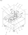
- Fig. 6 is a schematic perspective view of the application device 51 according to Example.
- the application device 51 according to Example of the present invention is mainly constituted by the above-described discharge device 1, an XYZ drive mechanism 52 that moves the workpiece 56, i.e., a target to which the liquid material 14 is discharged, and the above-described discharge device 1 relatively to each other, a conveying mechanism 53 that carries in the workpiece 56 from the outside of the application device 51, moves the workpiece 56 to an application work position, and that carries out the workpiece 56 to the outside of the application device 51, a stage 55 that fixedly supports the workpiece 56 during the application work, and an application control device 57 that controls operations of the above-mentioned devices and components.
- the discharge device 1 is installed on the XYZ drive mechanism 52 and is able to move, relative to the workpiece 56, in each of directions (i.e., an X moving direction 60, a Y moving direction 61, and a Z moving direction 62) denoted by individual arrows. While, in this Example, the discharge device 1 is constituted to be movable in the XYZ directions, the present invention is not limited to such a case. It is just needed that the discharge device 1 and the workpiece 56 can be moved relatively to each other. In another example, the discharge device 1 may be constituted to be movable only in the Z direction, and the stage 55 may be constituted to be movable in the XY directions. For example, a combination of a servo motor or a stepping motor and a ball screw, or a linear motor can be used as the XYZ drive mechanism 52.
- the application device 51 of this Example includes the conveying mechanism 53 for transferring the workpiece to and from not-illustrated devices in preceding and succeeding steps or loader/unloader.
- the conveying mechanism 53 has a structure in which two rail-like members 54 are installed parallel to each other in substantially the same width as that of the workpiece 56 to be conveyed, and not-illustrated belts are disposed on the rail-like members 54 to circulate with the aid of not-illustrated rollers.
- the rollers are rotated by a motor, for example, the belt is circulated and the workpiece 56 placed on the belt is conveyed in a direction (i.e., a carrying-in direction 63 or a carrying-out direction 64) denoted by an arrow.
- ends of the rail-like members 54 as viewed along a direction opposite to the carrying-in direction 63 constitute a carrying-in zone
- ends of the rail-like members 54 as viewed along the same direction as the carrying-in direction 63 constitute a carrying-out zone.
- a robot having an arm may be used, as the conveying mechanism 53, to transfer a substrate.
- the stage 55 is disposed between the two rail-like members 54 of the conveying mechanism 53.
- the stage 55 takes an elevated position where it fixedly supports the workpiece 56 while elevating the workpiece 56 stopped at a working position from below, and a lowered position where it is located away from the workpiece 56 not to interfere with the workpiece 56 when the workpiece 56 is transferred.
- a combination of a motor and a ball screw, or an air cylinder can be used as a device for elevating and lowering the stage 55.
- the workpiece 56 can be fixed onto the stage 55 by a method of attracting the workpiece 56 to be fixedly kept in place by boring a plurality of holes extending from the inside of the stage 55 to an upper surface thereof, and sucking air through the holes, a method of fixing the workpiece 56 by holding the workpiece 56 between fixing members, and fixating those members to the stage 55 with fixation means such as screws, or a method of fixedly sandwiching the workpiece 56 between a not-illustrated retainer included in the conveying mechanism 53 and the stage 55 at the elevated position of the stage 55.
- the XYZ drive mechanism 52, the conveying mechanism 53, and the stage 55 are disposed on a bench 58, and their surroundings are covered with a cover 59 denoted by dotted lines. Covering with the cover 59 prevents intrusion of dust from the outside and secures safety of workers. Though not illustrated, however, openings through which the workpiece 56 is carried in and out are formed at positions corresponding to the carrying-in side and the carrying-out side of the conveying mechanism 53.
- the discharge control device 10 may be installed inside the bench 58 though not illustrated in Fig. 6 .
- the application control device 57 for controlling the operations of the above-described devices and components includes a processor and a memory in which an application control program is stored. As denoted by dotted lines, the application control device 57 is installed inside the bench 58. Application pattern data necessary for performing the application work is stored in the memory of the application control device 57. The application control device 57 performs the above-described stirring work at the predetermined timing in cooperation with the discharge control device 10.
- the cooperation between the application control device 57 and the discharge control device 10 is made in such a manner that the discharge control device 10 controls the operations of the devices and components, which are required for the operations of the discharge device 1 to perform the discharge work and the stirring work, and that the application control device 57 instructs, for example, the timings of performing the discharge work and the stirring work, to the discharge control device 10.
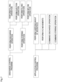
- Fig. 7 is a block diagram illustrating individual modules of a discharge control program and an application control program according to Example.
- the application control program sends a stirring operation command to the discharge control program at the following timings, for example:
- a timer for detecting the lapse of the certain time may be equipped in the application control device 57, and the program may be designed to perform the stirring operation once or multiple times when the timer detects the lapse of the certain time (the timer being implemented using hardware or software).
- the workpiece 56 is carried into the cover 59 of the application device 51 by the conveying mechanism 53 that conveys the workpiece 56 in a first direction.
- the workpiece 56 having been carried into the cover 59 is continuously conveyed in the first direction and is stopped upon arriving at the position (working position) where the stage 55 is installed.
- the stage 55 is elevated to fixedly support the workpiece 56.
- desired application work is performed by continuously discharging the liquid material 14 onto the workpiece 56 in accordance with a preset application pattern while the discharge device 1 is moved relative to the workpiece 56 by the XYZ drive mechanism 52.
- the wording "application pattern" used here includes, for example, the case of filling the liquid material into a region defined by dam in a state that the discharge port is stopped at a predetermined position after being moved there.
- the discharge device 1 finishes the application work on the workpiece 56
- the workpiece 56 is released from the fixed state, moved to the carrying-out side by the conveying mechanism 53, and then carried out to the outside of the cover 59 of the application device 51.
- the foregoing is a basic flow of the application work performed on one workpiece 56.
- programming is made to repeat the above-mentioned series of works (carrying-in of the workpiece, application, and carrying-out of the workpiece).
- the application control program is designed to perform the stirring operation by utilizing that timing at which the discharge operation is not performed (or rather cannot be performed). For example, the period of carrying in the workpiece 56 is immediately before the application operation (discharge operation). Therefore, by designing the program to perform the stirring operation in the period of carrying in the workpiece 56, the liquid material can be discharged in a state of the solid particles being dispersed in the liquid material, and a maximum effect is obtained.
- the timing to perform the stirring operation is not missed by designing the program to perform the stirring operation in the period of carrying in the workpiece 56.
- the program may be designed to perform the stirring operation in the period of carrying out the workpiece 56.
- the stirring operation may be performed in a period between carrying-out of one workpiece 56 and carrying-in of the next workpiece 56.
- the program may be designed to perform the stirring operation in a period in which the workpiece 56 is not carried in, such as a standby period.
- the application work can be always performed in the state of the solid particles being dispersed in the liquid, by sending the command for the stirring operation to the discharge control device 10 in accordance with the application control program in the period of carrying in or out the workpiece 56.
- discharge device 2 storage container (syringe), 3: measuring unit, 4: plunger, 5: nozzle, 6: selector valve, 7: plunger drive device, 8: selector valve drive device, 9: compressed gas source, 10: discharge control device, 11: tubing, 12: control wiring, 13: connection member, 14: liquid material, 15: base plate, 16: fixing member, 17: coupling portion, 18: slide rail, 19: valve block, 20: first flow passage, 21: second flow passage, 22: third flow passage, 23: valve element, 24: groove, 25: through-hole, 31: measuring hole, 51: application device, 52: XYZ drive mechanism, 53: conveying mechanism, 54: rail-like member, 55: stage, 56: workpiece, 57: application control device, 58: bench, 59: cover, 60: X moving direction, 61: Y moving direction, 62: Z moving direction, 63: carrying-in direction, 64: carrying-out direction, 131: connection flow passage, 132: connection portion
Landscapes
- Life Sciences & Earth Sciences (AREA)
- Engineering & Computer Science (AREA)
- Wood Science & Technology (AREA)
- Chemical & Material Sciences (AREA)
- Chemical Kinetics & Catalysis (AREA)
- Materials Engineering (AREA)
- Organic Chemistry (AREA)
- Coating Apparatus (AREA)
- Application Of Or Painting With Fluid Materials (AREA)
- Led Device Packages (AREA)
- Nozzles (AREA)
Claims (12)
- Abgabevorrichtung (1) für ein flüssiges Material (14), das feste Partikel enthält, wobei die Abgabevorrichtung (1) Folgendes aufweist:einen Speicherbehälter (2), in dem das flüssige Material (14), das feste Partikel enthält, gespeichert wird;eine Messeinheit (3), die ein Messloch (31) hat, in das das flüssige Material (14) gefüllt wird;einen Stößel (4), der in dem Messloch (31) vorwärts und rückwärts bewegt wird;eine Düse (5), die eine Abgabeöffnung hat, durch die das flüssige Material (14) abgegeben wird;ein Schaltventil (6), das eine erste Position, bei der der Speicherbehälter (2) und die Messeinheit (3) miteinander verbunden sind, und eine zweite Position hat, bei der die Messeinheit (3) und die Düse (5) miteinander verbunden sind;eine Stößel-Antriebsvorrichtung (7), die den Stößel (4) vorwärts und rückwärts bewegt;eine Schaltventil-Antriebsvorrichtung (8), die die erste Position und die zweite Position des Schaltventils (6) umschaltet; undeine Abgabe-Steuerungsvorrichtung (10), die einen Prozessor und einen Speicher aufweist, in dem ein Abgabe-Steuerungsprogramm gespeichert ist,wobei das Abgabe-Steuerungsprogramm Folgendes aufweist:einen Füllschritt des Betätigens des Schaltventils (6) zu der ersten Position, des Bewegens des Stößels (4) rückwärts, und des Füllens des flüssigen Materials (14) in das Messloch (31);einen Ausstoßschritt des Betätigens des Schaltventils (6) zu der zweiten Position, des Bewegens des Stößels (4) vorwärts und des Abgebens des flüssigen Materials (14) in dem Messloch (31) aus der Abgabeöffnung;einen Einfließschritt des Betätigens des Schaltventils (6) zu der ersten Position, des Bewegens des Stößels (4) vorwärts und des Veranlassens des flüssigen Materials (14) in dem Messloch (31), in den Speicherbehälter (2) zu fließen;einen Abgabeschritt des aufeinanderfolgenden Ausführens des Füllschritts und des Ausstoßschritts; undeinen Rührschritt des aufeinanderfolgenden Ausführens des Füllschritts und des Einfließschritts, dadurch gekennzeichnet, dassdie Abgabevorrichtung (1) ferner eine Druckgasquelle (9) aufweist, die konfiguriert ist, dem Speicherbehälter (2) durch eine Rohrleitung (11) ein Druckgas unter einem Druck zuzuführen, der durch die Abgabe-Steuerungsvorrichtung (10) eingestellt wird,dass dem Speicherbehälter (2) während des Füllschritts Druckgas unter einem Druck zugeführt wird, der durch die Abgabe-Steuerungsvorrichtung (10) eingestellt wird, unddass dem Speicherbehälter (2) während des Einfließschritts kein Druckgas zugeführt wird.
- Abgabevorrichtung (1) für das flüssige Material (14), das feste Partikel enthält, nach Anspruch 1, wobei das Abgabe-Steuerungsprogramm einen kontinuierlichen Rührschritt des kontinuierlichen Ausführens des Rührschritts aufweist.
- Abgabevorrichtung (1) für das flüssige Material (14), das feste Partikel enthält, nach Anspruch 1 oder 2, ferner mit einem Verbindungselement (13), das einen Verbindungsfließdurchgang (131) aufweist, der den Speicherbehälter (2) und die Messeinheit (3) miteinander in Verbindung bringt,
wobei eine Querschnittsfläche eines Verbindungsabschnitts (132) zwischen dem Verbindungsfließdurchgang (131) und dem Speicherbehälter (2) 1/4 oder weniger einer Querschnittsfläche des Speicherbehälters (2) beträgt. - Abgabevorrichtung (1) für das flüssige Material (14), das feste Partikel enthält, nach Anspruch 3, wobei die Querschnittsfläche des Verbindungsabschnitts (132) zwischen dem Verbindungsfließdurchgang (131) und dem Speicherbehälter (2) 1/10 oder weniger der Querschnittsfläche des Speicherbehälters (2) beträgt.
- Abgabevorrichtung (1) für das flüssige Material (14), das feste Partikel enthält, nach Anspruch 3 oder 4, wobei der Verbindungsfließdurchgang (131) aus einem linearen Fließdurchgang ausgebildet ist, der von einem Ende zu dem anderen Ende im Wesentlichen den gleichen Durchmesser hat.
- Auftragsvorrichtung (51) mit:der Abgabevorrichtung (1) für das flüssige Material (14), das feste Partikel enthält, nach einem der Ansprüche 1 bis 5;einem Tisch (55), an dem ein Werkstück (56) fixiert ist;einem XYZ-Antriebsmechanismus (52), der den Tisch (55) und die Abgabevorrichtung (1) relativ zueinander bewegt; undeiner Auftrag-Steuerungsvorrichtung (57), die einen Prozessor und einen Speicher aufweist, in dem ein Auftrag-Steuerungsprogramm gespeichert ist,wobei das Auftrag-Steuerungsprogramm Folgendes aufweist:
einen Auftragsschritt des Veranlassens der Abgabevorrichtung (1), den Abgabeschritt und den Rührschritt auszuführen, während der Tisch (55) und die Abgabevorrichtung (1) durch den XYZ-Antriebsmechanismus (52) in Übereinstimmung mit einem Auftragsmuster relativ zueinander bewegt werden. - Auftragsvorrichtung (51) nach Anspruch 6, ferner mit einem Fördermechanismus (53), der das Werkstück (56), das von einer Einbringungszone empfangen wird, zu dem Tisch (55) fördert und das Werkstück (56) von dem Tisch (55) zu einer Ausbringungszone fördert,
wobei das Auftrag-Steuerungsprogramm einen förderinternen Rührschritt des Veranlassens der Abgabe-Steuerungsvorrichtung (10), den Rührschritt einmal oder mehrmals auszuführen, während das Werkstück (56) durch den Fördermechanismus (53) gefördert wird, aufweist. - Auftragsvorrichtung (51) nach Anspruch 6 oder 7, wobei die Auftrag-Steuerungsvorrichtung (57) einen Zeitgeber aufweist, der ein Verstreichen einer gewissen Zeit von einem letzten Rührvorgang oder Abgabevorgang erfasst, und
das Auftrag-Steuerungsprogramm einen zeitvorgabefixierten Rührschritt des Veranlassens der Abgabe-Steuerungsvorrichtung (10), den Rührschritt einmal oder mehrmals unter der Bedingung auszuführen, dass der Zeitgeber das Verstreichen der gewissen Zeit erfasst und dass es eine Zeit gibt, bis zum Start des nächsten Abgabeschritts den Rührschritt auszuführen, aufweist. - Auftragsvorrichtung (51) nach einem der Ansprüche 6 bis 8, wobei das Auftrag-Steuerungsprogramm einen periodischen Rührschritt des periodischen Erfassens eines Zeitpunkts, bei dem es eine Zeit gibt, bis zum Start des nächsten Abgabeschritts den Rührschritt auszuführen, und des Veranlassens der Abgabe-Steuerungsvorrichtung (10), den Rührschritt einmal oder mehrmals bei dem erfassten Zeitpunkt durchzuführen, aufweist.
- Auftragsverfahren, das die Auftragsvorrichtung (51) nach einem der Ansprüche 6 bis 9 verwendet, wobei ein Auftragsmuster auf dem Werkstück (56) mit der Auftrag-Steuerungsvorrichtung (57) ausgebildet wird, die das Auftrag-Steuerungsprogramm ausführt.
- Auftragsverfahren nach Anspruch 10, wobei die festen Partikel feste Partikel aufweisen, die ein höheres spezifisches Gewicht haben als das flüssige Material (14).
- Auftragsverfahren nach Anspruch 11, wobei die festen Teilchen LED-Leuchtstoffe sind.
Priority Applications (1)
| Application Number | Priority Date | Filing Date | Title |
|---|---|---|---|
| RS20241266A RS66168B1 (sr) | 2015-07-24 | 2016-07-21 | Uređaj za pražnjenje i način pražnjenja tečnog materijala koji sadrži čvrste čestice |
Applications Claiming Priority (2)
| Application Number | Priority Date | Filing Date | Title |
|---|---|---|---|
| JP2015146472A JP6538465B2 (ja) | 2015-07-24 | 2015-07-24 | 固体粒子を含有する液体材料の吐出装置および塗布装置並びに塗布方法 |
| PCT/JP2016/071342 WO2017018304A1 (ja) | 2015-07-24 | 2016-07-21 | 固体粒子を含有する液体材料の吐出装置および吐出方法並びに塗布装置 |
Publications (3)
| Publication Number | Publication Date |
|---|---|
| EP3326723A1 EP3326723A1 (de) | 2018-05-30 |
| EP3326723A4 EP3326723A4 (de) | 2019-08-14 |
| EP3326723B1 true EP3326723B1 (de) | 2024-09-04 |
Family
ID=57886908
Family Applications (1)
| Application Number | Title | Priority Date | Filing Date |
|---|---|---|---|
| EP16830409.5A Active EP3326723B1 (de) | 2015-07-24 | 2016-07-21 | Entladungsvorrichtung und entladungsverfahren für flüssigmaterial mit feststoffpartikeln |
Country Status (15)
| Country | Link |
|---|---|
| US (1) | US10799906B2 (de) |
| EP (1) | EP3326723B1 (de) |
| JP (1) | JP6538465B2 (de) |
| KR (1) | KR102494077B1 (de) |
| CN (2) | CN119237244A (de) |
| HK (1) | HK1246245A1 (de) |
| HU (1) | HUE069257T2 (de) |
| MY (1) | MY192610A (de) |
| PH (1) | PH12018550004A1 (de) |
| PL (1) | PL3326723T3 (de) |
| RS (1) | RS66168B1 (de) |
| RU (1) | RU2706311C2 (de) |
| SG (1) | SG11201800033QA (de) |
| TW (1) | TWI717372B (de) |
| WO (1) | WO2017018304A1 (de) |
Families Citing this family (12)
| Publication number | Priority date | Publication date | Assignee | Title |
|---|---|---|---|---|
| JP6626364B2 (ja) * | 2016-02-24 | 2019-12-25 | 武蔵エンジニアリング株式会社 | 固体粒子を含有する液体材料の吐出装置および吐出方法並びに塗布装置 |
| JP6778426B2 (ja) * | 2016-09-20 | 2020-11-04 | 武蔵エンジニアリング株式会社 | 液体材料吐出装置 |
| CN109285937B (zh) * | 2018-08-16 | 2020-03-20 | 佛山市国星光电股份有限公司 | Led白光器件及其制备方法、led背光模组 |
| US11581547B2 (en) * | 2019-05-29 | 2023-02-14 | Uchicago Argonne, Llc | Electrode ink deposition system for high-throughput polymer electrolyte fuel cell |
| CN110646346A (zh) * | 2019-10-11 | 2020-01-03 | 宁波江丰生物信息技术有限公司 | 一种加油装置 |
| MX2022011288A (es) * | 2020-03-11 | 2022-10-07 | Musashi Eng Inc | Metodo de formacion de pelicula liquida plana y aparato de formacion de pelicula liquida plana. |
| US20210301943A1 (en) * | 2020-03-27 | 2021-09-30 | Illinois Tool Works Inc. | Dispensing unit having fixed flexible diaphragm seal |
| US11246249B2 (en) | 2020-04-15 | 2022-02-08 | Illinois Tool Works Inc. | Tilt and rotate dispenser having strain wave gear system |
| KR102367805B1 (ko) * | 2020-09-15 | 2022-02-25 | (주)에스티아이 | 디스플레이 제조를 위한 초소형 led 프린팅 장치 |
| US11904337B2 (en) | 2021-08-03 | 2024-02-20 | Illinois Tool Works Inc. | Tilt and rotate dispenser having material flow rate control |
| US11805634B2 (en) * | 2021-08-03 | 2023-10-31 | Illinois Tool Works Inc. | Tilt and rotate dispenser having motion control |
| JP7828547B2 (ja) * | 2022-03-02 | 2026-03-12 | 株式会社リコー | 液体吐出ヘッド、ヘッドユニット、液体吐出装置 |
Citations (2)
| Publication number | Priority date | Publication date | Assignee | Title |
|---|---|---|---|---|
| US3712591A (en) * | 1971-11-24 | 1973-01-23 | Nasa | Zero gravity liquid mixer |
| JPH0880464A (ja) * | 1994-09-14 | 1996-03-26 | Musashi Eng Co Ltd | フィラー入り液体材料の吐出装置 |
Family Cites Families (20)
| Publication number | Priority date | Publication date | Assignee | Title |
|---|---|---|---|---|
| US3122272A (en) * | 1960-08-04 | 1964-02-25 | Marsh Lyle | Fluid dispenser |
| US4027785A (en) * | 1976-04-12 | 1977-06-07 | Chicago Commutator, Inc. | Dual pump colorant dispenser |
| US6164499A (en) * | 1999-07-27 | 2000-12-26 | H.E.R.O. Industries A Division Of Middlefield Bancorp Limited | Paint colorant dispenser and valve therefor |
| JP4108353B2 (ja) | 2002-03-29 | 2008-06-25 | ノードソン コーポレーション | 液体吐出方法及び装置 |
| US6811058B2 (en) * | 2002-04-01 | 2004-11-02 | Fluid Management, Inc. | Valve assembly |
| KR101317734B1 (ko) | 2005-10-21 | 2013-10-15 | 무사시 엔지니어링 가부시키가이샤 | 액재 토출 장치 |
| JP5293179B2 (ja) * | 2006-02-23 | 2013-09-18 | コニカミノルタ株式会社 | 液体塗布装置 |
| JP2010108616A (ja) * | 2008-10-28 | 2010-05-13 | Panasonic Corp | プラズマディスプレイパネルの製造方法およびインクジェット装置 |
| JP5419616B2 (ja) * | 2009-09-25 | 2014-02-19 | 武蔵エンジニアリング株式会社 | 気泡混入防止機構および該機構を備える液体材料吐出装置並びに液体材料吐出方法 |
| JP2012066386A (ja) * | 2010-09-21 | 2012-04-05 | Panasonic Corp | 充填装置 |
| JP5779353B2 (ja) * | 2011-01-19 | 2015-09-16 | 武蔵エンジニアリング株式会社 | 液体材料の塗布方法、塗布装置およびプログラム |
| US20140323993A1 (en) * | 2011-03-25 | 2014-10-30 | Leo Pharma A/S | Applicator |
| US9724658B2 (en) * | 2011-03-28 | 2017-08-08 | Fast & Fluid Management B.V. | Method of homogenizing a liquid |
| ITTO20110125U1 (it) * | 2011-11-21 | 2013-05-22 | Stardale Ltd | Apparecchiatura per il dosaggio di liquidi |
| WO2013076849A1 (ja) * | 2011-11-24 | 2013-05-30 | フォイト パテント ゲゼルシャフト ミット ベシュレンクテル ハフツング | コータ用ヘッド |
| JP2013182967A (ja) * | 2012-03-01 | 2013-09-12 | Panasonic Corp | 樹脂塗布方法および樹脂塗布装置 |
| JP6006509B2 (ja) * | 2012-03-08 | 2016-10-12 | 武蔵エンジニアリング株式会社 | 液体定量吐出装置および塗布装置 |
| EP2781257B1 (de) * | 2013-03-18 | 2016-03-16 | Collomix Rühr-und Mischgeräte GmbH | Kanister für pumpfähige Medien, insbesondere für Farbpigmentpräparationen |
| JP6237181B2 (ja) * | 2013-12-06 | 2017-11-29 | 日亜化学工業株式会社 | 発光装置の製造方法 |
| JP6626364B2 (ja) * | 2016-02-24 | 2019-12-25 | 武蔵エンジニアリング株式会社 | 固体粒子を含有する液体材料の吐出装置および吐出方法並びに塗布装置 |
-
2015
- 2015-07-24 JP JP2015146472A patent/JP6538465B2/ja active Active
-
2016
- 2016-07-21 CN CN202411691497.6A patent/CN119237244A/zh active Pending
- 2016-07-21 US US15/746,108 patent/US10799906B2/en active Active
- 2016-07-21 MY MYPI2018700172A patent/MY192610A/en unknown
- 2016-07-21 HU HUE16830409A patent/HUE069257T2/hu unknown
- 2016-07-21 EP EP16830409.5A patent/EP3326723B1/de active Active
- 2016-07-21 KR KR1020187001549A patent/KR102494077B1/ko active Active
- 2016-07-21 RS RS20241266A patent/RS66168B1/sr unknown
- 2016-07-21 HK HK18105932.0A patent/HK1246245A1/zh unknown
- 2016-07-21 WO PCT/JP2016/071342 patent/WO2017018304A1/ja not_active Ceased
- 2016-07-21 PL PL16830409.5T patent/PL3326723T3/pl unknown
- 2016-07-21 SG SG11201800033QA patent/SG11201800033QA/en unknown
- 2016-07-21 CN CN201680043583.3A patent/CN107847962A/zh active Pending
- 2016-07-21 RU RU2018105697A patent/RU2706311C2/ru active
- 2016-07-22 TW TW105123228A patent/TWI717372B/zh active
-
2018
- 2018-01-23 PH PH12018550004A patent/PH12018550004A1/en unknown
Patent Citations (2)
| Publication number | Priority date | Publication date | Assignee | Title |
|---|---|---|---|---|
| US3712591A (en) * | 1971-11-24 | 1973-01-23 | Nasa | Zero gravity liquid mixer |
| JPH0880464A (ja) * | 1994-09-14 | 1996-03-26 | Musashi Eng Co Ltd | フィラー入り液体材料の吐出装置 |
Also Published As
| Publication number | Publication date |
|---|---|
| US20180214903A1 (en) | 2018-08-02 |
| KR102494077B1 (ko) | 2023-01-30 |
| PL3326723T3 (pl) | 2024-11-25 |
| HK1246245A1 (zh) | 2018-09-07 |
| RU2706311C2 (ru) | 2019-11-15 |
| CN119237244A (zh) | 2025-01-03 |
| SG11201800033QA (en) | 2018-02-27 |
| RS66168B1 (sr) | 2024-12-31 |
| MY192610A (en) | 2022-08-29 |
| JP2017023958A (ja) | 2017-02-02 |
| CN107847962A (zh) | 2018-03-27 |
| RU2018105697A3 (de) | 2019-10-09 |
| EP3326723A4 (de) | 2019-08-14 |
| JP6538465B2 (ja) | 2019-07-03 |
| PH12018550004A1 (en) | 2018-07-09 |
| EP3326723A1 (de) | 2018-05-30 |
| TW201724562A (zh) | 2017-07-01 |
| RU2018105697A (ru) | 2019-08-27 |
| HUE069257T2 (hu) | 2025-02-28 |
| KR20180032564A (ko) | 2018-03-30 |
| TWI717372B (zh) | 2021-02-01 |
| WO2017018304A1 (ja) | 2017-02-02 |
| US10799906B2 (en) | 2020-10-13 |
Similar Documents
| Publication | Publication Date | Title |
|---|---|---|
| EP3326723B1 (de) | Entladungsvorrichtung und entladungsverfahren für flüssigmaterial mit feststoffpartikeln | |
| US11266957B2 (en) | Discharge device for liquid material containing solid particles, discharge method and coating device | |
| CN104169009B (zh) | 液体材料吐出机构及液体材料吐出装置 | |
| TW201518630A (zh) | 多點密封件潤滑系統 | |
| KR20100116666A (ko) | 액체 재료의 토출 장치, 및 그 도포 장치 및 도포 방법 | |
| KR20100088694A (ko) | 페이스트 도포장치 | |
| CN106687223A (zh) | 用于分配器的阀座 | |
| HK40114265A (zh) | 含有固体颗粒的液体材料的涂布装置及涂布方法 | |
| HK40049188A (en) | Discharge device for liquid material containing solid particles, discharge method, and coating device | |
| KR102942211B1 (ko) | 롤투롤 멀티 코팅 장치 | |
| HK1261093A1 (en) | Discharge device for liquid material containing solid particles, discharge method, and coating device | |
| HK1261093B (en) | Discharge device for liquid material containing solid particles, discharge method, and coating device | |
| CN116899776A (zh) | 喷射设备及其工作方法 | |
| KR101484286B1 (ko) | 슬롯 다이 코팅 장치 | |
| JP2014042898A (ja) | ダイヘッド |
Legal Events
| Date | Code | Title | Description |
|---|---|---|---|
| STAA | Information on the status of an ep patent application or granted ep patent |
Free format text: STATUS: THE INTERNATIONAL PUBLICATION HAS BEEN MADE |
|
| PUAI | Public reference made under article 153(3) epc to a published international application that has entered the european phase |
Free format text: ORIGINAL CODE: 0009012 |
|
| STAA | Information on the status of an ep patent application or granted ep patent |
Free format text: STATUS: REQUEST FOR EXAMINATION WAS MADE |
|
| 17P | Request for examination filed |
Effective date: 20180110 |
|
| AK | Designated contracting states |
Kind code of ref document: A1 Designated state(s): AL AT BE BG CH CY CZ DE DK EE ES FI FR GB GR HR HU IE IS IT LI LT LU LV MC MK MT NL NO PL PT RO RS SE SI SK SM TR |
|
| AX | Request for extension of the european patent |
Extension state: BA ME |
|
| DAV | Request for validation of the european patent (deleted) | ||
| DAX | Request for extension of the european patent (deleted) | ||
| RIC1 | Information provided on ipc code assigned before grant |
Ipc: B05C 5/02 20060101ALI20190218BHEP Ipc: B01F 11/00 20060101AFI20190218BHEP |
|
| A4 | Supplementary search report drawn up and despatched |
Effective date: 20190711 |
|
| RIC1 | Information provided on ipc code assigned before grant |
Ipc: B01F 11/00 20060101AFI20190705BHEP Ipc: B05C 5/02 20060101ALI20190705BHEP Ipc: B05C 11/10 20060101ALI20190705BHEP Ipc: B05C 17/005 20060101ALN20190705BHEP |
|
| STAA | Information on the status of an ep patent application or granted ep patent |
Free format text: STATUS: EXAMINATION IS IN PROGRESS |
|
| 17Q | First examination report despatched |
Effective date: 20210202 |
|
| REG | Reference to a national code |
Ref country code: DE Ref legal event code: R079 Free format text: PREVIOUS MAIN CLASS: B05C0005000000 Ipc: B01F0031650000 Ref country code: DE Ref legal event code: R079 Ref document number: 602016089270 Country of ref document: DE Free format text: PREVIOUS MAIN CLASS: B05C0005000000 Ipc: B01F0031650000 |
|
| GRAP | Despatch of communication of intention to grant a patent |
Free format text: ORIGINAL CODE: EPIDOSNIGR1 |
|
| STAA | Information on the status of an ep patent application or granted ep patent |
Free format text: STATUS: GRANT OF PATENT IS INTENDED |
|
| RIC1 | Information provided on ipc code assigned before grant |
Ipc: B05C 17/005 20060101ALN20240221BHEP Ipc: B05C 11/10 20060101ALI20240221BHEP Ipc: B05C 5/02 20060101ALI20240221BHEP Ipc: B01F 31/65 20220101AFI20240221BHEP |
|
| INTG | Intention to grant announced |
Effective date: 20240320 |
|
| GRAS | Grant fee paid |
Free format text: ORIGINAL CODE: EPIDOSNIGR3 |
|
| GRAA | (expected) grant |
Free format text: ORIGINAL CODE: 0009210 |
|
| STAA | Information on the status of an ep patent application or granted ep patent |
Free format text: STATUS: THE PATENT HAS BEEN GRANTED |
|
| P01 | Opt-out of the competence of the unified patent court (upc) registered |
Free format text: CASE NUMBER: APP_42871/2024 Effective date: 20240722 |
|
| AK | Designated contracting states |
Kind code of ref document: B1 Designated state(s): AL AT BE BG CH CY CZ DE DK EE ES FI FR GB GR HR HU IE IS IT LI LT LU LV MC MK MT NL NO PL PT RO RS SE SI SK SM TR |
|
| REG | Reference to a national code |
Ref country code: GB Ref legal event code: FG4D |
|
| REG | Reference to a national code |
Ref country code: CH Ref legal event code: EP |
|
| REG | Reference to a national code |
Ref country code: IE Ref legal event code: FG4D |
|
| REG | Reference to a national code |
Ref country code: DE Ref legal event code: R096 Ref document number: 602016089270 Country of ref document: DE |
|
| REG | Reference to a national code |
Ref country code: SE Ref legal event code: TRGR |
|
| REG | Reference to a national code |
Ref country code: LT Ref legal event code: MG9D |
|
| REG | Reference to a national code |
Ref country code: NL Ref legal event code: MP Effective date: 20240904 |
|
| PG25 | Lapsed in a contracting state [announced via postgrant information from national office to epo] |
Ref country code: NO Free format text: LAPSE BECAUSE OF FAILURE TO SUBMIT A TRANSLATION OF THE DESCRIPTION OR TO PAY THE FEE WITHIN THE PRESCRIBED TIME-LIMIT Effective date: 20241204 |
|
| PG25 | Lapsed in a contracting state [announced via postgrant information from national office to epo] |
Ref country code: GR Free format text: LAPSE BECAUSE OF FAILURE TO SUBMIT A TRANSLATION OF THE DESCRIPTION OR TO PAY THE FEE WITHIN THE PRESCRIBED TIME-LIMIT Effective date: 20241205 Ref country code: FI Free format text: LAPSE BECAUSE OF FAILURE TO SUBMIT A TRANSLATION OF THE DESCRIPTION OR TO PAY THE FEE WITHIN THE PRESCRIBED TIME-LIMIT Effective date: 20240904 |
|
| PG25 | Lapsed in a contracting state [announced via postgrant information from national office to epo] |
Ref country code: BG Free format text: LAPSE BECAUSE OF FAILURE TO SUBMIT A TRANSLATION OF THE DESCRIPTION OR TO PAY THE FEE WITHIN THE PRESCRIBED TIME-LIMIT Effective date: 20240904 |
|
| PG25 | Lapsed in a contracting state [announced via postgrant information from national office to epo] |
Ref country code: LV Free format text: LAPSE BECAUSE OF FAILURE TO SUBMIT A TRANSLATION OF THE DESCRIPTION OR TO PAY THE FEE WITHIN THE PRESCRIBED TIME-LIMIT Effective date: 20240904 |
|
| PG25 | Lapsed in a contracting state [announced via postgrant information from national office to epo] |
Ref country code: HR Free format text: LAPSE BECAUSE OF FAILURE TO SUBMIT A TRANSLATION OF THE DESCRIPTION OR TO PAY THE FEE WITHIN THE PRESCRIBED TIME-LIMIT Effective date: 20240904 |
|
| PG25 | Lapsed in a contracting state [announced via postgrant information from national office to epo] |
Ref country code: ES Free format text: LAPSE BECAUSE OF FAILURE TO SUBMIT A TRANSLATION OF THE DESCRIPTION OR TO PAY THE FEE WITHIN THE PRESCRIBED TIME-LIMIT Effective date: 20240904 |
|
| PG25 | Lapsed in a contracting state [announced via postgrant information from national office to epo] |
Ref country code: NO Free format text: LAPSE BECAUSE OF FAILURE TO SUBMIT A TRANSLATION OF THE DESCRIPTION OR TO PAY THE FEE WITHIN THE PRESCRIBED TIME-LIMIT Effective date: 20241204 Ref country code: LV Free format text: LAPSE BECAUSE OF FAILURE TO SUBMIT A TRANSLATION OF THE DESCRIPTION OR TO PAY THE FEE WITHIN THE PRESCRIBED TIME-LIMIT Effective date: 20240904 Ref country code: HR Free format text: LAPSE BECAUSE OF FAILURE TO SUBMIT A TRANSLATION OF THE DESCRIPTION OR TO PAY THE FEE WITHIN THE PRESCRIBED TIME-LIMIT Effective date: 20240904 Ref country code: GR Free format text: LAPSE BECAUSE OF FAILURE TO SUBMIT A TRANSLATION OF THE DESCRIPTION OR TO PAY THE FEE WITHIN THE PRESCRIBED TIME-LIMIT Effective date: 20241205 Ref country code: FI Free format text: LAPSE BECAUSE OF FAILURE TO SUBMIT A TRANSLATION OF THE DESCRIPTION OR TO PAY THE FEE WITHIN THE PRESCRIBED TIME-LIMIT Effective date: 20240904 Ref country code: ES Free format text: LAPSE BECAUSE OF FAILURE TO SUBMIT A TRANSLATION OF THE DESCRIPTION OR TO PAY THE FEE WITHIN THE PRESCRIBED TIME-LIMIT Effective date: 20240904 Ref country code: BG Free format text: LAPSE BECAUSE OF FAILURE TO SUBMIT A TRANSLATION OF THE DESCRIPTION OR TO PAY THE FEE WITHIN THE PRESCRIBED TIME-LIMIT Effective date: 20240904 |
|
| REG | Reference to a national code |
Ref country code: AT Ref legal event code: MK05 Ref document number: 1719779 Country of ref document: AT Kind code of ref document: T Effective date: 20240904 |
|
| PG25 | Lapsed in a contracting state [announced via postgrant information from national office to epo] |
Ref country code: NL Free format text: LAPSE BECAUSE OF FAILURE TO SUBMIT A TRANSLATION OF THE DESCRIPTION OR TO PAY THE FEE WITHIN THE PRESCRIBED TIME-LIMIT Effective date: 20240904 |
|
| REG | Reference to a national code |
Ref country code: HU Ref legal event code: AG4A Ref document number: E069257 Country of ref document: HU |
|
| PG25 | Lapsed in a contracting state [announced via postgrant information from national office to epo] |
Ref country code: PT Free format text: LAPSE BECAUSE OF FAILURE TO SUBMIT A TRANSLATION OF THE DESCRIPTION OR TO PAY THE FEE WITHIN THE PRESCRIBED TIME-LIMIT Effective date: 20250106 Ref country code: IS Free format text: LAPSE BECAUSE OF FAILURE TO SUBMIT A TRANSLATION OF THE DESCRIPTION OR TO PAY THE FEE WITHIN THE PRESCRIBED TIME-LIMIT Effective date: 20250104 |
|
| PG25 | Lapsed in a contracting state [announced via postgrant information from national office to epo] |
Ref country code: RO Free format text: LAPSE BECAUSE OF FAILURE TO SUBMIT A TRANSLATION OF THE DESCRIPTION OR TO PAY THE FEE WITHIN THE PRESCRIBED TIME-LIMIT Effective date: 20240904 Ref country code: SM Free format text: LAPSE BECAUSE OF FAILURE TO SUBMIT A TRANSLATION OF THE DESCRIPTION OR TO PAY THE FEE WITHIN THE PRESCRIBED TIME-LIMIT Effective date: 20240904 |
|
| PG25 | Lapsed in a contracting state [announced via postgrant information from national office to epo] |
Ref country code: EE Free format text: LAPSE BECAUSE OF FAILURE TO SUBMIT A TRANSLATION OF THE DESCRIPTION OR TO PAY THE FEE WITHIN THE PRESCRIBED TIME-LIMIT Effective date: 20240904 Ref country code: AT Free format text: LAPSE BECAUSE OF FAILURE TO SUBMIT A TRANSLATION OF THE DESCRIPTION OR TO PAY THE FEE WITHIN THE PRESCRIBED TIME-LIMIT Effective date: 20240904 |
|
| PG25 | Lapsed in a contracting state [announced via postgrant information from national office to epo] |
Ref country code: SK Free format text: LAPSE BECAUSE OF FAILURE TO SUBMIT A TRANSLATION OF THE DESCRIPTION OR TO PAY THE FEE WITHIN THE PRESCRIBED TIME-LIMIT Effective date: 20240904 |
|
| REG | Reference to a national code |
Ref country code: DE Ref legal event code: R097 Ref document number: 602016089270 Country of ref document: DE |
|
| PGFP | Annual fee paid to national office [announced via postgrant information from national office to epo] |
Ref country code: PL Payment date: 20250626 Year of fee payment: 10 |
|
| PG25 | Lapsed in a contracting state [announced via postgrant information from national office to epo] |
Ref country code: DK Free format text: LAPSE BECAUSE OF FAILURE TO SUBMIT A TRANSLATION OF THE DESCRIPTION OR TO PAY THE FEE WITHIN THE PRESCRIBED TIME-LIMIT Effective date: 20240904 |
|
| PLBE | No opposition filed within time limit |
Free format text: ORIGINAL CODE: 0009261 |
|
| STAA | Information on the status of an ep patent application or granted ep patent |
Free format text: STATUS: NO OPPOSITION FILED WITHIN TIME LIMIT |
|
| PGFP | Annual fee paid to national office [announced via postgrant information from national office to epo] |
Ref country code: HU Payment date: 20250723 Year of fee payment: 10 |
|
| 26N | No opposition filed |
Effective date: 20250605 |
|
| PGFP | Annual fee paid to national office [announced via postgrant information from national office to epo] |
Ref country code: DE Payment date: 20250722 Year of fee payment: 10 |
|
| PGFP | Annual fee paid to national office [announced via postgrant information from national office to epo] |
Ref country code: IT Payment date: 20250724 Year of fee payment: 10 |
|
| PGFP | Annual fee paid to national office [announced via postgrant information from national office to epo] |
Ref country code: GB Payment date: 20250722 Year of fee payment: 10 |
|
| PGFP | Annual fee paid to national office [announced via postgrant information from national office to epo] |
Ref country code: FR Payment date: 20250725 Year of fee payment: 10 |
|
| PGFP | Annual fee paid to national office [announced via postgrant information from national office to epo] |
Ref country code: CH Payment date: 20250801 Year of fee payment: 10 Ref country code: SE Payment date: 20250722 Year of fee payment: 10 |
|
| PGFP | Annual fee paid to national office [announced via postgrant information from national office to epo] |
Ref country code: RS Payment date: 20250711 Year of fee payment: 10 Ref country code: CZ Payment date: 20250715 Year of fee payment: 10 |
|
| PG25 | Lapsed in a contracting state [announced via postgrant information from national office to epo] |
Ref country code: LU Free format text: LAPSE BECAUSE OF NON-PAYMENT OF DUE FEES Effective date: 20250721 |
|
| REG | Reference to a national code |
Ref country code: BE Ref legal event code: MM Effective date: 20250731 |
|
| PG25 | Lapsed in a contracting state [announced via postgrant information from national office to epo] |
Ref country code: BE Free format text: LAPSE BECAUSE OF NON-PAYMENT OF DUE FEES Effective date: 20250731 |