WO2017018304A1 - 固体粒子を含有する液体材料の吐出装置および吐出方法並びに塗布装置 - Google Patents
固体粒子を含有する液体材料の吐出装置および吐出方法並びに塗布装置 Download PDFInfo
- Publication number
- WO2017018304A1 WO2017018304A1 PCT/JP2016/071342 JP2016071342W WO2017018304A1 WO 2017018304 A1 WO2017018304 A1 WO 2017018304A1 JP 2016071342 W JP2016071342 W JP 2016071342W WO 2017018304 A1 WO2017018304 A1 WO 2017018304A1
- Authority
- WO
- WIPO (PCT)
- Prior art keywords
- discharge
- liquid material
- solid particles
- storage container
- switching valve
- Prior art date
- Legal status (The legal status is an assumption and is not a legal conclusion. Google has not performed a legal analysis and makes no representation as to the accuracy of the status listed.)
- Ceased
Links
Images


Classifications
-
- B—PERFORMING OPERATIONS; TRANSPORTING
- B01—PHYSICAL OR CHEMICAL PROCESSES OR APPARATUS IN GENERAL
- B01F—MIXING, e.g. DISSOLVING, EMULSIFYING OR DISPERSING
- B01F31/00—Mixers with shaking, oscillating, or vibrating mechanisms
- B01F31/65—Mixers with shaking, oscillating, or vibrating mechanisms the materials to be mixed being directly submitted to a pulsating movement, e.g. by means of an oscillating piston or air column
- B01F31/651—Mixing by successively aspirating a part of the mixture in a conduit, e.g. a piston, and reinjecting it through the same conduit into the receptacle
-
- B—PERFORMING OPERATIONS; TRANSPORTING
- B05—SPRAYING OR ATOMISING IN GENERAL; APPLYING FLUENT MATERIALS TO SURFACES, IN GENERAL
- B05C—APPARATUS FOR APPLYING FLUENT MATERIALS TO SURFACES, IN GENERAL
- B05C11/00—Component parts, details or accessories not specifically provided for in groups B05C1/00 - B05C9/00
- B05C11/10—Storage, supply or control of liquid or other fluent material; Recovery of excess liquid or other fluent material
- B05C11/1002—Means for controlling supply, i.e. flow or pressure, of liquid or other fluent material to the applying apparatus, e.g. valves
- B05C11/1034—Means for controlling supply, i.e. flow or pressure, of liquid or other fluent material to the applying apparatus, e.g. valves specially designed for conducting intermittent application of small quantities, e.g. drops, of coating material
-
- B—PERFORMING OPERATIONS; TRANSPORTING
- B05—SPRAYING OR ATOMISING IN GENERAL; APPLYING FLUENT MATERIALS TO SURFACES, IN GENERAL
- B05C—APPARATUS FOR APPLYING FLUENT MATERIALS TO SURFACES, IN GENERAL
- B05C11/00—Component parts, details or accessories not specifically provided for in groups B05C1/00 - B05C9/00
- B05C11/11—Vats or other containers for liquids or other fluent materials
-
- B—PERFORMING OPERATIONS; TRANSPORTING
- B05—SPRAYING OR ATOMISING IN GENERAL; APPLYING FLUENT MATERIALS TO SURFACES, IN GENERAL
- B05C—APPARATUS FOR APPLYING FLUENT MATERIALS TO SURFACES, IN GENERAL
- B05C13/00—Means for manipulating or holding work, e.g. for separate articles
- B05C13/02—Means for manipulating or holding work, e.g. for separate articles for particular articles
-
- B—PERFORMING OPERATIONS; TRANSPORTING
- B05—SPRAYING OR ATOMISING IN GENERAL; APPLYING FLUENT MATERIALS TO SURFACES, IN GENERAL
- B05C—APPARATUS FOR APPLYING FLUENT MATERIALS TO SURFACES, IN GENERAL
- B05C5/00—Apparatus in which liquid or other fluent material is projected, poured or allowed to flow on to the surface of the work
- B05C5/02—Apparatus in which liquid or other fluent material is projected, poured or allowed to flow on to the surface of the work the liquid or other fluent material being discharged through an outlet orifice by pressure, e.g. from an outlet device in contact or almost in contact, with the work
- B05C5/0225—Apparatus in which liquid or other fluent material is projected, poured or allowed to flow on to the surface of the work the liquid or other fluent material being discharged through an outlet orifice by pressure, e.g. from an outlet device in contact or almost in contact, with the work characterised by flow controlling means, e.g. valves, located proximate the outlet
- B05C5/0229—Apparatus in which liquid or other fluent material is projected, poured or allowed to flow on to the surface of the work the liquid or other fluent material being discharged through an outlet orifice by pressure, e.g. from an outlet device in contact or almost in contact, with the work characterised by flow controlling means, e.g. valves, located proximate the outlet the valve being a gate valve or a sliding valve
- B05C5/0233—Apparatus in which liquid or other fluent material is projected, poured or allowed to flow on to the surface of the work the liquid or other fluent material being discharged through an outlet orifice by pressure, e.g. from an outlet device in contact or almost in contact, with the work characterised by flow controlling means, e.g. valves, located proximate the outlet the valve being a gate valve or a sliding valve rotating valve, e.g. rotating perforated cylinder
-
- B—PERFORMING OPERATIONS; TRANSPORTING
- B05—SPRAYING OR ATOMISING IN GENERAL; APPLYING FLUENT MATERIALS TO SURFACES, IN GENERAL
- B05D—PROCESSES FOR APPLYING FLUENT MATERIALS TO SURFACES, IN GENERAL
- B05D1/00—Processes for applying liquids or other fluent materials
- B05D1/26—Processes for applying liquids or other fluent materials performed by applying the liquid or other fluent material from an outlet device in contact with, or almost in contact with, the surface
-
- B—PERFORMING OPERATIONS; TRANSPORTING
- B05—SPRAYING OR ATOMISING IN GENERAL; APPLYING FLUENT MATERIALS TO SURFACES, IN GENERAL
- B05D—PROCESSES FOR APPLYING FLUENT MATERIALS TO SURFACES, IN GENERAL
- B05D7/00—Processes, other than flocking, specially adapted for applying liquids or other fluent materials to particular surfaces or for applying particular liquids or other fluent materials
- B05D7/24—Processes, other than flocking, specially adapted for applying liquids or other fluent materials to particular surfaces or for applying particular liquids or other fluent materials for applying particular liquids or other fluent materials
-
- C—CHEMISTRY; METALLURGY
- C09—DYES; PAINTS; POLISHES; NATURAL RESINS; ADHESIVES; COMPOSITIONS NOT OTHERWISE PROVIDED FOR; APPLICATIONS OF MATERIALS NOT OTHERWISE PROVIDED FOR
- C09D—COATING COMPOSITIONS, e.g. PAINTS, VARNISHES OR LACQUERS; FILLING PASTES; CHEMICAL PAINT OR INK REMOVERS; INKS; CORRECTING FLUIDS; WOODSTAINS; PASTES OR SOLIDS FOR COLOURING OR PRINTING; USE OF MATERIALS THEREFOR
- C09D5/00—Coating compositions, e.g. paints, varnishes or lacquers, characterised by their physical nature or the effects produced; Filling pastes
- C09D5/22—Luminous paints
-
- H—ELECTRICITY
- H10—SEMICONDUCTOR DEVICES; ELECTRIC SOLID-STATE DEVICES NOT OTHERWISE PROVIDED FOR
- H10H—INORGANIC LIGHT-EMITTING SEMICONDUCTOR DEVICES HAVING POTENTIAL BARRIERS
- H10H20/00—Individual inorganic light-emitting semiconductor devices having potential barriers, e.g. light-emitting diodes [LED]
- H10H20/80—Constructional details
- H10H20/85—Packages
- H10H20/851—Wavelength conversion means
-
- B—PERFORMING OPERATIONS; TRANSPORTING
- B05—SPRAYING OR ATOMISING IN GENERAL; APPLYING FLUENT MATERIALS TO SURFACES, IN GENERAL
- B05C—APPARATUS FOR APPLYING FLUENT MATERIALS TO SURFACES, IN GENERAL
- B05C17/00—Hand tools or apparatus using hand held tools, for applying liquids or other fluent materials to, for spreading applied liquids or other fluent materials on, or for partially removing applied liquids or other fluent materials from, surfaces
- B05C17/005—Hand tools or apparatus using hand held tools, for applying liquids or other fluent materials to, for spreading applied liquids or other fluent materials on, or for partially removing applied liquids or other fluent materials from, surfaces for discharging material from a reservoir or container located in or on the hand tool through an outlet orifice by pressure without using surface contacting members like pads or brushes
- B05C17/00573—Hand tools or apparatus using hand held tools, for applying liquids or other fluent materials to, for spreading applied liquids or other fluent materials on, or for partially removing applied liquids or other fluent materials from, surfaces for discharging material from a reservoir or container located in or on the hand tool through an outlet orifice by pressure without using surface contacting members like pads or brushes the reservoir or container being pneumatically or hydraulically pressurized
-
- B—PERFORMING OPERATIONS; TRANSPORTING
- B05—SPRAYING OR ATOMISING IN GENERAL; APPLYING FLUENT MATERIALS TO SURFACES, IN GENERAL
- B05C—APPARATUS FOR APPLYING FLUENT MATERIALS TO SURFACES, IN GENERAL
- B05C5/00—Apparatus in which liquid or other fluent material is projected, poured or allowed to flow on to the surface of the work
- B05C5/02—Apparatus in which liquid or other fluent material is projected, poured or allowed to flow on to the surface of the work the liquid or other fluent material being discharged through an outlet orifice by pressure, e.g. from an outlet device in contact or almost in contact, with the work
- B05C5/0208—Apparatus in which liquid or other fluent material is projected, poured or allowed to flow on to the surface of the work the liquid or other fluent material being discharged through an outlet orifice by pressure, e.g. from an outlet device in contact or almost in contact, with the work for applying liquid or other fluent material to separate articles
- B05C5/0212—Apparatus in which liquid or other fluent material is projected, poured or allowed to flow on to the surface of the work the liquid or other fluent material being discharged through an outlet orifice by pressure, e.g. from an outlet device in contact or almost in contact, with the work for applying liquid or other fluent material to separate articles only at particular parts of the articles
- B05C5/0216—Apparatus in which liquid or other fluent material is projected, poured or allowed to flow on to the surface of the work the liquid or other fluent material being discharged through an outlet orifice by pressure, e.g. from an outlet device in contact or almost in contact, with the work for applying liquid or other fluent material to separate articles only at particular parts of the articles by relative movement of article and outlet according to a predetermined path
Definitions
- the present invention relates to an apparatus and a method for applying a liquid material containing solid particles in a state where the solid particles are diffused.
- a “dispenser” that has a container for storing liquid material and discharges from the nozzle by a predetermined amount by the action of gas pressure or mechanical pressure from a nozzle connected to the container.
- the device is known.
- the nozzle disclosed in Patent Document 1 is filled with liquid material to be discharged by retreating a plunger slidingly contacting the inner wall of the measurement hole, and the nozzle is advanced by advancing the plunger.
- a dispenser that discharges the liquid material from.
- the stirring of the liquid is generally performed by providing a stirring device in the container.
- a stirring device in the container.
- sedimentation of solid particles or the like occurs in the middle of the pipe connecting the container and the discharge mechanism, and in many cases, the discharge cannot be performed in a state where the solid particles are diffused.
- the following methods and apparatuses have been proposed so far.
- Patent Document 2 applies a pressure of 0.001 MPa to 10 MPa to a liquid containing solid particles filled in at least one of two or more containers, while the liquid in the remaining at least one container
- a discharge passage having a substantially uniform inner diameter is provided at the lower end of a container for a liquid material containing filler, and a through passage is provided in the vicinity of the discharge port in the discharge passage.
- This is a discharge device for a liquid material containing filler, in which a valve having a rotary valve body is disposed and a reciprocating pump is connected to the discharge passage on the upstream side of the valve.
- the apparatus described in Patent Document 2 has a complicated equipment configuration, such as providing two containers and adjusting the flow rate between the two containers.
- the apparatus described in Patent Literature 3 requires a pump for stirring to be connected to the discharge flow path, and the equipment configuration is complicated. If a diffusion branching channel is provided in the channel through which the liquid material passes, stagnation of the flow occurs at the branching part, causing particle deposition.
- the present invention has an object of providing an apparatus and a method for discharging a liquid containing solid particles in a state in which the solid particles are diffused with a minimum additional configuration for diffusing the solid particles.
- the discharge device for a liquid material containing solid particles includes a storage container for storing the liquid material containing solid particles, a measuring portion having a measuring hole filled with the liquid material, and advancing and retreating in the measuring hole.
- a switching valve having a moving plunger, a nozzle having a discharge port for discharging the liquid material, a first position for communicating the storage container and the metering unit, and a second position for communicating the metering unit and the nozzle
- a plunger driving device that moves the plunger forward and backward, a switching valve driving device that switches the first position and the second position of the switching valve, and a discharge control device that includes a processor and a storage device that stores a discharge control program.
- the discharge control program sets the switching valve to the first position and moves the plunger backward to fill the liquid material into the metering hole.
- the liquid material in the measurement hole flows into the storage container by moving forward, the discharge step for continuously executing the filling step and the discharging step, the filling step and the inflow step And a stirring step for continuously executing.
- Said discharge apparatus WHEREIN The said discharge control program is good also as comprising the continuous stirring step which performs the said stirring step continuously.
- the discharge device further includes a connection member having a connection channel that communicates the storage container and the measuring unit, and a cross-sectional area of a connection part between the connection channel and the storage container is
- the cross-sectional area may be 1/4 or less, and in this case, preferably, the cross-sectional area of the connection portion between the connection flow path and the storage container is 1/10 or less of the cross-sectional area of the storage container.
- the connection flow path is composed of a linear flow path having substantially the same diameter from one end to the other end.
- a coating apparatus includes a discharge device for a liquid material containing the solid particles, a stage for fixing a workpiece, an XYZ drive mechanism for moving the stage and the discharge device relative to each other, a processor, and a coating control program.
- a coating control device including a stored storage device, wherein the coating control program moves the stage and the discharge device relative to each other by the XYZ drive mechanism based on a coating pattern, and discharges the discharge device to the discharge device.
- a coating step for executing the stirring step The coating apparatus further includes a transport mechanism that transports the workpiece received from the carry-in section to the stage and transports the workpiece from the stage to the unload section, and the coating control program transports the work by the transport mechanism.
- the coating control device includes a timer that detects that a fixed time has elapsed since the last stirring operation or discharging operation, and the coating control program detects the passage of the fixed time
- the discharge control device may include a regular agitation step for causing the agitation step to be executed once or more.
- the coating control program detects a timing at which the stirring step is performed at a constant cycle until the next discharging step is executed, and the stirring control unit performs the stirring step at the timing.
- a periodic stirring step that is executed once or more may be provided.
- the coating method of the present invention is a coating method using the above-described coating apparatus, wherein the coating control apparatus forms a coating pattern on a workpiece by executing the coating control program.
- the solid particles may include solid particles having a specific gravity greater than that of the liquid material.
- the solid particles may be LED phosphors.
- the present invention it is possible to discharge a liquid material containing solid particles in a state where the solid particles are diffused while minimizing an additional configuration for stirring. Further, since the agitation is performed by reversing the flow of the liquid material in the same flow path, the solid particle deposition in the flow path can be minimized.
- liquid material used in the present specification is a liquid material containing solid particles unless otherwise specified.
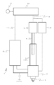
- a discharge device 1 includes a storage container 2 that stores a liquid material 14, a weighing unit 3 that is filled with the liquid material 14, and a weighing unit 3.
- a plunger 4 that moves forward and backward, a nozzle 5 having a discharge port for discharging the liquid material 14, a switching valve 6 that switches communication between the storage container 2 and the metering unit 3 or communication between the metering unit 3 and the nozzle 5;
- a plunger driving device 7 that moves the plunger 4 forward and backward, a switching valve driving device 8 that changes the direction of the switching valve 6, and a discharge control device 10 are configured.
- the storage container 2 communicates with the measuring unit 3 via the switching valve 6 and stores the liquid material supplied to the measuring unit 3.
- the discharge device 1 of a preferable form connects the compressed gas source 9 which supplies compressed gas, and supplies the compressed gas adjusted by the discharge control apparatus 10 to the storage container 2 via the piping 11.
- the measuring unit 3 is a cylindrical member having a measuring hole 31 that is a space in which a liquid material to be discharged from the nozzle 5 is temporarily stored.
- the measuring hole 31 is a cylindrical space, and a plunger 4 that is in sliding contact with the inner peripheral surface of the measuring unit 3 is inserted therein.
- the measuring unit 3 is fixed to a switching block constituting the switching valve 6.
- the plunger 4 is a rod-shaped member, and at least the outer peripheral surface of the tip portion is in sliding contact with the inner peripheral surface of the measuring hole 31.
- the plunger 4 is reciprocated by the plunger driving device 7.
- the nozzle 5 has a discharge flow path and a discharge port formed therein, and is fixed below the switching valve 6.
- the centers of the discharge port, the discharge flow path, and the measuring hole 31 are arranged on the same straight line.
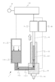
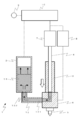
- the switching valve 6 has a first position (see FIG. 2) that communicates the storage container 2 and the measuring unit 3, and a second position (see FIG. 4) that communicates the measuring unit 3 and the nozzle 5.
- the first position and the second position are switched by the switching valve driving device 8 that has received a command from the discharge control device 10.
- the switching valve 6 is connected to the storage container 2 via a connection member 13 having a connection channel 131 inside.
- the connecting channel 131 is made much smaller in diameter than the storage container 2 to enhance the stirring action during the inflow operation described later. That is, the cross-sectional area of the surface perpendicular to the flow direction of the connection channel 131 that communicates the storage container 2 and the switching valve 6 is configured to be significantly smaller than the cross-sectional area of the surface perpendicular to the flow direction of the storage container 2. ing.
- connection channel 131 may be configured by a channel having substantially the same diameter from one end to the other end, or may be configured such that a throttle part (for example, an orifice) is provided in the connection unit 132.
- a throttle part for example, an orifice
- connection flow path 131 (at least the cross-sectional area of the connection portion 132) that connects the switching valve 6 and the storage container 2 is, for example, 1 ⁇ 4 or less, more preferably 1/10 or less, more preferably, the cross-sectional area of the storage container 2. Is 1/25 or less, most preferably 1/64 or less.
- the shape of the connection channel 131 may be a linear shape (I shape) or a shape having a bent portion such as an L shape.
- the shape of the connection member 13 is not limited to a tubular shape as shown in the figure, and may be constituted by a block-shaped member formed by piercing a connection flow path 131 therein.
- the discharge control device 10 includes a processor and a storage device in which a discharge control program is stored. When the discharge control program is executed, the operation of each of the drive devices (7, 8) is controlled to be described later. The discharging operation and stirring operation are automatically performed.
- the discharge control device 10 and each of the driving devices (7, 8) are connected by a control wiring 12, and exchange signals for control.
- the discharge control apparatus 10 of a preferable form has a pressure regulating mechanism that regulates the compressed gas supplied from the compressed gas source 9 and supplies the compressed gas to the storage container 2.
- the discharge operation is mainly executed in two operation patterns.
- One is a mode in which a plurality of droplets are continuously discharged by intermittently lowering the plunger 4 a plurality of times.
- the other is a mode in which the nozzle 4 and the work are moved relative to each other while the plunger 4 is continuously lowered to discharge linearly onto the work.
- the amount of the liquid material that can be discharged by lowering the plunger 4 to the lower end or near the lower end of the measuring hole 31 is determined by the amount of the liquid material 14 that fills the measuring hole 31 in the filling operation. In other words, the filling amount (the amount by which the plunger 4 is raised) is set in anticipation of the desired discharge amount.
- the combination of the filling operation (FIG. 2) and the discharging operation (FIG. 4) described above is referred to as “ejection operation” in this specification.
- the basic discharge operation is to perform the filling operation first and then the discharging operation.
- (3-2) Inflow operation As shown in FIG. 3, the position of the switching valve 6 is not switched, and the first position where the storage container 2 and the measuring unit 3 communicate with each other is maintained. Then, when the plunger 4 is lowered, the volume of the measuring hole 31 decreases, so that the liquid material 14 in the measuring hole 31 moves from the measuring hole 31 to the switching valve 6 and the connecting member 13 as indicated by the black arrow in FIG. And flows into the storage container 2 from the lower end of the storage container 2.
- the operation of FIG. 3 is referred to as “inflow operation”.
- a flow from the bottom to the top is generated by the inflow operation, so that the solid particles that have settled in the storage container 2 are lifted and the liquid material 14 can be stirred.
- the lowering operation of the plunger 4 is preferably performed up to the lower end of the measuring hole 31 or near the lower end in order to allow more liquid material 14 to flow back in the storage container 2.
- the discharge control program is programmed to execute the above-described stirring operation at a preset timing (for example, immediately before the discharge operation or between the discharge operation and the discharge operation). In particular, it is preferable to program to perform at least one stirring operation before the discharging operation.
- the stirring action may be enhanced by performing the discharging operation after performing the stirring operation a plurality of times in succession, and may be programmed to repeatedly execute the stirring operation while not discharging.
- the discharge control device 10 is provided with a timer for detecting that the operation command is not received for a certain period of time (for example, the time when the particle sedimentation problem set by the pre-measurement occurs).
- this timer is realized by hardware or software. Regardless of the timing of discharge, etc., a program that detects the timing at which the agitation operation is performed in a certain period until the next ejection operation is executed, and performs the agitation operation once or a plurality of times at that timing May be.
- the discharge device 1 described above enables switching to perform the discharge operation and the stirring operation by switching the position of one switching valve 6, and the device configuration is simple. That is, the stirring operation can be realized with a simple apparatus configuration without providing a plurality of valves, a plurality of containers, a pump, a flow rate adjusting valve, and the like.
- the direction of the liquid material flowing through the connection channel 131 is reversed between the filling operation and the inflow operation. Since the flow in the connection flow path 131 is not only in one direction, an effect that solid particles are hardly deposited in the connection flow path 131 is achieved.
- FIG. 1 (a) is when the switching valve 6 is in the first position where the storage container 2 and the metering unit 3 are in communication, and (b) is the second position where the switching valve 6 is in communication with the metering unit 3 and the nozzle 5. Shows the case. In FIG. 5, the hatched portion represents a cross section.
- the discharge device 1 according to the example of the present invention is similar to the above-described embodiment example.
- the storage container 2 that stores the liquid material 14, the measuring unit 3 that is filled with the liquid material 14, and the advancing and retreating in the measuring unit 3.
- a plunger 4 that moves, a nozzle 5 having a discharge port for discharging the liquid material 14, a switching valve 6 that switches communication between the storage container 2 and the metering unit 3 or communication between the metering unit 3 and the nozzle 5, and a plunger 4.
- the plunger drive device 7 that moves forward and backward, the switch valve drive device 8 that changes the direction of the switch valve 6, the compressed gas source 9 that supplies the compressed gas to the storage container 2, and the operations of the drive devices (7, 8)
- a discharge control device 10 for controlling the pressure of the compressed gas to be supplied.
- a syringe that is a container for storing the liquid material 14 is used as the storage container 2.
- the upper end of the storage container 2 is connected to a compressed gas source 9 via a pipe 11 and a discharge control device 10 described later, and the lower end is connected to a valve block 19 through a connecting member 13.
- the storage container 2 itself is fixed at two locations near the lower end and the center by a fixing member 16 extending from the base plate 15.
- the container for storing the liquid material 14 is a syringe, but the present invention is not limited to this.
- the storage container 2 may be configured with a tank separately placed near the discharge device 1.
- the storage container 2 and the valve block 19 are connected by the tubular connection member 13, it is not limited to a tubular shape, and may be configured by a block-shaped member having a connection flow channel 131 therein. Good.
- the measuring unit 3 is formed of a cylindrical member filled with the liquid material 14 to be discharged, and the plunger 4 can move in the vertical direction in a measuring hole 31 provided therein.
- the plunger 4 is connected to the plunger driving device 7 via the connecting portion 17 and can move up and down by driving the plunger driving device 7. Since the connecting portion 17 is fixed to the slide rail 18, the plunger 4 can smoothly reciprocate without tilting or swinging.
- a linear actuator is used as the plunger driving device 7.
- the lower end of the measuring unit 3 is connected to the valve block 19, and the measuring hole 31 communicates with a second flow path 21 described later.
- valve block 19 a first flow path 20 that communicates with the storage container 2, a second flow path 21 that communicates with the measurement hole 31, and a third flow path 22 that communicates with the nozzle 5 are formed.
- a switching valve 6 is provided for switching communication between the first flow path 20 and the second flow path 21 and communication between the second flow path 21 and the third flow path 22.
- the switching valve 6 has a valve body 23 that is a cylindrical member inside.
- a concave groove 24 for communicating the first flow path 20 and the second flow path 21 is provided in the surface of the valve body 23 in a direction parallel to the central axis, and in addition, is perpendicular to the central axis.
- a through hole 25 extending from the side surface through the central axis to the opposite side surface is formed. The first position and the second position are switched by rotating the valve body 23 by the switching valve driving device 8.
- the valve body 23 of the switching valve 6 is not limited to a columnar member, but may be a system in which a plate-like member provided with the concave groove 24 and the through hole 25 is slid.
- the switching valve driving device 8 for example, a rotary actuator or a motor is used.
- the switching valve driving device 8 and the switching valve 6 are connected by a power transmission mechanism (not shown), and the switching valve driving device 8 is connected to the plunger driving device 7 and the like at a location away from the switching valve 6. be able to.
- the power transmission mechanism is not shown here, a groove is provided in the base plate 15 and installed in the groove. A chain, a belt, or the like is used as the power transmission mechanism.
- Patent Document 1 A configuration in which a switching valve driving device and a plunger driving device are connected in series using a power transmission mechanism is detailed in Patent Document 1 relating to the applicant's patent.
- the installation location of the switching valve driving device 8 is the present embodiment.
- the present invention is not limited to this example, and a switching valve driving device 8 may be installed in the vicinity of the switching valve 6 and directly driven without using a power transmission mechanism.
- a discharge control device 10 that controls the operation of each device is connected to the drive devices (7, 8) by a control wiring 12.
- the discharge controller 10 includes a processor and a storage device that stores a discharge control program.
- the discharge controller 10 stores the magnitude of the pressure supplied from the compressed gas source 9, the application time, the moving distance and moving speed of the plunger 4, and the switching of the switching valve 6. Control. (A2) Operation By executing the above-described discharge control program, the discharge operation and the stirring operation described in the embodiment are automatically executed.
- the discharge apparatus 1 of an Example can perform automatically the discharge operation and stirring operation which were demonstrated by the above-mentioned embodiment example.
- the ejection device and method of the present embodiment are applied to a liquid material containing solid particles having a specific gravity greater than that of the liquid material, for example, a liquid material mixed with a phosphor (which corresponds to solid particles) is used as an LED element. It is used in the process of applying on top.
- the liquid material used in the application process to the LED element is, for example, an epoxy resin, a silicone resin, or an acrylic resin, and the phosphor includes a nitride, an oxynitride, an oxide, and a sulfide. Phosphors are included.
- the phosphor include a YAG-based phosphor (chemical formula Y 3 Al 5 O 12 : Ce), which is a yellow phosphor in which a garnet structure crystal composed of a complex oxide of yttrium and aluminum is mixed, and a chemical formula Lu 3 Al 5 O 12 : LuAG-based phosphor that is a green phosphor represented by Ce, chemical formula (Sr, Ca) AlSiN 3 : SCASN-based phosphor that is a red phosphor represented by Eu, chemical formula CaAlSiN 3 : A CASN phosphor which is a red phosphor represented by Eu, an LSN phosphor which is a yellow phosphor represented by a chemical formula La 3 Si 6 N 11 : Ce, and a green fluorescence represented by a chemical formula CaSc 2 O 4 : Ce. Scandium oxide phosphors, and sialon phosphors, which are green phosphors represented by the chemical formula SiAlON: Eu.
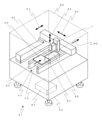
- FIG. 6 shows a schematic perspective view of the coating apparatus 51 according to the embodiment.
- (B1) Configuration A coating apparatus 51 according to an embodiment of the present invention includes the above-described ejection device 1, an XYZ drive mechanism 52 that relatively moves the workpiece 56 that is a target for ejecting the liquid material 14, and the above-described ejection device 1.
- the work 56 is carried from the outside of the coating device 51, moved to the coating work position, and carried to the outside of the coating device 51, the stage 55 for supporting and fixing the work 56 during the coating work, and the operation of each of the above devices
- a coating control device 57 that controls the above.
- the discharge device 1 is installed on the XYZ drive mechanism 52 and can move in the directions (X movement direction 60, Y movement direction 61, Z movement direction 62) indicated by the respective symbols with respect to the work 56.
- the discharge device 1 can be moved in the XYZ directions.
- the present invention is not limited to this, and any structure may be used as long as the discharge device 1 and the workpiece 56 can be relatively moved.
- the discharge device 1 may be configured to move only in the Z direction, and the stage 55 may be moved in the XY direction.
- the XYZ drive mechanism 52 for example, a servo motor, a combination of a stepping motor and a ball screw, a linear motor, or the like can be adopted.
- the coating apparatus 51 includes a front-rear process apparatus (not shown) and a transport mechanism 53 for delivering a workpiece to and from a loader / unloader.
- the transport mechanism 53 has a structure in which two rail-shaped members 54 having substantially the same width as the work 56 to be transported are installed in parallel, and a belt rotated by a roller (not shown) is provided above the rail-shaped member 54. Is provided.
- the belt is rotated by rotating the roller with a motor or the like, and the work 56 placed on the belt is conveyed in the direction indicated by the reference numerals (loading direction 63, unloading direction 64).
- a substrate may be transferred using a robot having an arm or the like instead of the above-described transport by the belt.
- the stage 55 is provided between the two rail-like members 54 of the transport mechanism 53, and a lift position that supports and fixes the work 56 stopped at the work position so as to be lifted from below. And a lowered position separated from the work 56 so as not to come into contact with the workpiece 56.
- a device for raising and lowering the stage 55 for example, a combination of a motor and a ball screw, an air cylinder, or the like can be used.
- a method of making a plurality of holes communicating from the inside of the stage 55 to the upper surface and sucking and fixing the air by sucking air from the holes, or sandwiching the work 56 with a fixing member A method of fixing the workpiece 56 by fixing the member to the stage 55 by a fixing means such as a screw, and fixing the workpiece 56 so that the workpiece 56 is sandwiched between the holding member (not shown) of the transport mechanism 53 and the stage 55 at the raised position of the stage 55.
- the method to do can be adopted.
- the XYZ drive mechanism 52, the transport mechanism 53, and the stage 55 are provided on a pedestal 58, and the periphery thereof is covered with a cover 59 indicated by a dotted line. By covering with the cover 59, entry of dust from the outside can be prevented, and the safety of the operator can be ensured.
- an opening for taking in and out the work 56 is provided at a position facing the carry-in side and the carry-out side of the transport mechanism 53.
- the discharge control device 10 may be installed inside the gantry 58.
- the application control device 57 that controls the operation of each device includes a processor and a storage device that stores an application control program, and is installed inside the gantry 58 as indicated by a dotted line. Application pattern data necessary for performing the application operation is stored in the storage device of the application control device 57.
- the application control device 57 performs the above-described stirring operation at a predetermined timing in cooperation with the discharge control device 10.
- the linkage between the application control device 57 and the discharge control device 10 is such that the discharge control device 10 controls the operation of equipment necessary for the operation of the discharge device 1 during the discharge operation and the agitation operation, and the application control device 57 controls the discharge operation and the agitation operation. This is performed by instructing the discharge control device 10 at a timing for executing the operation.
- FIG. 7 is a configuration diagram illustrating modules included in the discharge program and the application control program according to the embodiment.
- the application control program transmits a stirring operation command to the discharge control program at the following timing.
- A At the start of work loading / unloading
- B At the time of XYZ movement of the discharge device without discharge (for example, at the time of movement from the standby position to the application start position)
- C A fixed time (for example, a time during which a particle sedimentation problem set by measurement in advance) has occurred since the last discharge operation command or agitation operation command, and the discharge operation command and the agitation operation command are issued.
- the application control device 57 is provided with a timer for detecting the elapse of a fixed time, and when the timer detects the elapse of the fixed time, one or a plurality of stirring operations are performed. (This timer may be implemented by hardware or software.)
- (B2) Operation In the coating apparatus 51 described above, the following coating operation is performed by the coating control program.
- the coating control program When the coating control program is executed, the workpiece 56 is carried into the cover 59 of the coating device 51 by the transport mechanism 53 that transports the workpiece 56 in the first direction.
- the work 56 carried into the cover 59 is conveyed in the first direction as it is, and stops when it is carried to the position (working position) where the stage 55 is installed.
- the stage 55 rises and supports and fixes the work 56.
- the liquid material 14 is continuously discharged onto the work 56 based on a preset application pattern while the discharge device 1 is moved relative to the work 56 by the XYZ drive mechanism 52.
- the application pattern here includes, for example, a case where the liquid material is filled in the dam in a state where the discharge port is moved to a predetermined position and stopped.
- the application control program is programmed to perform the agitation operation using a timing at which this discharge operation is not performed (cannot be performed). For example, since the work 56 is carried in immediately before the application operation (discharge operation), if it is programmed to perform the stirring operation when the work 56 is carried in, the discharge can be performed in a state where solid particles are diffused in the liquid. Great effect. Even when the work is performed only on one workpiece 56, if the stirring operation is programmed when the workpiece 56 is loaded, the timing for performing the stirring operation is not lost.
- the stirring operation command is transmitted to the discharge control device 10 so that the coating operation can be performed in a state where the solid particles are always diffused in the liquid. .
Landscapes
- Life Sciences & Earth Sciences (AREA)
- Engineering & Computer Science (AREA)
- Wood Science & Technology (AREA)
- Chemical & Material Sciences (AREA)
- Chemical Kinetics & Catalysis (AREA)
- Materials Engineering (AREA)
- Organic Chemistry (AREA)
- Coating Apparatus (AREA)
- Application Of Or Painting With Fluid Materials (AREA)
- Led Device Packages (AREA)
- Nozzles (AREA)
Priority Applications (12)
| Application Number | Priority Date | Filing Date | Title |
|---|---|---|---|
| KR1020187001549A KR102494077B1 (ko) | 2015-07-24 | 2016-07-21 | 고체 입자를 함유하는 액체 재료의 토출 장치 및 도포 장치, 및 도포 방법 |
| HK18105932.0A HK1246245A1 (zh) | 2015-07-24 | 2016-07-21 | 含有固体颗粒的液体材料的吐出装置及吐出方法、以及涂布装置 |
| RS20241266A RS66168B1 (sr) | 2015-07-24 | 2016-07-21 | Uređaj za pražnjenje i način pražnjenja tečnog materijala koji sadrži čvrste čestice |
| SG11201800033QA SG11201800033QA (en) | 2015-07-24 | 2016-07-21 | Discharge device and discharge method for liquid material containing solid particles, and coating device |
| US15/746,108 US10799906B2 (en) | 2015-07-24 | 2016-07-21 | Discharge device and discharge method for liquid material containing solid particles, and coating device |
| CN201680043583.3A CN107847962A (zh) | 2015-07-24 | 2016-07-21 | 含有固体颗粒的液体材料的吐出装置及吐出方法、以及涂布装置 |
| PL16830409.5T PL3326723T3 (pl) | 2015-07-24 | 2016-07-21 | Urządzenie uwalniające i sposób uwalniania ciekłego materiału zawierającego cząstki stałe |
| EP16830409.5A EP3326723B1 (de) | 2015-07-24 | 2016-07-21 | Entladungsvorrichtung und entladungsverfahren für flüssigmaterial mit feststoffpartikeln |
| RU2018105697A RU2706311C2 (ru) | 2015-07-24 | 2016-07-21 | Выпускное устройство и способ выпуска для жидкого материала, содержащего твердые частицы, и устройство для нанесения покрытий |
| MYPI2018700172A MY192610A (en) | 2015-07-24 | 2016-07-21 | Discharge device and discharge method for liquid material containing solid particles, and coating device |
| CN202411691497.6A CN119237244A (zh) | 2015-07-24 | 2016-07-21 | 含有固体颗粒的液体材料的涂布装置及涂布方法 |
| PH12018550004A PH12018550004A1 (en) | 2015-07-24 | 2018-01-23 | Discharge device and discharge method for liquid material containing solid particles, and coating device |
Applications Claiming Priority (2)
| Application Number | Priority Date | Filing Date | Title |
|---|---|---|---|
| JP2015-146472 | 2015-07-24 | ||
| JP2015146472A JP6538465B2 (ja) | 2015-07-24 | 2015-07-24 | 固体粒子を含有する液体材料の吐出装置および塗布装置並びに塗布方法 |
Publications (1)
| Publication Number | Publication Date |
|---|---|
| WO2017018304A1 true WO2017018304A1 (ja) | 2017-02-02 |
Family
ID=57886908
Family Applications (1)
| Application Number | Title | Priority Date | Filing Date |
|---|---|---|---|
| PCT/JP2016/071342 Ceased WO2017018304A1 (ja) | 2015-07-24 | 2016-07-21 | 固体粒子を含有する液体材料の吐出装置および吐出方法並びに塗布装置 |
Country Status (15)
| Country | Link |
|---|---|
| US (1) | US10799906B2 (de) |
| EP (1) | EP3326723B1 (de) |
| JP (1) | JP6538465B2 (de) |
| KR (1) | KR102494077B1 (de) |
| CN (2) | CN119237244A (de) |
| HK (1) | HK1246245A1 (de) |
| HU (1) | HUE069257T2 (de) |
| MY (1) | MY192610A (de) |
| PH (1) | PH12018550004A1 (de) |
| PL (1) | PL3326723T3 (de) |
| RS (1) | RS66168B1 (de) |
| RU (1) | RU2706311C2 (de) |
| SG (1) | SG11201800033QA (de) |
| TW (1) | TWI717372B (de) |
| WO (1) | WO2017018304A1 (de) |
Cited By (1)
| Publication number | Priority date | Publication date | Assignee | Title |
|---|---|---|---|---|
| WO2017145978A1 (ja) * | 2016-02-24 | 2017-08-31 | 武蔵エンジニアリング株式会社 | 固体粒子を含有する液体材料の吐出装置および吐出方法並びに塗布装置 |
Families Citing this family (11)
| Publication number | Priority date | Publication date | Assignee | Title |
|---|---|---|---|---|
| JP6778426B2 (ja) * | 2016-09-20 | 2020-11-04 | 武蔵エンジニアリング株式会社 | 液体材料吐出装置 |
| CN109285937B (zh) * | 2018-08-16 | 2020-03-20 | 佛山市国星光电股份有限公司 | Led白光器件及其制备方法、led背光模组 |
| US11581547B2 (en) * | 2019-05-29 | 2023-02-14 | Uchicago Argonne, Llc | Electrode ink deposition system for high-throughput polymer electrolyte fuel cell |
| CN110646346A (zh) * | 2019-10-11 | 2020-01-03 | 宁波江丰生物信息技术有限公司 | 一种加油装置 |
| MX2022011288A (es) * | 2020-03-11 | 2022-10-07 | Musashi Eng Inc | Metodo de formacion de pelicula liquida plana y aparato de formacion de pelicula liquida plana. |
| US20210301943A1 (en) * | 2020-03-27 | 2021-09-30 | Illinois Tool Works Inc. | Dispensing unit having fixed flexible diaphragm seal |
| US11246249B2 (en) | 2020-04-15 | 2022-02-08 | Illinois Tool Works Inc. | Tilt and rotate dispenser having strain wave gear system |
| KR102367805B1 (ko) * | 2020-09-15 | 2022-02-25 | (주)에스티아이 | 디스플레이 제조를 위한 초소형 led 프린팅 장치 |
| US11904337B2 (en) | 2021-08-03 | 2024-02-20 | Illinois Tool Works Inc. | Tilt and rotate dispenser having material flow rate control |
| US11805634B2 (en) * | 2021-08-03 | 2023-10-31 | Illinois Tool Works Inc. | Tilt and rotate dispenser having motion control |
| JP7828547B2 (ja) * | 2022-03-02 | 2026-03-12 | 株式会社リコー | 液体吐出ヘッド、ヘッドユニット、液体吐出装置 |
Citations (5)
| Publication number | Priority date | Publication date | Assignee | Title |
|---|---|---|---|---|
| WO2007097154A1 (ja) * | 2006-02-23 | 2007-08-30 | Konica Minolta Holdings, Inc. | 液体塗布装置及びそのメンテナンス方法 |
| JP2010108616A (ja) * | 2008-10-28 | 2010-05-13 | Panasonic Corp | プラズマディスプレイパネルの製造方法およびインクジェット装置 |
| JP4774407B2 (ja) * | 2005-10-21 | 2011-09-14 | 武蔵エンジニアリング株式会社 | 液材吐出装置 |
| JP2012066386A (ja) * | 2010-09-21 | 2012-04-05 | Panasonic Corp | 充填装置 |
| JP2015111636A (ja) * | 2013-12-06 | 2015-06-18 | 日亜化学工業株式会社 | 発光装置及び発光装置の製造方法 |
Family Cites Families (17)
| Publication number | Priority date | Publication date | Assignee | Title |
|---|---|---|---|---|
| US3122272A (en) * | 1960-08-04 | 1964-02-25 | Marsh Lyle | Fluid dispenser |
| US3712591A (en) * | 1971-11-24 | 1973-01-23 | Nasa | Zero gravity liquid mixer |
| US4027785A (en) * | 1976-04-12 | 1977-06-07 | Chicago Commutator, Inc. | Dual pump colorant dispenser |
| JP2706050B2 (ja) | 1994-09-14 | 1998-01-28 | 武蔵エンジニアリング株式会社 | フィラー入り液体材料の吐出装置 |
| US6164499A (en) * | 1999-07-27 | 2000-12-26 | H.E.R.O. Industries A Division Of Middlefield Bancorp Limited | Paint colorant dispenser and valve therefor |
| JP4108353B2 (ja) | 2002-03-29 | 2008-06-25 | ノードソン コーポレーション | 液体吐出方法及び装置 |
| US6811058B2 (en) * | 2002-04-01 | 2004-11-02 | Fluid Management, Inc. | Valve assembly |
| JP5419616B2 (ja) * | 2009-09-25 | 2014-02-19 | 武蔵エンジニアリング株式会社 | 気泡混入防止機構および該機構を備える液体材料吐出装置並びに液体材料吐出方法 |
| JP5779353B2 (ja) * | 2011-01-19 | 2015-09-16 | 武蔵エンジニアリング株式会社 | 液体材料の塗布方法、塗布装置およびプログラム |
| US20140323993A1 (en) * | 2011-03-25 | 2014-10-30 | Leo Pharma A/S | Applicator |
| US9724658B2 (en) * | 2011-03-28 | 2017-08-08 | Fast & Fluid Management B.V. | Method of homogenizing a liquid |
| ITTO20110125U1 (it) * | 2011-11-21 | 2013-05-22 | Stardale Ltd | Apparecchiatura per il dosaggio di liquidi |
| WO2013076849A1 (ja) * | 2011-11-24 | 2013-05-30 | フォイト パテント ゲゼルシャフト ミット ベシュレンクテル ハフツング | コータ用ヘッド |
| JP2013182967A (ja) * | 2012-03-01 | 2013-09-12 | Panasonic Corp | 樹脂塗布方法および樹脂塗布装置 |
| JP6006509B2 (ja) * | 2012-03-08 | 2016-10-12 | 武蔵エンジニアリング株式会社 | 液体定量吐出装置および塗布装置 |
| EP2781257B1 (de) * | 2013-03-18 | 2016-03-16 | Collomix Rühr-und Mischgeräte GmbH | Kanister für pumpfähige Medien, insbesondere für Farbpigmentpräparationen |
| JP6626364B2 (ja) * | 2016-02-24 | 2019-12-25 | 武蔵エンジニアリング株式会社 | 固体粒子を含有する液体材料の吐出装置および吐出方法並びに塗布装置 |
-
2015
- 2015-07-24 JP JP2015146472A patent/JP6538465B2/ja active Active
-
2016
- 2016-07-21 CN CN202411691497.6A patent/CN119237244A/zh active Pending
- 2016-07-21 US US15/746,108 patent/US10799906B2/en active Active
- 2016-07-21 MY MYPI2018700172A patent/MY192610A/en unknown
- 2016-07-21 HU HUE16830409A patent/HUE069257T2/hu unknown
- 2016-07-21 EP EP16830409.5A patent/EP3326723B1/de active Active
- 2016-07-21 KR KR1020187001549A patent/KR102494077B1/ko active Active
- 2016-07-21 RS RS20241266A patent/RS66168B1/sr unknown
- 2016-07-21 HK HK18105932.0A patent/HK1246245A1/zh unknown
- 2016-07-21 WO PCT/JP2016/071342 patent/WO2017018304A1/ja not_active Ceased
- 2016-07-21 PL PL16830409.5T patent/PL3326723T3/pl unknown
- 2016-07-21 SG SG11201800033QA patent/SG11201800033QA/en unknown
- 2016-07-21 CN CN201680043583.3A patent/CN107847962A/zh active Pending
- 2016-07-21 RU RU2018105697A patent/RU2706311C2/ru active
- 2016-07-22 TW TW105123228A patent/TWI717372B/zh active
-
2018
- 2018-01-23 PH PH12018550004A patent/PH12018550004A1/en unknown
Patent Citations (5)
| Publication number | Priority date | Publication date | Assignee | Title |
|---|---|---|---|---|
| JP4774407B2 (ja) * | 2005-10-21 | 2011-09-14 | 武蔵エンジニアリング株式会社 | 液材吐出装置 |
| WO2007097154A1 (ja) * | 2006-02-23 | 2007-08-30 | Konica Minolta Holdings, Inc. | 液体塗布装置及びそのメンテナンス方法 |
| JP2010108616A (ja) * | 2008-10-28 | 2010-05-13 | Panasonic Corp | プラズマディスプレイパネルの製造方法およびインクジェット装置 |
| JP2012066386A (ja) * | 2010-09-21 | 2012-04-05 | Panasonic Corp | 充填装置 |
| JP2015111636A (ja) * | 2013-12-06 | 2015-06-18 | 日亜化学工業株式会社 | 発光装置及び発光装置の製造方法 |
Non-Patent Citations (1)
| Title |
|---|
| See also references of EP3326723A4 * |
Cited By (2)
| Publication number | Priority date | Publication date | Assignee | Title |
|---|---|---|---|---|
| WO2017145978A1 (ja) * | 2016-02-24 | 2017-08-31 | 武蔵エンジニアリング株式会社 | 固体粒子を含有する液体材料の吐出装置および吐出方法並びに塗布装置 |
| TWI765878B (zh) * | 2016-02-24 | 2022-06-01 | 日商武藏工業股份有限公司 | 含有固體粒子之液體材料之吐出裝置及吐出方法暨塗佈裝置 |
Also Published As
| Publication number | Publication date |
|---|---|
| US20180214903A1 (en) | 2018-08-02 |
| KR102494077B1 (ko) | 2023-01-30 |
| PL3326723T3 (pl) | 2024-11-25 |
| HK1246245A1 (zh) | 2018-09-07 |
| RU2706311C2 (ru) | 2019-11-15 |
| CN119237244A (zh) | 2025-01-03 |
| SG11201800033QA (en) | 2018-02-27 |
| RS66168B1 (sr) | 2024-12-31 |
| MY192610A (en) | 2022-08-29 |
| JP2017023958A (ja) | 2017-02-02 |
| CN107847962A (zh) | 2018-03-27 |
| RU2018105697A3 (de) | 2019-10-09 |
| EP3326723A4 (de) | 2019-08-14 |
| JP6538465B2 (ja) | 2019-07-03 |
| PH12018550004A1 (en) | 2018-07-09 |
| EP3326723A1 (de) | 2018-05-30 |
| TW201724562A (zh) | 2017-07-01 |
| RU2018105697A (ru) | 2019-08-27 |
| HUE069257T2 (hu) | 2025-02-28 |
| KR20180032564A (ko) | 2018-03-30 |
| TWI717372B (zh) | 2021-02-01 |
| EP3326723B1 (de) | 2024-09-04 |
| US10799906B2 (en) | 2020-10-13 |
Similar Documents
| Publication | Publication Date | Title |
|---|---|---|
| KR102494077B1 (ko) | 고체 입자를 함유하는 액체 재료의 토출 장치 및 도포 장치, 및 도포 방법 | |
| TWI882221B (zh) | 液體材料之吐出裝置及吐出方法暨塗佈裝置 | |
| US6348124B1 (en) | Delivery of polishing agents in a wafer processing system | |
| TWI584933B (zh) | Resin forming apparatus and resin forming method | |
| TWI574740B (zh) | Liquid material discharge mechanism and liquid material discharge device | |
| CN106687223A (zh) | 用于分配器的阀座 | |
| HK40114265A (zh) | 含有固体颗粒的液体材料的涂布装置及涂布方法 | |
| KR20060107311A (ko) | 액체 혼합장치와 그 실린더 유닛 | |
| KR102609761B1 (ko) | 시약 플레이트 간이 생산 설비 | |
| JP2020040068A (ja) | 液体材料の吐出装置および吐出方法並びに塗布装置 | |
| JP2003285267A (ja) | ラップ液供給装置 | |
| HK40049188A (en) | Discharge device for liquid material containing solid particles, discharge method, and coating device | |
| KR102367903B1 (ko) | 가공물 코팅장치 | |
| HK1261093A1 (en) | Discharge device for liquid material containing solid particles, discharge method, and coating device | |
| KR101484286B1 (ko) | 슬롯 다이 코팅 장치 | |
| JP2002110710A (ja) | ボンディングペーストの塗布方法 | |
| HK1175537B (en) | Discharge device and liquid dispensing device, and method for dispensing liquid | |
| JPS58183488A (ja) | 定量吐出制御装置 |
Legal Events
| Date | Code | Title | Description |
|---|---|---|---|
| 121 | Ep: the epo has been informed by wipo that ep was designated in this application |
Ref document number: 16830409 Country of ref document: EP Kind code of ref document: A1 |
|
| ENP | Entry into the national phase |
Ref document number: 20187001549 Country of ref document: KR Kind code of ref document: A |
|
| WWE | Wipo information: entry into national phase |
Ref document number: 15746108 Country of ref document: US |
|
| WWE | Wipo information: entry into national phase |
Ref document number: 12018550004 Country of ref document: PH |
|
| NENP | Non-entry into the national phase |
Ref country code: DE |
|
| WWE | Wipo information: entry into national phase |
Ref document number: 2018105697 Country of ref document: RU Ref document number: 2016830409 Country of ref document: EP |
|
| WWE | Wipo information: entry into national phase |
Ref document number: P-2024/1266 Country of ref document: RS |
|
| WWG | Wipo information: grant in national office |
Ref document number: P-2024/1266 Country of ref document: RS |