EP3327367B1 - Lüftungsvorrichtung, insbesondere für wohnung - Google Patents
Lüftungsvorrichtung, insbesondere für wohnung Download PDFInfo
- Publication number
- EP3327367B1 EP3327367B1 EP17199405.6A EP17199405A EP3327367B1 EP 3327367 B1 EP3327367 B1 EP 3327367B1 EP 17199405 A EP17199405 A EP 17199405A EP 3327367 B1 EP3327367 B1 EP 3327367B1
- Authority
- EP
- European Patent Office
- Prior art keywords
- filter
- drawer
- ventilation device
- holder drawer
- access hatch
- Prior art date
- Legal status (The legal status is an assumption and is not a legal conclusion. Google has not performed a legal analysis and makes no representation as to the accuracy of the status listed.)
- Active
Links
Images



Classifications
-
- F—MECHANICAL ENGINEERING; LIGHTING; HEATING; WEAPONS; BLASTING
- F24—HEATING; RANGES; VENTILATING
- F24F—AIR-CONDITIONING; AIR-HUMIDIFICATION; VENTILATION; USE OF AIR CURRENTS FOR SCREENING
- F24F13/00—Details common to, or for air-conditioning, air-humidification, ventilation or use of air currents for screening
- F24F13/28—Arrangement or mounting of filters
-
- F—MECHANICAL ENGINEERING; LIGHTING; HEATING; WEAPONS; BLASTING
- F24—HEATING; RANGES; VENTILATING
- F24F—AIR-CONDITIONING; AIR-HUMIDIFICATION; VENTILATION; USE OF AIR CURRENTS FOR SCREENING
- F24F7/00—Ventilation
- F24F7/007—Ventilation with forced flow
-
- F—MECHANICAL ENGINEERING; LIGHTING; HEATING; WEAPONS; BLASTING
- F24—HEATING; RANGES; VENTILATING
- F24F—AIR-CONDITIONING; AIR-HUMIDIFICATION; VENTILATION; USE OF AIR CURRENTS FOR SCREENING
- F24F2221/00—Details or features not otherwise provided for
- F24F2221/32—Details or features not otherwise provided for preventing human errors during the installation, use or maintenance, e.g. goofy proof
Definitions
- the invention relates to a ventilation device, in particular for a dwelling.
- a ventilation device comprising at least one hollow body, an air intake inlet in said body, an air exhaust outlet of said body, said body housing internally at least one motorized fan capable of creating a forced circulation of air from the air intake inlet to the air exhaust outlet, at least one heating member of the air flow circulating in said body, a filter holder mounted to sliding between a retracted position and an extended position of the body so as to allow, in the retracted position of the filter-carrying drawer, filtration and heating of the air driven by the fan, and an electronic and / or computer system of control of the motorized fan and the heater.
- a ventilation device of the aforementioned type is well known. Until now, such a ventilation device is designed so that the total disassembly of a part is necessary or possible for the simple change of the filter with the risk of loss of said part or means of fixing this part.
- the document JP 2013134038 discloses a ventilation device in which the sliding filter unit can be detached from the body of the ventilation device.
- An object of the invention is to provide a ventilation device whose design allows to limit access to potentially dangerous parts of the ventilation device without harming the ease of maintenance of the device and its aesthetics.
- the subject of the invention is a ventilation device comprising at least one hollow body, an air intake inlet in said body, an air exhaust outlet of said body, said body housing internally at least a motorized fan adapted to create a forced circulation of air from the air intake inlet to the air exhaust outlet, at least one heating member of the air flow circulating in said body, a drawer filter holder movably mounted to slide between a retracted position and an outlet position of the body so as to allow, in the retracted position of the filter holder, filtration and heating of the air driven by the fan, and a system electronic and / or computer control of the motorized fan and the heater, characterized in that the body is equipped with an access door inside said body, in that the access door is couplable audit body by i at least one fixing member, in that the front of the filter-holder drawer masks, in the retracted position of the filter-holder drawer, the fastener or bodies for fixing the access door to the body and in that the device comprises at least one end stop of the filter-holder drawer
- the access hatch and the front of the filter-holder drawer are arranged on the same face of the body, and the access door is provided along its edge adjacent to the front of the body.
- filter drawer a return towards the interior of the body, this return preventing or limiting access to the interior of the body via the filter holder at least in the extended position of the filter holder drawer.
- the or each end stop of the filter-holder drawer in the extended position is an activatable / deactivatable stop, said stop being active in the coupled state of the body access hatch. and inactive in the uncoupled state of the access hatch of the body, to allow a total extraction of the filter holder of the body in the uncoupled state of the access door of the body.
- the or each end stop of the filter-holder drawer in the extended position comprises at least one part, such as a tab, projecting from the internal face, that is to say facing towards the inside of the hollow body, of the access hatch, this at least one projecting portion of the access hatch being arranged on the path followed by a portion of the filter-carrying drawer during the passage of said filter-carrying drawer of the position retracted to the extended position, to form a stopping member in displacement of said filter holder in the direction of an outlet of the filter-holder of the body in the contact position of support of said parts of the access door and the filter drawer.
- the access flap is configured to allow, in the uncoupled state of the body, at least access to said at least one heating element and to the electronic and / or computer control system. motorized fan.
- the front of the filter-holder drawer is equipped with a hole forming a handle inside which at least one finger of an operator is able to be inserted, said hole being closed by a swivel flap.
- the body has at least one open face at least partially closable by a closure plate and the air exhaust outlet is formed at said open face of the body and is formed by a space left free between said body and said at least partial closure plate of said open face of the body.
- said closure plate is provided, on one of its edges, with a closing wing, at said edge of the closure plate, the space left free between closure plate and body, in the state fastened from the closure plate to the body.
- a closing wing at said edge of the closure plate, the space left free between closure plate and body, in the state fastened from the closure plate to the body.
- the body is a polyhedral body and the closure plate is configured to selectively occupy at least two body attachment positions, one in which the wing of the closure plate closes the space between the closure and the face of the body provided with the front of the filter-holder drawer, the other, or another position, in which the wing of the closure plate closes the space between the closure plate and a face of the body other than the one with the front of the filter drawer. Thanks to this variable angular relative positioning of the closure plate and the body, it is possible to take into account the size of the device and to better orient the body and its filter holder according to the environment in which the ventilation device must be arranged while maintaining a lack of blowing down when this is desired.
- the air intake inlet is disposed at a face of the body opposite to the open face of the body at which the air exhaust outlet is formed.
- the body has at least one open face which can be closed at least partially by a fastening plate with a support function for fixing the body to any surface, such as a wall, and said plate of closure is provided with a through opening forming the air intake inlet of said ventilation device.
- said closure plate is provided on its internal face, turned towards the inside of the body, with at least one, preferably a plurality of hooks projecting from said face, and the device comprises, provided for inside the body, at least one, preferably a plurality of lumens, each lumen being configured to allow an associated hook to be housed at least partially within said lumen, in the fixed state of said closure plate to any surface and suspended from the body to said plate by said hooks. It is thus possible to suspend the ventilation device with a masking of the fasteners.
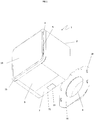
- the ventilation device 1 object of the invention, is more particularly intended to be installed in the volume of a construction to allow variable temperature air supply of said volume.
- This ventilation device 1 comprises a hollow body 2 which is here in the form of a body of parallelepipedal, in particular cubic, shape, with at least two opposite end faces open.
- This hollow body 2 could have been equivalent in the form of a cylindrical body.
- the ventilation device 1 further comprises an air intake inlet 4 and an air exhaust outlet 3 of said body 2 provided at the end faces of the body.
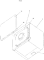
- This body 2 internally houses a motorized fan 5 capable of creating a forced circulation of air from the air intake inlet 4 to the outlet 3 of the exhaust air 2.
- the fan and its engine are presented here under form of a block inserted and fixed by screwing inside the body 2.
- the body 2 still houses a member 6 for heating the flow of air flowing in the body 2.
- This heating member 6 is for example formed by a electrical resistance in the form of a grid disposed opposite the air intake inlet in the fan.
- This heating member 6 is housed in a heating block which further comprises an electronic system 8 and / or computer control of the motorized fan 5 and the heating member 6.
- This electronic system 8 and / or computer control is here in the form of a housing integrated in one of the faces of the heating block.
- This electronic system 8 and / or computer control comprises for example a microcontroller or a microprocessor associated with a memory.
- the electronic and / or computer control system when it is specified that the electronic and / or computer control system is configured to perform a given operation, it means that the system comprises computer instructions and corresponding execution means that make it possible to perform said operation.
- a source of electrical energy is provided for the operation of the assembly.
- the ventilation device 1 is adapted to be equipped with a mains connection cable.
- This electronic or computer control system 8 will not be described in detail because it is well known to those skilled in the art.
- Such an electronic system 8 and / or computer control allows in particular, from a temperature information provided for example by a remote temperature sensor, to control the running or stopping of the heating member.
- the fan is driven at constant speed or controlled speed.
- the block formed of the heating member 6 and the electronic system 8 and / or computer control is inserted into the body 2 of the ventilation device 1.
- the body 2 comprises, from the air inlet inlet 4 to the exhaust outlet 3, the heating unit and the motor-fan unit.
- the body 2 further houses a slide 7 filter holder movably mounted to slide between a retracted position and an extended position of the body 2 so as to allow, in the retracted position of the slide 7 filter holder, filtration of the incoming air by means of filter of the drawer 7 filter holder and a heating of the filtered air, the air filtered and heated being driven in displacement by the fan 5.
- This drawer 7 filter holder comprises a front 71, a rear edge 72, a bottom 73 openwork or open and two sidewalls 74.
- the filter is housed removably inside the drawer 7 filter holder between the front 71 and the rear edge 72 of said drawer.
- This drawer 7 filter holder is equipped with telescopic slides fixed inside the body to allow an outlet of the drawer 7 filter holder of the body in a direction perpendicular to the longitudinal axis of the body.
- the longitudinal axis of the body is taken along the axis interconnecting the inlet 3 of the air inlet and the outlet 4 of the air outlet of the body 2.
- This drawer 7 filter holder is thus able to make protrusion of a lateral face of the body connecting the open end faces of the body.
- this drawer 7 filter holder is placed between the heating block and the air intake inlet 4 in the body to allow filtration of the air entering the body 2 before heating and its blowing out of said body.
- the body 2 is further equipped with an access hatch 9 inside said body 2.
- the access hatch 9 and the front 71 of the drawer 7 filter holder are arranged on the same face 2.
- the access hatch 9 is removably mounted on the body 2 and is couplable to said body 2 via fastening members 10 formed here of screws. These fasteners 10 are positioned so that the front 71 of the filter holder drawer masks, in the retracted position of the drawer 7 filter holder, the fastening members 10.
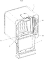
- the device 1 comprises at least one, in this case here two end stops 11 of the end of the slide 7 filter holder in the extended position. These end stops 11 are intended to prevent a total extraction of the filter holder 7 of the body 2 at least in the coupled state of the access door 9 to the body 2.
- the access hatch 9 is configured to allow, in the uncoupled state of the body 2, an access at least to said heating member 6 and to the electronic control system 8 and / or computer control system 5 motorized fans that are placed behind said access hatch 9.
- the access hatch 9 is provided along its edge adjacent to the face 71 of the drawer 7 filter holder of a return 91 in direction of the interior of the body 2.
- This return 91 prevents or limits access to the interior of the body 2 via the drawer 7 filter holder at least in the extended position of the drawer 7 filter holder. It is the same in the intermediate position.
- This return 91 extends in the direction of the interior of the body by two angled tabs towards the drawer 7 filter holder adjacent to the hatch 9 access.
- the bent portion of these tabs forms a portion 111 of the access hatch 9 which is arranged on the path followed by the slide 7 filter holder during the passage of the drawer 7 filter holder from the retracted position to the extended position to form a stop member in displacement of said spool 7 in the direction of an outlet of the slider 7 filter holder of the body in the bearing contact position of the portion 111 of the access hatch 9 with a portion shown in 75 of the drawer 7 filter holder.
- the rear edge 72 of the slide 7 filter holder is also equipped with tabs 75 bent extending beyond the rear edge of the drawer 7 filter holder protruding from said rear edge 72, these tabs 75 coming into contact bearing against the portion 111 bent of the hatch 9 access in the extended position of the drawer 7 filter holder.
- This support contact is represented at figure 8 .
- each limit stop 11 is an activatable / deactivatable stop. Indeed, each end stop 11 is active in the coupled state of the hatch 9 to access the body 2, and inactive in the uncoupled state of the access hatch 9 of the body 2, to allow extraction total of the drawer 7 filter holder of the body 2 in the uncoupled state of the access door 9 of the body 2. This therefore results in a multiple cooperation between drawer 7 filter holder and access hatch 9.
- the front 71 of the drawer 7 filter holder is equipped with a hole 12 forming a handle within which at least one finger of an operator is able to be inserted, said hole 12 being closed by a pivoting flap 13.
- This pivoting flap 13 extends in the plane of the facade 71 of the drawer 7 filter holder in the absence of any solicitation.
- a return spring may be provided to recall it in said position.
- the inlet air intake inlet 4 and the air outlet outlet 3 of the body 2 are formed at the end faces of the body 2 so that the inlet intake inlet 4 air is disposed at a face of the body opposite to the open face of the body at which the outlet 3 exhaust air is formed.
- the body 2 has an open end face at least partially closed by a fastening plate 16 to fasten the support function of the body 2 to any surface, such as a wall.
- This plate 16 closing is provided with a through opening forming the inlet 4 of air intake of said device 1 ventilation.
- This through opening of the closure plate 16 is here provided with an outer peripheral rim 17 which allows the positioning of the opening of the plate facing a breakthrough of the wall, this breakthrough of the wall opening to the open air.
- this wall breakthrough is equipped with a sheath.
- This plate 16 closing also allows to fix easily and in good conditions the body 2 to the wall.
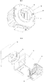
- the plate 16 closing is provided on its inner face, facing the inside of the body 2, four hooks 18 projecting from the face. These hooks 18 each have the shape of an L-shaped hook to form a hook open to the sky in the manner of a hook.
- the device 1 further comprises, formed inside the body 2, four lumens 19. Each lumen 19 is configured to allow an associated hook 18 to be housed at least partially inside said lumen 19, in the state fixed of said closure plate 6 to any surface and suspended from the body 2 to said plate 16 by said hooks 18.
- the number of hooks 18 and lights 19 can vary without departing from the scope of the invention.
- the plate 16 closing is fixed so that the through opening of the plate opens in the open air, via a breakthrough in the wall and then hangs the body 2 to the plate 16 closing via the cooperation hooks / lights 19, the lights 19 affecting the shape of elongated lights in the manner of keyholes so that each light 19, in the state associated with a hook 18, slides along the hook 18 until the hook 18 comes insert into the end of the light 19 forming its upper edge.
- the body 2 is internally provided with at least one locking finger resiliently biased in position protruding from the open face of the body 2 closable at least partially by the plate 16 of closure.
- This locking finger is adapted to fit into an opening of the plate 16 for closing in the fixed state of the closure plate 16 to the body 2 by said hooks 18 to prevent lifting of said body 2.
- This locking member is visible at the figure 8 .
- the open opposite end face of the body 2 is in turn at least partially closable by a closure plate 14 and the air exhaust outlet 3 is formed at said open face of the body 2 and is formed by a space left free between said at least partial closure plate 14 of said open face of the body and said body 2.
- the closure plate 14 is provided on one of its edges with a closing flange 15, at the said edge 14, the closing plate 14, the space left free between the closure plate 14 and the body 2 in the fixed state of the closure plate 14 to the body 2.
- the closure plate 14 is configured to occupy selectively at least two attachment positions to the body 2, namely, a first position, as shown, in which the wing 15 of the closing plate 14 closes the space between the closure plate 14 and the face of the body 2 provided with the front 71 of the filter-holder drawer, and at least one other position, in which the wing 15 of the plate 14 closing the space between plate 14 of closure and a face of the body 2 other than that provided with the front 71 of the drawer 7 filter holder.
- the closure plate 14 is fastened by clipping or snapping as shown in FIG. figure 4 , where four pads 20 are arranged in the open face of the body.
- the drawer 7 filter holder can thus be arranged at the underside of the body 2, as shown, or at a lateral face of the body 2 in the fixed state of the body 2 to a vertical wall, such as 'a wall.
- the procedure is as follows.
- the operator positions his finger at the hole 12 of the front 71 of the drawer 7 filter holder and presses on the flap 13 closing said opening 12 to be able to introduce his finger inside said opening 12. through said opening, it can pull on the drawer to extract said drawer from the body to the end position of the drawer. In this position, the filter can be replaced.
- the operator proceeds as mentioned above. He then uses a screwdriver to remove the access hatch 9. Once this access hatch 9 removed, the drawer 7 filter holder is no longer retained by the hatch 9 and it can also be completely removed. The operator can then perform the maintenance operations he wishes on the rest of the elements arranged inside the body 2.
Landscapes
- Engineering & Computer Science (AREA)
- Chemical & Material Sciences (AREA)
- Combustion & Propulsion (AREA)
- Mechanical Engineering (AREA)
- General Engineering & Computer Science (AREA)
- Cooling Or The Like Of Electrical Apparatus (AREA)
- Ventilation (AREA)
Claims (12)
- Lüftungsvorrichtung (1), umfassend mindestens einen hohlen Körper (2), einen Eingang (4) zum Einlass von Luft in den Körper (2), einen Ausgang (3) zum Auslass von Luft aus dem Körper (2), wobei der Körper (2) mit einer Zugangsklappe (9) zum Inneren des Körpers (2) ausgestattet ist, die mit dem Körper (2) mit Hilfe mindestens eines Fixierungsorgans (10) gekoppelt werden kann, wobei der Körper (2) im Inneren mindestens einen motorisierten Belüfter (5) aufnimmt, der ausgelegt ist, um eine erzwungene Luftzirkulation vom Eingang (4) zum Einlass von Luft hin zum Ausgang (3) zum Auslass von Luft (2) zu erzeugen, wobei die Vorrichtung (1) auch mindestens ein Organ (6) zum Erhitzen des Luftflusses, der in dem Körper (2) zirkuliert, einen Filterhalter-Schieber (7), der gleitend zwischen einer zurückgezogenen Position und einer ausgezogenen Position des Körpers (2) beweglich montiert ist, um in der zurückgezogenen Position des Filterhalter-Schiebers (7) eine Filterung und eine Erhitzung der Luft zu ermöglichen, die vom Belüfter (5) in Bewegung versetzt wurde, und ein elektronisches und/oder Informatiksystem (8) zur Steuerung des motorisierten Belüfters (5) und des Heizorgans (6) umfasst, wobei der Körper (2) mit einer Zugangsklappe (9) zum Inneren des Körpers (2) ausgestattet ist, die mit dem Körper (2) mit Hilfe mindestens eines Fixierungsorgans (10) gekoppelt werden kann, wobei die Vorderseite (71) des Filterhalter-Schiebers (7) in der zurückgezogenen Position des Filterhalter-Schiebers (7) das oder die Fixierungsorgane (10) der Zugangsklappe (9) zum Körper (2) abdeckt, dadurch gekennzeichnet, dass die Vorrichtung (1) mindestens einen Anschlag (11) in der Endlage des Filterhalter-Schiebers (7) in der ausgezogenen Position umfasst, der konfiguriert ist, um ein vollständiges Herausziehen (7) des Filterhalter-Schiebers aus dem Körper (2) mindestens im gekoppelten Zustand der Zugangsklappe (9) zum Körper (2) zu verhindern.
- Lüftungsvorrichtung (1) nach Anspruch 1, dadurch gekennzeichnet, dass die Zugangsklappe (9) und die Abdeckung (71) des Filterhalter-Schiebers (7) an einer gleichen Seite des Körpers (2) angeordnet sind, und dadurch, dass die Zugangsklappe (9) entlang ihrem Rand, benachbart der Abdeckung (71) des Filterhalter-Schiebers (7), mit einer Rückstellung (91) in Richtung des Inneren des Körpers (2) ausgestattet ist, wobei diese Rückstellung (91) den Zugang zum Inneren des Körpers (2) über den Filterhalter-Schublade (7) mindestens in der ausgezogenen Position des Filterhalter-Schiebers (7) verhindert oder begrenzt.
- Lüftungsvorrichtung (1) nach einem der vorhergehenden Ansprüche, dadurch gekennzeichnet, dass der oder jeder Anschlag (11) in der Endlage des Filterhalter-Schiebers (7) in der ausgezogenen Position ein aktivierbarer/deaktivierbarer Anschlag (11) ist, wobei der Anschlag (11) im gekoppelten Zustand der Zugangsklappe zum Körper (2) aktiviert ist und im entkoppelten Zustand der Zugangsklappe (9) zum Körper (2) deaktiviert ist, um ein vollständiges Herausziehen (7) des Filterhalter-Schiebers aus dem Körper (2) im entkoppelten Zustand der Zugangsklappe (9) zum Körper (2) zu ermöglichen.
- Lüftungsvorrichtung (1) nach Anspruch 3, dadurch gekennzeichnet, dass der oder jeder Anschlag (11) in der Endlage des Filterhalter-Schiebers (7) in der ausgezogenen Position mindestens einen Teil (111) wie z. B. einen Fuß umfasst, der sich von der inneren Seite d. h. hin zum Inneren des hohlen Körpers (2) gedreht, die Zugangsklappe (9) hervorspringend, erstreckt, wobei dieser mindestens eine vorspringende Teil (111) der Zugangsklappe (9) auf dem Weg angeordnet ist, dem ein Teil (75) des Filterhalter-Schiebers (7) beim Übergang des Filterhalter-Schiebers (7) aus der zurückgezogenen Position in die ausgezogenen Position folgt, um ein Stopporgan in Verschiebung des Filterhalter-Schiebers (7) in Richtung eines Ausgangs des Filterhalter-Schiebers (7) aus dem Körper in der Auflagekontaktposition der Teile (111, 75) der Zugangsklappe (9) und des Filterhalter-Schiebers (7) zu bilden.
- Lüftungsvorrichtung (1) nach einem der vorhergehenden Ansprüche, dadurch gekennzeichnet, dass die Zugangsklappe (9) konfiguriert ist, um im entkoppelten Zustand des Körpers (2) mindestens einen Zugang zu dem mindestens einen Heizorgan (6) und zum elektronischen oder Informatiksystem (8) zu Steuerung des motorisierten Belüfters (5) zu ermöglichen.
- Lüftungsvorrichtung (1) nach einem der vorhergehenden Ansprüche, dadurch gekennzeichnet, dass die Abdeckung (71) des Filterhalter-Schiebers (7) mit einem Loch (12) ausgestattet ist, das einen Griff bildet, in dessen Inneren mindestens ein Finger eines Bedieners eingeführt werden kann, wobei das Loch (12) durch eine schwenkende Blende (13) verschlossen ist.
- Lüftungsvorrichtung (1) nach einem der vorhergehenden Ansprüche, dadurch gekennzeichnet, dass der Körper (2) mindestens eine offene Seite aufweist, die mindestens teilweise durch eine Verschlussplatte (14) verschlossen werden kann, und dadurch, dass der Ausgang (3) zum Auslass von Luft auf der Ebene der offenen Seite des Körpers (2) angebracht ist und durch einen Raum gebildet ist, der zwischen dem Körper (2) und der Platte (14) zum mindestens teilweisen Verschluss der offenen Seite des Körpers (2) gebildet ist.
- Lüftungsvorichtung (1) nach Anspruch 7, dadurch gekennzeichnet, dass die Verschlussplatte (14) auf einem ihrer Ränder mit einem Flügel (15) ausgestattet ist, der auf der Ebene des Rands der Verschlussplatte (14) den Raum schließt, der zwischen der Verschlussplatte (14) und dem Körper (2) im fixierten Zustand (14) der Verschlussplatte (2) an den Körper freigelassen wurde.
- Lüftungsvorrichtung nach Anspruch 8, dadurch gekennzeichnet, dass der Körper (2) ein polyedrischer Körper ist, und dadurch, dass die Verschlussplatte (14) konfiguriert ist, um selektiv mindestens zwei Fixierungspositionen an den Körper (2) einzunehmen, eine, in der der Flügel (15) der Verschlussplatte (14) den Raum zwischen der Verschlussplatte (14) und der Seite des Körpers (2), die mit der Abdeckung (71) des Filterhalter-Schiebers (7) ausgestattet ist, die andere oder eine andere Position, in der der Flügel (15) der Verschlussplatte (14) den Raum zwischen der Verschlussplatte (14) und einer Seite des Körpers (2) schließt, außer derjenigen, die mit der Abdeckung (71) des Filterhalter-Schiebers (7) ausgestattet ist.
- Lüftungsvorrichtung (1) nach einem der Ansprüche 7 bis 9, dadurch gekennzeichnet, dass der Eingang (4) zum Einlass von Luft auf der Ebene einer Seite des Körpers (2) gegenüber der offenen Seite des Körpers (2) angeordnet ist, auf deren Ebene der Ausgang (3) zum Auslass von Luft angebracht ist.
- Lüftungsvorrichtung (1) nach einem der vorhergehenden Ansprüche, dadurch gekennzeichnet, dass der Körper (2) mindestens eine offene Seite aufweist, die mindestens teilweise durch eine Verschlussplatine (16) verschlossen werden kann, je nach der Stütze zur Fixierung des Körpers (2) an eine beliebige Fläche, wie z. B. eine Mauer, und dadurch, dass die Verschlussplatine (16) mit einer Queröffnung ausgestattet ist, die den Eingang (4) zum Einlass von Luft der Lüftungsvorrichtung (1) bildet.
- Lüftungsvorichtung (1) nach Anspruch 11, dadurch gekennzeichnet, dass die Verschlussplatine (16) auf ihrer als innenliegend bezeichneten Seite, die gegen das Innere des Körpers (2) gerichtet ist, mit mindestens einem, vorzugsweise einer Vielzahl von Haken (18) ausgestattet ist, die von der Seite vorspringen, und dadurch, dass die Vorrichtung (1), angebracht im Inneren des Körpers (2), mindestens eine, vorzugsweise eine Vielzahl von Schlitzen (19) umfasst, wobei jeder Schlitz (19) konfiguriert ist, um einem assoziierten Haken (18) zu ermöglichen, sich im fixierten Zustand der Verschlussplatte (6) an einer beliebigen Fläche, und hängend vom Körper (2) an die Platte (16) durch die Haken (18), mindestens teilweise im Innern der Schlitzes (19) festzusetzen.
Applications Claiming Priority (1)
| Application Number | Priority Date | Filing Date | Title |
|---|---|---|---|
| FR1661454A FR3059085B1 (fr) | 2016-11-24 | 2016-11-24 | Dispositif de ventilation notamment pour habitation |
Publications (2)
| Publication Number | Publication Date |
|---|---|
| EP3327367A1 EP3327367A1 (de) | 2018-05-30 |
| EP3327367B1 true EP3327367B1 (de) | 2019-07-31 |
Family
ID=57963335
Family Applications (1)
| Application Number | Title | Priority Date | Filing Date |
|---|---|---|---|
| EP17199405.6A Active EP3327367B1 (de) | 2016-11-24 | 2017-10-31 | Lüftungsvorrichtung, insbesondere für wohnung |
Country Status (2)
| Country | Link |
|---|---|
| EP (1) | EP3327367B1 (de) |
| FR (1) | FR3059085B1 (de) |
Families Citing this family (2)
| Publication number | Priority date | Publication date | Assignee | Title |
|---|---|---|---|---|
| FR3117433B1 (fr) * | 2020-12-11 | 2023-07-07 | Alstom Transp Tech | Ensemble amélioré constitué d’un tiroir et d’un compartiment de réception du tiroir ; Véhicule associé |
| CN115013907B (zh) * | 2022-06-16 | 2023-08-04 | 青岛平建建筑安装股份有限公司 | 一种绿色建筑的通风节能设备 |
Family Cites Families (8)
| Publication number | Priority date | Publication date | Assignee | Title |
|---|---|---|---|---|
| JPS6062525A (ja) * | 1983-09-14 | 1985-04-10 | Matsushita Electric Ind Co Ltd | 空気調和機のフイルタ装置 |
| JPH0817903B2 (ja) * | 1990-10-22 | 1996-02-28 | ダイキン工業株式会社 | 空気清浄機 |
| FR2741568B1 (fr) * | 1995-11-29 | 1998-01-02 | Valeo Climatisation | Dispositif de filtration d'air pour une installation de chauffage et/ou climatisation de vehicule automobile |
| JP2006159103A (ja) * | 2004-12-08 | 2006-06-22 | Matsushita Electric Ind Co Ltd | 空気浄化ユニット |
| FR2896016B1 (fr) * | 2006-01-10 | 2010-06-11 | Mann & Hummel Gmbh | Filtre a air pour vehicule automobile |
| JP2010204339A (ja) * | 2009-03-03 | 2010-09-16 | Seiko Epson Corp | プロジェクター |
| JP2011257548A (ja) * | 2010-06-08 | 2011-12-22 | Sanyo Electric Co Ltd | エアフィルタ装置及びこれを用いた投写型映像表示装置 |
| JP5674633B2 (ja) * | 2011-12-27 | 2015-02-25 | 三菱電機株式会社 | 換気装置 |
-
2016
- 2016-11-24 FR FR1661454A patent/FR3059085B1/fr not_active Expired - Fee Related
-
2017
- 2017-10-31 EP EP17199405.6A patent/EP3327367B1/de active Active
Non-Patent Citations (1)
| Title |
|---|
| None * |
Also Published As
| Publication number | Publication date |
|---|---|
| EP3327367A1 (de) | 2018-05-30 |
| FR3059085B1 (fr) | 2019-10-18 |
| FR3059085A1 (fr) | 2018-05-25 |
Similar Documents
| Publication | Publication Date | Title |
|---|---|---|
| WO2018037184A1 (fr) | Profile d'accroche permettant le passage d'air et ensemble de plafond comprenant un tel profile | |
| FR2821922A1 (fr) | Dispositif de ventilation multifonction mobile | |
| WO2017103358A1 (fr) | Pulseur d'aspiration destine a un dispositif de chauffage, ventilation et/ou climatisation d'un vehicule automobile et dispositif de chauffage, ventilation et/ou climatisation | |
| FR3059085B1 (fr) | Dispositif de ventilation notamment pour habitation | |
| WO2018076585A1 (zh) | 烤架可自动推出的烤箱 | |
| EP3597036B1 (de) | Schutzvorrichtung für bienenstock, insbesondere vor bienenfressenden insekten | |
| EP3333992B1 (de) | Belüftungsgebläse im innern einer umhüllung zur aufnahme von modularen elektrischen geräten, und umhüllung, die eine solche vorrichtung umfasst | |
| EP1549122B1 (de) | Belüftungssystem eines Gehäuses für elektrische oder elektronische Geräte | |
| FR3093553A1 (fr) | Caisson de répartition d’air | |
| EP2369232A1 (de) | Vorrichtung zum Schutz eines Abgaskanals gegen Wind und/oder Regen, und Abdeckung dafür | |
| EP1909035A1 (de) | Montage einer Brennofenklappe | |
| EP2381060B1 (de) | Device for attaching an accessory element to a main element | |
| EP2843314A1 (de) | Luftzirkulationsvorrichtung, insbesondere für Kaminhaube, und mit einer solchen Vorrichtung ausgestattete Kaminhaube | |
| FR3055405A1 (fr) | Dispositif de circulation d'air notamment pour hotte de cheminee et hotte de cheminee equipee d'un tel dispositif | |
| EP1515091B1 (de) | Einbaubackofen mit belüfteten Seitenwänden | |
| EP1936281B1 (de) | Brennofen, der mindestens einen Verengungsmechanismus für das Durchlassprofil des Luftstroms umfasst | |
| FR3024745A1 (fr) | Volet basculant pour une ouverture de batiment d'elevage et batiment qui en est equipe | |
| FR2913737A1 (fr) | Appareil electromenager comprenant un bandeau de commande et un moyen de verrouillage | |
| EP4040052B1 (de) | System mit heizmodulsatz | |
| FR3030693A1 (fr) | Appareil de chauffage a interface homme-machine embarquee escamotable | |
| EP3604924B1 (de) | Zugbegrenzer | |
| FR2728660A1 (fr) | Bouche d'extraction a double debit pour la ventilation des cuisines et pieces similaires des locaux d'habitation | |
| FR2906872A1 (fr) | Four de cuisson comprenant un dispositif de deflexion d'air. | |
| FR3135333A1 (fr) | Boîtier d’ordinateur à volume modulable | |
| FR2748554A1 (fr) | Appareil de chauffage electrique par rayonnement grand angle |
Legal Events
| Date | Code | Title | Description |
|---|---|---|---|
| PUAI | Public reference made under article 153(3) epc to a published international application that has entered the european phase |
Free format text: ORIGINAL CODE: 0009012 |
|
| STAA | Information on the status of an ep patent application or granted ep patent |
Free format text: STATUS: THE APPLICATION HAS BEEN PUBLISHED |
|
| AK | Designated contracting states |
Kind code of ref document: A1 Designated state(s): AL AT BE BG CH CY CZ DE DK EE ES FI FR GB GR HR HU IE IS IT LI LT LU LV MC MK MT NL NO PL PT RO RS SE SI SK SM TR |
|
| AX | Request for extension of the european patent |
Extension state: BA ME |
|
| STAA | Information on the status of an ep patent application or granted ep patent |
Free format text: STATUS: REQUEST FOR EXAMINATION WAS MADE |
|
| 17P | Request for examination filed |
Effective date: 20181029 |
|
| RBV | Designated contracting states (corrected) |
Designated state(s): AL AT BE BG CH CY CZ DE DK EE ES FI FR GB GR HR HU IE IS IT LI LT LU LV MC MK MT NL NO PL PT RO RS SE SI SK SM TR |
|
| GRAP | Despatch of communication of intention to grant a patent |
Free format text: ORIGINAL CODE: EPIDOSNIGR1 |
|
| STAA | Information on the status of an ep patent application or granted ep patent |
Free format text: STATUS: GRANT OF PATENT IS INTENDED |
|
| INTG | Intention to grant announced |
Effective date: 20190418 |
|
| GRAS | Grant fee paid |
Free format text: ORIGINAL CODE: EPIDOSNIGR3 |
|
| GRAA | (expected) grant |
Free format text: ORIGINAL CODE: 0009210 |
|
| STAA | Information on the status of an ep patent application or granted ep patent |
Free format text: STATUS: THE PATENT HAS BEEN GRANTED |
|
| AK | Designated contracting states |
Kind code of ref document: B1 Designated state(s): AL AT BE BG CH CY CZ DE DK EE ES FI FR GB GR HR HU IE IS IT LI LT LU LV MC MK MT NL NO PL PT RO RS SE SI SK SM TR |
|
| REG | Reference to a national code |
Ref country code: CH Ref legal event code: EP Ref country code: GB Ref legal event code: FG4D Free format text: NOT ENGLISH |
|
| REG | Reference to a national code |
Ref country code: DE Ref legal event code: R096 Ref document number: 602017005700 Country of ref document: DE |
|
| REG | Reference to a national code |
Ref country code: AT Ref legal event code: REF Ref document number: 1161306 Country of ref document: AT Kind code of ref document: T Effective date: 20190815 |
|
| REG | Reference to a national code |
Ref country code: IE Ref legal event code: FG4D Free format text: LANGUAGE OF EP DOCUMENT: FRENCH |
|
| REG | Reference to a national code |
Ref country code: NL Ref legal event code: MP Effective date: 20190731 |
|
| REG | Reference to a national code |
Ref country code: LT Ref legal event code: MG4D |
|
| REG | Reference to a national code |
Ref country code: AT Ref legal event code: MK05 Ref document number: 1161306 Country of ref document: AT Kind code of ref document: T Effective date: 20190731 |
|
| PG25 | Lapsed in a contracting state [announced via postgrant information from national office to epo] |
Ref country code: FI Free format text: LAPSE BECAUSE OF FAILURE TO SUBMIT A TRANSLATION OF THE DESCRIPTION OR TO PAY THE FEE WITHIN THE PRESCRIBED TIME-LIMIT Effective date: 20190731 Ref country code: PT Free format text: LAPSE BECAUSE OF FAILURE TO SUBMIT A TRANSLATION OF THE DESCRIPTION OR TO PAY THE FEE WITHIN THE PRESCRIBED TIME-LIMIT Effective date: 20191202 Ref country code: AT Free format text: LAPSE BECAUSE OF FAILURE TO SUBMIT A TRANSLATION OF THE DESCRIPTION OR TO PAY THE FEE WITHIN THE PRESCRIBED TIME-LIMIT Effective date: 20190731 Ref country code: BG Free format text: LAPSE BECAUSE OF FAILURE TO SUBMIT A TRANSLATION OF THE DESCRIPTION OR TO PAY THE FEE WITHIN THE PRESCRIBED TIME-LIMIT Effective date: 20191031 Ref country code: NL Free format text: LAPSE BECAUSE OF FAILURE TO SUBMIT A TRANSLATION OF THE DESCRIPTION OR TO PAY THE FEE WITHIN THE PRESCRIBED TIME-LIMIT Effective date: 20190731 Ref country code: NO Free format text: LAPSE BECAUSE OF FAILURE TO SUBMIT A TRANSLATION OF THE DESCRIPTION OR TO PAY THE FEE WITHIN THE PRESCRIBED TIME-LIMIT Effective date: 20191031 Ref country code: SE Free format text: LAPSE BECAUSE OF FAILURE TO SUBMIT A TRANSLATION OF THE DESCRIPTION OR TO PAY THE FEE WITHIN THE PRESCRIBED TIME-LIMIT Effective date: 20190731 Ref country code: LT Free format text: LAPSE BECAUSE OF FAILURE TO SUBMIT A TRANSLATION OF THE DESCRIPTION OR TO PAY THE FEE WITHIN THE PRESCRIBED TIME-LIMIT Effective date: 20190731 Ref country code: HR Free format text: LAPSE BECAUSE OF FAILURE TO SUBMIT A TRANSLATION OF THE DESCRIPTION OR TO PAY THE FEE WITHIN THE PRESCRIBED TIME-LIMIT Effective date: 20190731 |
|
| PG25 | Lapsed in a contracting state [announced via postgrant information from national office to epo] |
Ref country code: IS Free format text: LAPSE BECAUSE OF FAILURE TO SUBMIT A TRANSLATION OF THE DESCRIPTION OR TO PAY THE FEE WITHIN THE PRESCRIBED TIME-LIMIT Effective date: 20191130 Ref country code: RS Free format text: LAPSE BECAUSE OF FAILURE TO SUBMIT A TRANSLATION OF THE DESCRIPTION OR TO PAY THE FEE WITHIN THE PRESCRIBED TIME-LIMIT Effective date: 20190731 Ref country code: LV Free format text: LAPSE BECAUSE OF FAILURE TO SUBMIT A TRANSLATION OF THE DESCRIPTION OR TO PAY THE FEE WITHIN THE PRESCRIBED TIME-LIMIT Effective date: 20190731 Ref country code: AL Free format text: LAPSE BECAUSE OF FAILURE TO SUBMIT A TRANSLATION OF THE DESCRIPTION OR TO PAY THE FEE WITHIN THE PRESCRIBED TIME-LIMIT Effective date: 20190731 Ref country code: GR Free format text: LAPSE BECAUSE OF FAILURE TO SUBMIT A TRANSLATION OF THE DESCRIPTION OR TO PAY THE FEE WITHIN THE PRESCRIBED TIME-LIMIT Effective date: 20191101 Ref country code: ES Free format text: LAPSE BECAUSE OF FAILURE TO SUBMIT A TRANSLATION OF THE DESCRIPTION OR TO PAY THE FEE WITHIN THE PRESCRIBED TIME-LIMIT Effective date: 20190731 |
|
| PG25 | Lapsed in a contracting state [announced via postgrant information from national office to epo] |
Ref country code: TR Free format text: LAPSE BECAUSE OF FAILURE TO SUBMIT A TRANSLATION OF THE DESCRIPTION OR TO PAY THE FEE WITHIN THE PRESCRIBED TIME-LIMIT Effective date: 20190731 |
|
| PG25 | Lapsed in a contracting state [announced via postgrant information from national office to epo] |
Ref country code: EE Free format text: LAPSE BECAUSE OF FAILURE TO SUBMIT A TRANSLATION OF THE DESCRIPTION OR TO PAY THE FEE WITHIN THE PRESCRIBED TIME-LIMIT Effective date: 20190731 Ref country code: PL Free format text: LAPSE BECAUSE OF FAILURE TO SUBMIT A TRANSLATION OF THE DESCRIPTION OR TO PAY THE FEE WITHIN THE PRESCRIBED TIME-LIMIT Effective date: 20190731 Ref country code: IT Free format text: LAPSE BECAUSE OF FAILURE TO SUBMIT A TRANSLATION OF THE DESCRIPTION OR TO PAY THE FEE WITHIN THE PRESCRIBED TIME-LIMIT Effective date: 20190731 Ref country code: DK Free format text: LAPSE BECAUSE OF FAILURE TO SUBMIT A TRANSLATION OF THE DESCRIPTION OR TO PAY THE FEE WITHIN THE PRESCRIBED TIME-LIMIT Effective date: 20190731 Ref country code: RO Free format text: LAPSE BECAUSE OF FAILURE TO SUBMIT A TRANSLATION OF THE DESCRIPTION OR TO PAY THE FEE WITHIN THE PRESCRIBED TIME-LIMIT Effective date: 20190731 |
|
| REG | Reference to a national code |
Ref country code: DE Ref legal event code: R119 Ref document number: 602017005700 Country of ref document: DE |
|
| PG25 | Lapsed in a contracting state [announced via postgrant information from national office to epo] |
Ref country code: CZ Free format text: LAPSE BECAUSE OF FAILURE TO SUBMIT A TRANSLATION OF THE DESCRIPTION OR TO PAY THE FEE WITHIN THE PRESCRIBED TIME-LIMIT Effective date: 20190731 Ref country code: SK Free format text: LAPSE BECAUSE OF FAILURE TO SUBMIT A TRANSLATION OF THE DESCRIPTION OR TO PAY THE FEE WITHIN THE PRESCRIBED TIME-LIMIT Effective date: 20190731 Ref country code: IS Free format text: LAPSE BECAUSE OF FAILURE TO SUBMIT A TRANSLATION OF THE DESCRIPTION OR TO PAY THE FEE WITHIN THE PRESCRIBED TIME-LIMIT Effective date: 20200224 Ref country code: MC Free format text: LAPSE BECAUSE OF FAILURE TO SUBMIT A TRANSLATION OF THE DESCRIPTION OR TO PAY THE FEE WITHIN THE PRESCRIBED TIME-LIMIT Effective date: 20190731 Ref country code: SM Free format text: LAPSE BECAUSE OF FAILURE TO SUBMIT A TRANSLATION OF THE DESCRIPTION OR TO PAY THE FEE WITHIN THE PRESCRIBED TIME-LIMIT Effective date: 20190731 |
|
| PLBE | No opposition filed within time limit |
Free format text: ORIGINAL CODE: 0009261 |
|
| STAA | Information on the status of an ep patent application or granted ep patent |
Free format text: STATUS: NO OPPOSITION FILED WITHIN TIME LIMIT |
|
| PG2D | Information on lapse in contracting state deleted |
Ref country code: IS |
|
| PG25 | Lapsed in a contracting state [announced via postgrant information from national office to epo] |
Ref country code: LU Free format text: LAPSE BECAUSE OF NON-PAYMENT OF DUE FEES Effective date: 20191031 Ref country code: DE Free format text: LAPSE BECAUSE OF NON-PAYMENT OF DUE FEES Effective date: 20200501 Ref country code: IS Free format text: LAPSE BECAUSE OF FAILURE TO SUBMIT A TRANSLATION OF THE DESCRIPTION OR TO PAY THE FEE WITHIN THE PRESCRIBED TIME-LIMIT Effective date: 20191030 |
|
| 26N | No opposition filed |
Effective date: 20200603 |
|
| REG | Reference to a national code |
Ref country code: BE Ref legal event code: MM Effective date: 20191031 |
|
| PG25 | Lapsed in a contracting state [announced via postgrant information from national office to epo] |
Ref country code: SI Free format text: LAPSE BECAUSE OF FAILURE TO SUBMIT A TRANSLATION OF THE DESCRIPTION OR TO PAY THE FEE WITHIN THE PRESCRIBED TIME-LIMIT Effective date: 20190731 Ref country code: BE Free format text: LAPSE BECAUSE OF NON-PAYMENT OF DUE FEES Effective date: 20191031 |
|
| PG25 | Lapsed in a contracting state [announced via postgrant information from national office to epo] |
Ref country code: IE Free format text: LAPSE BECAUSE OF NON-PAYMENT OF DUE FEES Effective date: 20191031 |
|
| PG25 | Lapsed in a contracting state [announced via postgrant information from national office to epo] |
Ref country code: CY Free format text: LAPSE BECAUSE OF FAILURE TO SUBMIT A TRANSLATION OF THE DESCRIPTION OR TO PAY THE FEE WITHIN THE PRESCRIBED TIME-LIMIT Effective date: 20190731 |
|
| REG | Reference to a national code |
Ref country code: CH Ref legal event code: PL |
|
| PG25 | Lapsed in a contracting state [announced via postgrant information from national office to epo] |
Ref country code: CH Free format text: LAPSE BECAUSE OF FAILURE TO SUBMIT A TRANSLATION OF THE DESCRIPTION OR TO PAY THE FEE WITHIN THE PRESCRIBED TIME-LIMIT Effective date: 20201031 Ref country code: LI Free format text: LAPSE BECAUSE OF FAILURE TO SUBMIT A TRANSLATION OF THE DESCRIPTION OR TO PAY THE FEE WITHIN THE PRESCRIBED TIME-LIMIT Effective date: 20201031 |
|
| PG25 | Lapsed in a contracting state [announced via postgrant information from national office to epo] |
Ref country code: MT Free format text: LAPSE BECAUSE OF FAILURE TO SUBMIT A TRANSLATION OF THE DESCRIPTION OR TO PAY THE FEE WITHIN THE PRESCRIBED TIME-LIMIT Effective date: 20190731 Ref country code: HU Free format text: LAPSE BECAUSE OF FAILURE TO SUBMIT A TRANSLATION OF THE DESCRIPTION OR TO PAY THE FEE WITHIN THE PRESCRIBED TIME-LIMIT; INVALID AB INITIO Effective date: 20171031 |
|
| GBPC | Gb: european patent ceased through non-payment of renewal fee |
Effective date: 20211031 |
|
| PG25 | Lapsed in a contracting state [announced via postgrant information from national office to epo] |
Ref country code: MK Free format text: LAPSE BECAUSE OF FAILURE TO SUBMIT A TRANSLATION OF THE DESCRIPTION OR TO PAY THE FEE WITHIN THE PRESCRIBED TIME-LIMIT Effective date: 20190731 |
|
| PG25 | Lapsed in a contracting state [announced via postgrant information from national office to epo] |
Ref country code: GB Free format text: LAPSE BECAUSE OF NON-PAYMENT OF DUE FEES Effective date: 20211031 |
|
| PGFP | Annual fee paid to national office [announced via postgrant information from national office to epo] |
Ref country code: FR Payment date: 20251030 Year of fee payment: 9 |