EP4341649B1 - Procédé de mesure de débit soumis à une interférence, débitmètre magnéto-inductif et produit-programme informatique - Google Patents
Procédé de mesure de débit soumis à une interférence, débitmètre magnéto-inductif et produit-programme informatique Download PDFInfo
- Publication number
- EP4341649B1 EP4341649B1 EP22746997.0A EP22746997A EP4341649B1 EP 4341649 B1 EP4341649 B1 EP 4341649B1 EP 22746997 A EP22746997 A EP 22746997A EP 4341649 B1 EP4341649 B1 EP 4341649B1
- Authority
- EP
- European Patent Office
- Prior art keywords
- frequency
- measurement
- signal
- measurement signal
- interference
- Prior art date
- Legal status (The legal status is an assumption and is not a legal conclusion. Google has not performed a legal analysis and makes no representation as to the accuracy of the status listed.)
- Active
Links
Images


Classifications
-
- G—PHYSICS
- G01—MEASURING; TESTING
- G01F—MEASURING VOLUME, VOLUME FLOW, MASS FLOW OR LIQUID LEVEL; METERING BY VOLUME
- G01F1/00—Measuring the volume flow or mass flow of fluid or fluent solid material wherein the fluid passes through a meter in a continuous flow
- G01F1/56—Measuring the volume flow or mass flow of fluid or fluent solid material wherein the fluid passes through a meter in a continuous flow by using electric or magnetic effects
- G01F1/58—Measuring the volume flow or mass flow of fluid or fluent solid material wherein the fluid passes through a meter in a continuous flow by using electric or magnetic effects by electromagnetic flowmeters
-
- G—PHYSICS
- G01—MEASURING; TESTING
- G01F—MEASURING VOLUME, VOLUME FLOW, MASS FLOW OR LIQUID LEVEL; METERING BY VOLUME
- G01F1/00—Measuring the volume flow or mass flow of fluid or fluent solid material wherein the fluid passes through a meter in a continuous flow
- G01F1/56—Measuring the volume flow or mass flow of fluid or fluent solid material wherein the fluid passes through a meter in a continuous flow by using electric or magnetic effects
- G01F1/58—Measuring the volume flow or mass flow of fluid or fluent solid material wherein the fluid passes through a meter in a continuous flow by using electric or magnetic effects by electromagnetic flowmeters
- G01F1/60—Circuits therefor
Definitions
- the invention relates to methods for measuring a flow in a pipe by means of an inductive-magnetic flow meter.
- the invention also relates to a computer program product that is suitable for carrying out at least one such method.
- the invention also relates to a control unit that has such a computer program product and a correspondingly equipped magnetic-inductive flow meter.
- the invention also relates to a computer program product for simulating an operating behavior of such a magnetic-inductive flow meter.
- the publication EN 102 56 103 A1 discloses a method for determining the uncertainty of a measuring method processed with a measuring frequency, which can be used in magnetic-inductive flow meters.
- alternating rectangular pulses are excited and time intervals of these are evaluated.
- a settling is first degenerated.
- EN 10 2019 103 501 A1 shows a method for operating a magnetic-inductive flow meter in which gas bubbles are detected in a measuring tube. Rectangular pulses are generated and evaluated to determine a flow velocity in the measuring tube. In pauses between rectangular pulses, a measuring signal is sampled several times and an average value is calculated from the measuring signals recorded per pause time. Differences between several average values from several periods are calculated and these are compared with a threshold value. When the measuring tube is full, the differences are approximately zero.
- the disclosure document EN 10 2004 031 638 A1 discloses a method for operating a magnetic inductive flow measuring device in which interference signals are minimized.
- a vector product is formed from a received signal spectrum, which includes interference signals, and a reference voltage. Based on this, a useful signal component is determined using an inverse Fourier transformation, which in turn is used to calculate a flow rate.
- the publication DE 694 20 783 T2 discloses an electromagnetic flow meter with a measuring tube and a means for applying an alternating magnetic field.
- the flow meter has sensing means for detecting an electromotive force caused by the magnetic fields.
- the sensing means are designed to detect at several points in time in the same direction in a period.
- WO2021137089 A1 discloses a magnetic inductive flowmeter in which the coils are not arranged symmetrically to the plane in which the voltage sensors are located.
- a digital twin based on a physical model is used to optimize the angles chosen for the installation of the coil and the voltage sensors and to calculate the degree of filling in the pipe.
- Flow meters are used in a variety of applications, such as chemical plants, to determine the flow rate of liquids or gases.
- the flow meters are often subject to interference, which can reduce the measuring accuracy of the flow meters.
- cost-effective flow meters are sought. There is therefore a need for flow meters that are robust are resistant to interference, allow precise measurements and are economical to produce at the same time.
- the invention is based on the object of providing a possibility that offers an improvement in at least one of the aspects outlined.
- a magnetic-inductive flow meter is used which is attached to the pipe.
- the magnetic-inductive flow meter has a magnetic coil through which a magnetic field can be induced in the cross-section of the pipe, which interacts with flowing charged particles in the pipe. This makes it possible to generate an electrical voltage perpendicular to the magnetic field in the cross-section of the pipe, which can be detected by suitably mounted voltage sensors.
- the magnetic coil is excited with a square-wave signal which has a pulse frequency.
- the square-wave signal also called a boxcar signal, can be generated from a superposition of several sinusoidal signals.
- the square-wave signal generates an electrical voltage in the cross-section of the pipe, which is recorded as a measurement signal.
- the measurement signal also essentially has a rectangular shape.
- An amplitude of the measurement signal corresponds to the flow to be measured in the pipe.
- the method includes a second step in which a first measured value section of the measurement signal is recorded.
- the measured value section is a section of the measurement signal in which it at least temporarily assumes the amplitude, i.e. the amplitude value.
- the amplitude in turn depends on a flow speed in the pipe, i.e. the flow.
- the first measured value section includes a first and second subsection, which can be viewed and evaluated separately. In particular, the measurement signal for the first and second subsections can be further processed separately.
- the method further comprises a third step in which, for the first and second subsections of the first measured value section, an average value of the measurement signal is formed.
- an average amplitude value of the measurement signal can be formed as an average value over the first or second subsection.
- a difference between the average values in the first and second subsections is therefore essentially zero if the length is the same.
- the average values in the first and second subsections differ, so that a difference between them deviates from zero.
- the presence of a disturbance is detected in the method according to the invention.
- the disturbance threshold value can be specified, for example, by an input from a user or by an algorithm, so that the sensitivity of such a disturbance detection can be suitably adapted to the respective application. If the presence of a disturbance is detected, the evaluation of the measurement signal can be adjusted in order to precisely measure the flow in the pipe. It is possible to calculate an average value for parts of a measurement signal, i.e. measurement value sections and their sub-ranges, with reduced computational effort.
- the sub-sections are shifted so that, for example, the first and last 25% of the measurement value section belong to the first sub-section and the middle 50% of the measurement value section belongs to the second sub-section.
- the difference between the mean values of the sub-sections is then calculated again.
- the steps described implement quadrature demodulation with a rectangular signal and subsequent low-pass filtering, whereby the differences can be interpreted as real and imaginary parts of the demodulated signal.
- the amount of the complex value then corresponds to the amplitude value of the interference signal.
- the evaluation can be carried out over several periods of the excitation signal. The selection of the sections allows for frequency selectivity of the disturbance detection.
- the method according to the invention can be carried out quickly even on simple hardware due to the averaging and difference calculations.
- the presence of a disturbance in the measurement signal can also be easily identified with a surprisingly high level of reliability.
- a corrected amplitude value can be determined that represents a precise measure of the flow rate in the pipe.
- the square wave signal used to excite the magnetic coil has an inactive phase that is independent of the first and/or second measurement value section.
- the inactive phase lies between two measurement value sections and essentially determines the time interval with which amplitude values of the measurement signal can be generated.
- the polarity of the generated magnetic field is reversed. If a disturbance that is not periodic is detected in the claimed method, the inactive phase can be set in such a way that a desired sampling rate is achieved.
- the magnetic-inductive flow meter can thus be adapted, for example, to another evaluation unit that further processes the measurement results of the magnetic-inductive flow meter.
- the inactive phase can also be shortened in order to achieve an increased sampling rate.
- the technical potential of the magnetic-inductive flow meter is thus further exploited.
- a limit is set for the technical potential of the magnetic-inductive flow meter, which can, however, be fully utilized by the claimed solution.
- the method comprises a further step in which a pulse duration of the square wave signal, i.e. Essentially, the total duration of the respective measured value sections and/or the duration of the inactive phase are adapted, i.e. modified.
- the adaptation is carried out to equalize an interference effect in successive measured value sections.
- the computational effort to compensate for the interference or its interference effect is thereby further reduced, which gives the method increased robustness while at the same time having a broad range of applications.
- the aforementioned compensation can also be carried out over more than two measured value sections. This may be necessary if the interference signal has a low frequency. An amplitude value formed after two measured value sections would then still be subject to errors. Averaging several amplitude values, for example two or four amplitude values, then leads to compensation of the disturbance.
- the first and second sections follow one another, i.e. lie one after the other in time.
- the second section can immediately follow the first section or there can be a time gap between them.
- the first and second sections can also partially overlap in time.
- the first section can begin together with the first measured value section and end after 50% of its total duration.
- the second section can, for example, only begin after 25% of the total duration of the measured value section and end after 75% of the total duration of the measured value section.
- the first measured value section can also have further sections, i.e. a third, fourth, etc. section.
- an average value of the measurement signal can be formed for the first measurement value section and a second measurement value section.
- the average value is formed over the entire first or second measurement value section.
- the first and second measurement value sections can be consecutive measurement value sections in the measurement signal. Accordingly, the first and second measurement value sections can have opposing amplitudes. For example, by appropriately forming the difference between the average values in the first and second measurement value sections, essentially twice the amplitude of the measurement signal, i.e. twice the amplitude value, can be determined. This provides a precise value for the amplitude of the measurement signal with reduced computing effort.
- a very small value is to be expected if the measurement sections have the same length of time. If the length of time is different, appropriate weighting must be carried out. If a very small value is not obtained when summing up, this is an indication of a fault, e.g. a deviation of the magnetic fluxes from the nominal value or an electrochemical reaction at the electrodes. This can indicate a defect or degradation of a component of the magnetic-inductive flow meter.
- the first and second steps are also carried out correspondingly for the second measurement value section.
- the measurement signal is recorded separately for the first and second measurement value section and can be used further.
- a characteristic The size of a measured value section e.g. the mean value of the measurement signal, is modulated as a time series onto a carrier signal, for example by means of quadrature amplitude modulation.
- the carrier signal has a carrier frequency that essentially corresponds to the pulse frequency with which the magnetic coil is excited. From this, a frequency shift compared to a comparison frequency can be determined. In particular, by combining with the comparison frequency, a frequency analysis results in a peak, i.e.
- the combination can be designed as so-called aliasing, among other things. If there is interference that affects the measurement signal, the frequency analysis outlined results in a peak at a frequency that corresponds to a frequency shift between the pulse frequency and the comparison frequency. This makes it possible to determine whether the pulse frequency corresponds to a target value. For example, with a pulse frequency that is coupled to a mains frequency, it is possible to determine whether the existing mains frequency, if there is a disturbance associated with it, corresponds to a nominal mains frequency, in particular 50 Hz or 60 Hz. The existing disturbance when measuring the flow in the pipe can thus be characterized in more detail and thus compensated for in a targeted manner. Furthermore, the steps described can also be carried out for a third, fourth, etc. measurement value section.
- the excitation of the magnetic coil can be interrupted for an adjustable period of time. This can be done by omitting at least one pulse, or in a period of time between two excitations of the magnetic coil. During this time, a residual magnetic field is recorded in the pipe, which is then evaluated. In a normal state, if the magnetic coils are not excited, no technically usable or evaluable measurement signal can be expected. In a faulty state, the received measurement signals correspond to a fault, which is caused, for example, by a magnetic field of a neighboring electrical device. Such detected interference is ignored and/or suppressed during further operation of the magnetic-inductive measuring device when evaluating the measurement signals.
- the cause of the interference can also be diagnosed by evaluating the measurement signals of the residual magnetic field, for example electromagnetic coupling on the lines of the magnetic coil. Overall, a further increase in the measurement accuracy and differentiated self-diagnosis of the magnetic-inductive flow meter can be achieved.
- the method according to the invention is used to measure a flow of a fluid in a pipe to which a magnetic-inductive flow meter is attached.
- the magnetic-inductive flow meter has a magnetic coil through which a magnetic field can be induced in the cross-section of the pipe, which interacts with flowing charged particles in the pipe.
- an electrical voltage can be generated vertically in the magnetic field in the cross-section of the pipe, which can be detected by suitably mounted voltage sensors.
- the magnetic coil is excited with a square-wave signal that has a pulse frequency.
- the square-wave signal also called a boxcar signal, can be generated from a superposition of several sinusoidal signals.
- the square-wave signal generates an electrical voltage in the cross-section of the pipe, which is detected as a measurement signal.
- the measurement signal also has essentially a rectangular shape. An amplitude of the measuring signal corresponds to the flow to be measured in the pipe.
- the method also includes a second step in which a frequency analysis of the measurement signal is carried out.
- the frequency analysis can be carried out in parallel while the method is running.
- the frequency analysis can analyze the measurement signal in the form of a time-frequency analysis over time periods that can overlap.
- the frequency analysis in the second step determines frequency components of the measurement signal. Based on this, the frequency components are examined in more detail.
- a frequency component is recognized as a square-wave frequency component, i.e. as caused by the square-wave signal on the magnetic coil, if the corresponding frequency component corresponds to an odd multiple of the pulse frequency.
- the invention is based, among other things, on the knowledge that a square-wave signal is formed as a combination of oscillations whose frequencies correspond, for example, to one, three, five, seven times, etc. of the pulse frequency.
- a disturbance-free measurement signal therefore shows in the frequency analysis only the frequency components outlined above with predictable amplitudes and phases. Furthermore, inactive phases can be defined between their measurement value sections by combining two superimposed square-wave signals.
- a frequency component of the measurement signal is not a square-wave frequency component
- a fourth step is carried out in the method according to the invention. In this step, the corresponding frequency component of the measurement signal is identified as an interference frequency.
- interference frequencies can be identified not only qualitatively, but also quantitatively.
- the method according to the invention is suitable for precisely determining the amplitude value in the measured value section, which allows an exact calculation of the flow in the pipe despite an existing disturbance.
- the method according to the invention is suitable for detecting a defect or degradation of components of the magnetic-inductive flow meter during the frequency analysis of the measurement signal, since the degradation causes the frequency analysis result to deviate from the expected result.
- the method according to the invention is also suitable for identifying different disturbances and consequently has increased robustness.
- the technical potential of the magnetic-inductive flow meter used is thus further exploited.
- a square-wave signal is also understood to mean any signal that has a predictable result in a frequency analysis in which the effects of disturbances and degradations are clearly identifiable.
- the method comprises a further step in which the duration of the measurement value sections is set to an integer multiple of the period duration of an interference signal.
- the durations of inactive phases are adjusted according to the invention.
- the pulse frequency can be adjusted.
- the frequency analysis is designed as a Fourier analysis or as a wavelet analysis. These provide precise information about the properties of the measurement signal as a whole and about selectable sections of the measurement signal, in particular the measurement value sections that may be subject to interference. Furthermore, Fourier analyses and/or wavelet analyses are provided as efficiently implemented functions in a large number of signal processing chips or controllers. This also makes greater use of the technical potential of magnetic-inductive flow meters.
- the claimed method can also be used on existing magnetic-inductive Flow meters can be subsequently implemented as part of a software or firmware update. Accordingly, the technically reasonable service life of existing magnetic-inductive flow meters can be extended cost-effectively using the claimed method. Alternatively, a so-called least squares estimation can be carried out instead of a frequency analysis, which can be carried out quickly with a small number of measurement signals.
- an amplitude, i.e. an amplitude value, of the measurement signal can be determined at least in one measurement value section using the frequency analysis.
- the amplitude of a Fourier-analyzed measurement signal corresponds to the sum of the harmonic oscillations with alternating signs.
- Such a sum can be determined quickly with reduced computational effort.
- additional calculation steps, for example averaging are unnecessary.
- the further step in which the duration of the measured value sections is set to an integer multiple of the period duration of an interference signal comprises adjusting the pulse frequency.
- the task set out at the beginning is also solved by a computer program product according to the invention, which is used to control a magnetic coil and to process measurement signals from a voltage sensor.
- the computer program product has suitable interfaces for this purpose, which allow the corresponding input and output of data or commands.
- the magnetic coil and the voltage sensor are at least functionally part of a magnetic-inductive flow meter.
- the computer program product is also designed to determine, i.e. measure, a flow of a fluid in the cross section of a pipe on which the flow meter is attached.
- the computer program product is designed according to the invention to carry out at least one embodiment of the methods outlined above.
- the computer program product can be executed on a computing unit that interacts with a memory unit.
- the computer program product can be designed monolithically, i.e. carry out all of its functions on one hardware platform.
- the computer program product can also be designed as a system of at least two subprograms that can be executed on different hardware platforms and interact via a communicative data connection.
- Each subprogram comprises at least one function of the computer program product, for example specifying parameter values for the magnetic-inductive flow meter.
- the functionality of the computer program product is realized through this interaction.
- Such subprograms can be executed, for example, on a control unit of the magnetic-inductive flow meter, a master computer, and/or a computer cloud.
- the computer program product can be designed purely as software or hard-wired, for example as a chip, integrated circuit or FPGA.
- the computer program product can also be designed as a combination of these.
- the underlying object is also achieved by a control unit according to the invention.
- the control unit comprises a memory unit and a computer unit, which interact during operation and enable the execution of computer program products allow.
- the control unit is designed to control a magnetic-inductive flow meter and has suitable inputs and outputs for data or commands.
- the control unit is designed to execute a computer program product that is designed according to one of the embodiments set out above.
- the control unit can be designed to implement at least one embodiment of the described methods.
- Such a control unit can be implemented with simple hardware and is therefore particularly cost-efficient. The technical advantages of the underlying methods can thus be achieved to a particular extent.
- the task is also solved by a magnetic-inductive flow meter according to the invention.
- the magnetic-inductive flow meter is designed to measure a flow of a fluid in a cross-section of a pipe and has a magnetic coil and a voltage sensor for this purpose.
- the magnetic coil and the voltage sensor can be actuated or read out via a control unit.
- the control unit is designed according to one of the embodiments outlined above.
- a computer program product according to the invention which is suitable for simulating an operating behavior of a magnetic-inductive flow meter, in particular is designed for this purpose.
- the computer program product can be set up to simulate the operating behavior of the magnetic-inductive flow meter by specifying its structure, i.e. storing an image of it.
- the operating behavior can also be represented by an abstracted calculation model that is independent of the spatial structure of the magnetic-inductive flow meter.
- the operating behavior can also be determined using a combination of these.
- the device to be simulated the magnetic-inductive flow meter is designed according to one of the embodiments described above.
- the computer program product has a physics module for simulation in which the magnetic-inductive flow meter is depicted and, for example, its electrical or signaling behavior can be reproduced under adjustable operating conditions.
- the adjustable operating conditions include a disturbance spectrum with different disturbance frequencies.
- the adjustable operating conditions can include a flow in the cross section of the pipe, a temperature, a pressure, a viscosity in the fluid in the pipe, its conductivity, its induction behavior, magnetic permissivity, a magnetizability.
- the computer program product can have a data interface via which corresponding data can be specified via a user input and/or other simulation-oriented computer program products.
- the computer program product can also have a data interface for outputting simulation results to a user and/or other simulation-oriented computer program products.
- the computer program product can be used to check measurement signals from voltage sensors of the magnetic-inductive flow meter for plausibility.
- the computer program product according to the invention provides a comprehensive and at the same time computing capacity-saving option for monitoring and/or testing a corresponding magnetic-inductive flow meter.
- the computer program product can be designed as a so-called digital twin, as for example in the publication US 2017/286572 A1 described in more detail.
- the disclosure content of US 2017/286572 A1 is incorporated into the present application by reference.
- the computer program product can be monolithic, i.e. can be executed entirely on a hardware platform.
- the computer program product can be modular and comprise a plurality of subprograms that can be executed on separate hardware platforms and interact via a communicative data connection.
- the computer program product can be designed to be executable in a computer cloud.
- the computer program product according to the invention can be used to test and/or optimize a magnetic-inductive flow meter by simulation, for example in the case of a planned retrofit in a system.
- FIG 1 A schematic structure of an embodiment of a magnetic-inductive flow meter 10 according to the invention is shown in FIG 1
- the magnetic-inductive flow meter 10 is mounted on a pipe 11 and is designed to measure a flow 15 through the pipe 11.
- the magnetic-inductive flow meter 10 via magnetic coils 12, which can be excited via a control unit 30.
- the control unit 30 is designed to send excitation signals in the form of square-wave signals 21 to the magnetic coils 12.
- the magnetic coils 12 can generate a variable magnetic field 13 with a pulse frequency 19, with which electrically charged particles 16 in the fluid 18, whose flow 15 is measured, interact.
- the interaction between the electrically charged particles 16 and the magnetic field 13 consists in causing an electrical voltage 17 essentially transverse to the magnetic field 13, which can be detected via voltage sensors 14.
- the detected electrical voltages 17 can be forwarded to the control unit 30 as measurement signals 20.
- the magnetic coils 12 are excited by means of the square-wave signal 21, so that the magnetic field 13 essentially immediately has a predeterminable magnetic flux density, maintains this for a predeterminable pulse duration and then essentially immediately returns to zero.
- Such a square-wave signal 21 designed as a square-wave signal is also referred to as a boxcar signal.
- the magnetic coil 12 is excited in a first step 110, 210 of a method 100, 200 designed to measure the flow 15.
- the electrical voltage 17 is detected by means of the voltage sensors 14 in a second step 120, 220.
- the respective first steps 110, 210 are the same in all methods 100, 200 according to the invention.
- the methods 100, 200 that can be carried out with the control unit 30 are based on the same consideration of the behavior of the detected measurement signals 20, which reflect the induced voltage 17.
- the control unit 30 has a memory unit 52 and a computing unit 54, by means of which a computer program product 50 can be executed, via which at least one of the methods 100, 200 can be implemented.
- the magnetic-inductive flow meter 10 is depicted in a computer program product 80, which is designed as a so-called digital twin.
- This is at least suitable, preferably designed, to simulate the operating behavior of the magnetic-inductive flow meter 10 and for this purpose comprises a structural image of the magnetic-inductive flow meter 10 and/or a mathematical model that reflects its functionality.
- the computer program product 80 for simulating the operating behavior makes it possible, for example, to identify a defective magnetic coil 12 or a defective voltage sensor 14 and/or to check the plausibility of a determined flow 15.
- FIG 1 shows a diagram with a horizontal time axis 23 and a vertical voltage axis 25 as a magnitude axis.
- the graph shows a course of a measurement signal 20, which corresponds to a voltage 17 detected by voltage sensors 14, as for example in FIG 1
- the measuring signal 20 corresponds in its basic form to a square wave signal 21, with which the magnetic coils 12 are connected as in FIG 1 excited.
- the measurement signal 20 comprises measurement value sections 22 which follow one another with alternating orientations. Between the measurement value sections 22 there are inactive phases 28, the durations of which, i.e. their extension along the time axis 23, can be adjusted.
- Each measurement value section 22 has an amplitude value 27 which corresponds to the voltage 17 which is reproduced by the measurement signal 20.
- the amplitude value 27 which corresponds to the existing voltage 17 has a disturbance 29 in the measurement signal 20 which has a disturbance frequency 39. Due to the disturbance 29, the recognition of the correct amplitude value 27 is made more difficult.
- the diagram according to FIG 2 represents a stage of the first method 100 in which the first and second steps 110, 120 have already been carried out and a further evaluation of the measurement signal 20 is to be carried out.
- individual measurement value sections 22, in particular a first and a second measurement value section 24, 26, are examined in more detail.
- FIG 2 The stage of the method 100 shown is simulated in a computer program product 80 which is designed as a digital twin.
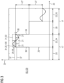
- FIG 3 a stage of the first method 100 according to the invention is shown, which is based on the FIG 2 stage shown follows.
- FIG 3 essentially shows an enlarged section of the diagram from FIG 2 .
- the diagram in FIG 3 also has a time axis 23 and a voltage axis 25, in which the course of the measurement signal 20 is shown.
- a first measurement value section 24 is identified, which is to be evaluated in more detail.
- the first measurement value section 24 is easily recognizable in terms of signal technology, for example, based on its essentially vertical front edge 34 or rear edge 34.
- the first measurement value section 24 is divided into subsections 31, which are to be examined separately.
- an average value 37 of the measurement signal 20 is determined in the third step 130.
- an average value 37 is determined for a second subsection 33 of the first measurement value section 24 in the third step 130.
- the average values 37 are in FIG 3 indicated by broken lines.
- the second section 33 follows directly after the first section 32. Due to the essentially sinusoidal disturbance 29, the average values 37 of the measurement signal 20, i.e. its respective average amplitude value 27, are unequal in the first and second sections 32, 33. By comparing the average values 37 in the first and second sections 32, 33, for example by suitable subtraction, it can be determined that the disturbance 29 is present.
- the presence of the disturbance 29 is recognized when the average values 37 in the first and second sections 32, 33 differ from one another by at least one disturbance threshold value 38.
- the disturbance threshold value 38 is specified by a user or an algorithm that can be designed as a component of the computer program product 50 in the control unit 30.
- other subsections 31 can also be selected as the first or second subsection 32, 33, which can also partially overlap in time.
- the third step 130 can also be carried out correspondingly on a second measured value section 26.
- the formation of the average value 37 can be carried out quickly and easily and represents a meaningful parameter for the method 100.
- the FIG 3 The stage of the method 100 shown is simulated in a computer program product 80 which is designed as a digital twin.
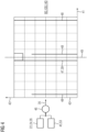
- FIG 4 A further stage of the first method 100 according to the invention is shown in FIG 4
- the stage in FIG 4 assumes that at least the first and second steps 110, 120 are completed and a fourth step 140 can be carried out.
- a carrier signal 45 is provided for the fourth step 140.
- the detected measurement signal 20, as for example in FIG 2 shown, is combined with the carrier signal 45 at least in the scope of the first and second measurement value sections 24, 26 in the course of a modulation 46.
- the modulation 46 is designed as a quadrature amplitude modulation.
- the modulated carrier signal 35 thus obtained is further subjected to a frequency analysis 40 in the course of the fourth step 140, the result of which is FIG 4 is shown as a diagram.
- the diagram comprises a horizontal frequency axis 41 and a vertical magnitude axis 43.
- the diagram is divided by a line that represents the so-called zero frequency, which serves as the comparison frequency 49.
- a peak is to be expected in the frequency analysis 40 at the comparison frequency 49.
- a frequency shift 47 is detected, which quantifies the disturbance 29.
- the amount of the frequency shift 47 i.e. its distance from the comparison frequency 49, corresponds to the disturbance frequency 39 as for example in FIG 2 or FIG 3 shown.
- artifacts 48 are recognized in the frequency analysis 40 so that confusion with an interference frequency 39, i.e. an interference 29, is avoided.
- the artifacts 48 can be predicted mathematically by the computer program product 50 in the control unit 30 based on information on the carrier frequency 53 in conjunction with information on the pulse frequency 19. This ensures that incorrectly diagnosed interference 29 can be avoided in a simple manner.
- a cause of the interference 29 can be deduced.
- the duration of the inactive phases 28 and/or measured value sections 22, as in FIG 2 or FIG 3 shown, so that the disturbing effect of the disturbance 29 for the determination of the flow 15 is minimized.
- the method 100 as shown in FIG 4 allows a reliable and sufficiently precise quantification of the existing disturbance 29, so that targeted countermeasures can be initiated. The method 100 is thus automatically adaptable and therefore robust against disturbances 29.
- the FIG 4 The stage of the method 100 shown is simulated in a computer program product 80 which is designed as a digital twin
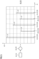
- FIG 5 An embodiment of a second method 200 according to the invention for measuring a flow 15 in a pipe 11 is shown in FIG 5 shown schematically.
- the method 200 assumes that a first step 210, as in FIG 2 shown, has already been carried out. Accordingly, a measurement signal 20 is available from the first step 210, which is then subjected to a frequency analysis 40 in a second step 220.
- the frequency analysis 40 is designed as a Fourier analysis, by means of which frequency components 42 of the measurement signal 20 are recorded.
- the result of the frequency analysis 40 is shown in FIG 5 shown in a diagram that has a horizontal frequency axis 41 and a vertical magnitude axis 43.
- the frequency analysis 40 shows a plurality of frequency components 42, the respective frequency of which is recorded in a third step 230.
- frequency components 42 rectangular frequency components 44 are recognized by the fact that in terms of frequency, i.e. the position of the respective peak 51 on the frequency axis 41, they essentially correspond to an odd multiple of the pulse frequency 19, with which, as in FIG 2 outlined, the variable magnetic field 13 is caused.
- the method 200 is based on the fact that a square-wave signal 21 in a Fourier analysis only has frequency components 42 that correspond to odd multiples of the pulse frequencies 19. Such frequency components 42 can therefore be reliably identified in the method 200. Further frequency components 42 that lie between the square-wave frequency components 44 are identified as interference frequencies 39 in a fourth step 240.
- even-numbered harmonics indicate non-linearities that are coupled to the pulse signal 19. For example, these can be saturation effects in magnetic materials or electrochemical effects.
- Signal components with other frequencies can indicate external interference or defects in the electronics of the device.
- the interference frequencies 39 identified in the method 200 can be removed using suitable filters.
- an amplitude value 27 can be calculated from the rectangular frequency components 44, as for example in FIG 2 outlined, can be determined.
- Frequency analyses 40 in particular Fourier analyses, can be carried out quickly and precisely in a large number of control units 30 for magnetic-inductive flow meters 10. The increasing available computing power of control units 30 is thus used and magnetic-inductive flow meters 10 can be used in demanding environments.
- the method 200 is so device-bound that i.e. decentrally. Higher-level control systems of automation systems are thus relieved of the computing effort involved in flow measurement. This allows a large number of magnetic-inductive flow meters 10 to be used in an automation system without running the risk of them generating excessive testing and correction work in the higher-level control system with incorrect values for the flow 15 to be measured. Consequently, the method 200 enables magnetic-inductive flow meters 10 with which even complex automation systems can be operated in a practical manner.
- the method 200, as in FIG 5 can also be simulated in a computer program product 80 which is designed as a digital twin.
Landscapes
- Physics & Mathematics (AREA)
- Electromagnetism (AREA)
- Fluid Mechanics (AREA)
- General Physics & Mathematics (AREA)
- Measuring Volume Flow (AREA)
Claims (11)
- Procédé (100) de mesure du débit (15) dans un tuyau (11) au moyen d'un débitmètre (10) magnéto-inductif, qui est fixé au tuyau (11), comprenant les stades :a) excitation d'une bobine (12) d'électro-aimant du débitmètre (10) magnéto-inductif par un signal (21) rectangulaire à une fréquence (19) d'impulsion et détection d'un signal (20) de mesure ;b) détection d'une première section (24) de valeur de mesure du signal (20) de mesure, qui comprend une première et une deuxième sections (32, 33) partielles ;c) détermination respectivement d'une valeur (37) moyenne du signal (20) de mesure dans la première et la deuxième sections (32, 33) partielles ;dans lequel on reconnaît une perturbation (29) du signal (20) de mesure si les valeurs (37) moyennes s'écartent l'une de l'autre d'au moins une valeur (38) de seuil de perturbation réglable, caractérisé en ce que le signal (21) rectangulaire a une phase (28) inactive réglable indépendamment de la première et/ou de la deuxième sections (24, 26) de valeur de mesure et, dans un autre stade, on adapte une durée d'impulsion du signal (21) rectangulaire et/ou une durée de la phase (28) inactive à une compensation d'un effet perturbateur dans des sections (22, 24, 26) de valeur de mesure successives.
- Procédé (100) suivant la revendication 1, caractérisé en ce que la première et la deuxième sections (32, 33) partielles se suivent dans le temps ou se chevauchent en partie dans le temps.
- Procédé (100) suivant la revendication 1 ou 2, caractérisé en ce que pour la première section (24) de valeur de mesure et une deuxième section (26) de valeur de mesure, on détermine respectivement une valeur (37) moyenne du signal (20) de mesure, sur la base desquelles on détermine une amplitude (27) du signal (20) de mesure.
- Procédé (100) suivant l'une des revendications 1 à 3, caractérisé en ce que l'on effectue au moins les stades a) et b) également pour la deuxième section (26) de valeur de mesure, dans lequel on module les signaux (20) de mesure de la première et de la deuxième sections (24, 26) de mesure sur un signal (45) de porteuse, dont la fréquence (53) de porteuse correspond à la fréquence (19) d'impulsion et on en détermine un décalage (47) de fréquence par rapport à une fréquence (49) de compensation.
- Procédé (100) suivant la revendication 4, caractérisé en ce que la modulation s'effectue sur le signal (45) de porteuse au moyen d'une modulation d'amplitude en quadrature et/ou la fréquence (49) de compensation est une fréquence de consigne de réseau.
- Procédé (200) de mesure du débit (15) dans un tuyau (11) au moyen d'un débitmètre (10) magnéto-inductif, qui est fixé au tuyau (11), comprenant les stades :a) excitation d'une bobine (12) d'électro-aimant du débitmètre (10) magnéto-inductif par un signal (21) rectangulaire à une fréquence (19) d'impulsion et détection d'un signal (20) de mesure ;b) on effectue une analyse (40) de fréquence du signal (20) de mesure pour la détermination de composantes (42) de fréquence du signal (20) de mesure ;c) on détecte une composante (42) de fréquence du signal (20) de mesure comme composante (44) de fréquence rectangulaire si la composante (42) de fréquence correspond à une fraction en nombre impair de la fréquence (19) d'impulsion ; et sinond) on détecte une composante de fréquence du signal (20) de mesure comme fréquence (39) perturbatrice ;dans lequel, dans un autre stade, on modifie la durée des sections (22) de valeur de mesure à un multiple en nombre entier d'une période de la fréquence (39) perturbatrice, dans lequel on adapte des durées par des phases (28) inactives.
- Procédé (200) suivant la revendication 6, caractérisé en ce que l'analyse (40) de fréquence est constituée sous la forme d'une analyse de Fourier ou d'une analyse d'ondelette.
- Procédé (200) suivant la revendication 6 ou 7, caractérisé en ce que l'on effectue un autre stade e), dans lequel on détermine une amplitude (27) du signal (20) de mesure à l'aide de l'analyse (40) de fréquence.
- Unité (30) de commande d'un débitmètre (10) magnéto-inductif, comprenant une unité (52) de mémoire et une unité (54) informatique pour effectuer un produit (50) de programme d'ordinateur, caractérisée en ce que l'unité (30) de commande est constituée pour exécuter au moins l'un des procédés (100) suivant l'une des revendications 1 à 8.
- Débitmètre (10) magnéto-inductif pour une mesure d'un débit (15) dans un tuyau (11), comprenant une bobine (12) d'électro-aimant et un capteur (14) de tension, qui sont reliés à une unité (30) de commande, caractérisé en ce que l'unité (30) de commande est constituée suivant la revendication 9.
- Produit (80) de programme d'ordinateur pour la simulation d'un comportement de fonctionnement d'un débitmètre (10) magnéto-inductif, caractérisé en ce que le débitmètre (10) est constitué suivant la revendication 10 et le produit (80) de programme d'ordinateur est constitué sous la forme d'un double numérique, dans lequel le produit (80) de programme d'ordinateur dispose d'un module physique, dans lequel le débitmètre (10) magnéto-inductif est représenté et dont le comportement électrique ou en technique du signal peut être réglé dans des conditions de fonctionnement pouvant être données à l'avance, dans lequel les conditions de fonctionnement pouvant être données à l'avance appartiennent à un spectre de perturbation ayant des fréquences perturbatrices différentes et le produit (80) de programme d'ordinateur est constitué pour contrôler la vraisemblance de signaux de mesure de capteur de tension du débitmètre (10) magnéto-inductif afin d'identifier un capteur de tension défectueux.
Applications Claiming Priority (2)
| Application Number | Priority Date | Filing Date | Title |
|---|---|---|---|
| DE102021208598.9A DE102021208598A1 (de) | 2021-08-06 | 2021-08-06 | Verfahren zur störungsbeaufschlagten Durchflussmessung, magnetisch-induktiver Durchflussmesser und Computerprogrammprodukt |
| PCT/EP2022/068953 WO2023011846A1 (fr) | 2021-08-06 | 2022-07-07 | Procédé de mesure de débit soumis à une interférence, débitmètre magnéto-inductif et produit-programme informatique |
Publications (3)
| Publication Number | Publication Date |
|---|---|
| EP4341649A1 EP4341649A1 (fr) | 2024-03-27 |
| EP4341649B1 true EP4341649B1 (fr) | 2024-08-28 |
| EP4341649C0 EP4341649C0 (fr) | 2024-08-28 |
Family
ID=82693903
Family Applications (1)
| Application Number | Title | Priority Date | Filing Date |
|---|---|---|---|
| EP22746997.0A Active EP4341649B1 (fr) | 2021-08-06 | 2022-07-07 | Procédé de mesure de débit soumis à une interférence, débitmètre magnéto-inductif et produit-programme informatique |
Country Status (6)
| Country | Link |
|---|---|
| US (1) | US20240344860A1 (fr) |
| EP (1) | EP4341649B1 (fr) |
| CN (1) | CN117795295A (fr) |
| AU (1) | AU2022321857B2 (fr) |
| DE (1) | DE102021208598A1 (fr) |
| WO (1) | WO2023011846A1 (fr) |
Families Citing this family (2)
| Publication number | Priority date | Publication date | Assignee | Title |
|---|---|---|---|---|
| DE102023102673B3 (de) | 2023-02-03 | 2024-05-16 | Krohne Messtechnik Gmbh | Verfahren zum Betreiben eines magnetisch-induktiven Durchflussmessgeräts und ein entsprechendes magnetisch-induktives Durchflussmessgerät |
| DE102023129076A1 (de) * | 2023-10-23 | 2025-04-24 | Endress+Hauser Conducta Gmbh+Co. Kg | Verfahren zum Bewerten einer Messstelle |
Citations (1)
| Publication number | Priority date | Publication date | Assignee | Title |
|---|---|---|---|---|
| WO2021137089A1 (fr) * | 2019-12-31 | 2021-07-08 | Abb Schweiz Ag | Débitmètre électromagnétique |
Family Cites Families (30)
| Publication number | Priority date | Publication date | Assignee | Title |
|---|---|---|---|---|
| JP3020772B2 (ja) * | 1993-07-09 | 2000-03-15 | 株式会社東芝 | 電磁流量計 |
| US5621177A (en) * | 1995-03-02 | 1997-04-15 | Yokogawa Electric Corporation | Electromagnetic flowmeter |
| DE29511556U1 (de) * | 1995-07-18 | 1995-09-28 | Doll, Friedhelm, Dipl.-Ing., 42929 Wermelskirchen | Induktiver Durchflußmesser |
| US6474158B2 (en) * | 1995-09-19 | 2002-11-05 | Czarnek And Orkin Laboratories, Inc. | Apparatus for measuring displacement and method of use thereof |
| US6615149B1 (en) | 1998-12-10 | 2003-09-02 | Rosemount Inc. | Spectral diagnostics in a magnetic flow meter |
| GB2380798A (en) * | 2001-07-02 | 2003-04-16 | Abb Automation Ltd | Electromagnetic flowmeter |
| JP3915459B2 (ja) * | 2001-09-20 | 2007-05-16 | 横河電機株式会社 | 電磁流量計 |
| DE10256103B4 (de) | 2002-05-14 | 2004-09-16 | Krohne Meßtechnik GmbH & Co KG | Verfahren zur Bestimmung der Unsicherheit eines mit einer Meßfrequenz arbeitenden Meßverfahrens |
| DE102004031638A1 (de) | 2004-06-30 | 2006-01-26 | Abb Patent Gmbh | Verfahren zum Betrieb einer magnetisch induktiven Durchflussmesseinrichtung |
| US7202671B2 (en) * | 2004-08-05 | 2007-04-10 | Kjt Enterprises, Inc. | Method and apparatus for measuring formation conductivities from within cased wellbores by combined measurement of casing current leakage and electromagnetic response |
| DE102005018179A1 (de) * | 2005-04-19 | 2006-10-26 | Krohne Messtechnik Gmbh & Co. Kg | Verfahren zum Betrieb eines Meßgeräts |
| DE102007014469A1 (de) * | 2007-03-22 | 2008-09-25 | Endress + Hauser Flowtec Ag | Verfahren zur vorausschauenden Wartung und/oder Verfahren zur Bestimmung der elektrischen Leitfähigkeit bei einem magnetischinduktiven Durchflussmessgerät |
| US8201625B2 (en) * | 2007-12-26 | 2012-06-19 | Schlumberger Technology Corporation | Borehole imaging and orientation of downhole tools |
| WO2010121631A1 (fr) * | 2009-04-22 | 2010-10-28 | Siemens Aktiengesellschaft | Débitmètre électromagnétique et procédé de fonctionnement de celui-ci |
| JP5444086B2 (ja) * | 2010-03-30 | 2014-03-19 | アズビル株式会社 | 電磁流量計 |
| US9398898B2 (en) * | 2011-02-23 | 2016-07-26 | Siemens Medical Solutions Usa, Inc. | Multiple beam spectral doppler in medical diagnostic ultrasound imaging |
| DE102013114427A1 (de) * | 2013-12-19 | 2015-06-25 | Endress + Hauser Flowtec Ag | Anordnung und Verfahren zur Bestimmung einer durchflussbezogenen Messgröße |
| DE102014010671A1 (de) * | 2014-05-23 | 2015-12-17 | Gerd Reime | Verfahren zur Ermittlung wenigstens eines physikalischen Parameters mittels einer Sensoreinheit |
| CN105806426A (zh) * | 2014-12-31 | 2016-07-27 | 重庆川仪自动化股份有限公司 | 电磁流量计短时励磁及信号处理方法 |
| EP3064905B1 (fr) * | 2015-03-05 | 2019-07-31 | Yokogawa Electric Corporation | Débitmètre électromagnétique |
| US20170286572A1 (en) | 2016-03-31 | 2017-10-05 | General Electric Company | Digital twin of twinned physical system |
| US20180138992A1 (en) * | 2016-11-17 | 2018-05-17 | Baker Hughes Incorporated | Identifying antenna system parameter changes |
| KR20200014411A (ko) * | 2017-06-14 | 2020-02-10 | 마이크로 모우션, 인코포레이티드 | 진동 유량계의 노치 필터 |
| EP3467531A1 (fr) * | 2017-10-05 | 2019-04-10 | Siemens Healthcare GmbH | Appareil d'imagerie par résonance magnétique pourvu de dispositif d'antiparasitage actif et procédé d'antiparasitage dans un appareil d'imagerie par résonance magnétique |
| DE102017131199A1 (de) * | 2017-12-22 | 2019-06-27 | Endress + Hauser Flowtec Ag | Coriolis-Massendurchfluß-Meßgerät |
| DE102019103501B4 (de) | 2018-02-12 | 2022-07-07 | Ifm Electronic Gmbh | Verfahren zum Betreiben eines magnetisch-induktiven Durchflussmessgeräts |
| WO2019234510A1 (fr) * | 2018-06-01 | 2019-12-12 | Nvision Imaging Technologies Gmbh | Systèmes et procédés permettant d'interpréter des signaux de résonance magnétique bruyante d'un tissu, acquis après introduction d'un agent de contraste métabolique |
| US10935402B2 (en) * | 2018-09-06 | 2021-03-02 | Micro Motion, Inc. | Fluid contaminant detection using noise levels in magnetic flow meter sensor signals |
| US11181404B2 (en) * | 2019-09-05 | 2021-11-23 | Micro Motion, Inc. | Magnetic flowmeter with a current sampling circuit sampling coil current pulses at a sampling frequency |
| DE102020123945B4 (de) * | 2020-09-15 | 2023-09-07 | Krohne Messtechnik Gmbh | Verfahren zum Betreiben eines magnetisch-induktiven Durchflussmessgeräts und entsprechendes magnetisch-induktives Durchflussmessgerät |
-
2021
- 2021-08-06 DE DE102021208598.9A patent/DE102021208598A1/de active Pending
-
2022
- 2022-07-07 EP EP22746997.0A patent/EP4341649B1/fr active Active
- 2022-07-07 CN CN202280054941.6A patent/CN117795295A/zh active Pending
- 2022-07-07 US US18/294,681 patent/US20240344860A1/en active Pending
- 2022-07-07 WO PCT/EP2022/068953 patent/WO2023011846A1/fr not_active Ceased
- 2022-07-07 AU AU2022321857A patent/AU2022321857B2/en active Active
Patent Citations (1)
| Publication number | Priority date | Publication date | Assignee | Title |
|---|---|---|---|---|
| WO2021137089A1 (fr) * | 2019-12-31 | 2021-07-08 | Abb Schweiz Ag | Débitmètre électromagnétique |
Also Published As
| Publication number | Publication date |
|---|---|
| AU2022321857B2 (en) | 2025-02-27 |
| WO2023011846A1 (fr) | 2023-02-09 |
| CN117795295A (zh) | 2024-03-29 |
| AU2022321857A1 (en) | 2024-02-08 |
| US20240344860A1 (en) | 2024-10-17 |
| EP4341649A1 (fr) | 2024-03-27 |
| EP4341649C0 (fr) | 2024-08-28 |
| DE102021208598A1 (de) | 2023-02-09 |
Similar Documents
| Publication | Publication Date | Title |
|---|---|---|
| EP3327406B1 (fr) | Procédé de fonctionnement d'un débitmètre massique à accélération de coriolis et débitmètre massique à accélération de coriolis | |
| DE102009002682B4 (de) | Einrichtung und Verfahren zur Residuenauswertung eines Residuums zur Erkennung von Systemfehlern im Systemverhalten eines Systems eines Flugzeugs | |
| EP4341649B1 (fr) | Procédé de mesure de débit soumis à une interférence, débitmètre magnéto-inductif et produit-programme informatique | |
| EP3234512B1 (fr) | Débitmètre à pression différentielle | |
| EP3047241B1 (fr) | Procédé de suivi d'un dispositif de mesure dans l'automatisation industrielle | |
| EP2780671B1 (fr) | Procédé de surveillance de charactéristiques de vibration d'un débitmètre du type coriolis et débitmètre du type coriolis | |
| EP3967988B1 (fr) | Procédé de fonctionnement d'un débitmètre magnétique-inductif et débitmètre magnétique-inductif correspondant | |
| EP2936082B1 (fr) | Débitmètre a vortex et procédé de mesure du taux de vide d'un écoulement multiphasique | |
| EP3559604B1 (fr) | Procédé permettant de faire fonctionner un débitmètre à induction magnétique et débitmètre à induction magnétique | |
| EP2044406B1 (fr) | Procédé pour le diagnostic d'un engorgement d'une ligne d'impulsion d'un convertisseur de pression ainsi que le convertisseur de pression | |
| DE102012016270A1 (de) | Verfahren zum Betrieb mehrerer benachbarter magnetisch-induktiver Durchflussmessgeräte | |
| WO2019110251A1 (fr) | Procédé de détermination de la viscosite d'un milieu au moyen d'un débitmètre massique à effet coriolis et débitmètre massique à effet coriolis pour la mise en œuvre de ce procédé | |
| EP4042111B1 (fr) | Procédé de surveillance d'un système de dispositif de mesure | |
| DE102005033290A1 (de) | Verfahren und Einrichtung zur Erkennung von physikalisch-chemischen Zuständen an Messelektroden eines Durchflussmessers | |
| DE69607693T2 (de) | Verfahren und Anordnung zum Abtasten der Qualitätsänderungen eines Harzbettes | |
| DE102011050716B4 (de) | Verfahren und Vorrichtung zur Online-Messung der Viskosität eines Fluids | |
| EP4296626B1 (fr) | Procédé de fonctionnement d'un débitmètre à induction magnétique et débitmètre à induction magnétique correspondant | |
| EP1363108A2 (fr) | Méthode pour déterminer l'incertitude d'un débitmètre magnéto-inductif | |
| EP3092534B1 (fr) | Système et procédé de surveillance d'un système de production acheminant un fluide | |
| DE10335205A1 (de) | Verfahren zur magnetisch-induktiven Bestimmung der Durchflußrate eines Mediums | |
| DE102021133787A1 (de) | Detektion von Fremdkörpern in fließenden Messmedien | |
| EP4411325B1 (fr) | Procédé de fonctionnement d'un débitmètre à induction magnétique et débitmètre à induction magnétique correspondant | |
| EP4428500B1 (fr) | Procédé de fonctionnement d'un débitmètre à induction magnétique et débitmètre à induction magnétique | |
| DE102009045904A1 (de) | Magnetisch-induktive Durchflussmesseinrichtung und Verfahren zum Betreiben derselben | |
| DE102023105634A1 (de) | Verfahren zum Betreiben eines Magnetisch-induktiven Durchflussmessgeräts und Magnetisch-induktives Durchflussmessgerät |
Legal Events
| Date | Code | Title | Description |
|---|---|---|---|
| STAA | Information on the status of an ep patent application or granted ep patent |
Free format text: STATUS: UNKNOWN |
|
| STAA | Information on the status of an ep patent application or granted ep patent |
Free format text: STATUS: THE INTERNATIONAL PUBLICATION HAS BEEN MADE |
|
| PUAI | Public reference made under article 153(3) epc to a published international application that has entered the european phase |
Free format text: ORIGINAL CODE: 0009012 |
|
| STAA | Information on the status of an ep patent application or granted ep patent |
Free format text: STATUS: REQUEST FOR EXAMINATION WAS MADE |
|
| GRAP | Despatch of communication of intention to grant a patent |
Free format text: ORIGINAL CODE: EPIDOSNIGR1 |
|
| STAA | Information on the status of an ep patent application or granted ep patent |
Free format text: STATUS: GRANT OF PATENT IS INTENDED |
|
| 17P | Request for examination filed |
Effective date: 20231219 |
|
| AK | Designated contracting states |
Kind code of ref document: A1 Designated state(s): AL AT BE BG CH CY CZ DE DK EE ES FI FR GB GR HR HU IE IS IT LI LT LU LV MC MK MT NL NO PL PT RO RS SE SI SK SM TR |
|
| INTG | Intention to grant announced |
Effective date: 20240319 |
|
| GRAS | Grant fee paid |
Free format text: ORIGINAL CODE: EPIDOSNIGR3 |
|
| GRAA | (expected) grant |
Free format text: ORIGINAL CODE: 0009210 |
|
| STAA | Information on the status of an ep patent application or granted ep patent |
Free format text: STATUS: THE PATENT HAS BEEN GRANTED |
|
| AK | Designated contracting states |
Kind code of ref document: B1 Designated state(s): AL AT BE BG CH CY CZ DE DK EE ES FI FR GB GR HR HU IE IS IT LI LT LU LV MC MK MT NL NO PL PT RO RS SE SI SK SM TR |
|
| DAV | Request for validation of the european patent (deleted) | ||
| DAX | Request for extension of the european patent (deleted) | ||
| REG | Reference to a national code |
Ref country code: CH Ref legal event code: EP |
|
| REG | Reference to a national code |
Ref country code: DE Ref legal event code: R096 Ref document number: 502022001583 Country of ref document: DE |
|
| REG | Reference to a national code |
Ref country code: IE Ref legal event code: FG4D Free format text: LANGUAGE OF EP DOCUMENT: GERMAN |
|
| U01 | Request for unitary effect filed |
Effective date: 20240828 |
|
| U07 | Unitary effect registered |
Designated state(s): AT BE BG DE DK EE FI FR IT LT LU LV MT NL PT RO SE SI Effective date: 20240903 |
|
| PG25 | Lapsed in a contracting state [announced via postgrant information from national office to epo] |
Ref country code: NO Free format text: LAPSE BECAUSE OF FAILURE TO SUBMIT A TRANSLATION OF THE DESCRIPTION OR TO PAY THE FEE WITHIN THE PRESCRIBED TIME-LIMIT Effective date: 20241128 |
|
| PG25 | Lapsed in a contracting state [announced via postgrant information from national office to epo] |
Ref country code: GR Free format text: LAPSE BECAUSE OF FAILURE TO SUBMIT A TRANSLATION OF THE DESCRIPTION OR TO PAY THE FEE WITHIN THE PRESCRIBED TIME-LIMIT Effective date: 20241129 Ref country code: PL Free format text: LAPSE BECAUSE OF FAILURE TO SUBMIT A TRANSLATION OF THE DESCRIPTION OR TO PAY THE FEE WITHIN THE PRESCRIBED TIME-LIMIT Effective date: 20240828 |
|
| PG25 | Lapsed in a contracting state [announced via postgrant information from national office to epo] |
Ref country code: IS Free format text: LAPSE BECAUSE OF FAILURE TO SUBMIT A TRANSLATION OF THE DESCRIPTION OR TO PAY THE FEE WITHIN THE PRESCRIBED TIME-LIMIT Effective date: 20241228 |
|
| PG25 | Lapsed in a contracting state [announced via postgrant information from national office to epo] |
Ref country code: HR Free format text: LAPSE BECAUSE OF FAILURE TO SUBMIT A TRANSLATION OF THE DESCRIPTION OR TO PAY THE FEE WITHIN THE PRESCRIBED TIME-LIMIT Effective date: 20240828 |
|
| PG25 | Lapsed in a contracting state [announced via postgrant information from national office to epo] |
Ref country code: ES Free format text: LAPSE BECAUSE OF FAILURE TO SUBMIT A TRANSLATION OF THE DESCRIPTION OR TO PAY THE FEE WITHIN THE PRESCRIBED TIME-LIMIT Effective date: 20240828 Ref country code: RS Free format text: LAPSE BECAUSE OF FAILURE TO SUBMIT A TRANSLATION OF THE DESCRIPTION OR TO PAY THE FEE WITHIN THE PRESCRIBED TIME-LIMIT Effective date: 20241128 |
|
| PG25 | Lapsed in a contracting state [announced via postgrant information from national office to epo] |
Ref country code: RS Free format text: LAPSE BECAUSE OF FAILURE TO SUBMIT A TRANSLATION OF THE DESCRIPTION OR TO PAY THE FEE WITHIN THE PRESCRIBED TIME-LIMIT Effective date: 20241128 Ref country code: PL Free format text: LAPSE BECAUSE OF FAILURE TO SUBMIT A TRANSLATION OF THE DESCRIPTION OR TO PAY THE FEE WITHIN THE PRESCRIBED TIME-LIMIT Effective date: 20240828 Ref country code: NO Free format text: LAPSE BECAUSE OF FAILURE TO SUBMIT A TRANSLATION OF THE DESCRIPTION OR TO PAY THE FEE WITHIN THE PRESCRIBED TIME-LIMIT Effective date: 20241128 Ref country code: IS Free format text: LAPSE BECAUSE OF FAILURE TO SUBMIT A TRANSLATION OF THE DESCRIPTION OR TO PAY THE FEE WITHIN THE PRESCRIBED TIME-LIMIT Effective date: 20241228 Ref country code: HR Free format text: LAPSE BECAUSE OF FAILURE TO SUBMIT A TRANSLATION OF THE DESCRIPTION OR TO PAY THE FEE WITHIN THE PRESCRIBED TIME-LIMIT Effective date: 20240828 Ref country code: GR Free format text: LAPSE BECAUSE OF FAILURE TO SUBMIT A TRANSLATION OF THE DESCRIPTION OR TO PAY THE FEE WITHIN THE PRESCRIBED TIME-LIMIT Effective date: 20241129 Ref country code: ES Free format text: LAPSE BECAUSE OF FAILURE TO SUBMIT A TRANSLATION OF THE DESCRIPTION OR TO PAY THE FEE WITHIN THE PRESCRIBED TIME-LIMIT Effective date: 20240828 |
|
| PG25 | Lapsed in a contracting state [announced via postgrant information from national office to epo] |
Ref country code: SM Free format text: LAPSE BECAUSE OF FAILURE TO SUBMIT A TRANSLATION OF THE DESCRIPTION OR TO PAY THE FEE WITHIN THE PRESCRIBED TIME-LIMIT Effective date: 20240828 |
|
| PG25 | Lapsed in a contracting state [announced via postgrant information from national office to epo] |
Ref country code: CZ Free format text: LAPSE BECAUSE OF FAILURE TO SUBMIT A TRANSLATION OF THE DESCRIPTION OR TO PAY THE FEE WITHIN THE PRESCRIBED TIME-LIMIT Effective date: 20240828 |
|
| PG25 | Lapsed in a contracting state [announced via postgrant information from national office to epo] |
Ref country code: SK Free format text: LAPSE BECAUSE OF FAILURE TO SUBMIT A TRANSLATION OF THE DESCRIPTION OR TO PAY THE FEE WITHIN THE PRESCRIBED TIME-LIMIT Effective date: 20240828 |
|
| PLBE | No opposition filed within time limit |
Free format text: ORIGINAL CODE: 0009261 |
|
| STAA | Information on the status of an ep patent application or granted ep patent |
Free format text: STATUS: NO OPPOSITION FILED WITHIN TIME LIMIT |
|
| 26N | No opposition filed |
Effective date: 20250530 |
|
| U20 | Renewal fee for the european patent with unitary effect paid |
Year of fee payment: 4 Effective date: 20250718 |
|
| REG | Reference to a national code |
Ref country code: CH Ref legal event code: H13 Free format text: ST27 STATUS EVENT CODE: U-0-0-H10-H13 (AS PROVIDED BY THE NATIONAL OFFICE) Effective date: 20260224 |
|
| PG25 | Lapsed in a contracting state [announced via postgrant information from national office to epo] |
Ref country code: CH Free format text: LAPSE BECAUSE OF NON-PAYMENT OF DUE FEES Effective date: 20250731 |