EP3327472A1 - Holographisches optisches element und herstellungsverfahren dafür - Google Patents
Holographisches optisches element und herstellungsverfahren dafür Download PDFInfo
- Publication number
- EP3327472A1 EP3327472A1 EP16827665.7A EP16827665A EP3327472A1 EP 3327472 A1 EP3327472 A1 EP 3327472A1 EP 16827665 A EP16827665 A EP 16827665A EP 3327472 A1 EP3327472 A1 EP 3327472A1
- Authority
- EP
- European Patent Office
- Prior art keywords
- layer
- adjacent layer
- optical element
- holographic optical
- volume hologram
- Prior art date
- Legal status (The legal status is an assumption and is not a legal conclusion. Google has not performed a legal analysis and makes no representation as to the accuracy of the status listed.)
- Granted
Links
Images

Classifications
-
- G—PHYSICS
- G02—OPTICS
- G02B—OPTICAL ELEMENTS, SYSTEMS OR APPARATUS
- G02B5/00—Optical elements other than lenses
- G02B5/32—Holograms used as optical elements
-
- G—PHYSICS
- G02—OPTICS
- G02B—OPTICAL ELEMENTS, SYSTEMS OR APPARATUS
- G02B27/00—Optical systems or apparatus not provided for by any of the groups G02B1/00 - G02B26/00, G02B30/00
- G02B27/01—Head-up displays
- G02B27/0101—Head-up displays characterised by optical features
- G02B27/0103—Head-up displays characterised by optical features comprising holographic elements
-
- G—PHYSICS
- G02—OPTICS
- G02B—OPTICAL ELEMENTS, SYSTEMS OR APPARATUS
- G02B27/00—Optical systems or apparatus not provided for by any of the groups G02B1/00 - G02B26/00, G02B30/00
- G02B27/02—Viewing or reading apparatus
- G02B27/021—Reading apparatus
-
- G—PHYSICS
- G03—PHOTOGRAPHY; CINEMATOGRAPHY; ANALOGOUS TECHNIQUES USING WAVES OTHER THAN OPTICAL WAVES; ELECTROGRAPHY; HOLOGRAPHY
- G03H—HOLOGRAPHIC PROCESSES OR APPARATUS
- G03H1/00—Holographic processes or apparatus using light, infrared or ultraviolet waves for obtaining holograms or for obtaining an image from them; Details peculiar thereto
- G03H1/02—Details of features involved during the holographic process; Replication of holograms without interference recording
-
- G—PHYSICS
- G03—PHOTOGRAPHY; CINEMATOGRAPHY; ANALOGOUS TECHNIQUES USING WAVES OTHER THAN OPTICAL WAVES; ELECTROGRAPHY; HOLOGRAPHY
- G03H—HOLOGRAPHIC PROCESSES OR APPARATUS
- G03H1/00—Holographic processes or apparatus using light, infrared or ultraviolet waves for obtaining holograms or for obtaining an image from them; Details peculiar thereto
- G03H1/02—Details of features involved during the holographic process; Replication of holograms without interference recording
- G03H1/024—Hologram nature or properties
-
- G—PHYSICS
- G03—PHOTOGRAPHY; CINEMATOGRAPHY; ANALOGOUS TECHNIQUES USING WAVES OTHER THAN OPTICAL WAVES; ELECTROGRAPHY; HOLOGRAPHY
- G03H—HOLOGRAPHIC PROCESSES OR APPARATUS
- G03H1/00—Holographic processes or apparatus using light, infrared or ultraviolet waves for obtaining holograms or for obtaining an image from them; Details peculiar thereto
- G03H1/02—Details of features involved during the holographic process; Replication of holograms without interference recording
- G03H1/024—Hologram nature or properties
- G03H1/0248—Volume holograms
-
- G—PHYSICS
- G03—PHOTOGRAPHY; CINEMATOGRAPHY; ANALOGOUS TECHNIQUES USING WAVES OTHER THAN OPTICAL WAVES; ELECTROGRAPHY; HOLOGRAPHY
- G03H—HOLOGRAPHIC PROCESSES OR APPARATUS
- G03H1/00—Holographic processes or apparatus using light, infrared or ultraviolet waves for obtaining holograms or for obtaining an image from them; Details peculiar thereto
- G03H1/02—Details of features involved during the holographic process; Replication of holograms without interference recording
- G03H1/0252—Laminate comprising a hologram layer
- G03H1/0256—Laminate comprising a hologram layer having specific functional layer
-
- G—PHYSICS
- G03—PHOTOGRAPHY; CINEMATOGRAPHY; ANALOGOUS TECHNIQUES USING WAVES OTHER THAN OPTICAL WAVES; ELECTROGRAPHY; HOLOGRAPHY
- G03H—HOLOGRAPHIC PROCESSES OR APPARATUS
- G03H1/00—Holographic processes or apparatus using light, infrared or ultraviolet waves for obtaining holograms or for obtaining an image from them; Details peculiar thereto
- G03H1/02—Details of features involved during the holographic process; Replication of holograms without interference recording
- G03H1/0272—Substrate bearing the hologram
-
- G—PHYSICS
- G03—PHOTOGRAPHY; CINEMATOGRAPHY; ANALOGOUS TECHNIQUES USING WAVES OTHER THAN OPTICAL WAVES; ELECTROGRAPHY; HOLOGRAPHY
- G03H—HOLOGRAPHIC PROCESSES OR APPARATUS
- G03H1/00—Holographic processes or apparatus using light, infrared or ultraviolet waves for obtaining holograms or for obtaining an image from them; Details peculiar thereto
- G03H1/04—Processes or apparatus for producing holograms
- G03H1/0465—Particular recording light; Beam shape or geometry
-
- G—PHYSICS
- G11—INFORMATION STORAGE
- G11B—INFORMATION STORAGE BASED ON RELATIVE MOVEMENT BETWEEN RECORD CARRIER AND TRANSDUCER
- G11B7/00—Recording or reproducing by optical means, e.g. recording using a thermal beam of optical radiation by modifying optical properties or the physical structure, reproducing using an optical beam at lower power by sensing optical properties; Record carriers therefor
- G11B7/24—Record carriers characterised by shape, structure or physical properties, or by the selection of the material
- G11B7/2403—Layers; Shape, structure or physical properties thereof
- G11B7/24035—Recording layers
- G11B7/24044—Recording layers for storing optical interference patterns, e.g. holograms; for storing data in three dimensions [3D], e.g. volume storage
-
- G—PHYSICS
- G11—INFORMATION STORAGE
- G11B—INFORMATION STORAGE BASED ON RELATIVE MOVEMENT BETWEEN RECORD CARRIER AND TRANSDUCER
- G11B7/00—Recording or reproducing by optical means, e.g. recording using a thermal beam of optical radiation by modifying optical properties or the physical structure, reproducing using an optical beam at lower power by sensing optical properties; Record carriers therefor
- G11B7/24—Record carriers characterised by shape, structure or physical properties, or by the selection of the material
- G11B7/241—Record carriers characterised by shape, structure or physical properties, or by the selection of the material characterised by the selection of the material
- G11B7/242—Record carriers characterised by shape, structure or physical properties, or by the selection of the material characterised by the selection of the material of recording layers
- G11B7/244—Record carriers characterised by shape, structure or physical properties, or by the selection of the material characterised by the selection of the material of recording layers comprising organic materials only
- G11B7/245—Record carriers characterised by shape, structure or physical properties, or by the selection of the material characterised by the selection of the material of recording layers comprising organic materials only containing a polymeric component
-
- G—PHYSICS
- G02—OPTICS
- G02B—OPTICAL ELEMENTS, SYSTEMS OR APPARATUS
- G02B27/00—Optical systems or apparatus not provided for by any of the groups G02B1/00 - G02B26/00, G02B30/00
- G02B27/01—Head-up displays
-
- G—PHYSICS
- G02—OPTICS
- G02B—OPTICAL ELEMENTS, SYSTEMS OR APPARATUS
- G02B27/00—Optical systems or apparatus not provided for by any of the groups G02B1/00 - G02B26/00, G02B30/00
- G02B27/02—Viewing or reading apparatus
-
- G—PHYSICS
- G03—PHOTOGRAPHY; CINEMATOGRAPHY; ANALOGOUS TECHNIQUES USING WAVES OTHER THAN OPTICAL WAVES; ELECTROGRAPHY; HOLOGRAPHY
- G03H—HOLOGRAPHIC PROCESSES OR APPARATUS
- G03H1/00—Holographic processes or apparatus using light, infrared or ultraviolet waves for obtaining holograms or for obtaining an image from them; Details peculiar thereto
- G03H1/04—Processes or apparatus for producing holograms
- G03H1/0402—Recording geometries or arrangements
- G03H2001/0439—Recording geometries or arrangements for recording Holographic Optical Element [HOE]
-
- G—PHYSICS
- G03—PHOTOGRAPHY; CINEMATOGRAPHY; ANALOGOUS TECHNIQUES USING WAVES OTHER THAN OPTICAL WAVES; ELECTROGRAPHY; HOLOGRAPHY
- G03H—HOLOGRAPHIC PROCESSES OR APPARATUS
- G03H2250/00—Laminate comprising a hologram layer
- G03H2250/12—Special arrangement of layers
-
- G—PHYSICS
- G03—PHOTOGRAPHY; CINEMATOGRAPHY; ANALOGOUS TECHNIQUES USING WAVES OTHER THAN OPTICAL WAVES; ELECTROGRAPHY; HOLOGRAPHY
- G03H—HOLOGRAPHIC PROCESSES OR APPARATUS
- G03H2250/00—Laminate comprising a hologram layer
- G03H2250/37—Enclosing the photosensitive material
-
- G—PHYSICS
- G03—PHOTOGRAPHY; CINEMATOGRAPHY; ANALOGOUS TECHNIQUES USING WAVES OTHER THAN OPTICAL WAVES; ELECTROGRAPHY; HOLOGRAPHY
- G03H—HOLOGRAPHIC PROCESSES OR APPARATUS
- G03H2260/00—Recording materials or recording processes
- G03H2260/12—Photopolymer
-
- G—PHYSICS
- G03—PHOTOGRAPHY; CINEMATOGRAPHY; ANALOGOUS TECHNIQUES USING WAVES OTHER THAN OPTICAL WAVES; ELECTROGRAPHY; HOLOGRAPHY
- G03H—HOLOGRAPHIC PROCESSES OR APPARATUS
- G03H2270/00—Substrate bearing the hologram
- G03H2270/10—Composition
Definitions
- the present invention relates to a holographic optical element and a method for producing the same.
- a holographic optical element having a volume hologram recording layer functions as a light combiner and is applied to an optical lens, a display element, or the like, and thus there is increasing demand for it.
- a holographic optical element as a display element of head-mounted display or head-up display has high transparency of a volume hologram recording layer, and thus it can be used as a display element of a see-through type (for example, JP 2014-215410 A ).
- the holographic optical element Being accompanied with the increasing demand or diversified uses, the holographic optical element is required to have higher performance and quality items are becoming more diversified.
- high diffraction efficiency of a volume hologram recording layer is required to display information light in the presence of external light (background).
- external light background
- it is required to avoid an occurrence of a ghost by suppressing unnecessary light reflection within a display element.
- Production of a volume hologram recording layer is generally achieved by face-to-face exposure (interference exposure) of a photosensitive layer which is sandwiched between a pair of transparent supports and obtained by coating and drying of a photosensitive composition containing polymerizable monomer with coherent light source, and forming a diffraction grating consisting of areas with high refractive index and low refractive index by allowing an occurrence of polymerization reaction in the photosensitive layer according to interference wave (for example, JP 6-301322 A ).
- interference wave for example, JP 6-301322 A
- the photosensitive composition for a volume hologram recording layer described in the above JP 6-301322 A is excellent in terms of diffractive index modulation for enhancing diffraction efficiency, there is a problem that, as the holographic optical element obtained by sandwiching between a pair of transparent supports has insufficient diffraction efficiency, ghosting may easily occur when it is used as a display element.
- an object of the present invention is to provide a means for suppressing an occurrence of a ghost by enhancing diffraction efficiency of a holographic optical element having a volume hologram recording layer.
- Inventors of the present invention conducted intensive studies. As a result, it was found that the above problem can be solved by a holographic optical element in which a diffraction grating is formed so as to extend to an adjacent layer that is provided to be in contact with a volume hologram recording layer, and the present invention is completed accordingly.
- the present invention is a holographic optical element including: a volume hologram recording layer containing a photopolymer; and at least one adjacent layer which is in contact with the volume hologram recording layer and contains a resin, wherein a diffraction grating is formed so as to extend from the volume hologram recording layer to the adjacent layer.
- a layer containing a polymerizable monomer before holographic exposure is referred to as a photosensitive layer
- a layer having a volume hologram recorded therein by performing holographic exposure for a photosensitive layer is referred to as a volume hologram recording layer.
- a resin composition which is obtained by a polymerization according to application of light irradiation (that is, photocured) to a photosensitive composition containing a polymerizable monomer, a photopolymerization initiator, and a matrix resin or a precursor thereof is referred to as a photopolymer.
- the holographic optical element of the present embodiment has a volume hologram recording layer containing a photopolymer and at least one adjacent layer which is in contact with the volume hologram recording layer and contains a resin, in which a diffraction grating is formed so as to extend from the volume hologram recording layer to the adjacent layer.
- the holographic optical element of the present embodiment having this configuration has enhanced diffraction efficiency so that an occurrence of ghost is suppressed.
- a diffraction grating having a high refractive index region and a low refractive index region is formed in a volume hologram recording layer due to the following phenomenon occurring in a photosensitive layer. Namely, when holographic exposure is carried out, polymerization of a polymerizable monomer in the photosensitive layer is promoted in the exposure part, and thus diffusive movement of a polymerizable monomer occurs such that an interface between the polymerizable monomer and other component is minimized as small as possible, and at the same time, the polymerization occurs additionally. Accordingly, in the photosensitive layer, the photopolymer region and region of other component formed by the polymerization are formed with the same pattern as the interference wave irradiated by holographic exposure.
- a high refractive index region and a low refractive index region are formed in accordance with interference wave, resulting in forming of a diffraction grating (hologram) in a volume hologram recording layer.
- hologram diffraction grating
- those polymerization and diffusive movement phenomenon are not likely to occur near an interface between a photosensitive layer and an adjacent layer, and thus a decrease in diffraction efficiency may be easily caused.
- the diffraction grating is formed so as to extend from the volume hologram recording layer to the adjacent layer, and thus the volume occupied by the diffraction grating is increased. It is believed that the diffraction efficiency is enhanced due to such reasons.
- the diffraction grating formed so as to extend to the adjacent layer yields an unclear interface between a volume hologram recording layer and an adjacent layer, interfacial light reflection hardly occurs, and thus it is also possible that an occurrence of a ghost is suppressed when the holographic optical element is used as an image element.
- the aforementioned mechanism is based on presumption, and the holographic optical element of the present embodiment is not limited by the aforementioned mechanism at all.
- X to Y representing a range means “X or more and Y or less” including both X and Y. Furthermore, unless specifically described otherwise, operations and measurement of physical properties or the like are carried out at conditions including room temperature (20 to 25 °C)/relative humidity of 40 to 50% RH.
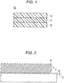
- FIG. 1 is a schematic cross-sectional view illustrating the typical configuration of the holographic optical element of the present embodiment.
- a holographic optical element 10 includes a volume hologram recording layer 11 and a pair of the adjacent layers 12.
- the holographic optical element shown in Fig. 1 has a pair of the adjacent layers 12 provided such that it can be in contact with both surfaces of the volume hologram recording layer 11, but it is also possible to have a configuration in which the adjacent layer 12 is provided only on a single surface of the volume hologram recording layer 11.
- a diffraction grating is formed so as to extend from the volume hologram recording layer to the adjacent layer. Forming of a diffraction grating so as to extend to an adjacent layer can be determined by a method described below, for example.
- Fig. 2 is a schematic view illustrating an exemplary method for measuring the length of a diffraction grating that is formed on an adjacent layer side.
- a holographic optical element 5 is produced such that an adjacent layer 2 has a larger area than a volume hologram recording layer 1.
- the holographic optical element 5 is cut such that an interface between the volume hologram recording layer 1 and the adjacent layer 2 is exposed. Cutting is carried out, after freeze-drying of the holographic optical element 5 with liquid nitrogen, by using a microtome. Accordingly, exposure can be made without disrupting a state near an interface between the volume hologram recording layer 1 and the adjacent layer 2.
- the exposed surface is observed under a transmission electron microscope (TEM), and an extended line 3 is drawn from an end part of the adjacent layer 2 to an interface between the volume hologram recording layer 1 and the adjacent layer 2.
- TEM transmission electron microscope
- the length of the diffraction grating 4 on the adjacent layer 2 side can be obtained by measurement also by TEM for 100 diffraction gratings that are randomly selected and calculation from a mean value of the measurements.
- the length d of the diffraction grating 4 on the adjacent layer 2 side is, although not particularly limited, preferably 1 nm or more, and more preferably 10 nm or more. Furthermore, the upper limit of the length d of the diffraction grating 4 is, although not particularly limited, preferably 50 nm or less, and more preferably 30 nm or less.
- a diffraction grating is formed so as to extend to at least one adjacent layer.
- a method of controlling the density of an adjacent layer a method of modifying affinity or compatibility of an adjacent layer for the polymerizable monomer contained in a photosensitive layer, or the like can be mentioned.
- the adjacent layer contains a resin as a base material.
- the adjacent layer may be provided such that it is in contact with both surfaces of a volume hologram recording layer, or in contact with only one surface of a volume hologram recording layer. Namely, it is sufficient that the holographic optical element of the present embodiment has at least one adjacent layer which is in contact with a volume hologram recording layer and contains a resin.
- constitutional materials and thickness of each adjacent layer may be the same or different from each other.
- the density of an adjacent layer is preferably 1.20 to 1.38 g/cm 3 , and more preferably 1.30 to 1.35 g/cm 3 .
- a photosensitive composition used for forming a volume hologram recording layer described below or a photosensitive layer obtained by coating and drying the photosensitive composition can easily infiltrate an adjacent layer so that a diffraction grating can be easily formed so as to extend to an adjacent layer, in which the diffraction grating is formed by holographic exposure. Accordingly, the diffraction efficiency is further enhanced, and thus an occurrence of a ghost can be further suppressed.
- the density of an adjacent layer can be measured by a method according to the density gradient column method (JIS K-7112-1999). Specifically, the density is calculated according to the following method.
- a glass ball with known density is immersed, and immersion density is measured according to the buoyancy of the ball.
- the same operation is performed for other glass ball with different density, and a calibration curve showing the relationship of depth vs. density is established.
- the adjacent layer according to the present embodiment is immersed in the same bath, immersion depth is determined, and the density of the adjacent layer is calculated by using the calibration curve.
- the measurement based on the density gradient column method described above can be made by using a device for measuring specific gravity which is manufactured by Shibayama Scientific Co., Ltd.
- the resin included in an adjacent layer a known resin with transparency can be used.
- resins include polyolefin such as polyethylene or polypropylene, an acrylic resin such as polymethyl methacrylate (methyl polymethacrylate), cellulose acylate, an acetal resin, polycarbonate, polyurethane, and polyvinyl alcohol. These resins may be used either singly or as a mixture of two or more of them.
- cellulose acylate is preferable.
- the glucose unit which forms ⁇ -1,4 bond to constitute cellulose has a free hydroxyl group at position 2, position 3, and position 6.
- the cellulose acylate is a polymerized product (polymer) in which part or all of those hydroxyl groups are acylated with an acyl group.
- Substitution degree of acylate group indicates the total esterification ratio of cellulose at position 2, position 3, and position 6 of a repeating unit. Specifically, when each hydroxy group of the position 2, position 3, and position 6 of cellulose is 100% esterified, each is determined to have substitution degree of 1. Thus, when all of the position 2, position 3, and position 6 of cellulose are 100% esterified, the substitution degree has the maximum value of 3.
- the substitution degree of acylate group can be measured based on ASTM-D817-96.
- acyl group examples include an acetyl group, an n-propionyl group, an isopropionyl group, an n-butanoyl group, an isobutanoyl group, a t-butanoyl group, a pentanoyl group, a hexanoyl group, a heptanoyl group, an octanoyl group, a decanoyl group, a dodecanoyl group, a tridecanoyl group, a tetradecanoyl group, a hexadecanoyl group, an octadecanoyl group, a cyclohexanecarbonyl group, an oleoyl group, a benzoyl group, a naphthylcarbonyl group, a cinnamoyl group, and an aromatic acyl group represented by the following general formula (I).
- X represents a methyl group, an ethyl group, an n-propyl group, an isopropyl group, an n-butyl group, an isobutyl group, a t-butyl group, a pentyl group, a hexyl group, a heptyl group, or an octyl group
- n is an integer of from 1 to 5, and when n is 2 or higher, a plurality of X may be linked to each other to form a ring.
- an acetyl group, an n-propionyl group, an n-butanoyl group, a t-butanoyl group, a dodecanoyl group, an octadecanoyl group, an oleoyl group, a benzoyl group, a naphthylcarbonyl group, a cinnamoyl group, and an aromatic acyl group represented by the above general formula (I) are more preferable.
- An acetyl group, an n-propionyl group, an n-butanoyl group, a t-butanoyl group, a benzoyl group, and an aromatic acyl group represented by the above general formula (I) are even more preferable, and an acetyl group is particularly preferable.
- the substitution degree of an acetyl group of cellulose acylate is preferably 1.75 to 2.68, and more preferably 2.40 to 2.65.
- Cellulose acylate having an acetyl group may be substituted with, as long as the suitable density range of an adjacent layer described above is satisfied, other acyl group such as an n-propionyl group, an isopropionyl group, an n-butanoyl group, a t-butanoyl group, or a benzoyl group other than an acetyl group.
- the substitution degree of other acyl group is preferably 0.01 to 0.6. With such substitution degree, the density of an adjacent layer can be easily controlled to the above preferred range.
- a benzoyl group is particularly preferable in that it exhibits favorable compatibility with an aromatic ring of a polymerizable monomer that is contained in the photosensitive layer.
- cellulose acylate having a benzoyl group is preferable from the viewpoint in that it allows highly efficient exhibition of the diffusive movement phenomenon of a polymerizable monomer or the like in an adjacent layer and, by further enhancing the diffraction efficiency, further suppresses an occurrence of a ghost.
- the cellulose acylate contains a benzoyl group.
- Weight average molecular weight (Mw) of cellulose acylate is, from the viewpoint of having homogeneous optical properties, productivity, and processability, preferably in the range of 75000 to 280000, and more preferably in the range of 100000 to 240000.
- the weight average molecular weight (Mw) of cellulose acylate can be measured at the following measurement conditions by using gel permeation chromatography (GPC).
- the adjacent layer may contain, within a range in which the density, optical properties, and the like are not impaired, a component other than the aforementioned resin.
- a component other than the aforementioned resin for example, other components including a resin component such as cycloolefin resin or fluorine-containing resin, a UV absorbing agent, an anti-oxidation agent, an anti-degradation agent, a photostabilizer, a heat stabilizer, a lubricating agent, a plasticizer, an anti-static agent, an anti-flame agent, a filler, microparticles, or an optical property modifying agent may be contained.
- the addition amount of other component is preferably 0.1 to 25% by mass relative to the total mass of an adjacent layer.
- the shape of an adjacent layer may be a layer shape like a film shape and plate shape, or a base shape also functioning as a prism.
- a layer shape it can be processed by cutting, and thus there is a convenience that it can be applied to various kinds of an optical element.
- the thickness is, although not particularly limited, preferably 10 to 1000 ⁇ m, and more preferably 50 to 200 ⁇ m.
- the method for forming an adjacent layer in a layer shape like a film shape is not particularly limited, and any conventionally known method including a melt extrusion method, a solution casting method (solution casting), a calendaring method, a compression molding method or the like can be used. Among those methods, a melt extrusion method and a solution casting method (solution casting) are preferable.
- melt extrusion method a method of melt-kneading a resin, and, if necessary, other components followed by molding into a film shape by melt extrusion can be mentioned.
- the kneader used for kneading is not particularly limited, and a conventionally known kneader including an extruder such as a monoaxial extruder or a biaxial extruder, and a pressure kneader can be used.
- a T die method and an inflation method can be mentioned.
- the molding temperature for melt extrusion cannot be generally said as it varies depending on the type of a resin. However, it is preferably 150 to 350°C.
- a film in the case of molding onto a film by T die method, by mounting a T die on a tip part of a known monoaxial extruder or a biaxial extruder and winding a film extruded in a film shape, a film can be obtained in a roll shape.
- a monoaxial stretching step by suitably modifying the temperature of a winding roll and further stretching in an extrusion direction, it is possible to have a monoaxial stretching step.
- a step like sequential biaxial stretching and simultaneous biaxial stretching can be also added.
- it is possible to stabilize optical anisotropy or mechanical properties of a film it is possible to perform a heat treatment (annealing) or the like after stretching treatment.
- solution casting a method of preparing a solution or a dispersion (dope) containing a resin, and, if necessary, other components followed by performing casting can be mentioned.
- the solvent used for a solution casting method is, although not particularly limited, a chlorine-based solvent such as chloroform or methylene chloride; an aromatic solvent such as toluene, xylene, benzene, and a mixed solvent thereof; an alcohol-based solvent such as methanol, ethanol, n-propanol, 2-propanol, n-butanol, sec-butanol, t-butanol, 2,2,2-trifluoroethanol, 2,2,3,3-tetrafluoro-1-propanol, 1,3-difluoro-2-propanol, 1,1,1,3,3,3-hexafluoro-2-methyl-2-propanol, 1,1,1,3,3,3-hexafluoro-2-propanol, or 2,2,3,3,3-pentafluoro-1-propanol; methyl cellosolve, ethyl cellosolve, butyl cellosolve, dimethyl formamide, dimethyl
- solvents may be used either singly or in combination of two or more kinds thereof.
- a solution casting method solution casting
- a stainless band a drum type casting machine, a band type casting machine, and a spin coater can be mentioned.
- an adjacent layer is formed preferably by carrying out the film forming based on a method which includes a step of casting a dope on the aforementioned device, a step of drying the cast dope using a web, a step of peeling the web from the device after drying, a step of stretching or maintaining the width, and a step of further drying, or the like.
- an injection molding method can be used as a method for forming an adjacent layer in a base shape.
- Manufacture of a base based on injection molding consists of melt kneading of components for an adjacent layer, injection from a kneader to a mold, and cooling in the mold and recovery of a base.
- a conventionally known kneader such as a monoaxial extruder or a biaxial extruder, and a pressure kneader can be used.
- a temperature which is higher than the glass transition temperature (Tg) of a resin it is preferable to carry out the melt kneading with heating at a temperature which is higher than the glass transition temperature (Tg) of a resin.
- the injection amount can be controlled based on the pressure amount from a kneader to a mold, the diameter of an inner as a passage of a kneaded product to a mold, and the temperature applied to an inner or the like.
- the mold temperature at the time of injection of a kneaded product is preferably set such that it is the same or lower than the Tg of a resin. Accordingly, the size accuracy can be obtained.
- preferred temperature for cooling is within a range of Tg of a resin or lower to Tg - 100°C. More preferably, it is within a range of Tg of a resin or lower to Tg - 50°C. It is even more preferably within a range of Tg of a resin or lower to Tg - 20°C.
- the volume hologram recording layer is produced by carrying out at least holographic exposure for a coating film (photosensitive layer), which is obtained by coating the aforementioned adjacent layer with a photosensitive composition containing a polymerizable monomer, a photopolymerization initiator, and a matrix resin or a precursor thereof followed by drying, to form in the photosensitive layer a diffraction grating consisting of a high refractive index region and a low refractive index region.
- a coating film photosensitive layer
- the photosensitive composition used for forming a volume hologram recording layer may contain, other than a radical polymerizable monomer, a photopolymerization initiator, and a matrix forming material, a sensitizing agent, a solvent, or the like. Those components are explained hereinbelow.
- radical polymerizable monomer those exhibiting relatively high refractive index are preferable, and examples thereof include acrylamide, methacrylamide, methylene bisacrylamide, polyethylene glycol diacrylate, trimethylol propanetriacrylate, pentaerythritoltriacrylate, dipentaerythritolhexaacrylate, 2,3-dibromopropyl acrylate, dicyclopentanyl acrylate, dibromoneopentyl glycol diacrylate, 2-phenoxyethyl acrylate, 2-phenoxymethyl methacrylate, phenolethoxylate monoacrylate, 2-(p-chlorophenoxy)ethyl acrylate, p-chlorophenyl acrylate, phenyl acrylate, 2-phenylethyl acrylate, 2-(1-naphthyloxy)ethyl acrylate, o-biphenyl methacrylate, o-biphenyl acrylate,
- a compound having 9,9-diarylfluorene skeleton and at least one ethylenically unsaturated bond in the molecules can be mentioned. Specifically, it is a compound having the following structure.
- R 1 and R 2 are each independently a radical polymerizable group which contains an acryloyl group or a methacryloyl group at the terminal.
- Preferred is a group which has an acryloyl group or a methacryloyl group at the terminal, and can bind to the benzene ring of the aforementioned compound via an oxyethylene chain, an oxypropylene chain, a urethane bond, an amide bond, or the like.
- X 1 to X 4 are each independently a hydrogen atom or a substituent group.
- substituent group include an alkyl group with 1 to 4 carbon atoms, an alkoxy group with 1 to 4 carbon atoms, an amino group, a dialkylamino group, a hydroxyl group, a carboxy group, and a halogen atom.
- urethane acrylate consisting of a condensate between a phenylisocyanate compound and a compound which has an ethylenically unsaturated bond like hydroxyl group and acryloxy group in one molecule can be also used. Specifically, it is a compound having the following structure.
- R is each independently a group having an ethylenically unsaturated bond
- X is each independently a single bond, an oxygen atom, or a linear, branched, or cyclic divalent aliphatic hydrocarbon group.
- R 1 to R 5 are each independently a hydrogen atom, a halogen atom, an alkyl group with 1 to 6 carbon atoms, a trifluoromethyl group, an alkylthio group with 1 to 6 carbon atoms, an alkylseleno group with 1 to 6 carbon atoms, an alkyltelluro group with 1 to 6 carbon atoms, or a nitro group, and R 6 and R 7 are each independently a hydrogen atom or an alkyl group with 1 to 6 carbon atoms.
- A is a linear or branched alkylene group with 1 to 6 carbon atoms, a linear or branched alkenylene group with 2 to 6 carbon atoms, or a polyalkylene oxide group which has 2 to 6 ethylene oxide units or propylene oxide units.
- radical polymerizable monomers a monomer having substituted or unsubstituted phenyl group, a monomer having substituted or unsubstituted naphthyl group, a monomer having substituted or unsubstituted heterocyclic aromatic moiety which has up to 3 rings, a monomer with chlorine atom, and a monomer containing bromine atom are preferable in that they have relatively high refractive index.
- the above radical polymerizable monomer may be used either singly or in combination of two or more kinds thereof.
- the content of the radical polymerizable monomer in a photosensitive composition is, relative to the total mass of a photosensitive composition, preferably 1 to 25% by mass, and more preferably 5 to 20% by mass.
- the photoradical polymerization initiator is an agent for initiating photopolymerization of a radical polymerizable monomer according to irradiation of laser beam with specific wavelength or light with excellent coherent property for holographic exposure.
- known polymerization initiators that are described in the specifications of US Patent Nos.
- the photoradical polymerization initiator include diaryl iodonium salts, 2,4,6-substituted-1,3,5-triazines (triazine-based compounds), azo compounds, azide compounds, organic peroxides, organic boronic acid salts, onium salts, halogenated hydrocarbon derivatives, titanocene compounds, monoacyl phosphine oxide, bisacyl phoshpine oxide, and a combination of bisacyl phoshpine oxide and ⁇ -hydroxyketone.
- a photoradical polymerization initiator system based on combined use of a hydrogen donor like thiol compound and bisimidazole derivatives can be also used.
- the photoradical polymerization initiator may be used either singly or in combination of two or more kinds thereof.
- the use amount of the photoradical polymerization initiator is, relative to 100 parts by mass of the radical polymerizable monomer, preferably 0.05 to 50 parts by mass, and more preferably 0.1 to 30 parts by mass.
- the photosensitive composition may contain a sensitizing agent which has a sensitizing activity for a photoradical polymerization initiator.
- the sensitizing agent has a maximum absorption wavelength in the range of 400 to 800 nm, in particular 450 to 700 nm. As the sensitizing agent absorbs light within the above range, the sensitizing activity is exhibited for the photoradical polymerization initiator.
- the sensitizing agent examples include a cyanine pigment, a polymethyne compound such as styryl pigment, a xanthene compound such as rhodamin B, rhodamin 6G, or pyronin GY, a phenazine compound such as safranin O, a phenoxazine compound such as cresyl violet or brilliant cresyl blue, a phenothiazine compound such as methylene blue or new methylene blue, a diarylmethane compound such as auramine, a triarylmethane compound such as crystal violet, brilliant green, or lissamine green, a (thio)pyrylium compound, a squarilum compound, a coumarine pigment, a thixanthene pigment, an acene pigment, a merocyanine pigment, and a thiazolium pigment.
- the sensitizing agent may be used either singly or in combination of two or
- the use amount thereof is preferably 1 to 2000 parts by mass, and more preferably 20 to 1500 parts by mass relative to 100 parts by mass of the photoradical polymerization initiator.
- the matrix resin has an effect of stabilizing a hologram formed by holographic exposure by enhancing the uniformity of film thickness, heat resistance, mechanical and physical properties of a volume hologram recording layer. Furthermore, for forming a volume hologram recording layer, an effect of not inhibiting or exhibiting with high efficiency the diffusive movement phenomenon of a polymerizable monomer or a photopolymer can be provided.
- a thermoplastic resin a thermocurable resin, and an active energy ray curable resin can be used, for example, all without any limitation. Furthermore, those resins modified with polysiloxane chain or perfluoroalkylene chain can be also used.
- the matrix resin may be used either singly or in combination of two or more kinds thereof.
- thermoplastic resin examples include polyvinyl acetate, polyvinyl butyrate, polyvinyl formal, polyvinyl carbazole, polyacrylic acid, polymethacrylic acid, polymethyl acrylate, polymethyl methacrylate, polyethylene acrylate, polybutyl acrylate, polymethacrylonitrile, polyethyl methacrylate, polybutyl methacrylate, polyacrylonitrile, poly-1,2-dichloroethylene, ethylene-vinyl acetate copolymer, syndiotactic polymethyl methacrylate, poly- ⁇ -vinylnaphthalate, polycarbonate, cellulose acetate, cellulose triacetate, cellulose acetate butyrate, polystyrene, poly- ⁇ -methylstyrene, poly-o-methylstyrene, poly-p-methylstyrene, poly-p-phenylstyrene, poly-2,5-dichlorostyrene, poly-p-ch
- thermocurable resin examples include unsaturated polyester, an acrylic urethane resin, an epoxy-modified acrylic resin, epoxy-modified unsaturated polyester, polyurethane, an alkyd resin, and a phenol resin.
- active energy ray curable resin examples include epoxy acrylate, urethane acrylate, and acryl-modified polyester.
- active energy ray curable resins other monofunctional or polyfunctional monomer, oligomer, or the like that are described below can be included for the purpose of controlling cross-linking structure and viscosity.
- mono(meth)acrylate such as tetrahydrofurfuryl (meth)acrylate, hydroxyethyl (meth)acrylate, (meth)acryloyloxyethylsuccinate, or (meth)acryloyloxyethylphthalate and vinyl pyroolidone
- poly(meth)acrylate such as polyol (meth)acrylate (epoxy-modified polyol (meth)acrylate, lactone-modified polyol (meth)acrylate, or the like), polyester(meth)acrylate, epoxy(meth)acrylate, urethane (meth)acrylate, and also poly(meth)acrylate having a skeleton like polybutadiene, isocyanuric acid, hydantoin, melamine, phosphoric acid, imide, or phosphagen can be used as a polyfunctional compound when they are classified based on skeleton structure.
- thermoplastic resin thermocurable resin, or active energy ray curable resin
- a thermal or active energy ray curing agent including metal soap such as cobalt naphthenate or zinc naphthenate, organic peroxides such as benzoyl peroxide or methyl ethyl ketone peroxide, benzophenone, acetophenone, antraquinone, naphtoquinone, azobis isobutyronitrile, diphenyl sulfide or the like can be included in the photosensitive composition.
- curing can be performed by heating or irradiation with active energy ray after forming a photosensitive layer containing a non-cured resin on an adjacent layer.
- the curing can be performed either before or after the holographic exposure.
- a precursor of a matrix resin can be also used.
- the precursor include an isocyanate compound and a polyol compound which forms polyurethane in accordance with addition polymerization.
- the isocyanate compound a compound having two or more isocyanate groups in one molecule is preferable, but its type is not particularly limited. If the number of an isocyanate group in one molecule is low, there may be a case in which the hardness required for a matrix resin is not obtained. Upper limit of the number of an isocyanate group in one molecule is not particularly limited, but it is generally 8 or less, and particularly preferably 4 or less. As long as it has two or more isocyanate groups in one molecule, its type is not particularly limited. Upper limit of the number of an isocyanate group in one molecule is not particularly limited, but it is generally 20 or less.
- aliphatic isocyanate such as hexamethylene diisocyanate, lysine methyl ester diisocyanate, or 2,4,4-trimethylhexamethylene diisocyanate
- alicyclic isocyanate such as isophorone diisocyanate or 4,4'
- the isocyanate compound may be used either singly or in combination of two or more kinds thereof.
- polyol compound examples include polypropylene polyol, polycaprolactone polyol, polyester polyol, polycarbonate polyol, ethylene glycol, propylene glycol, 1,4-butane diol, 1,5-pentane diol, 3-methyl-1,5-pentane diol, 1,6-hexane diol, neopentyl glycol, diethylene glycol, 1,4-cyclohexane diol, 1,4-cyclohexanedimethanol, decamethylene glycol, trimethylol propane, polyethylene glycol, polypropylene glycol, and polytetramethylene glycol.
- the polyol compound may be used either singly or in combination of two or more kinds thereof.
- a catalyst for addition polymerization of an isocyanate compound and a polyol compound By using the catalyst, curing can be achieved at room temperature. However, curing can be also performed by heating. Temperature for the curing is preferably within the range of 40 to 90°C, and the curing time is preferably 1 to 24 hours.
- the catalyst examples include a typical catalyst for urethanization reaction, for example, a tin compound such as dialuric acid dibutyl tin, dialuric acid dioctyl tin, or dioctanoic acid dibutyl tin, and a tertiary amine compound such as triethylamine or triethylene diamine.
- a tin compound such as dialuric acid dibutyl tin, dialuric acid dioctyl tin, or dioctanoic acid dibutyl tin
- a tertiary amine compound such as triethylamine or triethylene diamine.
- the tin compound has good solubility and good performance as a medium, and dilauric acid dibutyl tin is particularly preferable.
- the use amount of the catalyst is, relative to the total amount of an isocyanate compound and a polyol compound, preferably 0.0001% by mass or more, more preferably 0.001% by mass or more, and also preferably 10% by mass or less, and more preferably 5% by mass or less.
- the catalyst when used, it is preferably added to the photosensitive composition within 10 minutes before application of the photosensitive composition on an adjacent layer from the viewpoint of ensuring the homogeneity of a coating film of photosensitive layer.
- a cationic polymerizable monomer can be also used as other precursor of a matrix resin.
- the matrix resin obtained from a cationic polymerizable monomer enables production of a volume hologram recording layer having excellent film strength.
- cationic polymerizable monomer examples include diglycerol polyglycidyl ether, pentaerythritol polyglycidyl ether, 1,4-bis(2,3-epoxypropoxyperfluoroisopropyl)cyclohexane, sorbitol polyglycidyl ether, trimethylol propanepolyglycidyl ether, resorcin diglycidyl ether, 1,6-hexane diol diglycidyl ether, polyethylene glycol diglycidyl ether, phenylglycidyl ether, p-t-butylphenylglycidyl ether, adipic acid diglycidyl ester, orthophthalic acid diglycidyl ester, dibromophenylglycidyl ether, dibromoneopentyl glycol diglycidyl ether, 1,2,7,8-diepoxyoctane, 1,6-d
- the cationic polymerizable monomer When the cationic polymerizable monomer is used, it is possible to use a photo cationic polymerization initiator or a thermal cationic polymerization initiator.
- the photo cationic polymerization initiator include iodonium salts, triarylsulfonium salts, or the like.
- Specific examples of the iodonium salts include tetrafluoroborate, hexafluorophosphate, hexafluoroarsenate, hexafluoroantimonate, trifluoromethanesulfonate, 9,10-dimethoxyanthracene-2-sulfonate of iodonium.
- triarylsulfonium salts include tetrafluoroborate, hexafluorophosphate, hexafluoroarsenate, hexafluoroantimonate, trifluoromethanesulfonate, or 9,10-dimethoxyanthracene-2-sulfonate of sulfonium such as triarylsulfonium, triphenylsulfonium, 4-t-butyltriphenylsulfonium, tris(4-methylphenyl)sulfonium, tris(4-methoxyphenyl)sulfonium, or 4-thiophenyltriphenylsulfonium.
- the photo cationic polymerizable monomer may be used either singly or in combination of two or more kinds thereof.
- thermal cationic polymerization initiator examples include cationic or proton acid catalyst such as triflic acid salt, trifluoroboron ether complex compound, or trifluoroboron, and a preferred thermal cationic polymerization initiator is triflic acid salt.
- cationic or proton acid catalyst such as triflic acid salt, trifluoroboron ether complex compound, or trifluoroboron
- a preferred thermal cationic polymerization initiator is triflic acid salt.
- diethylammonium triflic acid triethylammonium triflic acid, diisopropylammonium triflic acid, and ethyl diisopropylammonium triflic acid which can be obtained as "FC-520" of 3M Company (most of them are described in Modern Coatings which has been published by R. R. Alm in October, 1980 ).
- aromatic onium salts which are also used as an active energy ray cationic polymerization initiator
- salts for generating cationic species by heat there are salts for generating cationic species by heat, and they also can be used as a thermal cationic polymerization initiator.
- thermal cationic polymerization initiator examples thereof include San-Aid (registered trademark) SI-60L", “San-Aid (registered trademark) SI-80L” and “San-Aid (registered trademark) SI-100L” (all of them are a product of SANSHIN CHEMICAL INDUSTRY CO., LTD.).
- the use mount of a photo cationic polymerizable monomer or a thermal cationic polymerizable monomer is, relative to 100 parts by mass of a cationic polymerizable monomer, preferably 0.05 to 50 parts by mass, and more preferably 0.1 to 30 parts by mass.
- Content of the matrix resin or a precursor resin in the photosensitive composition is, relative to the total mass of the photosensitive composition, preferably 1 to 30% by mass, more preferably 1 to 25% by mass, and even more preferably 5 to 25% by mass.
- a solvent may be used at the time of coating, if necessary.
- a component which is in liquid phase at room temperature there might be a case in which a solvent is not needed.
- the solvent examples include an aliphatic solvent such as n-pentane, n-hexane, n-heptane, n-octane, cyclohexane, or methylcyclohexane; a ketone solvent such as methyl ethyl ketone (2-butanone), acetone, or cyclohexanone; an ether solvent such as diethyl ether, isopropyl ether, tetrahydrofuran, dioxane, ethylene glycol dimethyl ether, ethylene glycol diethyl ether, diethylene glycol dimethyl ether, diethylene glycol diethyl ether, propylene glycol monomethyl ether, anisole, or phenetole; an ester solvent such as ethyl acetate, butyl acetate, or ethylene glycol diacetate; an aromatic solvent such as toluene or xylene; a cellosolve solvent such as methyl
- additives such as a plasticizer, a compatabilizing agent, a polymerization inhibitor, a surfactant, a silane coupling agent, an anti-foaming agent, a peeling agent, a stabilizer, an anti-oxidation agent, an anti-flame agent, an optical brightening agent, or an UV absorbing agent may be additionally contained in the photosensitive composition, if necessary.
- the photosensitive composition can be obtained by mixing each component described above either in batchwise or sequential mode.
- a device used for mixing include a stirring or mixing device such as a magnetic stirrer, a homodisperser, a quick homomixer, or a planetary mixer.
- the obtained photosensitive composition may be used after filtering, if necessary.
- a production method for forming a volume hologram recording layer by forming a photosensitive layer containing a polymerizable monomer on an adjacent layer containing a resin and performing holographic exposure for the photosensitive layer can be used, although the method is not particularly limited thereto.
- the method for forming a photosensitive layer on an adjacent layer is not particularly limited, and there is a method of applying directly the photosensitive composition on an adjacent layer followed by drying, and a method of applying a photosensitive composition on a separately prepared substrate followed by drying and adhering it to an adjacent layer using a laminator or the like followed by peeling of a substrate.
- the photosensitive composition can easily infiltrate an adjacent layer to easily have a diffraction grating formed so as to extend to the adjacent layer, it is preferable that the photosensitive layer is formed by directly applying the photosensitive composition on an adjacent layer followed by drying.
- examples of the substrate include a resin substrate containing an acrylic resin, polycarbonate, polyethylene terephthalate, polybutylene terephthalate, polyethylene naphthoate, polyethylene, polypropylene, amorphous polyolefin, cellulose acetate, hydrated cellulose, nitric acid cellulose, a cycloolefin polymer, polystyrene, polyepoxide, polysulfone, cellulose acylate, polyamide, polyimide, polymethyl methacrylate, polyvinyl chloride, polyvinyl butyral, or polydicyclopentanediene.
- a resin substrate containing an acrylic resin, polycarbonate, polyethylene terephthalate, polybutylene terephthalate, polyethylene naphthoate, polyethylene, polypropylene, amorphous polyolefin, cellulose acetate, hydrated cellulose, nitric acid cellulose, a cycloolefin polymer, polyst
- a conventionally known method can be used as a method for applying the photosensitive composition on an adjacent layer or a substrate.
- a conventionally known method can be used. Specific examples of the method include a spray method, a spin coating method, a wire bar method, a dip coating method, an air knife coating method, a roll coating method, a blade coating method, and a doctor roll coating method.
- Temperature for drying can be selected from a range in which the photosensitizing property of the aforementioned photosensitive composition is not impaired.
- the temperature is within 10 to 80°C, and the drying time is not particularly limited, and it is within a range of 1 to 60 minutes, for example.
- Thickness of the photosensitive layer is suitably set such that it can have preferred thickness range of a volume hologram recording layer which will be described below.
- the holographic optical element of the present embodiment has a structure in which a volume hologram recording layer is sandwiched between two adjacent layers, by forming a photosensitive layer on one adjacent layer and laminating the other adjacent layer on the photosensitive layer using a laminator or the like, a holographic optical element with the corresponding structure can be obtained.
- the holographic exposure may be performed immediately after adhesion or performed after a certain interval. In the case of having a certain interval, the holographic exposure is preferably performed 1 day to 10 days after the adhesion. Accordingly, the photosensitive composition can more easily infiltrate an adjacent layer so that a diffraction grating can be more easily formed so as to extend to an adjacent layer.
- the following method can be mentioned, for example, although it is not particularly limited thereto.
- recording light capable of causing an occurrence of chemical change of a polymerizable monomer, that is, a change in polymerization and concentration of a polymerizable monomer, is used as recording light (also referred to as object light).
- the interference light yields a change in polymerization and concentration of a polymerizable monomer in the photosensitive layer.
- the interference fringes cause a difference in refractive index in the photosensitive layer and the interference fringes recorded in the photosensitive layer are recorded as a volume hologram, thus yielding a volume hologram recording layer.
- visible light laser having an excellent coherent property is preferably used.
- argon ion laser (458 nm, 488 nm, 514 nm), krypton ion laser (647.1 nm), helium-neon laser (633 nm), YAG layer (532 nm), or the like can be used.
- the irradiation energy amount for hologram recording (light exposure amount) is, although not particularly limited, preferably within a range of 10 to 250 mJ/cm 2 .
- the hologram recording mode there is a polarized collinear hologram recording mode, a multiple angle of incidence reference light hologram recording mode, or the like.
- favorable recording quality can be provided by any one of those recording modes.
- an exposure device which has the same schematic structure as shown in Fig. 4 can be used, for example, although it is not particularly limited thereto.
- a laser beam source 201 (recording light) is induced, by a beam steerer 202a, 202b consisting of two mirrors, to a suitable position of an exposure device.
- a shutter 203 controls ON/OFF of light (recording light).
- a beam expander 204 has a function of modifying the opening rate (N/A) by enlarging the beam diameter in accordance with an exposure area of a photosensitive layer.
- Light (recording light) passed through the beam expander 204 is divided to two beams by a beam splitter 205.
- the divided light (recording light) is induced, by a mirror 206, 207, and a mirror 209, 208, respectively, to a spatial filter 211, 212.
- the spatial filter 211, 212 consists of a lens and a pin hole, and by collecting the light (recording light) using the lens, it induces the light (recording light) to a production optical system 213 via a pin hole.
- a sample like glass prism provided with a photosensitive layer to become a volume hologram recording layer can be provided and fixed at a suitable position such that the reflection angle of the light of a holographic optical element can be controlled.
- the photosensitive layer provided on a prism or the like which is fixed on the production optical system 213 is divided to two beams, and each is subjected to holographic exposure (interference exposure) by the light (recording light) which has been induced by the spatial filter 211, 212, respectively.
- a chroic mirror is inserted in an optical path before the shutter 203 and laser beam emitted from plural light sources is synthesized in stepwise manner.
- a suitable treatment like light flood exposure using ultraviolet light, heating, or the like for the volume hologram recording layer.
- a light source used for flood exposure a light source emitting ultraviolet light like an ultra high pressure mercury lamp, a high pressure mercury lamp, a carbon arc lamp, a xenon arc lamp, and a metal halide lamp can be used.
- the irradiation energy amount is preferably 50 to 200 J/cm 2 .
- the temperature for carrying out a heating treatment is preferably 50 to 150°C, and time for the treatment is preferably between 30 minutes and 3 hours.
- the flood exposure and heating treatment are carried out together, their order is not particularly limited.
- the flood exposure can be carried out first, or the heating treatment can be carried out first.
- the matrix resin is a thermoplastic resin
- the heating at a temperature near the glass transition temperature of a matrix resin, the movement of a polymerizable monomer is promoted so that the modulation amount of refractive index can be increased.
- thickness of the volume hologram recording layer is preferably 10 to 100 ⁇ m, and more preferably 20 to 50 ⁇ m from the viewpoint of durability.
- the volume hologram recording layer is irradiated with a certain light for reproduction (usually, reference light).
- the irradiated light for reproduction yields diffraction in accordance with the interference fringes described above. Since the diffracted light carries the same information as the volume hologram recording layer, by reading the diffracted light using a suitable means for detection, reproduction of the information recorded in the volume hologram recording layer can be carried out.
- the wavelength range of object light, light for reproduction, and reference light can be arbitrarily set depending on each use, and it can be either a visible light range or an ultraviolet light range.
- the holographic optical element of the present embodiment may also have other layers such as a protective layer, reflection layer, reflection preventing layer, or ultraviolet absorbing layer.
- the protective layer is a layer for preventing any influence like deteriorated storage stability of a recording layer or the like.
- Specific configuration of the protective layer is not limited, and known configurations can be applied arbitrarily.
- a layer composed of a water soluble polymer, an organic/inorganic material, or the like can be formed as a protective layer.
- Site for forming the protective layer is not particularly limited.
- the protective layer can be formed on a surface of a volume hologram recording layer or between an adjacent layer and a support, for example.
- the protective layer can be also formed on an outer surface side of a support.
- the reflection layer is formed when the holographic optical element is prepared to be a reflection type.
- the reflection layer is generally formed on an outer surface of an adjacent layer.
- application can be made with suitable reference to conventional known ones, and a metal foil film or the like can be used, for example.
- a reflection preventing film can be formed on a side at which object light and reproduction light are entered or emitted, or between a volume hologram recording layer and an adjacent layer.
- the reflection preventing film works to enhance the utilization efficiency of light and also to suppress an occurrence of a ghost image.
- application can be made with suitable reference to conventional known ones.
- the holographic optical element of the present embodiment may be additionally sandwiched between transparent supports.
- the support may be employed to protect and hold the holographic optical element of the present embodiment, and it may be also employed to work, based on complexation with a holographic optical element, as an optical element like prism.
- the support is not particularly limited as long as it has required strength and durability, and any support can be used.
- shape of a support is not limited, but it is generally formed in a flat plate shape or a film shape.
- the material of a support is not limited, and it can be either transparent or non-transparent.
- Examples of a transparent support material include an inorganic material such as glass, silicon, or quartz. Among them, glass is preferable.
- Examples of a non-transparent support material include metal like aluminum; and the above transparent supports having metal like gold, silver, and aluminum or a dielectric material like magnesium fluoride and zirconium oxide coated on the support.
- a surface treatment may be carried out on a surface of a support.
- the surface treatment is generally carried out to enhance an adhesion property between a support and a holographic optical element.
- Examples of the surface treatment include corona discharge treatment carried out for a support and in-advance forming of an undercoating layer on a support.
- examples of a composition for an undercoating layer include halogenated phenol, or a partially hydrolyzed vinyl chloride-vinyl acetate-copolymer, and a polyurethane resin.
- the surface treatment can be also carried out for the purpose other than enhancement of an adhesion property, and examples thereof include a reflection coating treatment by which a reflection coating layer having a metal like gold, silver, or aluminum as a basic material is formed; and a dielectric material coating treatment by which a dielectric layer of magnesium fluoride or zirconium oxide is formed. Furthermore, those layers may be formed as a single layer or as a double or higher layer.
- the above surface treatments can be also carried out for the purpose of controlling the gas or moisture permeability of a holographic optical element. Accordingly, the reliability of a holographic optical element can be further enhanced.
- the support can be formed on any one of the upper side and the lower side of a holographic optical element, or it can be formed on both sides of a holographic optical element. However, when the support is provided on both the upper side and the lower side, at least one of the supports is constituted to be transparent such that it can transmit the active energy ray (e.g., recording light, reference light, reproduction light, or the like). When the support is adhered to a holographic optical element, an adhesive having high transparency like silicone adhesive or acryl adhesive can be used.
- the holographic optical element has a support on one side or both sides thereof, a hologram of transmission type or reflection type can be recorded. Furthermore, when a support having reflecting property is used for one side of a holographic optical element, a hologram of reflection type can be recorded.
- the holographic optical element of the present embodiment is suitably used for a head mount display (HMD), a head up display (HUD), an optical memory, a pick-up lens for optical disc, a color filter for liquid crystal, a liquid crystal reflecting plate of reflection type, a lens, a diffraction grating, an interference filter, a binder for optical fiber, a light polarizer for facsimile, glass window for construction, a cover of a book or a magazine, a display like POP, a gift, a credit card or cash, for security purpose to prevent forgery, a wrapping, or the like.
- HMD head mount display
- HUD head up display
- an optical memory a pick-up lens for optical disc
- a color filter for liquid crystal a liquid crystal reflecting plate of reflection type
- a lens a diffraction grating
- an interference filter a binder for optical fiber
- a light polarizer for facsimile glass window for construction, a cover of a book or
- Cellulose acylate substitution degree of acetyl group: 1.778 100 parts by mass 2-(2'-Hydroxy-3',5'-di-t-butylphenyl)benzotriazone (ultraviolet absorbing agent) 1.0 part by mass Plasticizer represented by the following chemical formula (2) 20 parts by mass Methylene chloride 475 parts by mass Ethanol 50 parts by mass
- the dope 1 peeled from the stainless band support was dried at 120°C while maintaining it in a width direction, and by releasing the maintaining in the width direction, it was transferred by using several rolls and drying was completed in a drying zone at 120°C and 135°C to obtain a film.
- a cellulose acylate film (adjacent layer 1) having the film thickness of 60 ⁇ m was produced.
- the density of the adjacent layer 1 was 1.19 g/cm 3 .
- Adjacent layers 2 to 13 were produced in the same manner as ⁇ Production of adjacent layer 1> except that, instead of the cellulose acylate (substitution degree of acetyl group: 1.78), cellulose acylate in which the substitution degree of acetyl group is 1.80, 2.20, 2.38, 2.41, 2.64, 2.67, 2.70, the substitution degree of acetyl group is 2.40, the substitution degree of n-propionyl group is 0.10, the substitution degree of acetyl group is 2.40, the substitution degree of n-propionyl group is 0.40, the substitution degree of acetyl group is 2.40, the substitution degree of n-butanoyl group is 0.20, the substitution degree of acetyl group is 2.40, the substitution degree of benzoyl group is 0.10, the substitution degree of acetyl group is 2.40, and the substitution degree of n-propionyl group is 0.50, respectively, as shown in the following Table 1, is used.
- a methyl polymethacrylate film (PARAPURE, manufactured by Kuraray Co., Ltd., thickness of 100 ⁇ m) was directly used as an adjacent layer 14.
- the density of the film (adjacent layer 14) was 1.24 g/cm 3 .
- High density polyethylene pellets having the melting point of 98°C were supplied to an extruder. After melt extrusion at the temperature of 280°C, filtering was carried out by using a 30 ⁇ m cut-off filter. Thereafter, they were introduced to an opening of a T die.
- melt monolayer sheet was subjected to, by an electrostatic application method, tight adhesion and cooling solidification on a drum of which the surface temperature has been maintained at 20°C. Accordingly, a polyethylene film with the film thickness of 60 ⁇ m (adjacent layer 15) was obtained. The thickness of the obtained film (adjacent film 15) was 0.96 g/cm 3 .
- PET Polyethylene terephthalate
- melt monolayer sheet was subjected to, by an electrostatic application method, tight adhesion and cooling solidification on a drum of which the surface temperature has been maintained at 20°C. Accordingly, a non-aligned (non-stretched) monolayer film was obtained. Subsequently, the obtained non-aligned monolayer film was pre-heated with a group of rolls heated to the temperature of 90°C.
- the film was introduced to a pre-heating zone at the temperature of 95°C inside a tenter. Subsequently, according to elongation of 2.5 times in a direction perpendicular to the length direction (width direction) in a heating zone at the temperature of 105°C, stretching was carried out. Furthermore, in the heat treatment zone in a tenter, a heat treatment at 230°C was carried out for 20 seconds. Furthermore, after carrying out a relaxation treatment in 4% width direction at the temperature of 200°C, a relaxation treatment in 1% width direction at the temperature of 140°C was additionally carried out.
- a solution was obtained.
- the obtained solution was filtered using a mesh, and it was used as a photosensitive composition 1 for producing a volume hologram recording layer.
- the photosensitive composition 1 for producing a volume hologram recording layer was applied by using a blade coater. According to drying for 30 minutes in an environment of 20°C, 50% RH, a photosensitive layer with thickness of 25 ⁇ m was obtained. After that, an adjacent layer 2 which has been separately produced was laminated on the photosensitive layer by using a laminator.
- PET polyethylene terephthalate
- the PET film was peeled off, and by further laminating the adjacent layer 2 on the exposed photosensitive layer using a laminator, the photosensitive film 1 that is formed by having the photosensitive layer, which has been formed with the photosensitive composition 1 for producing a volume hologram recording layer, sandwiched between two pieces of the adjacent layer 2 was obtained.
- the obtained photosensitive film 1 was sandwiched with a pair of glass prism base 104a, 104b which have been applied with silicone adhesive 103a, 103b as shown in Fig. 3 , and by using an exposure device provided with the same basic structure as Fig. 4 (light source; argon laser, exposure wavelength: 514 nm), holographic exposure was carried out such that the irradiation energy amount on the photosensitive layer side is 24 mJ/cm 2 .
- the film was placed for 60 minutes at a site which is 15 cm apart from a high pressure mercury lamp (illuminance of 100 W) followed by heating treatment for 3 hours at 100°C, and thus a holographic optical element 1 having a volume hologram recording layer was obtained.
- Holographic optical elements 2 to 12 were produced in the same manner as Example 1 except that the adjacent layer 2 is modified to adjacent layers 2 to 7, 9 to 14 as shown in the following Table 2, and they were taken as Examples 2 to 12. Furthermore, holographic optical elements 13 to 16 were produced in the same manner as Example 1 except that the adjacent layer 2 is modified to adjacent layers 1, 8, 15, or 16 as shown in the following Table 2, and they were taken as Comparative Examples 1 to 4.
- the photosensitive composition 1 for producing a volume hologram recording layer was applied by using a blade coater. According to drying for 30 minutes in an environment of 20°C, 50% RH, a photosensitive layer with thickness of 25 ⁇ m was obtained. After that, an adjacent layer 1 which has been separately produced was additionally laminated by using a laminator on a surface of the photosensitive layer in which the adjacent layer 1 is not formed. Accordingly, a photosensitive film 17 that is formed by having the photosensitive layer, which has been formed with the photosensitive composition 1 for producing a volume hologram recording layer, sandwiched between two pieces of the adjacent layer 1 was obtained.
- the obtained photosensitive film 17 was sandwiched with a pair of glass prism base 104a, 104b which have been applied with silicone adhesive 103a, 103b as shown in Fig. 3 , and by using an exposure device provided with the same basic structure as Fig. 4 (light source; argon laser, exposure wavelength: 514 nm), holographic exposure was carried out such that the irradiation energy amount on the photosensitive layer side is 24 mJ/cm 2 .
- the film was placed for 60 minutes at a site which is 15 cm apart from a high pressure mercury lamp (illuminance of 100 W) followed by heating treatment for 24 hours at 100°C, and thus the holographic optical element 17 having a volume hologram recording layer was obtained.
- Holographic optical elements 18 to 21 were produced in the same manner as Comparative Example 5 except that the adjacent layer 1 is modified to adjacent layers 2, 5, 12, and 16, respectively, as shown in the following Table 2, and they were taken as Examples 13 to 15 and Comparative Example 6.
- the photosensitive composition 1 for producing a volume hologram recording layer was applied by using a blade coater. According to drying for 30 minutes in an environment of 20°C, 50% RH, a photosensitive layer with thickness of 25 ⁇ m was obtained. After that, an adjacent layer 1 which has been separately produced was additionally laminated by using a laminator on a surface of the photosensitive layer in which the adjacent layer 1 is not formed. Accordingly, a photosensitive film 22 that is formed by having the photosensitive layer, which has been formed with the photosensitive composition 1 for producing a volume hologram recording layer, sandwiched between two pieces of the adjacent layer 1 was obtained.
- the obtained photosensitive film 22 was allowed to stand for 5 days in an environment of 20°C, 50% RH.
- the photosensitive film 22 after standing was sandwiched with a pair of glass prism base 104a, 104b which have been applied with a silicone adhesive 103a, 103b as shown in Fig. 3 , and by using an exposure device provided with the same basic structure as Fig. 4 (light source; argon laser, exposure wavelength: 514 nm), holographic exposure was carried out such that the irradiation energy amount on the photosensitive layer side is 24 mJ/cm 2 .
- the film was placed for 60 minutes at a site which is 15 cm apart from a high pressure mercury lamp (illuminance of 100 W) followed by heating treatment for 3 hours at 100°C, and thus the holographic optical element 22 having a volume hologram recording layer was obtained.
- the photosensitive composition 1 for producing a volume hologram recording layer was applied by using a blade coater. According to drying for 30 minutes in an environment of 20°C, 50% RH, a photosensitive layer with thickness of 25 ⁇ m was obtained. After that, an adjacent layer 2 was laminated on the photosensitive layer by using a laminator.
- PET polyethylene terephthalate
- the PET film was peeled off, and by further laminating a separately produced adjacent layer 2 on the exposed photosensitive layer using a laminator, a photosensitive film 23 that is formed by having the photosensitive layer, which has been formed with the photosensitive composition 1 for producing a volume hologram recording layer, sandwiched between two pieces of the adjacent layer 2 was obtained.
- the obtained photosensitive film 23 was allowed to stand for 5 days in an environment of 20°C, 50% RH.
- the photosensitive film 23 after standing was sandwiched with a pair of glass prism base 104a, 104b which have been applied with a silicone adhesive 103a, 103b as shown in Fig. 3 , and by using an exposure device provided with the same basic structure as Fig. 4 (light source; argon laser, exposure wavelength: 514 nm), holographic exposure was carried out such that the irradiation energy amount on the photosensitive layer side is 24 mJ/cm 2 .
- the film was placed for 60 minutes at a site which is 15 cm apart from a high pressure mercury lamp (illuminance of 100 W) followed by heating treatment for 3 hours at 100°C, and thus the holographic optical element 23 having a volume hologram recording layer was obtained.
- Holographic optical elements 24 and 25 were obtained in the same manner as Example 16 except that the adjacent layer 2 is modified to adjacent layers 8 and 12, respectively, as shown in the following Table 3.
- a holographic optical element 26 was obtained in the same manner as Comparative Example 7 except that the adjacent layer 2 is modified to adjacent layer 16 as shown in the following Table 3.
- a photosensitive composition 2 for producing a volume hologram recording layer Five minutes after obtaining a photosensitive composition 2 for producing a volume hologram recording layer by adding 0.01 part by mass of dilauric acid dibutyl tin to the obtained mixture 2, on a single surface of the adjacent layer 1, the photosensitive composition 2 for producing a volume hologram recording layer was applied by using a blade coater. After that, drying was carried out for 30 minutes in an environment of 20°C, 50% RH followed by an additional heat treatment at 60°C for 2 hours, and thus a photosensitive layer with thickness of 25 ⁇ m was obtained. After that, an adjacent layer 1 which has been separately produced was additionally laminated by using a laminator on a surface of the photosensitive layer in which the adjacent layer 1 is not formed. Accordingly, a photosensitive film 27 that is formed by having the photosensitive layer, which has been formed with the photosensitive composition 2 for producing a volume hologram recording layer, sandwiched between two pieces of the adjacent layer 1 was obtained.
- the obtained photosensitive film 27 was allowed to stand for 5 days in an environment of 20°C, 50% RH.
- the photosensitive film 27 after standing was sandwiched with a pair of glass prism base 104a, 104b which have been applied with a silicone adhesive 103a, 103b as shown in Fig. 3 , and by using an exposure device provided with the same basic structure as Fig. 4 (light source; argon laser, exposure wavelength: 514 nm), holographic exposure was carried out such that the irradiation energy amount on the photosensitive layer side is 24 mJ/cm 2 . Accordingly, the holographic optical element 27 having a volume hologram recording layer was obtained.
- the photosensitive composition 2 for producing a volume hologram recording layer was applied by using a blade coater. According to drying for 30 minutes in an environment of 20°C, 50% RH, a photosensitive layer with thickness of 25 ⁇ m was obtained. After that, an adjacent layer 2 was laminated on the photosensitive layer by using a laminator.
- PET polyethylene terephthalate
- the PET film was peeled off, and by further laminating a separately produced adjacent layer 2 on the exposed photosensitive layer using a laminator, a photosensitive film 28 that is formed by having the photosensitive layer, which has been formed with the photosensitive composition 2 for producing a volume hologram recording layer, sandwiched between two pieces of the adjacent layer 2 was obtained.
- the obtained photosensitive film 28 was sandwiched with a pair of glass prism base 104a, 104b which have been applied with a silicone adhesive 103a, 103b as shown in Fig. 3 , and by using an exposure device provided with the same basic structure as Fig. 4 (light source; argon laser, exposure wavelength: 514 nm), the holographic exposure was carried out such that the irradiation energy amount on the photosensitive layer side is 24 mJ/cm 2 . Accordingly, a holographic optical element 28 having a volume hologram recording layer was obtained.
- a holographic optical element 29 was produced in the same manner as Example 19 except that the obtained photosensitive film is allowed to stand for 5 days in an environment of 20°C, 50% RH, and then subjected to holographic exposure after being sandwiched by using a pair of glass prism bases which have been applied with a silicone adhesive.
- a holographic optical element 30 was produced in the same manner as Comparative Example 9 except that the adjacent layer 1 is changed to the adjacent layer 2 and, immediately after obtaining further a photosensitive film, sandwiching using a pair of glass prism bases which have been applied with a silicone adhesive and holographic exposure are carried out.
- Holographic optical elements 31 and 32 were obtained in the same manner as Example 19 except that the adjacent layer 2 is changed to the adjacent layer 8 and adjacent layer 12, respectively, as shown in Table 3 below.
- a holographic optical element 33 was obtained in the same manner as Comparative Example 9 except that the adjacent layer 1 is changed to the adjacent layer 16.
- Photosensitive composition 3 for producing a volume hologram recording layer Acrylic resin solution 30 parts by mass (PHORET (registered trademark) GS-1000, solid content of 30% by mass, product of Soken Chemical & Engineering Co., Ltd.) DENACOL EX-411 5.0 parts by mass (pentaerythritol polyglycidyl ether, product of Nagase ChemteX Corporation) 9,9-Bis(4-acryloxydiethoxyphenyl)fluorene 4.0 parts by mass Radical polymerization initiator 0.01 part by mass (diphenyliodonium trifluoromethanesulfonate) Cationic polymerization initiator 0.02 part by mass (triarylsulfonium ⁇ hexafluoroantimonate
- the photosensitive composition 3 for producing a volume hologram recording layer was applied by using a blade coater. According to drying for 30 minutes in an environment of 20°C, 50% RH, a photosensitive layer was obtained. After that, an adjacent layer 1 which has been separately produced was additionally laminated by using a laminator on a surface of the photosensitive layer in which the adjacent layer 4 is not formed. Accordingly, a photosensitive film 34 that is formed by having the photosensitive layer, which has been formed with the photosensitive composition 3 for producing a volume hologram recording layer, sandwiched between two pieces of the adjacent layer 1 was obtained.
- the obtained photosensitive film 34 was allowed to stand for 5 days in an environment of 20°C, 50% RH.
- the photosensitive film 34 after standing was sandwiched with a pair of glass prism base 104a, 104b which have been applied with a silicone adhesive 103a, 103b as shown in Fig. 3 , and by using an exposure device provided with the same basic structure as Fig. 4 (light source; argon laser, exposure wavelength: 514 nm), holographic exposure was carried out such that the irradiation energy amount on the photosensitive layer side is 24 mJ/cm 2 .
- the film was additionally placed for 30 minutes at a site which is 20 cm apart from a xenon arc lamp (illuminance of 150 W), and thus the holographic optical element 34 having a volume hologram recording layer was obtained.
- Holographic optical elements 35, 37, and 38 were produced in the same manner as Comparative Example 11 except that the adjacent layer 1 is changed to the adjacent layers 2, 8, and 12, respectively, as shown in the following Table 3, and immediately after obtaining a photosensitive film, sandwiching further using a pair of glass prism bases and holographic exposure were carried out.
- Holographic optical elements 36 and 39 were produced in the same manner as Comparative Example 11 except that the adjacent layer 1 is changed to the adjacent layers 2 and 16, respectively, as shown in Table 3 below.
- a bilayer structure sample for evaluation having one layer of a volume hologram recording layer with size of 10 mm ⁇ 20 mm and one layer of an adjacent layer with size of 11 mm ⁇ 21 mm was prepared. Furthermore, a sample for evaluation as a holographic optical element (Nos. 1 to 16, 23 to 25, 28 to 29, 31 and 32), in which a photosensitive layer is formed on an adjacent layer only by lamination, was produced by performing an adhesion between a photosensitive layer and an adjacent layer by lamination. A sample for evaluation as a holographic optical element (Nos. 17 to 22, 26 to 27, 30, and 33 to 39), in which a photosensitive composition is directly coated on an adjacent layer followed by drying to yield a photosensitive layer was prepared by direct coating of a photosensitive composition on an adjacent layer followed by drying.
- Transmittance of the obtained holographic optical elements 1 to 39 was measured at the following conditions by using the spectrophotometer U-3900 (product of Hitachi, Ltd.).
- rank classification was made based on the following criteria. ⁇ and ⁇ indicate a practically acceptable level.
- the diffraction efficiency is 75% or higher, if an LED light source is used as a light source of reproduction light, there is a possibility of reducing the power consumption by an LED light source.
- the diffraction efficiency is low like lower than 61%, it is necessary to increase the light emission intensity of an LED light, and thus a problem like increased power consumption may easily occur.
- image information was projected to the glass prism base by using an LED light source which has a light emitting region in the wavelength of from 540 nm to 510 nm, and a ghost occurrence profile on the image observed by a naked eye was evaluated as described below.
- ⁇ and ⁇ indicate a practically acceptable level.
- the holographic optical element of Examples has a diffraction grating which is formed so as to extend to an adjacent layer, and as it has excellent diffraction efficiency, an occurrence of a ghost can be suppressed.
- the photosensitive composition for producing a volume hologram recording layer can suitably infiltrate and easily yield interface turbidity, and when holographic exposure is carried out in that state, a diffraction grating can be formed such that it extends even further to the inside of an adjacent layer, so that diffraction efficiency is enhanced to suppress an occurrence of a ghost.
- the benzoyl group contained in cellulose acylate in the adjacent layer works to increase the affinity to a radical polymerizable monomer to yield more improved forming of a diffraction grating in an adjacent layer.
- the diffraction efficiency is further enhanced, yielding a phenomenon of a suppressed occurrence of a ghost.
Landscapes
- Physics & Mathematics (AREA)
- General Physics & Mathematics (AREA)
- Optics & Photonics (AREA)
- Holo Graphy (AREA)
- Diffracting Gratings Or Hologram Optical Elements (AREA)
Applications Claiming Priority (2)
| Application Number | Priority Date | Filing Date | Title |
|---|---|---|---|
| JP2015146066 | 2015-07-23 | ||
| PCT/JP2016/070553 WO2017014105A1 (ja) | 2015-07-23 | 2016-07-12 | ホログラフィック光学素子およびその製造方法 |
Publications (3)
| Publication Number | Publication Date |
|---|---|
| EP3327472A1 true EP3327472A1 (de) | 2018-05-30 |
| EP3327472A4 EP3327472A4 (de) | 2018-06-27 |
| EP3327472B1 EP3327472B1 (de) | 2019-10-30 |
Family
ID=57834805
Family Applications (1)
| Application Number | Title | Priority Date | Filing Date |
|---|---|---|---|
| EP16827665.7A Active EP3327472B1 (de) | 2015-07-23 | 2016-07-12 | Holographisches optisches element und herstellungsverfahren dafür |
Country Status (4)
| Country | Link |
|---|---|
| US (1) | US10534121B2 (de) |
| EP (1) | EP3327472B1 (de) |
| JP (1) | JP6652136B2 (de) |
| WO (1) | WO2017014105A1 (de) |
Cited By (2)
| Publication number | Priority date | Publication date | Assignee | Title |
|---|---|---|---|---|
| CN115280204A (zh) * | 2020-09-14 | 2022-11-01 | 株式会社Lg化学 | 全息光学元件及用于制造其的方法 |
| GB2607628A (en) * | 2021-04-01 | 2022-12-14 | Metamaterial Tech Canada Inc | Wafer-level optics assembly with holographic optical element |
Families Citing this family (12)
| Publication number | Priority date | Publication date | Assignee | Title |
|---|---|---|---|---|
| US20160159009A1 (en) * | 2014-12-05 | 2016-06-09 | Philip L. Canale | Combined thermal and uv/visible light curing stereolithography |
| WO2020023546A1 (en) | 2018-07-24 | 2020-01-30 | Magic Leap, Inc. | Diffractive optical elements with mitigation of rebounce-induced light loss and related systems and methods |
| KR20210121019A (ko) * | 2019-01-31 | 2021-10-07 | 소니그룹주식회사 | 홀로그램 기록용 조성물, 홀로그램 기록 매체, 홀로그램 광학 소자, 및 이를 사용한 광학 장치, 광학 부품 및 홀로그램 회절 격자의 형성 방법 |
| JP2020126239A (ja) * | 2019-02-05 | 2020-08-20 | 三菱ケミカル株式会社 | 画像表示用導光板 |
| US10809448B1 (en) * | 2019-04-18 | 2020-10-20 | Facebook Technologies, Llc | Reducing demolding stress at edges of gratings in nanoimprint lithography |
| US11718580B2 (en) | 2019-05-08 | 2023-08-08 | Meta Platforms Technologies, Llc | Fluorene derivatized monomers and polymers for volume Bragg gratings |
| US11780819B2 (en) | 2019-11-27 | 2023-10-10 | Meta Platforms Technologies, Llc | Aromatic substituted alkane-core monomers and polymers thereof for volume Bragg gratings |
| KR102872209B1 (ko) * | 2019-12-17 | 2025-10-16 | 현대자동차주식회사 | Hoe 적용 윈드 쉴드 글라스 및 그를 포함하는 hud 시스템 및 hud 제어 방법 |
| US11879024B1 (en) | 2020-07-14 | 2024-01-23 | Meta Platforms Technologies, Llc | Soft mold formulations for surface relief grating fabrication with imprinting lithography |
| US20240085609A1 (en) * | 2021-01-13 | 2024-03-14 | Sony Group Corporation | Hologram recording medium, hologram optical element, optical device, optical component, and method for forming hologram diffraction grating |
| US12253428B2 (en) | 2022-12-21 | 2025-03-18 | Meta Platforms Technologies, Llc | System and method for measuring satellite ghost efficiency of diffractive lens |
| TWI856754B (zh) * | 2023-03-07 | 2024-09-21 | 國立中央大學 | 全像系統讀寫方法及全像儲存系統 |
Family Cites Families (17)
| Publication number | Priority date | Publication date | Assignee | Title |
|---|---|---|---|---|
| US5236808A (en) * | 1992-04-13 | 1993-08-17 | E. I. Du Pont De Nemours And Company | Visible photosensitizers for photopolymerizable compositions |
| US6479193B1 (en) * | 1992-06-30 | 2002-11-12 | Nippon Sheet Glass Co., Ltd. | Optical recording film and process for production thereof |
| JPH0634817A (ja) * | 1992-07-15 | 1994-02-10 | Asahi Glass Co Ltd | ホログラム及びホログラムの作製方法 |
| US5856048A (en) * | 1992-07-27 | 1999-01-05 | Dai Nippon Printing Co., Ltd. | Information-recorded media and methods for reading the information |
| JP2849021B2 (ja) * | 1993-04-12 | 1999-01-20 | 日本ペイント株式会社 | 体積ホログラム記録用感光性組成物 |
| EP2309339B1 (de) * | 1999-01-19 | 2016-11-30 | Dai Nippon Printing Co., Ltd. | Blatt mit Oberflächenstruktur-Hologramm oder Beugungsgitter und damit ausgestattetes fälschungsicheres Blatt |
| US20030231394A1 (en) * | 2002-06-12 | 2003-12-18 | Koichi Kimura | Optical element and display unit using this |
| JP2010134259A (ja) * | 2008-12-05 | 2010-06-17 | Nippon Paint Co Ltd | 体積ホログラム記録用感光性組成物 |
| US8818933B2 (en) * | 2011-07-06 | 2014-08-26 | Verizon Patent And Licensing Inc. | Live dashboard |
| JP5803401B2 (ja) * | 2011-08-05 | 2015-11-04 | Tdk株式会社 | ホログラム記録材料及びホログラム記録媒体 |
| JP2013092624A (ja) * | 2011-10-25 | 2013-05-16 | Dainippon Printing Co Ltd | ホログラムシート |
| JP2013152430A (ja) * | 2011-12-26 | 2013-08-08 | Fujifilm Corp | 光学フィルム、積層フィルム、及びそれらの製造方法 |
| JP2014006438A (ja) * | 2012-06-26 | 2014-01-16 | Sony Corp | 分散補償光学装置及び半導体レーザ装置組立体 |
| JP6028455B2 (ja) * | 2012-08-24 | 2016-11-16 | 大日本印刷株式会社 | 体積型ホログラム記録用感光性組成物、体積型ホログラム記録用感光性基板、及び、体積型ホログラム記録体 |
| JP6130122B2 (ja) * | 2012-10-15 | 2017-05-17 | 株式会社ダイセル | 体積ホログラム記録層形成用感光性組成物 |
| JP6179173B2 (ja) | 2013-04-24 | 2017-08-16 | 大日本印刷株式会社 | ホログラフィック光学素子の製造方法並びに当該製造方法によって製造されたホログラフィック光学素子を備えるホログラフィック光コンバイナ |
| JP2014220404A (ja) * | 2013-05-09 | 2014-11-20 | ソニー株式会社 | 半導体レーザ装置組立体 |
-
2016
- 2016-07-12 EP EP16827665.7A patent/EP3327472B1/de active Active
- 2016-07-12 WO PCT/JP2016/070553 patent/WO2017014105A1/ja not_active Ceased
- 2016-07-12 JP JP2017529562A patent/JP6652136B2/ja active Active
- 2016-07-12 US US15/746,940 patent/US10534121B2/en active Active
Cited By (3)
| Publication number | Priority date | Publication date | Assignee | Title |
|---|---|---|---|---|
| CN115280204A (zh) * | 2020-09-14 | 2022-11-01 | 株式会社Lg化学 | 全息光学元件及用于制造其的方法 |
| CN115280204B (zh) * | 2020-09-14 | 2023-11-10 | 株式会社Lg化学 | 全息光学元件及用于制造其的方法 |
| GB2607628A (en) * | 2021-04-01 | 2022-12-14 | Metamaterial Tech Canada Inc | Wafer-level optics assembly with holographic optical element |
Also Published As
| Publication number | Publication date |
|---|---|
| EP3327472A4 (de) | 2018-06-27 |
| JP6652136B2 (ja) | 2020-02-19 |
| WO2017014105A1 (ja) | 2017-01-26 |
| US20180217311A1 (en) | 2018-08-02 |
| US10534121B2 (en) | 2020-01-14 |
| JPWO2017014105A1 (ja) | 2018-05-10 |
| EP3327472B1 (de) | 2019-10-30 |
Similar Documents
| Publication | Publication Date | Title |
|---|---|---|
| EP3327472B1 (de) | Holographisches optisches element und herstellungsverfahren dafür | |
| EP3333603B1 (de) | Holographisches optisches element und herstellungsverfahren dafür | |
| JP2873126B2 (ja) | 体積ホログラム記録用感光性組成物 | |
| EP2889700B1 (de) | Lichtempfindliche zusammensetzung zur volumenhologrammaufzeichnung, lichtempfindliches substrat zur volumenhologrammaufzeichnung und als volumenhologramm aufgezeichnetes objekt | |
| JP2849021B2 (ja) | 体積ホログラム記録用感光性組成物 | |
| KR102803735B1 (ko) | 홀로그램 형성용 포토폴리머 조성물, 홀로그램 기록 매체, 및 광학 소자 | |
| TWI635120B (zh) | 醯化纖維素膜、使用其的偏光板及液晶顯示裝置 | |
| WO2017195541A1 (ja) | 体積ホログラム記録層形成用組成物およびホログラフィック光学素子 | |
| US8728685B2 (en) | Method of making holographic storage medium | |
| EP1626309A2 (de) | Hologrammaufzeichnungsmaterial, Hologrammaufzeichnungsverfahren und holographisches optisches Element | |
| WO2005078532A1 (ja) | 体積型ホログラム記録材料および体積ホログラム記録媒体 | |
| JP2019124710A (ja) | 光学素子およびその製造方法 | |
| WO2017014106A1 (ja) | ホログラフィック光学素子およびその製造方法 | |
| JPH08101501A (ja) | 体積ホログラム記録用感光性組成物、及びそれを用いた記録媒体ならびに体積ホログラム形成方法 | |
| JP3532675B2 (ja) | 体積ホログラム記録用感光性組成物、及びそれを用いた記録媒体ならびに体積ホログラム形成方法 | |
| JPH08101503A (ja) | 体積ホログラム記録用感光性組成物、及びそれを用いた記録媒体ならびに体積ホログラム形成方法 | |
| JPH08101502A (ja) | 体積ホログラム記録用感光性組成物、及びそれを用いた記録媒体ならびに体積ホログラム形成方法 | |
| JP4367074B2 (ja) | ホログラム記録用組成物及びホログラム記録媒体 | |
| WO2017104402A1 (ja) | ホログラム記録材料、体積ホログラム媒体及び体積ホログラム媒体の製造方法 | |
| WO2017110537A1 (ja) | 体積ホログラム製造用感光性組成物、体積ホログラムの製造方法、体積ホログラム、ホログラフィック光学素子 | |
| Ushamani et al. | Optimization of pH and direct imaging conditions of complexed methylene blue sensitized poly (vinyl chloride) films | |
| JP2018116209A (ja) | 体積ホログラム積層体 | |
| WO2017098891A1 (ja) | ホログラフィック光学素子及びホログラフィック光学素子の製造方法 | |
| WO2024158026A1 (ja) | ホログラム層形成用感光性組成物 | |
| KR20240078978A (ko) | 포토폴리머 필름, 포토폴리머 필름 형성용 조성물, 홀로그램 기록 매체 및 광학 소자 |
Legal Events
| Date | Code | Title | Description |
|---|---|---|---|
| STAA | Information on the status of an ep patent application or granted ep patent |
Free format text: STATUS: THE INTERNATIONAL PUBLICATION HAS BEEN MADE |
|
| PUAI | Public reference made under article 153(3) epc to a published international application that has entered the european phase |
Free format text: ORIGINAL CODE: 0009012 |
|
| STAA | Information on the status of an ep patent application or granted ep patent |
Free format text: STATUS: REQUEST FOR EXAMINATION WAS MADE |
|
| 17P | Request for examination filed |
Effective date: 20171123 |
|
| AK | Designated contracting states |
Kind code of ref document: A1 Designated state(s): AL AT BE BG CH CY CZ DE DK EE ES FI FR GB GR HR HU IE IS IT LI LT LU LV MC MK MT NL NO PL PT RO RS SE SI SK SM TR |
|
| AX | Request for extension of the european patent |
Extension state: BA ME |
|
| A4 | Supplementary search report drawn up and despatched |
Effective date: 20180528 |
|
| RIC1 | Information provided on ipc code assigned before grant |
Ipc: G02B 27/02 20060101ALI20180522BHEP Ipc: G11B 7/245 20060101ALI20180522BHEP Ipc: G03H 1/02 20060101ALI20180522BHEP Ipc: G03H 1/04 20060101ALI20180522BHEP Ipc: G02B 5/32 20060101AFI20180522BHEP Ipc: G02B 27/01 20060101ALI20180522BHEP |
|
| DAV | Request for validation of the european patent (deleted) | ||
| DAX | Request for extension of the european patent (deleted) | ||
| GRAP | Despatch of communication of intention to grant a patent |
Free format text: ORIGINAL CODE: EPIDOSNIGR1 |
|
| STAA | Information on the status of an ep patent application or granted ep patent |
Free format text: STATUS: GRANT OF PATENT IS INTENDED |
|
| INTG | Intention to grant announced |
Effective date: 20190510 |
|
| GRAS | Grant fee paid |
Free format text: ORIGINAL CODE: EPIDOSNIGR3 |
|
| GRAA | (expected) grant |
Free format text: ORIGINAL CODE: 0009210 |
|
| STAA | Information on the status of an ep patent application or granted ep patent |
Free format text: STATUS: THE PATENT HAS BEEN GRANTED |
|
| AK | Designated contracting states |
Kind code of ref document: B1 Designated state(s): AL AT BE BG CH CY CZ DE DK EE ES FI FR GB GR HR HU IE IS IT LI LT LU LV MC MK MT NL NO PL PT RO RS SE SI SK SM TR |
|
| REG | Reference to a national code |
Ref country code: GB Ref legal event code: FG4D |
|
| REG | Reference to a national code |
Ref country code: CH Ref legal event code: EP |
|
| REG | Reference to a national code |
Ref country code: AT Ref legal event code: REF Ref document number: 1196764 Country of ref document: AT Kind code of ref document: T Effective date: 20191115 |
|
| REG | Reference to a national code |
Ref country code: DE Ref legal event code: R096 Ref document number: 602016023506 Country of ref document: DE |
|
| REG | Reference to a national code |
Ref country code: IE Ref legal event code: FG4D |
|
| REG | Reference to a national code |
Ref country code: LT Ref legal event code: MG4D |
|
| PG25 | Lapsed in a contracting state [announced via postgrant information from national office to epo] |
Ref country code: NL Free format text: LAPSE BECAUSE OF FAILURE TO SUBMIT A TRANSLATION OF THE DESCRIPTION OR TO PAY THE FEE WITHIN THE PRESCRIBED TIME-LIMIT Effective date: 20191030 Ref country code: SE Free format text: LAPSE BECAUSE OF FAILURE TO SUBMIT A TRANSLATION OF THE DESCRIPTION OR TO PAY THE FEE WITHIN THE PRESCRIBED TIME-LIMIT Effective date: 20191030 Ref country code: PL Free format text: LAPSE BECAUSE OF FAILURE TO SUBMIT A TRANSLATION OF THE DESCRIPTION OR TO PAY THE FEE WITHIN THE PRESCRIBED TIME-LIMIT Effective date: 20191030 Ref country code: LT Free format text: LAPSE BECAUSE OF FAILURE TO SUBMIT A TRANSLATION OF THE DESCRIPTION OR TO PAY THE FEE WITHIN THE PRESCRIBED TIME-LIMIT Effective date: 20191030 Ref country code: NO Free format text: LAPSE BECAUSE OF FAILURE TO SUBMIT A TRANSLATION OF THE DESCRIPTION OR TO PAY THE FEE WITHIN THE PRESCRIBED TIME-LIMIT Effective date: 20200130 Ref country code: BG Free format text: LAPSE BECAUSE OF FAILURE TO SUBMIT A TRANSLATION OF THE DESCRIPTION OR TO PAY THE FEE WITHIN THE PRESCRIBED TIME-LIMIT Effective date: 20200130 Ref country code: GR Free format text: LAPSE BECAUSE OF FAILURE TO SUBMIT A TRANSLATION OF THE DESCRIPTION OR TO PAY THE FEE WITHIN THE PRESCRIBED TIME-LIMIT Effective date: 20200131 Ref country code: LV Free format text: LAPSE BECAUSE OF FAILURE TO SUBMIT A TRANSLATION OF THE DESCRIPTION OR TO PAY THE FEE WITHIN THE PRESCRIBED TIME-LIMIT Effective date: 20191030 Ref country code: PT Free format text: LAPSE BECAUSE OF FAILURE TO SUBMIT A TRANSLATION OF THE DESCRIPTION OR TO PAY THE FEE WITHIN THE PRESCRIBED TIME-LIMIT Effective date: 20200302 Ref country code: FI Free format text: LAPSE BECAUSE OF FAILURE TO SUBMIT A TRANSLATION OF THE DESCRIPTION OR TO PAY THE FEE WITHIN THE PRESCRIBED TIME-LIMIT Effective date: 20191030 |
|
| REG | Reference to a national code |
Ref country code: NL Ref legal event code: MP Effective date: 20191030 |
|
| PG25 | Lapsed in a contracting state [announced via postgrant information from national office to epo] |
Ref country code: RS Free format text: LAPSE BECAUSE OF FAILURE TO SUBMIT A TRANSLATION OF THE DESCRIPTION OR TO PAY THE FEE WITHIN THE PRESCRIBED TIME-LIMIT Effective date: 20191030 Ref country code: HR Free format text: LAPSE BECAUSE OF FAILURE TO SUBMIT A TRANSLATION OF THE DESCRIPTION OR TO PAY THE FEE WITHIN THE PRESCRIBED TIME-LIMIT Effective date: 20191030 Ref country code: IS Free format text: LAPSE BECAUSE OF FAILURE TO SUBMIT A TRANSLATION OF THE DESCRIPTION OR TO PAY THE FEE WITHIN THE PRESCRIBED TIME-LIMIT Effective date: 20200229 |
|
| PG25 | Lapsed in a contracting state [announced via postgrant information from national office to epo] |
Ref country code: AL Free format text: LAPSE BECAUSE OF FAILURE TO SUBMIT A TRANSLATION OF THE DESCRIPTION OR TO PAY THE FEE WITHIN THE PRESCRIBED TIME-LIMIT Effective date: 20191030 |
|
| PG25 | Lapsed in a contracting state [announced via postgrant information from national office to epo] |
Ref country code: RO Free format text: LAPSE BECAUSE OF FAILURE TO SUBMIT A TRANSLATION OF THE DESCRIPTION OR TO PAY THE FEE WITHIN THE PRESCRIBED TIME-LIMIT Effective date: 20191030 Ref country code: CZ Free format text: LAPSE BECAUSE OF FAILURE TO SUBMIT A TRANSLATION OF THE DESCRIPTION OR TO PAY THE FEE WITHIN THE PRESCRIBED TIME-LIMIT Effective date: 20191030 Ref country code: EE Free format text: LAPSE BECAUSE OF FAILURE TO SUBMIT A TRANSLATION OF THE DESCRIPTION OR TO PAY THE FEE WITHIN THE PRESCRIBED TIME-LIMIT Effective date: 20191030 Ref country code: DK Free format text: LAPSE BECAUSE OF FAILURE TO SUBMIT A TRANSLATION OF THE DESCRIPTION OR TO PAY THE FEE WITHIN THE PRESCRIBED TIME-LIMIT Effective date: 20191030 Ref country code: ES Free format text: LAPSE BECAUSE OF FAILURE TO SUBMIT A TRANSLATION OF THE DESCRIPTION OR TO PAY THE FEE WITHIN THE PRESCRIBED TIME-LIMIT Effective date: 20191030 |
|
| REG | Reference to a national code |
Ref country code: DE Ref legal event code: R097 Ref document number: 602016023506 Country of ref document: DE |
|
| REG | Reference to a national code |
Ref country code: AT Ref legal event code: MK05 Ref document number: 1196764 Country of ref document: AT Kind code of ref document: T Effective date: 20191030 |
|
| PG25 | Lapsed in a contracting state [announced via postgrant information from national office to epo] |
Ref country code: SK Free format text: LAPSE BECAUSE OF FAILURE TO SUBMIT A TRANSLATION OF THE DESCRIPTION OR TO PAY THE FEE WITHIN THE PRESCRIBED TIME-LIMIT Effective date: 20191030 Ref country code: IT Free format text: LAPSE BECAUSE OF FAILURE TO SUBMIT A TRANSLATION OF THE DESCRIPTION OR TO PAY THE FEE WITHIN THE PRESCRIBED TIME-LIMIT Effective date: 20191030 Ref country code: SM Free format text: LAPSE BECAUSE OF FAILURE TO SUBMIT A TRANSLATION OF THE DESCRIPTION OR TO PAY THE FEE WITHIN THE PRESCRIBED TIME-LIMIT Effective date: 20191030 |
|
| PLBE | No opposition filed within time limit |
Free format text: ORIGINAL CODE: 0009261 |
|
| STAA | Information on the status of an ep patent application or granted ep patent |
Free format text: STATUS: NO OPPOSITION FILED WITHIN TIME LIMIT |
|
| 26N | No opposition filed |
Effective date: 20200731 |
|
| PGFP | Annual fee paid to national office [announced via postgrant information from national office to epo] |
Ref country code: DE Payment date: 20200630 Year of fee payment: 5 |
|
| PG25 | Lapsed in a contracting state [announced via postgrant information from national office to epo] |
Ref country code: AT Free format text: LAPSE BECAUSE OF FAILURE TO SUBMIT A TRANSLATION OF THE DESCRIPTION OR TO PAY THE FEE WITHIN THE PRESCRIBED TIME-LIMIT Effective date: 20191030 Ref country code: SI Free format text: LAPSE BECAUSE OF FAILURE TO SUBMIT A TRANSLATION OF THE DESCRIPTION OR TO PAY THE FEE WITHIN THE PRESCRIBED TIME-LIMIT Effective date: 20191030 |
|
| PG25 | Lapsed in a contracting state [announced via postgrant information from national office to epo] |
Ref country code: MC Free format text: LAPSE BECAUSE OF FAILURE TO SUBMIT A TRANSLATION OF THE DESCRIPTION OR TO PAY THE FEE WITHIN THE PRESCRIBED TIME-LIMIT Effective date: 20191030 |
|
| REG | Reference to a national code |
Ref country code: CH Ref legal event code: PL |
|
| GBPC | Gb: european patent ceased through non-payment of renewal fee |
Effective date: 20200712 |
|
| REG | Reference to a national code |
Ref country code: BE Ref legal event code: MM Effective date: 20200731 |
|
| PG25 | Lapsed in a contracting state [announced via postgrant information from national office to epo] |
Ref country code: GB Free format text: LAPSE BECAUSE OF NON-PAYMENT OF DUE FEES Effective date: 20200712 Ref country code: FR Free format text: LAPSE BECAUSE OF NON-PAYMENT OF DUE FEES Effective date: 20200731 Ref country code: CH Free format text: LAPSE BECAUSE OF NON-PAYMENT OF DUE FEES Effective date: 20200731 Ref country code: LI Free format text: LAPSE BECAUSE OF NON-PAYMENT OF DUE FEES Effective date: 20200731 Ref country code: LU Free format text: LAPSE BECAUSE OF NON-PAYMENT OF DUE FEES Effective date: 20200712 |
|
| PG25 | Lapsed in a contracting state [announced via postgrant information from national office to epo] |
Ref country code: BE Free format text: LAPSE BECAUSE OF NON-PAYMENT OF DUE FEES Effective date: 20200731 |
|
| PG25 | Lapsed in a contracting state [announced via postgrant information from national office to epo] |
Ref country code: IE Free format text: LAPSE BECAUSE OF NON-PAYMENT OF DUE FEES Effective date: 20200712 |
|
| REG | Reference to a national code |
Ref country code: DE Ref legal event code: R119 Ref document number: 602016023506 Country of ref document: DE |
|
| PG25 | Lapsed in a contracting state [announced via postgrant information from national office to epo] |
Ref country code: DE Free format text: LAPSE BECAUSE OF NON-PAYMENT OF DUE FEES Effective date: 20220201 |
|
| PG25 | Lapsed in a contracting state [announced via postgrant information from national office to epo] |
Ref country code: TR Free format text: LAPSE BECAUSE OF FAILURE TO SUBMIT A TRANSLATION OF THE DESCRIPTION OR TO PAY THE FEE WITHIN THE PRESCRIBED TIME-LIMIT Effective date: 20191030 Ref country code: MT Free format text: LAPSE BECAUSE OF FAILURE TO SUBMIT A TRANSLATION OF THE DESCRIPTION OR TO PAY THE FEE WITHIN THE PRESCRIBED TIME-LIMIT Effective date: 20191030 Ref country code: CY Free format text: LAPSE BECAUSE OF FAILURE TO SUBMIT A TRANSLATION OF THE DESCRIPTION OR TO PAY THE FEE WITHIN THE PRESCRIBED TIME-LIMIT Effective date: 20191030 |
|
| PG25 | Lapsed in a contracting state [announced via postgrant information from national office to epo] |
Ref country code: MK Free format text: LAPSE BECAUSE OF FAILURE TO SUBMIT A TRANSLATION OF THE DESCRIPTION OR TO PAY THE FEE WITHIN THE PRESCRIBED TIME-LIMIT Effective date: 20191030 |