EP3327861B1 - Glasantenne und fahrzeugfensterglas mit glasantenne - Google Patents
Glasantenne und fahrzeugfensterglas mit glasantenne Download PDFInfo
- Publication number
- EP3327861B1 EP3327861B1 EP16830428.5A EP16830428A EP3327861B1 EP 3327861 B1 EP3327861 B1 EP 3327861B1 EP 16830428 A EP16830428 A EP 16830428A EP 3327861 B1 EP3327861 B1 EP 3327861B1
- Authority
- EP
- European Patent Office
- Prior art keywords
- slot
- power supply
- antenna
- glass
- glass antenna
- Prior art date
- Legal status (The legal status is an assumption and is not a legal conclusion. Google has not performed a legal analysis and makes no representation as to the accuracy of the status listed.)
- Active
Links
Images







Classifications
-
- H—ELECTRICITY
- H01—ELECTRIC ELEMENTS
- H01Q—ANTENNAS, i.e. RADIO AERIALS
- H01Q1/00—Details of, or arrangements associated with, antennas
- H01Q1/27—Adaptation for use in or on movable bodies
- H01Q1/32—Adaptation for use in or on road or rail vehicles
-
- H—ELECTRICITY
- H01—ELECTRIC ELEMENTS
- H01Q—ANTENNAS, i.e. RADIO AERIALS
- H01Q13/00—Waveguide horns or mouths; Slot antennas; Leaky-waveguide antennas; Equivalent structures causing radiation along the transmission path of a guided wave
- H01Q13/10—Resonant slot antennas
-
- H—ELECTRICITY
- H01—ELECTRIC ELEMENTS
- H01Q—ANTENNAS, i.e. RADIO AERIALS
- H01Q1/00—Details of, or arrangements associated with, antennas
- H01Q1/12—Supports; Mounting means
- H01Q1/1271—Supports; Mounting means for mounting on windscreens
-
- H—ELECTRICITY
- H01—ELECTRIC ELEMENTS
- H01Q—ANTENNAS, i.e. RADIO AERIALS
- H01Q5/00—Arrangements for simultaneous operation of antennas on two or more different wavebands, e.g. dual-band or multi-band arrangements
- H01Q5/10—Resonant antennas
-
- H—ELECTRICITY
- H01—ELECTRIC ELEMENTS
- H01Q—ANTENNAS, i.e. RADIO AERIALS
- H01Q5/00—Arrangements for simultaneous operation of antennas on two or more different wavebands, e.g. dual-band or multi-band arrangements
- H01Q5/30—Arrangements for providing operation on different wavebands
- H01Q5/307—Individual or coupled radiating elements, each element being fed in an unspecified way
- H01Q5/342—Individual or coupled radiating elements, each element being fed in an unspecified way for different propagation modes
- H01Q5/357—Individual or coupled radiating elements, each element being fed in an unspecified way for different propagation modes using a single feed point
- H01Q5/364—Creating multiple current paths
-
- H—ELECTRICITY
- H01—ELECTRIC ELEMENTS
- H01Q—ANTENNAS, i.e. RADIO AERIALS
- H01Q5/00—Arrangements for simultaneous operation of antennas on two or more different wavebands, e.g. dual-band or multi-band arrangements
- H01Q5/30—Arrangements for providing operation on different wavebands
- H01Q5/307—Individual or coupled radiating elements, each element being fed in an unspecified way
- H01Q5/342—Individual or coupled radiating elements, each element being fed in an unspecified way for different propagation modes
- H01Q5/357—Individual or coupled radiating elements, each element being fed in an unspecified way for different propagation modes using a single feed point
- H01Q5/364—Creating multiple current paths
- H01Q5/371—Branching current paths
-
- H—ELECTRICITY
- H01—ELECTRIC ELEMENTS
- H01Q—ANTENNAS, i.e. RADIO AERIALS
- H01Q5/00—Arrangements for simultaneous operation of antennas on two or more different wavebands, e.g. dual-band or multi-band arrangements
- H01Q5/30—Arrangements for providing operation on different wavebands
- H01Q5/378—Combination of fed elements with parasitic elements
- H01Q5/385—Two or more parasitic elements
Definitions
- the disclosure herein generally relates to a glass antenna and a vehicle window glass provided with the glass antenna.
- a mobile terminal or the like is often brought into a vehicle, to perform communication between the vehicle and the mobile terminal or between the vehicle and the outside.
- a technology of a vehicle provided with a function of collecting information from outside by itself and of delivering information termed as a connected car
- a connected car by performing a two-way communication for data transmitted from the vehicle, such as a vehicle position, a vehicle condition, and a road surface condition and for information collected from outside, such as map information, traffic information and weather information, a telematics service such as traffic congestion moderation or driving support for enhancing an efficiency and safety of the vehicle is provided.
- the connected car is expected to provide a solution/service or the like as a tool (device) for enhancing convenience for a user such as a delivery service of music or moving picture.
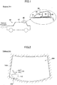
- an antenna unit 80 having a diversity structure that has a first antenna 81 and a second antenna 82 standing on a ground board 83 separated in a forward and backward direction of the vehicle 90 is mounted.
- the antennas 81, 82 are housed in a case 84.
- a glass antenna 100 has been proposed, in which one end for a first radiation pattern 121 is coupled to another end for a second radiation pattern 122 of differing length, arranged in a V-shaped pattern with respect to a vertical direction of a glass surface, and a grounded pattern 110 is arranged below the V-shaped pattern 120 (See Patent Document 2).
- a frequency switching type glass antenna for an automobile telephone for corresponding to a plurality of frequencies, for example, electric waves of resonance frequencies of 800 MHz and 1.5 GHz are transmitted and received.
- the glass antenna 100 is configured of two elements for a radiation pattern 120 (121, 122) and the grounded pattern 110, a wide space for arrangement is required.
- the glass antenna 100 is required to be arranged separated by a predetermined distance from the side edge part 710d and the defogger.
- the antenna becomes noticeable, and reduces appearance.
- a size of the defogger is required to be small, and a degree of freedom of design of the defogger is reduced.
- the present invention aims at providing a glass antenna and a vehicle window glass that improves appearance and can perform broadband communication.
- DE 199 23 036 A1 relates to a miniaturized planar antenna having a conducting patch which can be sealed and bonded to a dielectric plane such as a car window.
- the antenna has a broadband slot resonator with elements tuned for both D and E bands.
- WO 2014/129588 A1 relates to a vehicle window glass including a glass plate, a dielectric, a conductive film disposed between the glass plate and the dielectric, and an antenna comprising a pair of electrodes disposed opposite the conductive film across the dielectric, and is characterized in that: the conductive film includes a pair of opposed portions opposite the pair of electrodes across the dielectric, a main slot, and a pair of sub-slots; the main slot includes on one end an open end opened at an outer edge of the conductive film and is formed between the pair of opposed portions; and the pair of sub-slots each include on one end an open end opened at the outer edge of the conductive film, with one sub-slot connecting to the main slot in such a manner as to surround the pair of opposed portions, the other sub-slot connecting to the main slot at the other end in such a manner as to surround the other of the pair of opposed portions.
- US 2012/154229 A1 relates to a vehicle window glass having a glass plate, a conductive film laminated on the glass plate and an antenna structured with a feeding structure placed on the conductive film, and is characterized in that the feeding structure has a dielectric and a pair of electrodes, that the conductive film has a slot one end of which makes an upper edge of the conductive film an open end, and is disposed between the glass plate and the dielectric, and that the pair of electrodes are disposed on the opposite side of the side of the conductive film with the dielectric in between so that the slot is sandwiched between the pair of electrodes when the pair of electrodes are projected onto the conductive film, and are capacitively coupled to the conductive film.
- the problem relates to providing an alternative antenna layout enabling broadband communication.
- a glass antenna arranged on a vehicle window glass it becomes possible to improve appearance and to perform broadband communication.
- a direction refers to a direction on the drawings.
- drawings are drawings when viewed facing a surface of a window glass, and drawings may be viewed from the inside (or viewed from the outside) in a state that a window glass is mounted in the vehicle.
- a right-left direction (transverse direction) on the drawing corresponds to the horizontal direction
- an up-down direction corresponds to the vertical direction.
- the drawings may be referred to as drawings viewed from the outside.
- a window glass according to the present invention is mainly a rear glass mounted in a rear part of a vehicle, and a right-left direction on the drawing corresponds to a vehicle width direction.
- a direction, such as parallel, or orthogonal, or the like allows a deviation enough to keep the effect of the present invention.
- FIG. 3 is an overall plan view depicting a rear window glass in which a glass antenna 1 is arranged.
- the glass antenna 1 is an example of a vehicle antenna according to the embodiment, and functions as a communication glass antenna.
- a window glass is an example of a window plate covering an opening of a vehicle body.
- the window glass is a member having a plate shape.
- a material of the window glass is not limited to a glass, but may be a resin, a film or the like.
- a window glass 60 in the vehicle in the rear of the vehicle (also referred to as a vehicle window glass or a rear glass) is mounted on a chassis opening (also referred to as an opening or a window opening) formed of a vehicle chassis (a body or a vehicle body).
- An outer periphery 61 of the window glass 60 is indicated by a solid line in FIG. 3 .
- a vehicle chassis 70 (a vehicle body or a hatch back door made from a metal or partially from a resin, e.g. including a resin around the opening within a metallic frame) is provided with edge portions (body flanges) 71a, 71b, 71c and 71d forming the window opening of the vehicle (See dashed lines in FIG. 3 ).
- the window glass 60 is developed in a plane.
- a lower edge portion 71c contacting the vehicle chassis 70 is indicated as a curve.
- the lower edge portion 71c extends in the vehicle width direction, i.e. in an approximately horizontal direction.
- respective slots 21 to 24 of a comb-tooth slot 20, two-sided island shaped slots 18 (14, 15), and connection slots 19 (12, 13) (See FIG. 4 ) of the glass antenna 1, that are arranged approximately in parallel with the adjacent lower edge portion 71c, extend in the vehicle width direction, i.e. in the approximately horizontal direction.
- the glass antenna 1, illustrated in FIG. 3 that is a vehicle glass antenna, is formed incorporated on one surface (particularly on a vehicle interior surface) of the window plate (window glass), by printing, embedding, adhering or the like.
- the glass antenna 1 is configured by arranging a rectangular metallic film 30 that is a conductor in which a cutout portion 10 is formed (e.g. a conductive film formed by baking a silver paste or the like) on the vehicle window glass (rear glass) 60.
- the conductive film of the present invention is not limited to a metallic film, and may be, for example, a conductive resin film.
- the metallic film 30 is cut out into an elongated hole (making a slit), and radiation is performed from the cutout part as a slot.
- the glass antenna 1 functions as a slot antenna.
- a black or brown shielding film (shielding part) 65 is formed in a periphery region on the surface of the window glass 60.
- an entire antenna 1 is arranged on the shielding film 65.
- a part of the antenna 1 may be arranged.
- the shielding film 65 includes a ceramic film such as a black ceramic film.
- FIG. 3 as a drawing viewed from inside, when the metallic film 30 forming a slot antenna is attached on a surface of the window glass 60 inside the vehicle, all elements of the glass antenna 1 are arranged on the window glass 60 inside the vehicle. Furthermore, with respect to the glass antenna 1, a part in which at least a resistor 8 and a coaxial cable 8c (See FIG. 5 ) are installed, or the entire glass antenna 1, is arranged within a region of the shielding film 65.
- the window glass is excellent in design.
- the shielding film 65 may be formed with shielding dot parts in a portion off the vehicle chassis 70 so that the shielding gradually becomes thinner approaching the center of the window (with a gradation).
- a defogger 40 having a plurality of heater wires 42 which are parallel to each other and a plurality of belt-like bus bars 41 which supply power to the heater wires 42 may be arranged.
- the heater wires 42 and the bus bars 41 that configure the defogger 40 are electrically heating type conducting patterns.
- the glass antenna 1 is arranged in the window glass 60 below the defogger 40, i.e. in a margin region between the lowermost heater wire 42c of the defogger 40 and a lower edge portion 71c of the opening of the vehicle chassis 70.
- a metallic part of the rear support part may project upward relative to the lower edge portion 71c of the opening of the vehicle chassis 70, and may be arranged in proximity to the glass antenna.
- the glass antenna is affected more from the metallic part of the rear support part than the lower edge portion 71c of the opening of the vehicle chassis 70.
- the glass antenna 1 in the case of attaching a glass antenna 1 to a vehicle with a configuration that is liable to be affected by the metallic part of the rear support part, in the margin region between the lowermost heater wire 42c and the lower edge portion 71c, the glass antenna 1 can be arranged at a position that is above the position illustrated in FIG. 3 , and adjacent to the lowermost heater wire 42c or at a position close to the center.
- the glass antenna 1 is arranged, for example, at either a corner portion between the lower edge portion 71c of the opening of a vehicle chassis 70 and a side edge portion 71b continuing into the lower edge portion 71c (a part indicated by a solid line in the lower right position in FIG. 3 ), or near a corner portion between the lower edge portion 71c and a side edge portion 71d continuing into the lower edge portion 71c (a part indicated by a dotted line in the lower left position in FIG. 3 ).
- the glass antenna 1 may be arranged adjacent to either of the left and right corner portions of the upper edge portion 71a of the vehicle chassis 70. In this case, the configuration is flipped top-bottom.
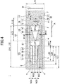
- FIG. 4 is an enlarged view depicting a glass antenna according to a first embodiment arranged on a vehicle window glass 60.
- a power supply slot 11 a connection slot 19, a root slot 27, a comb-tooth slot 20 and a two-sided island shaped slot 18 are formed as cutout portions 10.
- a pair of power supply units (power supply points) 7 are arranged so as to straddle the power supply slot 11.
- the power supply slot 11, on which the pair of power supply units 7 are arranged so as to straddle the power supply slot 11, extends in an approximately up- down direction (direction "B") as a first direction.
- connection slot 19 extends in an approximately horizontal direction (direction "A") as a second direction that is different from the first direction, and connects the power supply slot 11 and the root slot 27.
- connection slot 19 is provided with a line-shaped linear connection slot 12 having a constant slot width connected to the power supply slot 11 at an end portion g (connection point g), and a triangular slot (triangle shaped slot) 13 arranged between the linear connection slot 12 and the root slot 27.
- the linear connection slot 12 extends in an approximately horizontal direction (fourth direction).
- the triangular slot 13 has a shape of an isosceles triangle, in which a slot width on the side (end portion f) connected to the linear connection slot 12 is great, and the slot width gradually becomes smaller extending toward the root slot 27 (end portion e).
- the comb-tooth slot 20 and the root slot 27 have shapes of a head portion of a fork, particularly a digging fork.
- the comb-tooth slot 20, having a shape of tip sections (claw sections or tooth sections) from the head portion of a fork, has a plurality of linear slots (tip slots) respectively extending parallel to each other in an approximately horizontal direction (direction "A").
- the comb-tooth slot 20 is provided with a linear first slot 21, a linear second slot 22, a linear third slot 23 and a linear fourth slot 24.
- An end of the first slot 21 is a lower part comb-tooth slot (lower part tip slot) connected to a lower end of the root slot 27, and an end of the fourth slot 24 is an upper part comb-tooth slot (upper part tip slot) connected to an upper end of the root slot 27.
- the second slot 22 and the third slot 23 are central part comb-tooth slots (central part tip slots).
- the first slot 21 extends up to an end portion "a"
- the second slot 22 extends up to an end portion "b”
- the third slot 23 extends up to an end portion "c”
- the fourth slot 24 extends up to an end portion "d”.
- the slot lengths of the respective slots in the comb-tooth slot 20 are denoted by L21, L22, L23 and L24, respectively, in FIG. 4
- the slot lengths satisfy a relation L21 > L23 > L24 > L22.
- the first slot 21 having the greatest slot length L21 is arranged in the lowest portion (close to the lower end portion 71c).
- the island shaped slots 14, 15 are arranged so that the connection slot 19, the root slot 27 and the comb-tooth slot 20 are interposed in the vertical direction from both sides.
- FIG. 4 illustrates an example in which the island shaped slots 14, 15 have the same length. The lengths of the island shaped slots 14, 15 on the upper and lower sides may be different from each other.
- a corner of the slot may be a curve having a curvature.
- the end portion may be a terminal end of an extension of the slot, or may be a neighborhood of the terminal end before the end portion of the slot.
- the approximately upward direction means locating relatively above other end portions, and includes upward in the vertical direction and obliquely upward.
- the approximately downward direction means locating below other end portions, and includes downward in the vertical direction and obliquely downward.
- a mounting angle of the window glass 60 with respect to the vehicle falls, for example, preferably within a range of 15° to 90° with respect to a horizon plane.
- the up-down direction of the glass antenna is an up-down direction on a surface of the window glass, and have the same inclination as that of the window glass.
- the respective slots 21, 22, 23 and 24 of the comb-tooth slot 20 are arranged approximately parallel to the adjacent lower edge portion 71c.
- a longitudinal length of a space for arranging the metallic film 30 to be formed can be set small. Even if a defogger 40 occupies most of the window glass (rear glass) 60 in the up-down direction, the glass antenna 1 that is small in the up-down direction can be arranged in a small margin region of the window glass 60.
- FIG. 3 illustrates an example in which the glass antenna 1 is arranged adjacent to a lower right corner portion of the window glass 60.
- the glass antenna 1 may be arranged in the lower left portion. In this case, the configuration is flipped horizontally.
- the glass antenna 1 may be arranged adjacent to the upper edge portion 71a of the vehicle chassis 70.
- the power supply slot 11 that extends in an approximately up-down direction has an opening upward and an opening downward.
- a part closer to the side edge portion 71b of the vehicle chassis 70, which is arranged adjacent to the metallic film 30, than the power supply slot 11 (right side in FIG. 4 ) functions as a ground side conductive body 31, and a part (left side) farther from the side edge portion 71b than the power supply slot 11 functions as a core wire side conductive body 32.
- the pair of power supply units 7 supply power to the ground side conductive body 31 and the core wire side conductive body 32 at a position arranged so as to straddle the power supply slot 11.
- the power supply unit 7 is arranged below a portion at which the power supply slot 11 is connected to the linear connection slot 12 and is arranged in the lower part of the metallic film 30.
- the core wire side conductive body 32 of the metallic film 30 is provided with a solid part with a great width (solid-fill part).
- solid-fill part a solid part with a great width
- the above-described island shaped slots 14, 15 are arranged on both sides so that the width of the metallic film 30 can be increased while maintaining the formability of glass.
- the island shaped slots 14, 15 on both sides are also used for controlling the frequency used for communication.
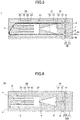
- FIG. 5 is an enlarged view illustrating a glass antenna obtained by arranging a resistor 9; and an on-glass connector for connecting coaxial cable 8 (in the following, simply referred to as a "connector") connected to a coaxial cable 8c at the power supply unit 7.
- the ground side conductive body 31, the core wire side conductive body 32, the power supply unit 7, the resistor 9, the coaxial cable 8c and the on-glass connector for connecting coaxial cable 8 are arranged on one surface (the same surface) of the window glass 60 that is a conductive body, i.e. an indoor side surface.
- the on-glass connector for connecting coaxial cable 8 is soldered with a solder 8s to the power supply unit 7 arranged so as to straddle the power supply slot 11.
- an internal conductive body of the coaxial cable 8c is connected to and soldered to the core wire side conductive body 32.
- An external conductive body of the coaxial cable 8c, such as a braided wire, is connected to and soldered to the ground side conductive body 31.
- the resistor 9 for detecting connection may be arranged.
- the ground side conductive body 31 and the core wire side conductive body 32 of the metallic film 30 form a closed circuit with a route that includes the resistor 9.
- the circuit is connected inside (internal conductive body) and outside (external conductive body such as the braided wire) of the coaxial cable 8c, which are connected to the connector 8 arranged at the power supply unit 7.
- a member indicated by X in FIG. 5 can function as a disconnection detection path for detecting a breakage of the vehicle window glass 60.
- the ground side conductive body 31 and the core wire side conductive body 32 are metallic films that were formed by printing a paste including a conductive metal, such as a silver paste, on the vehicle interior surface of the window glass 60, and baking the paste.
- a conductive metal such as a silver paste
- the formation method is not limited to the above, a linear body or a foil-like body made of a conductive material such as copper may be formed on one surface of either of the vehicle interior surface or the vehicle exterior surface of the window glass.
- the conductive bodies may be formed by pasting on the window glass with an adhesive agent. In the case where the window glass is a laminated glass, the conductive bodies may be formed inside the window glass.
- the window glass 60 is a rear glass, and typically a strengthened glass is used, when the window glass is broken, the window glass becomes fine granular fragments.
- the core wire side conductive body 32 and the ground side conductive body 31 in the state of silver paste printed on the window glass 60 also become granular fragments and are broken.
- the disconnection detection path X is formed by connecting the core wire side conductive body 32 and the ground side conductive body 31 with the connector 8 connected to the power supply unit 7 and with the resistor 9, when a disconnection occurs in the disconnection detection path X, the value of resistance becomes infinity, and thereby a breakage of the window glass 6 can be detected.
- the antenna according to the embodiment can detect a breakage of a glass by detecting a disconnection, it is not necessary to separately arrange a glass breakage detection means on the window glass 60. Because a number of parts arranged on the window glass can be reduced, a space for arranging an antenna and a glass breakage detection means can be reduced, and the appearance of the window glass is improved.
- the power supply unit 7 and the resistor 9 are proximally arranged across the connection point g to the linear connection slot 12.
- the on-glass connector for connecting coaxial cable 8 arranged at the power supply unit 7 and the resistor 9 may be integrated, and modularized.
- a mounting performance for arranging members is enhanced.
- the vehicle chassis is made of a metal
- a radiating element of a linear antenna in a silver paste state is arranged at a position near the vehicle chassis or a position close to a defogger (related art, see FIG. 2 )
- a reception gain for an antenna tends to be reduced.
- the radiating element is a slot antenna; thus, an electric field, made by an electric current flowing inside the metallic film 30 forming slots, is formed in a closed form.
- the antenna according to the embodiment is not liable to be affected by the interference with a metal or a resin around the antenna.
- the antenna according to the embodiment even if a metal, such as a defogger, a vehicle chassis or a rear support part, is in proximity around the antenna, or even if a resin part of the vehicle chassis is in proximity around the antenna, a stable characteristic can be obtained. Furthermore, even if a metallic film such as a transparent conductive film is formed around the antenna, an antenna that is not liable to be affected by interference can be formed in the same way as above.
- Frequencies used for communication as specified by countries are different from each other. Even within one country, frequency bands used for respective carriers are different from each other. An antenna for accommodating a wide band so that a plurality of communication waves can be received is preferable.
- the glass antenna according to the present invention is set to perform communication in, for example, three bands, 0.698 GHz to 0.96 GHz (Band 1), 1.71 GHz to 2.17 GHz (Band 2) and 2.4 GHz to 2.69 GHz (Band 3), among the bands used for LTE (Long Term Evolution).
- the glass antenna according to the present invention is set to perform communication in an ISM (Industry Science Medical) band, as a frequency band used for communication.
- the ISM band used for communication includes 0.863 GHz to 0.870 GHz (Europe), 0.902 GHz to 0.928 GHz (US) and 2.4 GHz to 2.5 GHz (common worldwide).
- a communication standard using the 2.4 GHz band that is an example of the ISM band includes a wireless LAN of the DSSS method in compliance with IEEE 802.11b, Bluetooth (trademark registered), a part of FWA system and the like.
- the glass antenna according to the embodiment also can be applied to the ISM bands for communication.
- a slot antenna by forming a power supply slot 11, a connection slot 19 (12, 13), a root slot 27, a comb-tooth slot 20, and an island shaped slot 18 (14, 15) in the metallic film 30, a plurality of frequencies are accommodated.
- a plurality of slots with different length and different widths are formed, and the antenna can accommodate a wide frequency band.
- the vertically polarized wave tends to be emphasized.
- the respective slots 21 to 24 of the comb-tooth slot, the connection slot 19 (12, 13), and two-sided island shaped slots 18 (14, 15) extend in approximately horizontal directions. From a horizontal slot antenna, vertically polarized radio waves can be transmitted and received.
- the respective slots are caused to extend in an approximately horizontal direction; moreover, in the low frequency region, mainly vertical polarized waves are accommodated.
- the antenna can accommodate a horizontal polarized wave.
- the glass antenna according to the embodiment of the present invention without affecting a design of the vehicle or an aerodynamic characteristic, as in the related art illustrated in FIG. 1 , and without deteriorating an appearance because the antenna is arranged near the outer periphery 61 of the window glass 60, can accommodate a plurality of bands and a wide frequency band. Accommodating the wide frequency band according to the embodiment will be described in detail in a practical example 1 with reference to FIGS. 11 to 20 .
- FIG. 6 is an enlarged view depicting a glass antenna 1A according to a second embodiment.
- the two-sided island shaped slots 18 (14, 15) are not arranged.
- FIG. 6 illustrates an example of a configuration in which a length in the longitudinal direction is almost the same as the length in the longitudinal direction of the configuration illustrated in FIG. 4 .
- the island shaped slots 18 (14, 15) on the upper side and the lower side are not arranged, and a length in the longitudinal direction of the space for arranging the glass antenna 1A can be further reduced. Even if a defogger 40 occupies most of the window glass (rear glass) 60 in the up-down direction the glass antenna 1 that is small in the up-down direction can be arranged in a further small margin region of the window glass 60.
- the second embodiment it is impossible to have a minimum value for a return loss at the frequency of 0.7525 GHz where the impedance matching was performed by the island shaped slots 14, 15 in the first embodiment.
- a return loss in the Band 1 in the first embodiment is more excellent than a return loss in the second embodiment.
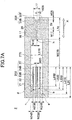
- FIG. 7A is an enlarged view depicting a glass antenna 2 according to a third embodiment.
- the third embodiment is different from the first and second embodiments in that a power supply slot 16 is directly connected to a root slot 27B, and a first direction where the power supply slot 16 extends is an approximately horizontal direction.
- the power supply slot 16 extending in an approximately horizontal direction opens in the approximately horizontal direction (right side in FIG. 7A ).
- a linear slot 25, which is one of the slots of the comb-tooth slots 20B and a comb-tooth part connected to the root slot 27B that is a root part, is an open-end slot.
- One end of the linear slot 25 opens in an approximately horizontal direction (left side in FIG. 7A ).
- FIG. 7B is an enlarged view illustrating a glass antenna obtained by arranging a resistor 9 and a power supply unit 7 in the glass antenna for communication according to the third embodiment illustrated in FIG. 7A .
- a part closer to the lower edge portion 71c, where the glass antenna 2 is arranged adjacent to the lower edge portion 71c, than the power supply slot 16 functions as a core wire side conductive body 32B, and a part farther from the lower edge portion 71c than the power supply slot 16 functions as a ground side conductive body 31B.
- a pair of power supply units 7 are arranged so as to straddle the power supply slot 16.
- the pair of power supply units 7B supply power to the ground side conductive body 31B and the core wire side conductive body 32B.
- a notch portion 28 is arranged so as to contact the power supply slot 16.
- a notch portion 29 is arranged so as to contact the power supply slot 16. Note that FIG. 7A and FIG. 7B depict an example where sizes of the notch portions 28 and 29 are the same. The sizes may be different from each other.
- the part near the lower edge portion 71c is set to be the core wire side conductive body 32B, and the part far from the lower edge portion 71c is set to be the ground side conductive body 31B. Because the sizes of the conductive bodies are almost the same, an opposite assignment is possible. That is, in the third embodiment, an upper part and a lower part of the metallic film 30 function as one of the core wire side conductive body and the ground side conductive body and as the other conductive body, respectively. The function of the conductive body can be appropriately selected according to a direction of arranging the coaxial cable.
- the pair consisting of power supply unit 7 and the resistor 9 are arranged adjacent to each other in an approximately horizontal direction.
- a division slot 17 extending in a direction approximately orthogonal to the power supply slot 16 extending in the horizontal direction may be arranged between the power supply unit 7 and the resistor 9 so as not to connect the power supply unit 7 and the resistor 9 directly.
- the coaxial cable of the power supply unit is arranged in the vertical direction.
- the embodiment can be appropriately selected according to the arrangement direction of cable.
- the glass antenna 2 because the respective linear slots 21B to 24B of the comb-tooth slot 20B and the power supply slot 16 extend in approximately horizontal directions, a length in the longitudinal direction of the space for arranging the metallic film 30B to be formed can be reduced. Even if a defogger 40 occupies most of the window glass (rear glass) 60 in the up-down direction, the glass antenna 1 that is small in the up-down direction can be arranged in a further small margin region of the window glass 60.
- FIG. 8 is an enlarged view depicting a glass antenna 3 according to a fourth embodiment.
- the root slot and the comb-tooth slot configured the shape of a head portion of a digging fork.
- the tip portion of the head four comb-tooth slots 20 were arranged, but the number of comb-tooth slots 20C may be three.
- FIG. 8 illustrates an example in which the comb-tooth slot 20C projected from a root slot 27C and extending in an approximately horizontal direction is provided with three slots 21C, 22C and 23C that are tip portions.
- a power supply slot 16C and the root slot 27C are directly connected to each other, and a first direction where the power supply slot 16C extends is an approximately horizontal direction.
- slot widths of the slots 21C, 22C and 23C that are tip portions having linear shapes are greater than the slot widths of the slots 21, 22, 23 and 24 in the first to third embodiments, and length of the slots 21C, 22C and 23C are shorter than those of the slots 21, 22, 23 and 24.
- the fourth embodiment can be applied to the case where there is enough space for arranging the antenna both in the vertical direction and in the horizontal direction.
- an opening portion is not formed in a metallic film 30C
- a cutout portion does not contact an edge portion of the metallic film 30C, and an electric field generated by an electric current inside the metallic film 30C forming slots is formed in a closed loop.
- the glass antenna 3 is not likely to be affected by an interference with a metal around the glass antenna 3. It becomes possible to make the distance from the edge portions 71c, 71b of the vehicle chassis 70 to the glass antenna 3 according to the embodiment further smaller. Because the size of space for arranging the antenna and the distance from the vehicle chassis vary depending on vehicles, the configuration is appropriately selected.
- the power supply unit 7 is arranged in the lower part of the metallic film 30.
- a rear support part (interior material) of a backseat banks upward, at the stage of assembling the vehicle, it is difficult to arrange a connector in the lower part inside the conductive film.
- the power supply unit 7 is more affected from the metallic part of the rear support part than from the lower edge portion 71c.
- a configuration of arranging a connector in an upper part inside the conductive film is preferable.
- a fifth embodiment and a sixth embodiment will be described in the following.
- FIG. 9A is an enlarged view depicting a glass antenna 4 according to a fifth embodiment.
- the glass antenna 4 according to the fifth embodiment is different from the glass antenna 1A according to the second embodiment illustrated in FIG. 6 in that the comb-tooth slot is provided with six linear slots, a part of the core wire side conductive body 32D is cutout and the position of the power supply unit 7D is different.
- the comb-tooth slot 20D is provided with a first slot 21D, a second slot 22D, a third slot 23D, a fourth slot 24D, a fifth slot 25D and a sixth slot 26 that are tip portions having linear shapes. Slot lengths of the first slot 21D, the second slot 22D, the third slot 23D, the fourth slot 24D, the fifth slot 25D and the sixth slot 26 are different from each other.
- the slot lengths of the six linear slots are different from each other. Furthermore, a greater number of linear slots are arranged than the first embodiment, i.e. four linear slots. Because the number of slots extending in an approximately horizontal direction is great, with respect to important vertically polarized waves, an excellent broadband communication can be performed without arranging island shaped slots.
- FIG. 9B is an enlarged view depicting a glass antenna obtained by arranging a resistor 9D, and arranging a connector 8D connected to a coaxial cable 8cD at the power supply unit 7 on the glass antenna 4 illustrated in FIG. 9A .
- a part closer to the side edge portion 71B of the vehicle chassis 70, where the glass antenna 4 is arranged adjacent to the side edge portion 71B, than the power supply slot 11D functions as a ground side conductive body 31D, and a part farther from the side edge portion 71b than the power supply slot 11 (left part in FIG. 9B ) functions as a core wire side conductive body 32D.
- the power supply unit 7D to which the connector 8D is soldered with a solder 8sD, is located below a part at which the linear connection slot 12D is connected to the power supply slot 11D.
- a notch portion 28D is arranged so as to contact the power supply slot 11D.
- the resistor 9D is arranged and the connector 8D connected to the coaxial cable 8cD is arranged at the power supply unit 7 in the glass antenna 4.
- a notch portion 28D is close to a site, at which the coaxial cable 8cD is arranged (power supply unit 7D), and is cut from up above the power supply slot 11D extending in an approximately vertical direction, so as not to be connected to the linear connection slot 12D.
- the notch portion 28D is cut from up above, the notch portion 28D need not include an upper edge of the core wire side conductive body 32D, as long as the notch portion 28D is connected to the power supply slot 11D.
- the notch portion may be formed leaving the upper edge of the core wire side conductive body 32D as a linear element.
- the vehicle is a movable body
- the vehicle is preferably provided with a plurality of communication antennas and is able to select a radio wave by switching to an antenna with higher receiving sensitivity depending on a location.
- a MIMO (Multiple-Input Multiple-Output) configuration that increases a communication capacity by a plurality of antennas is further preferable.
- a wide band antenna having the same configuration as the antenna 1 according to the embodiment may additionally be arranged at a position approximately symmetric to the antenna 1 with respect to a center line extending in the width direction of the window glass 60.
- the plurality of antennas are preferably arranged separated by a predetermined distance (e.g. greater than or equal to 0.2 times a wavelength of an electric wave with a frequency of 0.7 GHz, i.e. 86 mm).
- two glass antennas 1 having a left-right symmetric configuration may be arranged.
- two antennas may be arranged combining with the antenna according to the other embodiment.
- a configuration of a glass antenna which is preferably used combining with the glass antenna according to any one of the first to fifth embodiments, on the premise that the glass antenna is arranged at the lower left position indicated by a dotted line in FIG. 3 for the purpose of improving the reception condition in the ISM frequency band, will be described.
- FIG. 10A is an enlarged view depicting a glass antenna according to the sixth embodiment.
- the glass antenna according to the sixth embodiment is different from the glass antenna 1A according to the second embodiment illustrated in FIG. 6 , in that two linear slots are arranged in the comb-tooth slot 20E, a part of the ground side conductive body 31E is extended, and a position of the power supply unit 7E is different.
- the comb-tooth slot 20E is provided with a first slot 21E and a second slot 22E both having a linear shape. An end portion of the first slot 21E is connected to a lower end of the root slot 27E that extends in an approximately vertical direction, and an end portion of the second slot 22E is connected to an upper end of the root slot 27E.
- the comb-tooth slot 20E is not provided with a central part comb-tooth slot.
- the first slot 21E is a lower part comb-tooth slot and the second slot 22E is an upper part comb-tooth slot.
- slot lengths of two linear slots 21E, 22E arranged in an upper part and a lower part, respectively, are different from each other.
- the glass antenna according to the embodiment is intended to transmit/receive ISM electric waves within a band that is narrower than for the LTE, and the ISM band can be covered precisely. The feature will be described later in detail (in Example 8).
- FIG. 10B is an enlarged view depicting an antenna obtained by arranging a resistor 9E, a connector 8E connected to a coaxial cable 8cE at a power supply unit 7E with respect to the glass antenna 5 illustrated in FIG. 10A .
- a part closer to the side edge portion 71b of the vehicle chassis 70, which is arranged adjacent to the glass antenna 5, than the power supply slot 11 (right side in FIG. 10B ) functions as a ground side conductive body 31E, and a part (left side) farther from the side edge portion 71b than the power supply slot 11 functions as a core wire side conductive body 32E.
- the power supply unit 7E, to which the connector 8E is soldered with a solder 8sE, is located above a part at which the linear connection slot 12E is connected to the power supply slot 11E.
- a part in which the resistor 9E is arranged is formed to be greater than the other parts. That is, an extension part 33 is arranged.
- the ground side conductive body 31E has a shape in which the part in which the resistor 9E is arranged is extended to be greater than a portion in which the connector 8E is arranged that is another region. In this way, by arranging the extension part 33, it becomes possible to adjust a resonance frequency while controlling interference from the resistor 9E.
- FIGS. 10A and 10B illustrate an example in which the extension part 33 is arranged in an approximately lower half of the ground side conductive body.
- the part in which the resistor 9E is arranged may be extended only partially.
- the ground side conductive body 31E may not be expanded, and only a part around the part in which the resistor 9E is arranged may project.
- the antenna that receives an electric wave in the ISM band has been described.
- An antenna for another use may be arranged on the rear glass.
- an antenna for a different use than the antenna according to the embodiment i.e. other than LTE, ISM, for example an antenna for receiving broadcasting waves (TV, AM, FM, DTV, DAB, or the like) may be arranged on the rear glass.
- an antenna for remote keyless entry or an antenna for smart entry that locks and unlocks vehicle doors may be arranged on the rear glass.
- the glass antenna for different use is preferably arranged at a location separated from the glass antenna according to the present invention on the window glass.
- the glass antenna for different use is preferably arranged near the upper edge portion.
- the antenna for different use is preferably arranged near the lower edge portion.
- the glass antenna is configured by arranging on the window glass (rear glass) 60 for vehicle a metallic film (conductive film) that is a conductive body (e.g. a copper foil or a silver foil) in which the cutout portion 10 is formed by punching or etching.
- the glass antenna according to the present invention can be configured by printing using a screen plate in the same way as a conventional glass antenna or a defogger that is formed by burning a silver paste. In this case, the glass antenna according to the present invention can be formed collectively with another glass antenna or a defogger, and is excellent in mass productivity.
- the glass antenna may be formed by arranging (attaching), at a predetermined location on a vehicle interior surface or a vehicle exterior surface of a window glass, a synthetic resin film, a flexible circuit substrate or the like in which or on which a conductive layer including the above-described cutout portion is arranged.
- the above-described cutout portion may be formed in a part of the thin film of the metallic layer so that the metallic layer functions as a glass antenna.
- the glass antenna and the window glass have been described by the plurality of embodiments.
- the present invention is not limited to the embodiments.
- Various variations and improvements, such as combination/replacement with/by a part or a whole of another embodiment may be made without departing from the scope of the present invention.
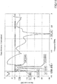
- FIG. 11 is a diagram depicting a graph showing a return loss including a minimum value obtained by a simulation for the glass antenna according to the first embodiment.
- FIG. 11 depicts an example of a graph obtained by performing a simulation for a glass antenna 1 arranged on a simple glass that is the same as the rear glass, separately from the vehicle.
- a return loss was numerically calculated for a frequency within a range of 0.5 GHz to 3.0 GHz.
- the return loss is preferably -7 dB or less, and more preferably -10 dB or less.
- the power supply unit 7 (connector 8) was arranged in the power supply slot 11 near almost a center between a lower end of the power supply slot 11 and a connection point g where the power supply slot 11 is connected to the linear connection slot 12.
- the resistor 9 was arranged in the power supply slot near almost a center between an upper end of the power supply slot and the connection point g.
- the glass antenna 1 according to the present invention is set to have a minimum value (bottom value) for a specific frequency in the frequency band used for communication.
- a frequency band within a range from 0.698 GHz to 0.96 GHz will be referred to as Band 1
- a frequency band within a range from 1.71 GHz to 2.17 GHz will be referred to as Band 2
- a frequency band within a range from 2.4 GHz to 2.69 GHz will be referred to as Band 3.
- FIG. 12 is a diagram schematically illustrating an electric current distribution in the case where the return loss has a minimum value at a frequency of 0.698 GHz.
- the frequency is 0.698 GHz
- FIG. 13 is a diagram schematically illustrating an electric current distribution in the case where the return loss has a minimum value at a frequency of 0.7525 GHz.
- the frequency is 0.7525 GHz
- the lower island shaped slot 15 resonates, and thereby an electric current flows in a periphery of the island shaped slot 15, to radiate an electro-magnetic field.
- FIG. 14 is a diagram schematically illustrating an electric current distribution in the case where the return loss has a minimum value at a frequency of 0.8125 GHz.
- the third slot 23, which is the second longest slot and arranged at around a center in the comb-tooth slot 20, resonates, and thereby an electric current flows in a periphery of the third slot 23, to radiate an electro-magnetic field.
- FIG. 15 is a diagram schematically illustrating an electric current distribution in the case where the return loss has a minimum value at a frequency of 0.8825 GHz.
- the fourth slot 24 which is the third longest slot and arranged at the highest portion in the comb-tooth slot 20, resonates, and thereby an electric current flows in a periphery of the fourth slot 24 and in a lower periphery and an upper periphery of the triangular slot 13, to radiate an electro-magnetic field.
- FIG. 16 is a diagram schematically illustrating an electric current distribution in the case where the frequency is 0.945 GHz and 0.96 GHz.
- the second slot 22 which is the shortest slot and arranged at around the center in the comb-tooth slot 20, resonates, and thereby an electric current flows in a periphery of the second slot 22, to radiate an electro-magnetic field.
- a wavelength of an electric wave in the air at a central frequency in the frequency band is ⁇
- a wavelength contraction rate is k
- Band 1 in the above example, 0.698 GHz, 0.8125 GHz, 0.8825 GHz and 0.945 GHz
- slot lengths of the first slot 21, the second slot 22, the third slot 23 and the fourth slot 24 are set to fall within a range of 1/6 ⁇ g to 1/3 ⁇ g , and thereby an impedance matching can be performed.
- a slot length of the island shaped slot 15 is set to fall within a range of 0.4 ⁇ g to 0.6 ⁇ g at a predetermined single frequency in the frequency band of Band 1 (in the above example, 0.7525 GHz), and thereby an impedance matching can be performed.
- FIG. 17 is a diagram schematically depicting an electric current distribution in the case where the frequency is 1.71 GHz (Band 2).
- the frequency is 1.71 GHz
- an electric current flows in the power supply slot 11, to radiate an electro-magnetic field.
- FIG. 18 is a diagram schematically depicting an electric current distribution in the case where the frequency is 2.17 GHz (Band 2).
- the frequency is 2.17 GHz
- a great electric current flows in the power supply slot 11
- small electric currents flow in the upper and lower island shaped slots 14, 15, to radiate an electro-magnetic field.
- FIG. 19 is a diagram schematically illustrating an electric current distribution in the case where the return loss has a minimum value at a frequency of 2.2 GHz.
- the frequency is 2.2 GHz
- a great electric current flows in the power supply slot 11, and an electric current flows in the upper island shaped slot 14, to radiate an electro-magnetic field. Note that this frequency is excluded from the desired frequency band according to the present invention.
- FIG. 20 is a diagram schematically depicting an electric current distribution in the case where the frequency is 2.4 GHz and 2.69 GHz (Band 3).
- the frequency is in Band 3
- a great electric current flows in the power supply slot 11, to radiate an electro-magnetic field.
- a plurality of slots with different length and different widths are formed in the glass antenna 1 according to the embodiment, and the glass antenna 1 can correspond to a wide frequency band.
- the dimensions of the glass antenna according to Second Example are set to be the same as in First Example.
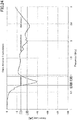
- FIG. 21 is a diagram depicting a graph showing a return loss (results of simulation) in the case where the arrangement position of the power supply unit 7 is changed in the glass antenna according to the first embodiment, illustrated in FIG. 4 , in the frequency band used for communication.
- D f represents a position of the power supply unit 7, where the center of the metallic film 30 in the vertical direction is set to 0 mm (located 25 mm from the outer edge).
- the value of D f varies, i.e. 12.5 mm, 13 mm, 13.5 mm, 14 mm, 14.5 mm, 15 mm, 15.5 mm, 16 mm and 16.5 mm.
- the return loss is less than or equal to -7 dB.
- the performance of the antenna is maintained.
- FIG. 22 is a diagram depicting a graph showing a return loss in the glass antenna 2 according to the third embodiment obtained by simulation.
- the dimensions in the shape of the glass antenna 2 illustrated in FIG. 7A were as follows (in units of mm):
- the size of the notch portion 29 was made to be the same as the notch portion 28.
- the return loss in the desired frequency bands, Band 1 to Band 3 was about less than or equal to -7 dB, and a desired antenna performance can be obtained in the desired frequency band.
- FIG. 23 is a diagram depicting a graph showing a return loss obtained by simulation for the glass antenna 3 according to the fourth embodiment.
- the dimensions in the shape of the glass antenna 3 illustrated in FIG. 23 were as follows (in units of mm):
- the respective wide slots 21C, 22C, and 23C of the glass antenna 3 influence one another, to radiate an electro-magnetic field, and thereby satisfactory impedance matching can be performed in the specific frequency band.
- the return loss in the desired frequency bands, Band 1 to Band 3 was about less than or equal to -7 dB, and a desired antenna performance can be obtained in the desired frequency band.
- FIG. 24 is a diagram depicting a graph showing a return loss by actual measurement in the glass antenna according to the first embodiment.
- the return loss shown in FIGS. 16 , 22 and 23 were the results of simulation for the configuration in which a glass antenna was arranged on a glass plate representing a simple glass, separately from a vehicle.
- a window glass 60 was mounted in an actual vehicle chassis 70, the glass antenna 1 was arranged on the window glass 60, and the return loss was measured.
- the dimensions of the glass antenna 1 were made to be the same as the first example.
- the position where the glass antenna 1 was arranged on the window glass 60 was determined as follows: a distance from the lower edge portion 71c of the vehicle chassis 70 to a lower edge of the metallic film 30 was 4 mm, and a distance from a side edge portion 71b of the vehicle chassis 70 to a side edge of the metallic film 30 was 58.9 mm.
- the antenna performance in Band 1 to Band 3 for the desired frequency bands is approximately less than or equal to -7 dB, and approximately satisfies the requirement to return loss in the desired frequency bands.
- a wavelength of an electric wave in the air at a central frequency in the frequency band is ⁇
- a wavelength contraction rate is k
- slot lengths L21, L22, L23 and L24 of the respective slots 21, 22, 23 and 24 of the dimensions of the glass antenna 1 used in the second example correspond to a range of 0.21 ⁇ g to 0.23 ⁇ g , and are thus set to fall within a range from 1/6 ⁇ g to 1/3 ⁇ g .
- a particularly excellent impedance matching is performed.
- slot lengths L14, L15 of the island shaped slots 14, 15 correspond to 0.47 ⁇ g , and are thus set to fall within a range of 0.4 ⁇ g to 0.6 ⁇ g .
- a particularly excellent impedance matching is performed.
- FIG. 25 is a diagram schematically illustrating a condition for measurement, and depicting a status of a vehicle 50 and a transmission antenna Tx used in the measurement.
- the antenna gain was actually measured for a vehicle window glass, on which a glass antenna is formed, assembled into a window frame of a vehicle on a turntable. At this time, the window glass was inclined at an angle of about 20° with respect to the horizontal plane.
- the measurement was performed by setting left-right, fore-aft wheel axis centers of the vehicle 50, to which the vehicle window glass with the glass antenna was assembled, to a center of the turntable, and by rotating the vehicle in the horizontal direction by an angle ⁇ r up to 360°.
- An antenna gain was measured within a predetermined frequency range every 10 MHz for frequency, every 2 degrees for turntable rotating angle ⁇ r from 0° to 360°, and every 2 degrees for transmission elevation angle ⁇ e from 0° to 30°.
- the antenna gain was indicated with an absolute gain by calibrating in advance the measurement system using a standard gain antenna.
- FIG. 26 shows a gain when a vertically polarized wave from the transmission antenna Tx was received by the glass antenna 1 (results of measurement for gain averaged over all rotational angles (whole circumferential) and all elevation angles).
- FIG. 27 shows a gain when a horizontally polarized wave from the transmission antenna Tx was received by the glass antenna 1. More specifically, the gain was measured for each elevation angle ⁇ e of the transmission antenna Tx, i.e. every 2° from 0° to 30°, rotating the vehicle 50 in the horizontal direction by ⁇ r up to 360° (every 2° from 0° to 360° (whole circumferential)), and averaging the measured data with respect to the rotating angle ⁇ r and the elevation angle ⁇ e .
- the resistor 9 a resistor of a resistance value of 100 k ⁇ with an error of ⁇ 5% (resistor module element) was used. Moreover, for the power supply unit 7, the on-glass connector for connecting coaxial cable 8 was used by soldering the connector.
- TABLE 1 shows average gains for vertically polarized waves received by the glass antenna 1 for communication waves in the three bands, as shown in FIG. 26 , among the bands used as the LTE, i.e. 0.698 GHz to 0.96 GHz (Band 1), 1.71 GHz to 2.17 GHz (Band 2) and 2.4 GHz to 2.69 GHz (Band 3), and an average value of the gains of the three bands (arithmetic average value) denoted as "3 Band Average”.
- Vertical polarization Band 1 (0.698 to 0.96 GHz) Band 2 (1.71 to 2.17 GHz) Band 3 (2.4 to 2.69 GHz) 3 band average Average Gain (dBi) -7.4 -5.6 -6.5 -6.4
- TABLE 2 shows average gains for horizontally polarized waves received by the glass antenna 1 for the communication waves in the three bands and an average value of the gains of the three bands.
- Horizontal polarization Band 1 (0.698 to 0.96 GHz) Band 2 (1.71 to 2.17 GHz) Band 3 (2.4 to 2.69 GHz) 3 band average Average Gain (dBi) -12.2 -7.8 -8.5 -9.1
- an average gain in three bands, Band 1, Band 2 and Band 3 i.e. an average value of the gains in the three bands is greater than or equal to -10 dBi, and an excellent average gain for receiving a vertically polarized wave and a horizontally polarized wave can be obtained.
- FIG. 28 is a diagram depicting a graph showing a measured value of a return loss for the glass antenna according to the fifth embodiment.
- a window glass 60 was mounted in an actual vehicle chassis 70, the glass antenna 1 was arranged on the window glass 60, and the return loss was measured.
- the vehicle was a different type of vehicle from the vehicle illustrated in FIG. 24 .
- the dimensions of the glass antenna 4 were set as follows:
- the position where the glass antenna 4 was arranged on the window glass 60 was determined as follows: a distance from a lower edge of the window glass 60, which is along the lower edge portion 71c of the vehicle chassis 70, to a lower edge of the metallic film 30 was 53 mm, and a distance from a side edge of the window glass 60, which is along a right side edge portion 71b of the vehicle chassis 70, to a side edge of the metallic film 30 was 120 mm.
- TABLE 3 shows a return loss (R.L. (dB)) at a predetermined frequency (GHz) extracted from the graph shown in FIG. 28 .
- R.L. (dB) return loss
- GHz predetermined frequency
- left columns show a return loss in the LTE frequency bands and right columns show a return loss at the ISM frequencies included in the LTE frequency bands.
- the return loss is less than or equal to -8 dB.
- the return loss is less than or equal to -7 dB.
- FIG. 29 is a diagram depicting a graph showing a measured value of a return loss for the glass antenna according to the fifth embodiment.
- a window glass 60 was mounted in an actual vehicle chassis 70, the glass antenna 1 was arranged on the window glass 60, and the return loss was measured.
- the vehicle was of a different type of vehicle from the vehicle illustrated in FIG. 24 .
- the dimensions of the glass antenna 5 were set as follows:
- the position where the glass antenna 5 was arranged on the window glass 60 was determined as follows: a distance from a lower edge of the window glass 60, along the lower edge portion 71c of the vehicle chassis 70, to a lower edge of the metallic film 30 was 50 mm, and a distance from a side edge of the window glass 60, along a left side edge portion 71d of the vehicle chassis 70, to a side edge of the metallic film 30 was 103 mm.
- TABLE 4 shows a return loss (R.L. (dB)) at a predetermined frequency (GHz) extracted from the graph shown in FIG. 29 .
- GHz predetermined frequency
- left columns show a return loss in the LTE frequency bands and right columns show a return loss at the ISM frequencies included in the LTE frequency bands.
- the return loss is less than or equal to -8 dB. Moreover, in the frequency band of the ISM, the return loss is less than or equal to -11 dB. Thus, it was found that if the glass antenna 5 was dedicated to the ISM frequency band, an excellent return loss could be obtained.
- a communication wave typically, has a high tolerance of noise, frequency of the communication wave is higher than a broadcast wave, and the frequency is substantially different from that of signals used in an electronic device.
- frequency of the communication wave is higher than a broadcast wave, and the frequency is substantially different from that of signals used in an electronic device.
- the antenna system has been described by the embodiments and examples.
- the present invention is not limited to the embodiments or examples.
Landscapes
- Details Of Aerials (AREA)
- Support Of Aerials (AREA)
- Waveguide Aerials (AREA)
Claims (15)
- Glas- bzw. Scheibenantenne (1) für ein Fahrzeugfensterglas bzw. eine Fahrzeugfensterscheibe (60), umfassend:eine Schlitzantenne, die durch Ausschneiden eines leitfähigen Films (30) gebildet ist; undein Paar Leistungsversorgungseinheiten (7) zum Zuführen von Leistung zu der Schlitzantenne,wobei die Schlitzantenne enthälteinen Leistungsversorgungsschlitz (11), der sich in einer ersten Richtung (B) erstreckt und so angeordnet ist, dass das Paar Leistungsversorgungseinheiten (7) den Leistungsversorgungsschlitz (11) überspreizt,einen Kammzahnschlitz (20) mit einer Mehrzahl linearer Schlitze (21, 22, 23, 24), die sich jeweils parallel zueinander in einer zweiten Richtung (A) erstrecken, undeinen Wurzelschlitz (27), der sich in einer dritten Richtung (B) erstreckt, wobei der Wurzelschlitz (27) über einen Verbindungsschlitz (19) mit dem Leistungsversorgungsschlitz (11) verbunden ist und wobei Endabschnitte der Mehrzahl linearer Schlitze (21, 22, 23, 24) mit dem Wurzelschlitz (27) verbunden sind, so dass der Wurzelschlitz (27) und die Mehrzahl linearer Schlitze (21, 22, 23, 24) eine Form eines Gabelkopfabschnitts bilden,wobei die Glasantenne (1) so konfiguriert ist, dass die erste Richtung, in der sich der Leistungsversorgungsschlitz erstreckt, und die dritte Richtung, in der sich der Wurzelschlitz erstreckt, ungefähr vertikale Richtungen sind, wenn die Glasantenne (1) an dem Fahrzeugfensterglas (60) angeordnet ist,wobei die Glasantenne (1) so konfiguriert ist, dass die zweite Richtung, in der sich der Kammzahnschlitz (20) erstreckt, und eine Richtung, in der sich der Verbindungsschlitz erstreckt, ungefähr horizontale Richtungen sind, wenn die Glasantenne (1) an dem Fahrzeugfensterglas (60) angeordnet ist.
- Glasantenne (1) nach Anspruch 1,wobei der Verbindungsschlitz (19) enthälteinen linearen Verbindungsschlitz (12), der mit dem Leistungsversorgungsschlitz (11) verbunden ist, sich in einer vierten Richtung (A) erstreckt, die sich von der ersten Richtung (B) unterscheidet, und eine konstante Schlitzbreite (W12) aufweist, undeinen Dreiecksschlitz (13), der zwischen dem linearen Verbindungsschlitz (12) und dem Wurzelschlitz (27) angeordnet ist, undwobei eine Schlitzbreite (W13) des Dreiecksschlitzes (13) an einem Teil, der mit dem linearen Verbindungsschlitz (12) verbunden ist, am größten ist und die Schlitzbreite zu dem Wurzelschlitz (27) hin allmählich abnimmt.
- Glasantenne (1) nach Anspruch 2, wobei eine Form des Dreiecksschlitzes (13) ein gleichschenkliges Dreieck ist.
- Glasantenne (1) nach einem der Ansprüche 1 bis 3, ferner umfassend:
zwei inselförmige Schlitze (14, 15), die so angeordnet sind, dass sie in einer vertikalen Richtung den Verbindungsschlitz (19), den Wurzelschlitz (27) und den Kammzahnschlitz (20) zwischen den beiden inselförmigen Schlitzen (14, 15) anordnen und sich in einer ungefähr horizontaler Richtung erstrecken. - Glasantenne (1) nach Anspruch 4, wobei zumindest eine der Schlitzlängen der inselförmigen Schlitze (L14, L15) eine Länge ist, für die eine Impedanzanpassung bzw. -abstimmung bei einer vorbestimmten Frequenz innerhalb eines Frequenzbandes von 0,698 GHz bis 0,96 GHz durchgeführt werden kann.
- Glasantenne (1) nach einem der Ansprüche 1 bis 5, ferner umfassend:einen Widerstand (9), der an bzw. auf der Glasantenne (1) angeordnet ist, wobei der Widerstand (9) so mit der Glasantenne (1) verbunden ist, dass er den Leistungsversorgungsschlitz (11) überspreizt,wobei für eine Position, wo das Paar Leistungsversorgungseinheiten (7) so angeordnet ist, dass sie den Leistungsversorgungsschlitz (11) überspreizen, der höher als der Verbindungsschlitz (19) ist, der Widerstand (9) so mit der Glasantenne (1) verbunden ist, dass er den Leistungsversorgungsschlitz (11) an einer Position niedriger als der bzw. den Verbindungsschlitz (19) überspreizt, undwobei für die Position, wo das Paar Leistungsversorgungseinheiten (7) so angeordnet ist, dass sie den Leistungsversorgungsschlitz (11) überspreizen, der niedriger als der Verbindungsschlitz (19) ist, der Widerstand (9) so mit der Glasantenne (1) verbunden ist, dass er den Leistungsversorgungsschlitz (11) an einer Position höher als der bzw. den Verbindungsschlitz (19) überspreizt.
- Glasantenne (1) für ein Fahrzeugfensterglas bzw. eine Fahrzeugfensterscheibe (60), umfassend:eine Schlitzantenne, die durch Ausschneiden eines leitfähigen Films (30) gebildet ist; undein Paar Leistungsversorgungseinheiten (7) zum Zuführen von Leistung zu der Schlitzantenne,wobei die Schlitzantenne enthälteinen Leistungsversorgungsschlitz (16), der sich in einer ersten Richtung (A) erstreckt und so angeordnet ist, dass das Paar Leistungsversorgungseinheiten (7) den Leistungsversorgungsschlitz (11) überspreizt,einen Kammzahnschlitz (20) mit einer Mehrzahl linearer Schlitze (21, 22, 23, 24), die sich jeweils parallel zueinander in einer zweiten Richtung (A) erstrecken, undeinen Wurzelschlitz (27B), der sich in einer dritten Richtung (B) erstreckt, wobei der Wurzelschlitz (27) direkt mit dem Leistungsversorgungsschlitz (11) verbunden ist und wobei Endabschnitte der Mehrzahl linearer Schlitze (21, 22, 23, 24) mit dem Wurzelschlitz (27) verbunden sind, so dass der Wurzelschlitz (27) und die Mehrzahl linearer Schlitze (21, 22, 23, 24) eine Form eines Gabelkopfabschnitts bilden,wobei der Leistungsversorgungsschlitz (16) mit dem Wurzelschlitz (27B) auf einer dem Kammzahnschlitz (20) gegenüberliegenden bzw. entgegengesetzten Seite verbunden ist, undwobei die Glasantenne (1) so konfiguriert ist, dass, wenn die Glasantenne (1) an dem Fahrzeugfensterglas (60) angeordnet ist, die erste Richtung, in der sich der Leistungsversorgungsschlitz (16) erstreckt, und die zweite Richtung, in der der Kammzahnschlitz (20) erstreckt, ungefähr horizontale Richtungen sind, und die dritte Richtung, in der sich der Wurzelschlitz erstreckt, ungefähr eine vertikale Richtung ist.
- Glasantenne nach Anspruch 7, ferner umfassend:einen Widerstand, der an bzw. auf der Glasantenne angeordnet ist, wobei der Widerstand so mit der Glasantenne verbunden ist, dass er den Leistungsversorgungsschlitz überspreizt,wobei das Paar Leistungsversorgungseinheiten und der Widerstand nebeneinander bzw. angrenzend in einer ungefähr horizontalen Richtung angeordnet sind,wobei die Glasantenne ferner einen Teilungsschlitz enthält, der sich in einer Richtung ungefähr orthogonal zu dem Leistungsversorgungsschlitz erstreckt und zwischen dem Paar Leistungsversorgungseinheiten und dem Widerstand angeordnet ist.
- Glasantenne (1) nach einem der Ansprüche 1 bis 8, wobei die Schlitzlängen der Mehrzahl linearer Schlitze (21, 22, 23, 24) voneinander verschieden sind.
- Glasantenne (1) nach einem der Ansprüche 1 bis 9,
wobei der Kammzahnschlitz (20) einen unteren linearen Schlitz (21), der mit einem unteren Ende des Wurzelschlitzes (27) verbunden ist, und einen oberen linearen Schlitz (24) enthält, der mit einem oberen Ende des Wurzelschlitzes (27) verbunden ist. - Glasantenne (1) nach Anspruch 10, wobei der Kammzahnschlitz (20) einen zentralen linearen Schlitz (22) oder eine Mehrzahl von zentralen linearen Schlitzen (22, 23) zwischen dem unteren linearen Schlitz (21) und dem oberen linearen Schlitz (24) enthält.
- Glasantenne (1) nach einem der Ansprüche 1 bis 11, wobei eine Schlitzlänge jedes der Mehrzahl linearer Schlitze (21, 22, 23, 24) eine Länge ist, für die eine Impedanzanpassung bzw. -abstimmung bei einer vorbestimmten Frequenz innerhalb eines Frequenzbandes von 0,698 GHz bis 0,96 GHz durchgeführt werden kann.
- Glasantenne (1) nach einem der Ansprüche 1 bis 12, wobei ein Kerbenabschnitt benachbart bzw. angrenzend zu dem Paar Leistungsversorgungseinheiten angeordnet ist, um den Leistungsversorgungsschlitz zu kontaktieren.
- Fahrzeugfensterglas bzw. -scheibe (60), das bzw. die mit der Glas- bzw. Scheibenantenne (1) nach einem der Ansprüche 1 bis 13 versehen ist.
- Fahrzeugfensterglas (60) nach Anspruch 14, wenn abhängig von Anspruch 1, so konfiguriert, dass, wenn das Fahrzeugfensterglas (60) in einer Öffnung eines Fahrzeugchassis (70) installiert ist, sich die Glasantenne (1) an einer Position in der Nähe eines Eckabschnitts zwischen einem unteren Kantenabschnitt (71c) der Öffnung und einem Seitenkantenabschnitt (71b, 71d) der Öffnung befindet, der mit dem unteren Kantenabschnitt (71c) verbunden ist, wobei der Leistungsversorgungsschlitz (11), der sich in der ungefähr vertikalen Richtung erstreckt, eine Öffnung nach oben und eine Öffnung nach unten aufweist,wobei ein Teil des leitfähigen Films (30) näher an dem Seitenkantenabschnitt (71b, 71d), der benachbart bzw. angrenzend zu dem leitfähigen Film (30) angeordnet ist, als der bzw. dem Leistungsversorgungsschlitz (11) konfiguriert ist, als ein masseseitiger leitfähiger Körper (31) zu fungieren, und ein Teil des leitfähigen Films (30) weiter von dem Seitenkantenabschnitt (71b, 71d), der benachbart bzw. angrenzend zu dem leitfähigen Film (30) angeordnet ist, als der bzw. dem Leistungsversorgungsschlitz (11) konfiguriert ist, als ein kerndrahtseitiger leitfähiger Körper (32) zu fungieren, undwobei das Paar Leistungsversorgungseinheiten (7), die so angeordnet sind, dass sie den Leistungsversorgungsschlitz (11) überspreizen, konfiguriert ist, dem masseseitigen leitfähigen Körper (31) und dem kerndrahtseitigen leitfähigen Körper (32) Leistung zuzuführen.
Applications Claiming Priority (2)
| Application Number | Priority Date | Filing Date | Title |
|---|---|---|---|
| JP2015147255 | 2015-07-24 | ||
| PCT/JP2016/071458 WO2017018323A1 (ja) | 2015-07-24 | 2016-07-21 | ガラスアンテナ及びガラスアンテナを備える車両用窓ガラス |
Publications (3)
| Publication Number | Publication Date |
|---|---|
| EP3327861A1 EP3327861A1 (de) | 2018-05-30 |
| EP3327861A4 EP3327861A4 (de) | 2019-03-27 |
| EP3327861B1 true EP3327861B1 (de) | 2021-10-13 |
Family
ID=57884730
Family Applications (1)
| Application Number | Title | Priority Date | Filing Date |
|---|---|---|---|
| EP16830428.5A Active EP3327861B1 (de) | 2015-07-24 | 2016-07-21 | Glasantenne und fahrzeugfensterglas mit glasantenne |
Country Status (5)
| Country | Link |
|---|---|
| US (1) | US10290932B2 (de) |
| EP (1) | EP3327861B1 (de) |
| JP (1) | JP6620814B2 (de) |
| CN (1) | CN107851890B (de) |
| WO (1) | WO2017018323A1 (de) |
Families Citing this family (6)
| Publication number | Priority date | Publication date | Assignee | Title |
|---|---|---|---|---|
| JP2019080270A (ja) | 2017-10-27 | 2019-05-23 | Agc株式会社 | アンテナ付き車両用リアガラス |
| CN111279553B (zh) * | 2017-11-07 | 2022-04-15 | Agc株式会社 | 天线和车辆用窗玻璃 |
| WO2021132388A1 (ja) * | 2019-12-26 | 2021-07-01 | Agc株式会社 | アンテナ付車両後部監視装置 |
| US20230098170A1 (en) * | 2020-02-26 | 2023-03-30 | Nippon Sheet Glass Company, Limited | Glass antenna |
| WO2022071094A1 (ja) * | 2020-09-29 | 2022-04-07 | Agc株式会社 | 車両用アンテナシステム |
| US20250372887A1 (en) * | 2024-05-28 | 2025-12-04 | GM Global Technology Operations LLC | Vertically polarized low profile slot antenna on glass beside a conductor |
Family Cites Families (30)
| Publication number | Priority date | Publication date | Assignee | Title |
|---|---|---|---|---|
| US5220336A (en) * | 1990-02-28 | 1993-06-15 | Central Glass Company, Limited | Vehicle window glass antenna for transmission and reception of ultrashort waves |
| US5264858A (en) | 1990-07-31 | 1993-11-23 | Asahi Glass Company Ltd. | Glass antenna for a telephone of an automobile |
| FR2680283B1 (fr) * | 1991-08-07 | 1993-10-01 | Alcatel Espace | Antenne radioelectrique elementaire miniaturisee. |
| US5355144A (en) * | 1992-03-16 | 1994-10-11 | The Ohio State University | Transparent window antenna |
| JPH06291530A (ja) | 1993-04-02 | 1994-10-18 | Nippon Sheet Glass Co Ltd | 周波数切換式ガラスアンテナ |
| US5528314A (en) * | 1995-05-22 | 1996-06-18 | General Motors Corporation | Transparent vehicle window antenna |
| JP2000183624A (ja) * | 1998-12-14 | 2000-06-30 | Harada Ind Co Ltd | 車両用窓ガラスアンテナ装置 |
| JP2000261228A (ja) * | 1999-03-08 | 2000-09-22 | Harada Ind Co Ltd | 車両用窓ガラスアンテナ装置 |
| DE19923036A1 (de) * | 1999-03-30 | 2000-12-14 | Lutz Rothe | Miniaturisiertes Planarstrahlersystem für Mobilfunkanwendungen |
| US6919853B2 (en) * | 2002-03-04 | 2005-07-19 | M/A-Com, Inc. | Multi-band antenna using an electrically short cavity reflector |
| JP2005142616A (ja) * | 2003-11-04 | 2005-06-02 | Nippon Sheet Glass Co Ltd | 車両用ガラスアンテナおよび車両用ガラスアンテナ装置 |
| US7348928B2 (en) | 2004-12-14 | 2008-03-25 | Intel Corporation | Slot antenna having a MEMS varactor for resonance frequency tuning |
| US7129904B2 (en) * | 2005-03-23 | 2006-10-31 | Uspec Technology Co., Ltd. | Shaped dipole antenna |
| JP4883573B2 (ja) | 2006-12-06 | 2012-02-22 | 独立行政法人産業技術総合研究所 | アンテナとそれを用いた発振器 |
| US7586452B2 (en) * | 2007-01-15 | 2009-09-08 | Agc Automotive Americas R&D, Inc. | Multi-band antenna |
| JP2009171017A (ja) | 2008-01-11 | 2009-07-30 | Panasonic Corp | 平面アンテナ装置 |
| JP2010081563A (ja) * | 2008-08-27 | 2010-04-08 | Fujitsu Component Ltd | アンテナ装置及びこれを用いた通信システム |
| JP5246115B2 (ja) | 2008-09-30 | 2013-07-24 | 日立電線株式会社 | アンテナ及びアンテナを備えた電子機器 |
| EP2453521B1 (de) * | 2009-07-09 | 2017-02-08 | Asahi Glass Company, Limited | Fahrzeugfensterscheibe und antenne |
| JP5527584B2 (ja) | 2009-09-28 | 2014-06-18 | アイシン精機株式会社 | アンテナ装置 |
| JP5493750B2 (ja) * | 2009-11-17 | 2014-05-14 | 旭硝子株式会社 | 車両用ガラスアンテナ及び車両用窓ガラス |
| GB0922191D0 (en) * | 2009-12-21 | 2010-02-03 | Pilkington Group Ltd | Vehicle glazing |
| JP2012054915A (ja) | 2010-08-06 | 2012-03-15 | Nippon Soken Inc | アンテナ構造及びダイバーシティアンテナ構造 |
| US8576130B2 (en) * | 2010-10-22 | 2013-11-05 | Pittsburgh Glass Works, Llc | Wideband antenna |
| JP2014045230A (ja) * | 2010-12-28 | 2014-03-13 | Asahi Glass Co Ltd | アンテナ装置 |
| JP2012169896A (ja) | 2011-02-15 | 2012-09-06 | Hitachi Metals Ltd | マルチバンドアンテナ |
| JP5777096B2 (ja) | 2011-07-21 | 2015-09-09 | 株式会社スマート | 万能icタグとその製造法、及び通信管理システム |
| JP6137191B2 (ja) * | 2012-10-25 | 2017-05-31 | 旭硝子株式会社 | 車両用窓ガラスおよびその取付構造 |
| JP6160687B2 (ja) * | 2013-02-21 | 2017-07-12 | 旭硝子株式会社 | 車両用窓ガラス及びアンテナ |
| EP2811573B1 (de) | 2013-06-03 | 2018-05-30 | BlackBerry Limited | Breitbandantenne mit gekoppelter zuleitung |
-
2016
- 2016-07-21 EP EP16830428.5A patent/EP3327861B1/de active Active
- 2016-07-21 CN CN201680043390.8A patent/CN107851890B/zh active Active
- 2016-07-21 WO PCT/JP2016/071458 patent/WO2017018323A1/ja not_active Ceased
- 2016-07-21 JP JP2017530824A patent/JP6620814B2/ja active Active
-
2018
- 2018-01-12 US US15/870,451 patent/US10290932B2/en active Active
Also Published As
| Publication number | Publication date |
|---|---|
| WO2017018323A1 (ja) | 2017-02-02 |
| US10290932B2 (en) | 2019-05-14 |
| EP3327861A4 (de) | 2019-03-27 |
| EP3327861A1 (de) | 2018-05-30 |
| CN107851890B (zh) | 2020-12-22 |
| CN107851890A (zh) | 2018-03-27 |
| US20180138586A1 (en) | 2018-05-17 |
| JP6620814B2 (ja) | 2019-12-18 |
| JPWO2017018323A1 (ja) | 2018-05-10 |
Similar Documents
| Publication | Publication Date | Title |
|---|---|---|
| US10297897B2 (en) | Glass antenna and vehicle window glass provided with glass antenna | |
| EP3096397B1 (de) | Fensterglas und glasantenne für fahrzeuge | |
| EP3327861B1 (de) | Glasantenne und fahrzeugfensterglas mit glasantenne | |
| EP3101728B1 (de) | Scheibenantenne für ein fahrzeug und heckscheibenglas mit scheibenantenne für ein fahrzeug | |
| CN111279553B (zh) | 天线和车辆用窗玻璃 | |
| US9837699B2 (en) | Multi-element window antenna | |
| EP3032642A1 (de) | Antennenvorrichtung | |
| US8111202B2 (en) | High frequency wave glass antenna for an automobile and window glass sheet for an automobile with the same | |
| JP5115359B2 (ja) | 車両用ガラスアンテナ及び車両用窓ガラス板 | |
| CN109720176A (zh) | 附带天线的车辆用后玻璃 | |
| EP2284943A1 (de) | Glasantenne und Fensterglas für Fahrzeuge | |
| EP2355237B1 (de) | Glasantenne und Fahrzeugfensterscheibe, die diese Antenne beinhaltet | |
| JP2008278481A (ja) | 自動車用高周波ガラスアンテナ及び自動車用の窓ガラス板 | |
| JP6610390B2 (ja) | 車両用窓ガラス及びガラスアンテナ | |
| EP3032639B1 (de) | Glasantenne für fahrzeuge | |
| EP2190058B1 (de) | Glasantenne und Fensterglas für Fahrzeuge | |
| JP2006186964A (ja) | 車両用アンテナ装置の給電構造および車両用アンテナ装置 | |
| JP2007174513A (ja) | 自動車用高周波ガラスアンテナ | |
| KR20090104743A (ko) | 자동차용 고주파 유리 안테나 및 자동차용 창유리판 |
Legal Events
| Date | Code | Title | Description |
|---|---|---|---|
| STAA | Information on the status of an ep patent application or granted ep patent |
Free format text: STATUS: THE INTERNATIONAL PUBLICATION HAS BEEN MADE |
|
| PUAI | Public reference made under article 153(3) epc to a published international application that has entered the european phase |
Free format text: ORIGINAL CODE: 0009012 |
|
| STAA | Information on the status of an ep patent application or granted ep patent |
Free format text: STATUS: REQUEST FOR EXAMINATION WAS MADE |
|
| 17P | Request for examination filed |
Effective date: 20180111 |
|
| AK | Designated contracting states |
Kind code of ref document: A1 Designated state(s): AL AT BE BG CH CY CZ DE DK EE ES FI FR GB GR HR HU IE IS IT LI LT LU LV MC MK MT NL NO PL PT RO RS SE SI SK SM TR |
|
| AX | Request for extension of the european patent |
Extension state: BA ME |
|
| RAP1 | Party data changed (applicant data changed or rights of an application transferred) |
Owner name: AGC INC. |
|
| DAV | Request for validation of the european patent (deleted) | ||
| DAX | Request for extension of the european patent (deleted) | ||
| A4 | Supplementary search report drawn up and despatched |
Effective date: 20190221 |
|
| RIC1 | Information provided on ipc code assigned before grant |
Ipc: H01Q 13/10 20060101ALI20190215BHEP Ipc: H01Q 5/364 20150101ALI20190215BHEP Ipc: H01Q 5/385 20150101ALN20190215BHEP Ipc: H01Q 1/12 20060101AFI20190215BHEP |
|
| REG | Reference to a national code |
Ref country code: DE Ref legal event code: R079 Ref document number: 602016064958 Country of ref document: DE Free format text: PREVIOUS MAIN CLASS: H01Q0001320000 Ipc: H01Q0001120000 |
|
| GRAP | Despatch of communication of intention to grant a patent |
Free format text: ORIGINAL CODE: EPIDOSNIGR1 |
|
| STAA | Information on the status of an ep patent application or granted ep patent |
Free format text: STATUS: GRANT OF PATENT IS INTENDED |
|
| RIC1 | Information provided on ipc code assigned before grant |
Ipc: H01Q 5/385 20150101ALN20210423BHEP Ipc: H01Q 5/364 20150101ALI20210423BHEP Ipc: H01Q 13/10 20060101ALI20210423BHEP Ipc: H01Q 1/12 20060101AFI20210423BHEP |
|
| INTG | Intention to grant announced |
Effective date: 20210518 |
|
| GRAS | Grant fee paid |
Free format text: ORIGINAL CODE: EPIDOSNIGR3 |
|
| GRAA | (expected) grant |
Free format text: ORIGINAL CODE: 0009210 |
|
| STAA | Information on the status of an ep patent application or granted ep patent |
Free format text: STATUS: THE PATENT HAS BEEN GRANTED |
|
| RIN1 | Information on inventor provided before grant (corrected) |
Inventor name: HASHIMOTO, NAOKI Inventor name: TAKEUCHI, SHOICHI |
|
| AK | Designated contracting states |
Kind code of ref document: B1 Designated state(s): AL AT BE BG CH CY CZ DE DK EE ES FI FR GB GR HR HU IE IS IT LI LT LU LV MC MK MT NL NO PL PT RO RS SE SI SK SM TR |
|
| REG | Reference to a national code |
Ref country code: GB Ref legal event code: FG4D |
|
| REG | Reference to a national code |
Ref country code: CH Ref legal event code: EP |
|
| REG | Reference to a national code |
Ref country code: DE Ref legal event code: R096 Ref document number: 602016064958 Country of ref document: DE |
|
| REG | Reference to a national code |
Ref country code: IE Ref legal event code: FG4D |
|
| REG | Reference to a national code |
Ref country code: AT Ref legal event code: REF Ref document number: 1438848 Country of ref document: AT Kind code of ref document: T Effective date: 20211115 |
|
| REG | Reference to a national code |
Ref country code: LT Ref legal event code: MG9D |
|
| REG | Reference to a national code |
Ref country code: NL Ref legal event code: MP Effective date: 20211013 |
|
| REG | Reference to a national code |
Ref country code: AT Ref legal event code: MK05 Ref document number: 1438848 Country of ref document: AT Kind code of ref document: T Effective date: 20211013 |
|
| PG25 | Lapsed in a contracting state [announced via postgrant information from national office to epo] |
Ref country code: RS Free format text: LAPSE BECAUSE OF FAILURE TO SUBMIT A TRANSLATION OF THE DESCRIPTION OR TO PAY THE FEE WITHIN THE PRESCRIBED TIME-LIMIT Effective date: 20211013 Ref country code: LT Free format text: LAPSE BECAUSE OF FAILURE TO SUBMIT A TRANSLATION OF THE DESCRIPTION OR TO PAY THE FEE WITHIN THE PRESCRIBED TIME-LIMIT Effective date: 20211013 Ref country code: FI Free format text: LAPSE BECAUSE OF FAILURE TO SUBMIT A TRANSLATION OF THE DESCRIPTION OR TO PAY THE FEE WITHIN THE PRESCRIBED TIME-LIMIT Effective date: 20211013 Ref country code: BG Free format text: LAPSE BECAUSE OF FAILURE TO SUBMIT A TRANSLATION OF THE DESCRIPTION OR TO PAY THE FEE WITHIN THE PRESCRIBED TIME-LIMIT Effective date: 20220113 Ref country code: AT Free format text: LAPSE BECAUSE OF FAILURE TO SUBMIT A TRANSLATION OF THE DESCRIPTION OR TO PAY THE FEE WITHIN THE PRESCRIBED TIME-LIMIT Effective date: 20211013 |
|
| PG25 | Lapsed in a contracting state [announced via postgrant information from national office to epo] |
Ref country code: IS Free format text: LAPSE BECAUSE OF FAILURE TO SUBMIT A TRANSLATION OF THE DESCRIPTION OR TO PAY THE FEE WITHIN THE PRESCRIBED TIME-LIMIT Effective date: 20220213 Ref country code: SE Free format text: LAPSE BECAUSE OF FAILURE TO SUBMIT A TRANSLATION OF THE DESCRIPTION OR TO PAY THE FEE WITHIN THE PRESCRIBED TIME-LIMIT Effective date: 20211013 Ref country code: PT Free format text: LAPSE BECAUSE OF FAILURE TO SUBMIT A TRANSLATION OF THE DESCRIPTION OR TO PAY THE FEE WITHIN THE PRESCRIBED TIME-LIMIT Effective date: 20220214 Ref country code: PL Free format text: LAPSE BECAUSE OF FAILURE TO SUBMIT A TRANSLATION OF THE DESCRIPTION OR TO PAY THE FEE WITHIN THE PRESCRIBED TIME-LIMIT Effective date: 20211013 Ref country code: NO Free format text: LAPSE BECAUSE OF FAILURE TO SUBMIT A TRANSLATION OF THE DESCRIPTION OR TO PAY THE FEE WITHIN THE PRESCRIBED TIME-LIMIT Effective date: 20220113 Ref country code: NL Free format text: LAPSE BECAUSE OF FAILURE TO SUBMIT A TRANSLATION OF THE DESCRIPTION OR TO PAY THE FEE WITHIN THE PRESCRIBED TIME-LIMIT Effective date: 20211013 Ref country code: LV Free format text: LAPSE BECAUSE OF FAILURE TO SUBMIT A TRANSLATION OF THE DESCRIPTION OR TO PAY THE FEE WITHIN THE PRESCRIBED TIME-LIMIT Effective date: 20211013 Ref country code: HR Free format text: LAPSE BECAUSE OF FAILURE TO SUBMIT A TRANSLATION OF THE DESCRIPTION OR TO PAY THE FEE WITHIN THE PRESCRIBED TIME-LIMIT Effective date: 20211013 Ref country code: GR Free format text: LAPSE BECAUSE OF FAILURE TO SUBMIT A TRANSLATION OF THE DESCRIPTION OR TO PAY THE FEE WITHIN THE PRESCRIBED TIME-LIMIT Effective date: 20220114 Ref country code: ES Free format text: LAPSE BECAUSE OF FAILURE TO SUBMIT A TRANSLATION OF THE DESCRIPTION OR TO PAY THE FEE WITHIN THE PRESCRIBED TIME-LIMIT Effective date: 20211013 |
|
| REG | Reference to a national code |
Ref country code: DE Ref legal event code: R097 Ref document number: 602016064958 Country of ref document: DE |
|
| PG25 | Lapsed in a contracting state [announced via postgrant information from national office to epo] |
Ref country code: SM Free format text: LAPSE BECAUSE OF FAILURE TO SUBMIT A TRANSLATION OF THE DESCRIPTION OR TO PAY THE FEE WITHIN THE PRESCRIBED TIME-LIMIT Effective date: 20211013 Ref country code: SK Free format text: LAPSE BECAUSE OF FAILURE TO SUBMIT A TRANSLATION OF THE DESCRIPTION OR TO PAY THE FEE WITHIN THE PRESCRIBED TIME-LIMIT Effective date: 20211013 Ref country code: RO Free format text: LAPSE BECAUSE OF FAILURE TO SUBMIT A TRANSLATION OF THE DESCRIPTION OR TO PAY THE FEE WITHIN THE PRESCRIBED TIME-LIMIT Effective date: 20211013 Ref country code: EE Free format text: LAPSE BECAUSE OF FAILURE TO SUBMIT A TRANSLATION OF THE DESCRIPTION OR TO PAY THE FEE WITHIN THE PRESCRIBED TIME-LIMIT Effective date: 20211013 Ref country code: DK Free format text: LAPSE BECAUSE OF FAILURE TO SUBMIT A TRANSLATION OF THE DESCRIPTION OR TO PAY THE FEE WITHIN THE PRESCRIBED TIME-LIMIT Effective date: 20211013 Ref country code: CZ Free format text: LAPSE BECAUSE OF FAILURE TO SUBMIT A TRANSLATION OF THE DESCRIPTION OR TO PAY THE FEE WITHIN THE PRESCRIBED TIME-LIMIT Effective date: 20211013 |
|
| PLBE | No opposition filed within time limit |
Free format text: ORIGINAL CODE: 0009261 |
|
| STAA | Information on the status of an ep patent application or granted ep patent |
Free format text: STATUS: NO OPPOSITION FILED WITHIN TIME LIMIT |
|
| 26N | No opposition filed |
Effective date: 20220714 |
|
| PG25 | Lapsed in a contracting state [announced via postgrant information from national office to epo] |
Ref country code: AL Free format text: LAPSE BECAUSE OF FAILURE TO SUBMIT A TRANSLATION OF THE DESCRIPTION OR TO PAY THE FEE WITHIN THE PRESCRIBED TIME-LIMIT Effective date: 20211013 |
|
| PG25 | Lapsed in a contracting state [announced via postgrant information from national office to epo] |
Ref country code: SI Free format text: LAPSE BECAUSE OF FAILURE TO SUBMIT A TRANSLATION OF THE DESCRIPTION OR TO PAY THE FEE WITHIN THE PRESCRIBED TIME-LIMIT Effective date: 20211013 |
|
| PG25 | Lapsed in a contracting state [announced via postgrant information from national office to epo] |
Ref country code: MC Free format text: LAPSE BECAUSE OF FAILURE TO SUBMIT A TRANSLATION OF THE DESCRIPTION OR TO PAY THE FEE WITHIN THE PRESCRIBED TIME-LIMIT Effective date: 20211013 |
|
| REG | Reference to a national code |
Ref country code: CH Ref legal event code: PL |
|
| GBPC | Gb: european patent ceased through non-payment of renewal fee |
Effective date: 20220721 |
|
| REG | Reference to a national code |
Ref country code: BE Ref legal event code: MM Effective date: 20220731 |
|
| PG25 | Lapsed in a contracting state [announced via postgrant information from national office to epo] |
Ref country code: LU Free format text: LAPSE BECAUSE OF NON-PAYMENT OF DUE FEES Effective date: 20220721 Ref country code: LI Free format text: LAPSE BECAUSE OF NON-PAYMENT OF DUE FEES Effective date: 20220731 Ref country code: FR Free format text: LAPSE BECAUSE OF NON-PAYMENT OF DUE FEES Effective date: 20220731 Ref country code: CH Free format text: LAPSE BECAUSE OF NON-PAYMENT OF DUE FEES Effective date: 20220731 |
|
| PG25 | Lapsed in a contracting state [announced via postgrant information from national office to epo] |
Ref country code: IT Free format text: LAPSE BECAUSE OF FAILURE TO SUBMIT A TRANSLATION OF THE DESCRIPTION OR TO PAY THE FEE WITHIN THE PRESCRIBED TIME-LIMIT Effective date: 20211013 Ref country code: GB Free format text: LAPSE BECAUSE OF NON-PAYMENT OF DUE FEES Effective date: 20220721 Ref country code: BE Free format text: LAPSE BECAUSE OF NON-PAYMENT OF DUE FEES Effective date: 20220731 |
|
| PG25 | Lapsed in a contracting state [announced via postgrant information from national office to epo] |
Ref country code: IE Free format text: LAPSE BECAUSE OF NON-PAYMENT OF DUE FEES Effective date: 20220721 |
|
| PG25 | Lapsed in a contracting state [announced via postgrant information from national office to epo] |
Ref country code: HU Free format text: LAPSE BECAUSE OF FAILURE TO SUBMIT A TRANSLATION OF THE DESCRIPTION OR TO PAY THE FEE WITHIN THE PRESCRIBED TIME-LIMIT; INVALID AB INITIO Effective date: 20160721 |
|
| PG25 | Lapsed in a contracting state [announced via postgrant information from national office to epo] |
Ref country code: MK Free format text: LAPSE BECAUSE OF FAILURE TO SUBMIT A TRANSLATION OF THE DESCRIPTION OR TO PAY THE FEE WITHIN THE PRESCRIBED TIME-LIMIT Effective date: 20211013 Ref country code: CY Free format text: LAPSE BECAUSE OF FAILURE TO SUBMIT A TRANSLATION OF THE DESCRIPTION OR TO PAY THE FEE WITHIN THE PRESCRIBED TIME-LIMIT Effective date: 20211013 |
|
| PG25 | Lapsed in a contracting state [announced via postgrant information from national office to epo] |
Ref country code: MT Free format text: LAPSE BECAUSE OF FAILURE TO SUBMIT A TRANSLATION OF THE DESCRIPTION OR TO PAY THE FEE WITHIN THE PRESCRIBED TIME-LIMIT Effective date: 20211013 |
|
| PGFP | Annual fee paid to national office [announced via postgrant information from national office to epo] |
Ref country code: DE Payment date: 20250722 Year of fee payment: 10 |
|
| PG25 | Lapsed in a contracting state [announced via postgrant information from national office to epo] |
Ref country code: TR Free format text: LAPSE BECAUSE OF FAILURE TO SUBMIT A TRANSLATION OF THE DESCRIPTION OR TO PAY THE FEE WITHIN THE PRESCRIBED TIME-LIMIT Effective date: 20211013 |