EP3328620B1 - Unité de revêtement et procédé pour la fabrication d'un objet tridimensionnel - Google Patents
Unité de revêtement et procédé pour la fabrication d'un objet tridimensionnel Download PDFInfo
- Publication number
- EP3328620B1 EP3328620B1 EP16797742.0A EP16797742A EP3328620B1 EP 3328620 B1 EP3328620 B1 EP 3328620B1 EP 16797742 A EP16797742 A EP 16797742A EP 3328620 B1 EP3328620 B1 EP 3328620B1
- Authority
- EP
- European Patent Office
- Prior art keywords
- recoating
- building material
- layer
- powder
- unit
- Prior art date
- Legal status (The legal status is an assumption and is not a legal conclusion. Google has not performed a legal analysis and makes no representation as to the accuracy of the status listed.)
- Active
Links
Images

Classifications
-
- B—PERFORMING OPERATIONS; TRANSPORTING
- B29—WORKING OF PLASTICS; WORKING OF SUBSTANCES IN A PLASTIC STATE IN GENERAL
- B29C—SHAPING OR JOINING OF PLASTICS; SHAPING OF MATERIAL IN A PLASTIC STATE, NOT OTHERWISE PROVIDED FOR; AFTER-TREATMENT OF THE SHAPED PRODUCTS, e.g. REPAIRING
- B29C64/00—Additive manufacturing, i.e. manufacturing of three-dimensional [3D] objects by additive deposition, additive agglomeration or additive layering, e.g. by 3D printing, stereolithography or selective laser sintering
- B29C64/10—Processes of additive manufacturing
- B29C64/141—Processes of additive manufacturing using only solid materials
- B29C64/153—Processes of additive manufacturing using only solid materials using layers of powder being selectively joined, e.g. by selective laser sintering or melting
-
- B—PERFORMING OPERATIONS; TRANSPORTING
- B22—CASTING; POWDER METALLURGY
- B22F—WORKING METALLIC POWDER; MANUFACTURE OF ARTICLES FROM METALLIC POWDER; MAKING METALLIC POWDER; APPARATUS OR DEVICES SPECIALLY ADAPTED FOR METALLIC POWDER
- B22F10/00—Additive manufacturing of workpieces or articles from metallic powder
- B22F10/20—Direct sintering or melting
- B22F10/28—Powder bed fusion, e.g. selective laser melting [SLM] or electron beam melting [EBM]
-
- B—PERFORMING OPERATIONS; TRANSPORTING
- B22—CASTING; POWDER METALLURGY
- B22F—WORKING METALLIC POWDER; MANUFACTURE OF ARTICLES FROM METALLIC POWDER; MAKING METALLIC POWDER; APPARATUS OR DEVICES SPECIALLY ADAPTED FOR METALLIC POWDER
- B22F10/00—Additive manufacturing of workpieces or articles from metallic powder
- B22F10/30—Process control
- B22F10/34—Process control of powder characteristics, e.g. density, oxidation or flowability
-
- B—PERFORMING OPERATIONS; TRANSPORTING
- B22—CASTING; POWDER METALLURGY
- B22F—WORKING METALLIC POWDER; MANUFACTURE OF ARTICLES FROM METALLIC POWDER; MAKING METALLIC POWDER; APPARATUS OR DEVICES SPECIALLY ADAPTED FOR METALLIC POWDER
- B22F12/00—Apparatus or devices specially adapted for additive manufacturing; Auxiliary means for additive manufacturing; Combinations of additive manufacturing apparatus or devices with other processing apparatus or devices
- B22F12/10—Auxiliary heating means
- B22F12/13—Auxiliary heating means to preheat the material
-
- B—PERFORMING OPERATIONS; TRANSPORTING
- B22—CASTING; POWDER METALLURGY
- B22F—WORKING METALLIC POWDER; MANUFACTURE OF ARTICLES FROM METALLIC POWDER; MAKING METALLIC POWDER; APPARATUS OR DEVICES SPECIALLY ADAPTED FOR METALLIC POWDER
- B22F12/00—Apparatus or devices specially adapted for additive manufacturing; Auxiliary means for additive manufacturing; Combinations of additive manufacturing apparatus or devices with other processing apparatus or devices
- B22F12/50—Means for feeding of material, e.g. heads
- B22F12/57—Metering means
-
- B—PERFORMING OPERATIONS; TRANSPORTING
- B22—CASTING; POWDER METALLURGY
- B22F—WORKING METALLIC POWDER; MANUFACTURE OF ARTICLES FROM METALLIC POWDER; MAKING METALLIC POWDER; APPARATUS OR DEVICES SPECIALLY ADAPTED FOR METALLIC POWDER
- B22F12/00—Apparatus or devices specially adapted for additive manufacturing; Auxiliary means for additive manufacturing; Combinations of additive manufacturing apparatus or devices with other processing apparatus or devices
- B22F12/60—Planarisation devices; Compression devices
- B22F12/67—Blades
-
- B—PERFORMING OPERATIONS; TRANSPORTING
- B22—CASTING; POWDER METALLURGY
- B22F—WORKING METALLIC POWDER; MANUFACTURE OF ARTICLES FROM METALLIC POWDER; MAKING METALLIC POWDER; APPARATUS OR DEVICES SPECIALLY ADAPTED FOR METALLIC POWDER
- B22F3/00—Manufacture of workpieces or articles from metallic powder characterised by the manner of compacting or sintering; Apparatus specially adapted therefor ; Presses and furnaces
- B22F3/004—Filling molds with powder
-
- B—PERFORMING OPERATIONS; TRANSPORTING
- B29—WORKING OF PLASTICS; WORKING OF SUBSTANCES IN A PLASTIC STATE IN GENERAL
- B29C—SHAPING OR JOINING OF PLASTICS; SHAPING OF MATERIAL IN A PLASTIC STATE, NOT OTHERWISE PROVIDED FOR; AFTER-TREATMENT OF THE SHAPED PRODUCTS, e.g. REPAIRING
- B29C41/00—Shaping by coating a mould, core or other substrate, i.e. by depositing material and stripping-off the shaped article; Apparatus therefor
- B29C41/02—Shaping by coating a mould, core or other substrate, i.e. by depositing material and stripping-off the shaped article; Apparatus therefor for making articles of definite length, i.e. discrete articles
- B29C41/12—Spreading-out the material on a substrate, e.g. on the surface of a liquid
-
- B—PERFORMING OPERATIONS; TRANSPORTING
- B29—WORKING OF PLASTICS; WORKING OF SUBSTANCES IN A PLASTIC STATE IN GENERAL
- B29C—SHAPING OR JOINING OF PLASTICS; SHAPING OF MATERIAL IN A PLASTIC STATE, NOT OTHERWISE PROVIDED FOR; AFTER-TREATMENT OF THE SHAPED PRODUCTS, e.g. REPAIRING
- B29C41/00—Shaping by coating a mould, core or other substrate, i.e. by depositing material and stripping-off the shaped article; Apparatus therefor
- B29C41/34—Component parts, details or accessories; Auxiliary operations
- B29C41/36—Feeding the material on to the mould, core or other substrate
-
- B—PERFORMING OPERATIONS; TRANSPORTING
- B29—WORKING OF PLASTICS; WORKING OF SUBSTANCES IN A PLASTIC STATE IN GENERAL
- B29C—SHAPING OR JOINING OF PLASTICS; SHAPING OF MATERIAL IN A PLASTIC STATE, NOT OTHERWISE PROVIDED FOR; AFTER-TREATMENT OF THE SHAPED PRODUCTS, e.g. REPAIRING
- B29C64/00—Additive manufacturing, i.e. manufacturing of three-dimensional [3D] objects by additive deposition, additive agglomeration or additive layering, e.g. by 3D printing, stereolithography or selective laser sintering
- B29C64/20—Apparatus for additive manufacturing; Details thereof or accessories therefor
- B29C64/205—Means for applying layers
-
- B—PERFORMING OPERATIONS; TRANSPORTING
- B33—ADDITIVE MANUFACTURING TECHNOLOGY
- B33Y—ADDITIVE MANUFACTURING, i.e. MANUFACTURING OF THREE-DIMENSIONAL [3D] OBJECTS BY ADDITIVE DEPOSITION, ADDITIVE AGGLOMERATION OR ADDITIVE LAYERING, e.g. BY 3D PRINTING, STEREOLITHOGRAPHY OR SELECTIVE LASER SINTERING
- B33Y30/00—Apparatus for additive manufacturing; Details thereof or accessories therefor
-
- B—PERFORMING OPERATIONS; TRANSPORTING
- B33—ADDITIVE MANUFACTURING TECHNOLOGY
- B33Y—ADDITIVE MANUFACTURING, i.e. MANUFACTURING OF THREE-DIMENSIONAL [3D] OBJECTS BY ADDITIVE DEPOSITION, ADDITIVE AGGLOMERATION OR ADDITIVE LAYERING, e.g. BY 3D PRINTING, STEREOLITHOGRAPHY OR SELECTIVE LASER SINTERING
- B33Y40/00—Auxiliary operations or equipment, e.g. for material handling
-
- B—PERFORMING OPERATIONS; TRANSPORTING
- B22—CASTING; POWDER METALLURGY
- B22F—WORKING METALLIC POWDER; MANUFACTURE OF ARTICLES FROM METALLIC POWDER; MAKING METALLIC POWDER; APPARATUS OR DEVICES SPECIALLY ADAPTED FOR METALLIC POWDER
- B22F2999/00—Aspects linked to processes or compositions used in powder metallurgy
-
- B—PERFORMING OPERATIONS; TRANSPORTING
- B33—ADDITIVE MANUFACTURING TECHNOLOGY
- B33Y—ADDITIVE MANUFACTURING, i.e. MANUFACTURING OF THREE-DIMENSIONAL [3D] OBJECTS BY ADDITIVE DEPOSITION, ADDITIVE AGGLOMERATION OR ADDITIVE LAYERING, e.g. BY 3D PRINTING, STEREOLITHOGRAPHY OR SELECTIVE LASER SINTERING
- B33Y10/00—Processes of additive manufacturing
-
- Y—GENERAL TAGGING OF NEW TECHNOLOGICAL DEVELOPMENTS; GENERAL TAGGING OF CROSS-SECTIONAL TECHNOLOGIES SPANNING OVER SEVERAL SECTIONS OF THE IPC; TECHNICAL SUBJECTS COVERED BY FORMER USPC CROSS-REFERENCE ART COLLECTIONS [XRACs] AND DIGESTS
- Y02—TECHNOLOGIES OR APPLICATIONS FOR MITIGATION OR ADAPTATION AGAINST CLIMATE CHANGE
- Y02P—CLIMATE CHANGE MITIGATION TECHNOLOGIES IN THE PRODUCTION OR PROCESSING OF GOODS
- Y02P10/00—Technologies related to metal processing
- Y02P10/25—Process efficiency
Definitions
- the present invention relates to a method for producing a three-dimensional object by applying and selectively solidifying a powdery building material in layers, as well as to a coating unit.
- Devices and methods of this type are used, for example, in rapid prototyping, rapid tooling or additive manufacturing.
- An example of such a process is known as "selective laser sintering or laser melting".
- a thin layer of a powdery building material is repeatedly applied and the building material is selectively solidified in each layer by selective irradiation with a laser beam.
- DE 10 2005 022 308 A1 describes a laser sintering device, in which the powdery building material by means of a Construction field to and fro movable coater is applied in the form of a double blade consisting of two rigid blades.
- the coater is first filled from a storage container with a sufficient amount of the building material to apply a layer and then moves over the building field, the powder contained in it being drawn out into a thin powder layer.
- the coater also contains a coater heater in the form of heating wires arranged in the coater blades as well as a fluidization device integrated in the coater, with which the powdery material can be preheated and fluidized immediately before application.
- the level of the powder contained in it drops due to the application of the powder layer. This also reduces the static pressure at the base of the coater, which can lead to a change in the application conditions of the powder and thus a reduction in the homogeneity and the applied powder layer and thus the quality of the object produced.
- EP 2859 973 A1 discloses a coater which, for pulling out a powder material layer, has a powder material outlet with two coating elements upstream and downstream of the powder material outlet in the direction of movement, in order to be able to pull out the powder material in the two directions of movement.
- only one coating element can be used, which is arranged between two separate powder material receiving spaces located next to one another.
- a coating element is proposed that can be moved relative to the powder material outlet.
- the object of the present invention is to provide an alternative or improved device or an alternative or improved method for producing a three-dimensional object by applying and selectively solidifying a powdery building material in layers.
- the coating unit according to the invention is used to equip and / or retrofit a device for producing a three-dimensional object by selective layer-by-layer solidification of powdery building material, the device having a coater movable over a building field for applying a layer of the building material to the building field and a solidifying device for selective solidifying the applied layer at locations which correspond to a cross section of the object to be manufactured and is designed and / or controlled to repeat the steps of application and selective solidification until the object is completed.
- the coating unit contains two application blades which are spaced apart from one another in a first direction and which extend in a direction transverse to the first direction and which delimit a receiving space for the powdery build-up material in the first direction and its opposite direction, and an intermediate wall between the two application blades in the first direction is arranged spaced from the two applicator blades and extends in a direction transverse to the first direction, whereby the receiving space for the building material is divided into two chambers.
- the coating unit is set up to receive build-up material in the chamber following in the respective direction of movement and the build-up material received in the respective following chamber pull out with the following blade to form an even layer.
- This coating unit achieves, for example, that the homogeneity and uniformity of the applied powder layer can be improved and that it can be ensured that sufficient powder is available for the coating at all points.
- a fluidizing device is preferably arranged in and / or on at least one of the applicator blades and / or the intermediate wall, which is suitable for fluidizing the building material received in one of the two chambers.
- the powdery build-up material becomes more mobile and can, for example, be applied in a more process-stable manner, that is to say, for example, with less shear, and follow better to places with increased powder requirement in a direction transverse to the coating direction.
- the coating unit preferably contains a guide plate, preferably pivotably attached to the partition, for guiding supplied building material into one of the two chambers. In this way, for example, powder can be simply redirected depending on the direction of coating.
- the coating unit preferably contains a shaft with an eccentric which is arranged in such a way that the guide plate can be pivoted by its rotation. In this way, for example, the guide plate can easily be moved from one position to another.
- the application device is used to equip and / or retrofit a device for producing a three-dimensional one Object by selective layer-by-layer solidification of powdery building material, the device being adapted to accommodate the coater in such a way that it can be moved over a building field for applying a layer of the building material to the building field, a solidifying device for selectively solidifying the applied layer at points that correspond to a cross section of the object to be produced, contains and is designed and / or controlled to repeat the steps of application and selective solidification until the object is completed.
- the coater contains a coating unit according to the invention. In this way, for example, the effects listed above for the coating unit can be achieved with a coater that encompasses the coating unit permanently or as an exchangeable module.
- the coater preferably also contains a powder discharge unit, which is preferably implemented so that it can be moved together with the coating unit. In this way, for example, powder can be replenished into the coating unit of the coater.
- the coater preferably further contains a guide plate, preferably on the intermediate wall of the coating unit, pivotably mounted for guiding the supplied build-up material into one of the two chambers of the coating unit and a shaft with an eccentric, which is arranged so that the guide plate can be pivoted by rotating it, wherein the movement of the eccentric shaft is at least partially coupled to a movement of a metering device, for example a metering shaft, of the powder discharge unit.
- a metering device for example a metering shaft
- the device according to the invention is used to produce a three-dimensional object by selectively solidifying powdery building material in layers and contains a coater that can be moved over a building field in a first direction and / or its opposite direction for applying a layer of building material to the building field and a solidifying device for selectively solidifying the Layer in places that correspond to a cross-section of the object to be manufactured.
- the device is designed and / or controlled to repeat the steps of application and selective solidification until the object is completed.
- the coater contained in the device contains a coating unit as described above and / or is designed as a coater as described above. In this way, for example, the effects listed above for the coating unit and the coater can also be achieved with a device for producing a three-dimensional object which comprises the coating unit and / or the coater.
- the method according to the invention is used to produce a three-dimensional object by applying layers and selectively solidifying a powdery building material.
- the method includes the steps of applying a layer of the powdery building material to a construction field by means of a coater moving over the construction field in a first direction and / or its opposite direction, selective solidification of the applied powder layer at points that correspond to a cross-section of the object to be produced, repeating the steps of application and selective consolidation until the object is completed.
- the step of applying is carried out with the aid of a coating unit comprised by the coater, the two application blades spaced apart from one another in the first direction and extending in a direction transverse to the first direction, which in the first direction and its opposite direction have a receiving space for the powdery build-up material limit, and an intermediate wall which is arranged between the two applicator blades in the first direction at a distance from both applicator blades and extends in a direction transverse to the first direction, whereby the receiving space for the building material is divided into two chambers.
- the coating unit picks up build-up material in the chamber following in the respective direction of movement and pulls out the build-up material accommodated in the respective following chamber with the respective following blade to form an even layer.
- the effects listed above for the coating unit can be achieved in a method for producing a three-dimensional object.
- the build-up material accommodated in the respective subsequent chamber is preferably fluidized during the process of the coater.
- the powdery build-up material becomes more mobile and can, for example, be applied in a more stable manner and in a direction transverse to the coating direction better follow up to places with increased powder requirement.
- the coating unit is preferably operated continuously or at intervals during its movement over the construction field powdery building material is supplied from a powder discharge module that moves along with the coating unit or moves separately from it over the construction field. In this way, for example, powder can be replenished into the coating unit of the coater.
- the powdery build-up material is preferably dosed by the powder discharge module on board in such a way that a powder level in the respective subsequent chamber remains approximately constant.
- the pressure at the bottom of the powder can be kept approximately constant and the quality, in particular the homogeneity, of the applied layer can be improved.
- An underside of the intermediate wall of the coating unit is preferably at a lower level than at least one of the undersides of the two applicator blades. In this way, for example, powder can be prevented from flowing out in front of the partition.
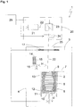
- FIG. 1 The device shown is a laser sintering or laser melting device 1. To build up an object 2, it contains a process chamber 3 with a chamber wall 4.
- a working plane 7 is defined by the upper opening of the container 5, the area of the working plane 7 lying within the opening, which can be used to build the object 2, is referred to as construction field 8.
- a carrier 10 which is movable in a vertical direction V and to which a base plate 11 is attached which closes the container 5 at the bottom and thus forms its bottom.
- the base plate 11 can be a plate formed separately from the carrier 10 and attached to the carrier 10, or it can be formed integrally with the carrier 10.
- a construction platform 12 can also be attached to the base plate 11 which the object 2 is built.
- the object 2 can, however, also be built up on the base plate 11 itself, which then serves as a construction platform.
- Fig. 1 the object 2 to be formed in the container 5 on the building platform 12 below the working plane 7 is shown in an intermediate state with several solidified layers, surrounded by building material 13 that has remained unsolidified.
- the laser sintering device 1 also contains a storage container 14 for a powdery building material 15 which can be solidified by electromagnetic radiation and a coater 16, which can be moved in a horizontal direction H, for applying the building material 15 to the construction field 8.
- a radiant heater 17 which is used for heating of the building material 15 applied to the construction field 8 is used.
- the radiant heater 17 is formed, for example, as an infrared radiator.
- the laser sintering device 1 also contains an exposure device 20 with a laser 21 which generates a laser beam 22 which is deflected via a deflection device 23 and through a focusing device 24 via a coupling window 25 which is attached to the top of the process chamber 3 in its wall 4 working level 7 is focused.
- the laser sintering device 1 also contains a control unit 29, via which the individual components of the device 1 are controlled in a coordinated manner in order to carry out the construction process.
- the control unit can also be attached partially or entirely outside the device.
- the control unit can contain a CPU, the operation of which is controlled by a computer program (software).
- the computer program can be separated be stored by the device on a storage medium from which it can be loaded into the device, in particular into the control unit.
- the carrier 10 is first lowered by a height which corresponds to the desired layer thickness.
- a layer of the powdery build-up material 15 is then applied.
- the application takes place at least over the entire cross section of the object 2 to be produced, preferably over the entire construction field 8, that is to say the area of the working plane 7, which can be lowered by a vertical movement of the carrier.
- the powdery building material is then heated by the radiant heater 17. After a working temperature has been reached, the cross section of the object 2 to be produced is scanned by the laser beam 22, so that the powdery building material 15 is solidified at the points which correspond to the cross section of the object 2 to be produced. These steps are repeated until the object 2 is completed and can be removed from the installation space.
- FIG. 13 is a schematic partial sectional view, not to scale, of an area within the process chamber 3 of FIG Fig. 1 shown device 1.
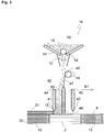
- Fig. 2 the coater 16 when moving in a first coating direction B1 over the construction field 8.
- the coater contains a coating unit 40 and a powder discharge unit 50.
- the coating unit 40 contains a first blade 41 and a second blade 42, which are spaced apart from one another in the first coating direction B1. These two blades 41, 42 at least partially close off an intermediate space in the first coating direction B1 and in its opposite direction. This space, delimited by the two blades 41, 42, is designed to receive a supply of powdery building material 15. Between the two blades 41, 42 and at a distance from them in the first coating direction B1, an intermediate wall 43 is arranged, which divides the intermediate space in the first coating direction B1 into a first chamber 44 and a second chamber 45.
- the two blades 41, 42 and thus also the space delimited by them extend transversely, preferably perpendicularly to the coating direction B, over the entire width of the area to be coated, preferably over the entire construction field 8.
- a fluidization device 46 is arranged in or on the intermediate wall 43, with which construction material can be fluidized in the two chambers.
- a gas is fed into the respective chamber and creates a fluidized bed of the powdery building material, that is, the gas gives the building material a state similar to that of a fluidized bed or fluidized bed.
- the gas is preferably preheated.
- a guide plate 47 is pivotably arranged in such a way that it guides the build-up material supplied to the coating unit 40 from the powder discharge unit 50 into one of the two chambers 44, 45.
- the guide plate 47 is preferably attached to the intermediate wall 43 such that it can pivot.
- a shaft 48 with eccentric 49 is arranged in the applicator 16 in such a way that, through its rotation, the guide plate 47 can be pivoted between the two positions in which it guides the build-up material into the first chamber 44 or into the second chamber 45.
- the powder discharge unit 50 contains a powder receptacle 51 with a funnel-shaped cross section, which is suitable for receiving a predetermined amount of powdery building material 15, and a metering device 52, for example in the form of a metering shaft, by means of which powdery building material can be dispensed to the coating unit 40 in a metered manner .
- the powder discharge unit 50 preferably contains a local radiant heater (not shown) for preheating the building material 15 and / or a fluidization device (not shown) for fluidizing the building material 15.
- the powder discharge unit 50 and the coating unit 40 are preferably arranged to be movable together with one another over the working plane, but the powder discharge unit 50 can also be movable separately from the coating unit 40.
- the application 16 or at least the powder discharge unit 50 first moves to the storage container 14 and takes a predetermined amount of the powdery building material 15 in the container 51.
- This predetermined amount of powder is preferably at least as large, more preferably greater than the amount of powder that is required for applying a layer 31 of the powdery building material 15.
- the powder 15 received in the container 51 is preferably preheated by means of the local radiant heating and / or fluidized by introducing a preferably heated gas.
- the powder discharge unit 50 moves together with the coating unit 40 in the first coating direction B1 over the construction field 8 and in the process releases powder 15 by means of the metering device 52 to the coating unit 40 moving in the first coating direction over the construction field 8.
- This powder delivery can take place continuously or at intervals.
- the powder discharge unit 50 does not need to be moved together with the coating unit 40, but only needs to be at the location of the coating unit 40 when the powder is dispensed.
- the build-up material discharged from the powder discharge unit 50 falls under its own weight and hits the guide plate 47, which is shown in FIG Fig. 2 is shown in its rest position.
- the powder slides over the guide plate 47 into the first chamber 44, which is the trailing chamber in the first direction of movement B1.
- the building material is fluidized in the first chamber 4-4 and pulled out by the first blade 41, which is the trailing blade in the first direction of movement B1, to form a uniform powder layer 31.
- the powdery build-up material is preferably dosed by the powder discharge module in such a way that a powder level in the first chamber 44 remains approximately constant.
- the pressure of the powder column 15 on the powder bed 30 also remains approximately constant, which leads to more uniform application conditions and thus to a better homogeneity and quality of the applied powder layer 31.
- a further improvement in the quality of the applied powder layer 31 is achieved in that powder is prevented from flowing out in front of the second blade 42, which is at the front in the first coating direction B1.
- the powder fills the entire area between the two blades. Since the underside of both blades is at the same height, the front blade in the coating direction has a distance from the powder bed that corresponds to the thickness of the powder layer applied. It is therefore easily possible that part of the powder, which is very mobile due to the fluidization, emerges in front of the front blade. This powder would then be compacted by both blades when the coater was passed over, which can lead to undesirable effects.
- the powder does not reach the front blade at all and therefore cannot flow out.
- the underside of the intermediate wall 43 which, regardless of the coating direction, never moves over the newly applied powder layer 31, can be at a lower level than the undersides of the two blades 41, 42. This also makes an outflow of powder in front of the intermediate wall 43 effective counteracted.
- the inertial force of the powder 15 accommodated in the first chamber 44 also counteracts the outflow in front of the partition.
- the build-up material 15 can, however, run in a direction transverse to the coating direction into areas with an increased powder requirement without a powder shortage occurring there.
- FIG. 13 is a schematic partial sectional view, not to scale, of an area within the process chamber 3 of FIG Fig. 1 shown device 1.
- Fig. 2 the applicator 16 when moving in a second coating direction B2 over the construction field 8, which is opposite to the first coating direction B1.
- Opposite does not necessarily mean an angle of 180 ° in a plan view of the working plane, but only that the second coating direction B2 has a component which points in the opposite direction to the first coating direction B1.
- the angle between the first and the second coating direction is preferably between 15 and 210 degrees, more preferably it is 180 °.
- a further powder layer 32 is now applied to the selectively solidified powder layer 31 in the second movement direction B2. This is done essentially exactly as with the first powder layer 31, so that only the differences are described here.
- the application unit 16 or at least the powder discharge unit 50 moves to an in Fig. 1 Storage container (not shown), which is arranged on the side of the construction field 8 opposite the storage container 14, and holds a predetermined amount of the powdery building material 15 in the container 51.
- the powder discharge unit 50 can also take up an amount of powder which is sufficient for the two powder layers 31, 32 before the powder layer 31 is applied.
- the powder discharge unit 50 again delivers powder 15 continuously or at intervals to the coating unit 40 moving over the construction field 8 in the second coating direction B2.
- the guide plate 47 When traveling in the second coating direction B2, the guide plate 47 is brought into a position via a rotation of the shaft 48 by the eccentric 49 attached to the shaft 48, in which the powder hitting the guide plate 47 is guided into the second chamber 45, which in the second direction of movement B2 is the trailing chamber.
- the building material is fluidized in the second chamber 45 and pulled out by the second blade 42, which is the trailing blade in the second direction of movement B2, to form a uniform powder layer 32.
- the build-up material released by the powder discharge unit 50 is therefore always taken up in the trailing chamber and pulled out into a uniform layer with the trailing blade.
- the shaft 48 is returned to the in Fig. 2
- the position shown is rotated, and the guide plate 47 returns to its starting position by a return device (not shown) such as a spring or by a guide through the eccentric 49.
- the movement of the shaft 48 can at least partially be coupled to a movement of the metering device 52 of the powder discharge unit 50, for example a metering shaft.
- the coating unit is an integral part of the coater.
- it can also be designed as a coating module that is separate from the coater and is set up to be attached to the coater so that it can be moved with the latter so that the direction in which the blades and the partition are spaced from one another coincides with the direction in which the coater can be moved over the working plane.
- the fluidization device of the coating unit can also be arranged in or on one of the blades or both blades.
- blades instead of blades, other coating elements can also be used for applying a layer of the building material, for example those which contain a roller on their underside.
- the imagesetter can, for example, comprise one or more gas or solid-state lasers or any other type of laser such as laser diodes, in particular VCSEL (Vertical Cavity Surface Emitting Laser) or VECSEL (Vertical External Cavity Surface Emitting Laser), or a line of these lasers.
- any device can be used as an exposure device with which energy can be applied selectively as wave or particle radiation to a layer of the building material.
- a laser it is possible, for example, to use another light source, an electron beam or any other energy or radiation source that is suitable for solidifying the building material.
- deflecting a beam exposure with a movable line exposure unit can also be used.
- the invention can be used.
- HSS high-speed sintering
- a material is selectively applied to the building material that reduces the radiation absorption at the points corresponding to the object cross-section increased (absorption sintering) or reduced (inhibition sintering), and then unselectively exposed over a large area or with a movable line exposure unit.
- the selective solidification of the applied building material can also take place by means of 3D printing, for example by applying an adhesive.
- the disclosure relates to the manufacture of an object by layering and selectively solidifying a building material regardless of the manner in which the building material is solidified.
- Various types of powder can be used as the building material, in particular metal powder, plastic powder, ceramic powder, sand, filled or mixed powder.
Landscapes
- Engineering & Computer Science (AREA)
- Chemical & Material Sciences (AREA)
- Materials Engineering (AREA)
- Manufacturing & Machinery (AREA)
- Mechanical Engineering (AREA)
- Physics & Mathematics (AREA)
- Optics & Photonics (AREA)
- Automation & Control Theory (AREA)
- Plasma & Fusion (AREA)
Claims (13)
- Unité d'enduction (40) destinée à équiper initialement et/ou ultérieurement un dispositif (1) pour fabriquer un objet (2) tridimensionnel par solidification sélective par couches d'un matériau de construction (15) pulvérulent, dans laquelle le dispositif (1) contient un enducteur (16) déplaçable par-dessus un champ de construction (8) pour appliquer une couche (31) du matériau de construction (15) sur le champ de construction (8) et un dispositif de solidification (20) pour une solidification sélective de la couche (31) appliquée en des emplacements qui correspondent à une section transversale de l'objet (2) à fabriquer, et conçue et/ou commandée pour répéter les étapes de l'application et de la solidification sélective, jusqu'à ce que l'objet soit fabriqué,
dans laquelle l'unité d'enduction (40) contient :deux éléments d'enduction (41, 42) espacés l'un de l'autre dans une première direction (B1) et s'étendant dans une direction transversalement à la première direction, lesquels éléments d'enduction délimitent un espace de réception pour le matériau de construction (15) pulvérulent dans la première direction (B1) et dans sa direction opposée (B2), etune paroi intermédiaire (43) qui est agencée entre les deux éléments d'enduction (41, 42) dans la première direction (B1), espacée des deux éléments d'enduction (41, 42), et s'étend dans une direction transversalement à la première direction (B1), moyennant quoi l'espace de réception est subdivisé en deux chambres (44, 45) pour le matériau de construction (15),dans lequel l'unité d'enduction (40) est aménagée pour :en fonction du déplacement de l'unité d'enduction (40) dans la première direction (B1) ou dans sa direction opposée (B2), recevoir un matériau de construction dans la chambre (44, 45) venant après dans la direction de déplacement respective, etétirer en une couche uniforme (31) le matériau de construction (15) reçu dans la chambre (44, 45) venant respectivement après avec l'élément d'enduction (41, 42) venant respectivement après. - Unité d'enduction (40) selon la revendication 1, dans laquelle dans et/ou contre au moins l'un des éléments d'enduction (41, 42) et/ou la paroi intermédiaire (43) est agencé un équipement de fluidisation (46) qui est adapté pour fluidifier le matériau de construction (15) reçu dans l'une des deux chambres (44, 45).
- Unité d'enduction selon la revendication 1 ou 2, qui contient un déflecteur (47) monté de façon pivotante, de préférence contre la paroi intermédiaire (43), pour guider un matériau de construction (15) amené jusque dans l'une des deux chambres (44, 45).
- Unité d'enduction selon la revendication 3, qui contient un arbre (48) avec un excentrique (49), lequel arbre est agencé de telle sorte que par sa rotation le déflecteur (47) puisse être pivoté.
- Enducteur (16) destiné à équiper initialement et/ou ultérieurement un dispositif (1) pour fabriquer un objet (2) tridimensionnel par solidification sélective par couches d'un matériau de construction (15) pulvérulent, dans lequel le dispositif (1) est adapté contre celui-ci pour recevoir l'enducteur (16) de telle sorte qu'il soit déplaçable par-dessus un champ de construction (8) pour appliquer une couche (31) du matériau de construction (15) sur le champ de construction (8), contient un dispositif de solidification (20) pour une solidification sélective de la couche (31) appliquée en des emplacements qui correspondent à une section transversale de l'objet (2) à fabriquer, et est conçu et/ou commandé pour répéter les étapes de l'application et de la solidification sélective, jusqu'à ce que l'objet (2) soit fabriqué,
dans lequel l'enducteur (16) comprend une unité d'enduction (40) selon l'une des revendications 1 à 4. - Enducteur (16) selon la revendication 5, comprenant en outre une unité de décharge de poudre (50) qui de préférence est réalisée de façon déplaçable ensemble avec l'unité d'enduction (40).
- Enducteur selon la revendication 6, comprenant :un déflecteur (47) monté de façon pivotante, de préférence contre la paroi intermédiaire (43) de l'unité d'enduction (40), pour guider un matériau de construction (15) amené jusque dans l'une des deux chambres (44, 45) de l'unité d'enduction (40), etun arbre (48) avec un excentrique (49), lequel arbre est agencé de telle sorte que par sa rotation le déflecteur (47) puisse être pivoté,dans lequel l'arbre (48) avec l'excentrique (49), dans son déplacement, est couplé au moins partiellement avec un déplacement d'un équipement de dosage (52) de l'unité de décharge de poudre (50).
- Dispositif (1) destiné à fabriquer un objet (2) tridimensionnel par solidification sélective par couches d'un matériau de construction (15) pulvérulent, comprenant :un enducteur (16) déplaçable par-dessus un champ de construction (8) dans une première direction (B1) et/ou dans sa direction opposée (B2) pour appliquer une couche (31) du matériau de construction (15) sur le champ de construction (8), etun dispositif de solidification (20) pour une solidification sélective de la couche (31) appliquée en des emplacements qui correspondent à une section transversale de l'objet (2) à fabriquer,dans lequel le dispositif (1) est conçu et/ou commandé pour répéter les étapes de l'application et de la solidification sélective, jusqu'à ce que l'objet (2) soit fabriqué, etdans lequel l'enducteur (16) contient une unité d'enduction (40) selon l'une des revendications 1 à 4 et/ou est conçu en tant qu'enducteur (16) selon l'une des revendications 5 à 7.
- Procédé destiné à fabriquer un objet (2) tridimensionnel par application par couches et solidification sélective d'un matériau de construction (15) pulvérulent, avec les étapes de :application d'une couche (31) du matériau de construction (15) pulvérulent sur un champ de construction (8) au moyen d'un enducteur se déplaçant dans une première direction (B1) et/ou dans sa direction opposée (B2) par-dessus le champ de construction (8),solidification sélective de la couche (31) pulvérulente appliquée en des emplacements qui correspondent à une section transversale de l'objet (2) à fabriquer, etrépétition des étapes de l'application et de la solidification sélective, jusqu'à ce que l'objet (2) soit fabriqué,dans lequel l'étape de l'application est exécutée à l'aide d'une unité d'enduction (40) comprise dans l'enducteur (16), laquelle contient :deux éléments d'enduction (41, 42) espacés l'un de l'autre dans une première direction (B1) et s'étendant dans une direction transversalement à la première direction (B1), lesquels éléments d'enduction délimitent un espace de réception pour le matériau de construction (15) pulvérulent dans la première direction (B1) et dans sa direction opposée (B2), etune paroi intermédiaire (43) qui est agencée entre les deux éléments d'enduction (41, 42) dans la première direction (B1), espacée des deux éléments d'enduction (41, 42), et s'étend dans une direction transversalement à la première direction (B1), moyennant quoi l'espace de réception est subdivisé en deux chambres (44, 45) pour le matériau de construction,dans lequel l'unité d'enduction (40), en fonction du déplacement de l'enducteur dans la première direction (B1) ou dans sa direction opposée (B2), reçoit un matériau de construction (15) dans la chambre (44, 45) venant après dans la direction de déplacement respective, etétire en une couche uniforme le matériau de construction (15) reçu dans la chambre (44, 45) venant respectivement après avec l'élément d'enduction (41, 42) venant respectivement après.
- Procédé selon la revendication 9, dans lequel le matériau de construction (15) reçu dans la chambre (44, 45) venant respectivement après est fluidifié pendant le déplacement de l'unité d'enduction (40) par-dessus le champ de construction (8).
- Procédé selon la revendication 9 ou 10, dans lequel à l'unité d'enduction (40), pendant son déplacement par-dessus le champ de construction (8), est amené, en continu ou par intervalles, un matériau de construction (15) pulvérulent depuis un module de décharge de poudre (50) se déplaçant par-dessus le champ de construction (8) avec l'unité d'enduction (40) ou séparé de celle-ci.
- Procédé selon la revendication 11, dans lequel le matériau de construction (15) pulvérulent est dosé par le module de décharge de poudre (50) de telle sorte qu'un niveau de poudre dans la chambre (44, 45) venant respectivement après demeure approximativement constant.
- Procédé selon l'une des revendications 1 à 12, dans lequel un côté inférieur de la paroi intermédiaire (43) de l'unité d'enduction (40) se situe sur un niveau inférieur à au moins l'un des côtés inférieurs des deux éléments d'enduction (41, 42).
Applications Claiming Priority (2)
| Application Number | Priority Date | Filing Date | Title |
|---|---|---|---|
| DE102015222100.8A DE102015222100A1 (de) | 2015-11-10 | 2015-11-10 | Beschichtungseinheit, Vorrichtung und Verfahren zum Herstellen eines dreidimensionalen Objekts |
| PCT/EP2016/001876 WO2017080660A1 (fr) | 2015-11-10 | 2016-11-10 | Unité de revêtement, dispositif et procédé pour la fabrication d'un objet tridimensionnel |
Publications (2)
| Publication Number | Publication Date |
|---|---|
| EP3328620A1 EP3328620A1 (fr) | 2018-06-06 |
| EP3328620B1 true EP3328620B1 (fr) | 2021-03-24 |
Family
ID=57345854
Family Applications (1)
| Application Number | Title | Priority Date | Filing Date |
|---|---|---|---|
| EP16797742.0A Active EP3328620B1 (fr) | 2015-11-10 | 2016-11-10 | Unité de revêtement et procédé pour la fabrication d'un objet tridimensionnel |
Country Status (5)
| Country | Link |
|---|---|
| US (1) | US11173658B2 (fr) |
| EP (1) | EP3328620B1 (fr) |
| CN (1) | CN108349162B (fr) |
| DE (1) | DE102015222100A1 (fr) |
| WO (1) | WO2017080660A1 (fr) |
Families Citing this family (18)
| Publication number | Priority date | Publication date | Assignee | Title |
|---|---|---|---|---|
| DE102016115575A1 (de) * | 2016-08-23 | 2018-03-01 | Cl Schutzrechtsverwaltungs Gmbh | Vorrichtung zur additiven Herstellung wenigstens eines dreidimensionalen Objekts |
| DE102016120044A1 (de) * | 2016-10-20 | 2018-04-26 | Cl Schutzrechtsverwaltungs Gmbh | Vorrichtung zur additiven Herstellung dreidimensionaler Objekte |
| US11931767B2 (en) * | 2017-04-21 | 2024-03-19 | Desktop Metal, Inc. | Metering build material in three-dimensional (3D) printing using a tool |
| BE1025291B1 (nl) * | 2017-06-06 | 2019-01-15 | Layerwise N.V. | Werkwijze en inrichting voor het doseren van een poeder voor het additief vervaardigen van een product |
| US20200130274A1 (en) * | 2017-07-05 | 2020-04-30 | Materialise N.V. | System and method for preheating of portions of building material in an additive manufacturing environment |
| US20190060998A1 (en) * | 2017-08-28 | 2019-02-28 | General Electric Company | Powder bed re-coater apparatus and methods of use thereof |
| DE102018006473A1 (de) * | 2018-08-16 | 2020-02-20 | Voxeljet Ag | Verfahren und Vorrichtung zum Herstellen von 3D-Formteilen durch Schichtaufbautechnik mittels Verschlussvorrichtung |
| WO2020092485A1 (fr) * | 2018-10-31 | 2020-05-07 | Carbon, Inc. | Appareils pour fabrication additive d'objets tridimensionnels |
| WO2020161132A1 (fr) | 2019-02-04 | 2020-08-13 | Kyocera Fineceramics Precision Gmbh | Dispositif pour la fabrication d'éléments structuraux au moyen de procédés de fabrication additive |
| EP3718746A1 (fr) | 2019-04-02 | 2020-10-07 | Concept Laser GmbH | Appareil de fabrication additive d'objets tridimensionnels |
| DE102019210120A1 (de) | 2019-07-09 | 2021-01-14 | Eos Gmbh Electro Optical Systems | Pulveraustragsmodul für eine additive Herstellvorrichtung, additive Herstellvorrichtung und Verfahren zum Aufbringen einer Pulverschicht |
| DE102019007863A1 (de) * | 2019-11-13 | 2021-05-20 | Voxeljet Ag | Partikelmaterialvorwärmvorrichtung und Verwendung in 3D-Verfahren |
| CN110947967B (zh) * | 2019-12-30 | 2023-06-06 | 西安赛隆增材技术股份有限公司 | 一种铺粉装置及3d打印设备 |
| DE102020129420A1 (de) | 2020-11-09 | 2022-05-12 | Trumpf Laser- Und Systemtechnik Gmbh | Beschichtungseinrichtung, Mittenmodul sowie Verfahren und Vorrichtung zur Herstellung von dreidimensionalen Objekten durch selektives Verfestigen eines schichtweise aufgebrachten Aufbaumaterials |
| CN112658288B (zh) * | 2020-12-10 | 2022-08-30 | 嘉兴意动能源有限公司 | 一种基轴式金属3d打印装置 |
| CN112589125B (zh) * | 2020-12-10 | 2022-08-30 | 嘉兴意动能源有限公司 | 一种基轴式金属3d打印设备 |
| DE102022132460A1 (de) * | 2022-12-07 | 2024-06-13 | Trumpf Laser- Und Systemtechnik Gmbh | Dosierungsvorrichtung, additive Fertigungsvorrichtung sowie Dosierungsverfahren |
| US20250128474A1 (en) * | 2023-10-19 | 2025-04-24 | Blue Origin Llc | Powder recycling in additive manufacturing systems, and related methods |
Family Cites Families (10)
| Publication number | Priority date | Publication date | Assignee | Title |
|---|---|---|---|---|
| US3477570A (en) * | 1967-10-31 | 1969-11-11 | Universal Oil Prod Co | Adjustable particle collection apparatus |
| FR2701869B1 (fr) * | 1993-02-25 | 1995-06-09 | Saint Gobain Vitrage Int | Dispositif de distribution de solides pulvérulents à la surface d'un substrat afin de le revêtir. |
| DE19928245B4 (de) | 1999-06-21 | 2006-02-09 | Eos Gmbh Electro Optical Systems | Einrichtung zum Zuführen von Pulver für eine Lasersintereinrichtung |
| DE10105504A1 (de) * | 2001-02-07 | 2002-08-14 | Eos Electro Optical Syst | Vorrichtung zur Behandlung von Pulver für eine Vorrichtung zum Herstellen eines dreidimensionalen Objekts, Vorrichtung zum Herstellen eines dreidimensionalen Objekts und Verfahren zum Herstellen eines dreidimensionalen Objekts |
| DE102005022308B4 (de) | 2005-05-13 | 2007-03-22 | Eos Gmbh Electro Optical Systems | Vorrichtung und Verfahren zum Herstellen eines dreidimensionalen Objekts mit einem beheizten Beschichter für pulverförmiges Aufbaumaterial |
| EP2202016B1 (fr) * | 2008-11-27 | 2012-04-25 | SLM Solutions GmbH | Dispositif d'application de poudre pour une installation de fabrication de pièces usinées en utilisant des couches de poudre à l'aide d'un rayonnement électromagnétique ou un rayonnement de particules |
| EP2859973B1 (fr) * | 2013-10-10 | 2019-12-04 | SLM Solutions Group AG | Procédé et dispositif de traitement de poudre destiné à être utilisé dans un appareil de fabrication additive de pièces tridimensionnelles |
| GB2546016B (en) * | 2014-06-20 | 2018-11-28 | Velo3D Inc | Apparatuses, systems and methods for three-dimensional printing |
| BG67063B1 (bg) * | 2015-04-09 | 2020-04-30 | „Принт Каст“ Оод | Метод и система за послойно изграждане на тримерни модели от прахообра зен материал |
| US9821502B2 (en) * | 2015-09-11 | 2017-11-21 | Ut-Battelle, Llc | Multi-orifice deposition nozzle for additive manufacturing |
-
2015
- 2015-11-10 DE DE102015222100.8A patent/DE102015222100A1/de not_active Withdrawn
-
2016
- 2016-11-10 EP EP16797742.0A patent/EP3328620B1/fr active Active
- 2016-11-10 US US15/772,583 patent/US11173658B2/en active Active
- 2016-11-10 CN CN201680065334.4A patent/CN108349162B/zh active Active
- 2016-11-10 WO PCT/EP2016/001876 patent/WO2017080660A1/fr not_active Ceased
Also Published As
| Publication number | Publication date |
|---|---|
| EP3328620A1 (fr) | 2018-06-06 |
| US20190091921A1 (en) | 2019-03-28 |
| CN108349162A (zh) | 2018-07-31 |
| CN108349162B (zh) | 2020-10-23 |
| DE102015222100A1 (de) | 2017-05-11 |
| WO2017080660A1 (fr) | 2017-05-18 |
| US11173658B2 (en) | 2021-11-16 |
Similar Documents
| Publication | Publication Date | Title |
|---|---|---|
| WO2017080660A1 (fr) | Unité de revêtement, dispositif et procédé pour la fabrication d'un objet tridimensionnel | |
| EP3263338B1 (fr) | Procédé de fabrication additive d'un objet tridimensionnel | |
| EP3408074B1 (fr) | Procédé et dispositif pour la production générative d'un objet tridimensionnel, programme et dispositif de commande | |
| EP2864108B1 (fr) | Dispositif et procédé de fabrication par couches d'un objet tridimensionnel | |
| EP3297811B1 (fr) | Procédé et dispositif de fabrication d'un objet tridimensionnel | |
| EP3275654B1 (fr) | Unité de revêtement, procédé de revêtement, dispositif et procédé et dispositif de fabrication additive d'un objet tridimensionnel | |
| EP3362259B1 (fr) | Dispositif et procédé de fabrication d'un objet en trois dimensions | |
| EP3322573B1 (fr) | Procédé et dispositif pour le dosage de matériau de construction dans un procédé de fabrication génératif | |
| EP3374158B1 (fr) | Unité de décharge de poudre, dispositif et procédé de fabrication additive d'un objet tridimensionnel | |
| WO2017008891A1 (fr) | Procédé et dispositif de fabrication d'un objet tridimensionnel | |
| EP3285988B1 (fr) | Procédé et dispositif de fabrication d'un objet tridimensionnel | |
| WO2016066317A1 (fr) | Procédé, dispositif et module de revêtement pour la réalisation d'un objet tridimensionnel | |
| EP1358059B1 (fr) | Dispositif de realisation d'un objet tridimensionnel comprenant un dispositif de traitement de poudre et procede de realisation d'un objet tridimensionnel | |
| EP3342583B1 (fr) | Procédé et dispositif de fabrication additive d'un objet tridimensionnel | |
| EP3297813B1 (fr) | Procédé et dispositif de fabrication d'un objet tridimensionnel | |
| EP3470208B1 (fr) | Dispositif de dosage, procédé et dispositif de fabrication additive d'un objet tridimensionnel | |
| EP4197628B1 (fr) | Dispositif de mélange permettant de fabriquer un mélange pulvérulent | |
| DE102018200802A1 (de) | Dosiervorrichtung, Vorrichtung und Verfahren zum generativen Herstellen eines dreidimensionalen Objekts | |
| DE102019210120A1 (de) | Pulveraustragsmodul für eine additive Herstellvorrichtung, additive Herstellvorrichtung und Verfahren zum Aufbringen einer Pulverschicht | |
| DE102017205167A1 (de) | Vorrichtung und Verfahren zum generativen Herstellen eines dreidimensionalen Objekts |
Legal Events
| Date | Code | Title | Description |
|---|---|---|---|
| STAA | Information on the status of an ep patent application or granted ep patent |
Free format text: STATUS: UNKNOWN |
|
| STAA | Information on the status of an ep patent application or granted ep patent |
Free format text: STATUS: THE INTERNATIONAL PUBLICATION HAS BEEN MADE |
|
| PUAI | Public reference made under article 153(3) epc to a published international application that has entered the european phase |
Free format text: ORIGINAL CODE: 0009012 |
|
| STAA | Information on the status of an ep patent application or granted ep patent |
Free format text: STATUS: REQUEST FOR EXAMINATION WAS MADE |
|
| 17P | Request for examination filed |
Effective date: 20180302 |
|
| AK | Designated contracting states |
Kind code of ref document: A1 Designated state(s): AL AT BE BG CH CY CZ DE DK EE ES FI FR GB GR HR HU IE IS IT LI LT LU LV MC MK MT NL NO PL PT RO RS SE SI SK SM TR |
|
| AX | Request for extension of the european patent |
Extension state: BA ME |
|
| DAV | Request for validation of the european patent (deleted) | ||
| DAX | Request for extension of the european patent (deleted) | ||
| REG | Reference to a national code |
Ref country code: DE Ref legal event code: R079 Ref document number: 502016012676 Country of ref document: DE Free format text: PREVIOUS MAIN CLASS: B29C0067000000 Ipc: B29C0064153000 |
|
| GRAP | Despatch of communication of intention to grant a patent |
Free format text: ORIGINAL CODE: EPIDOSNIGR1 |
|
| STAA | Information on the status of an ep patent application or granted ep patent |
Free format text: STATUS: GRANT OF PATENT IS INTENDED |
|
| RIC1 | Information provided on ipc code assigned before grant |
Ipc: B29C 64/205 20170101ALI20201102BHEP Ipc: B29C 64/153 20170101AFI20201102BHEP |
|
| INTG | Intention to grant announced |
Effective date: 20201125 |
|
| GRAS | Grant fee paid |
Free format text: ORIGINAL CODE: EPIDOSNIGR3 |
|
| GRAA | (expected) grant |
Free format text: ORIGINAL CODE: 0009210 |
|
| STAA | Information on the status of an ep patent application or granted ep patent |
Free format text: STATUS: THE PATENT HAS BEEN GRANTED |
|
| AK | Designated contracting states |
Kind code of ref document: B1 Designated state(s): AL AT BE BG CH CY CZ DE DK EE ES FI FR GB GR HR HU IE IS IT LI LT LU LV MC MK MT NL NO PL PT RO RS SE SI SK SM TR |
|
| REG | Reference to a national code |
Ref country code: GB Ref legal event code: FG4D Free format text: NOT ENGLISH |
|
| REG | Reference to a national code |
Ref country code: CH Ref legal event code: EP |
|
| REG | Reference to a national code |
Ref country code: DE Ref legal event code: R096 Ref document number: 502016012676 Country of ref document: DE |
|
| REG | Reference to a national code |
Ref country code: IE Ref legal event code: FG4D Free format text: LANGUAGE OF EP DOCUMENT: GERMAN |
|
| REG | Reference to a national code |
Ref country code: AT Ref legal event code: REF Ref document number: 1374049 Country of ref document: AT Kind code of ref document: T Effective date: 20210415 |
|
| REG | Reference to a national code |
Ref country code: NL Ref legal event code: FP |
|
| REG | Reference to a national code |
Ref country code: LT Ref legal event code: MG9D |
|
| PG25 | Lapsed in a contracting state [announced via postgrant information from national office to epo] |
Ref country code: BG Free format text: LAPSE BECAUSE OF FAILURE TO SUBMIT A TRANSLATION OF THE DESCRIPTION OR TO PAY THE FEE WITHIN THE PRESCRIBED TIME-LIMIT Effective date: 20210624 Ref country code: GR Free format text: LAPSE BECAUSE OF FAILURE TO SUBMIT A TRANSLATION OF THE DESCRIPTION OR TO PAY THE FEE WITHIN THE PRESCRIBED TIME-LIMIT Effective date: 20210625 Ref country code: FI Free format text: LAPSE BECAUSE OF FAILURE TO SUBMIT A TRANSLATION OF THE DESCRIPTION OR TO PAY THE FEE WITHIN THE PRESCRIBED TIME-LIMIT Effective date: 20210324 Ref country code: HR Free format text: LAPSE BECAUSE OF FAILURE TO SUBMIT A TRANSLATION OF THE DESCRIPTION OR TO PAY THE FEE WITHIN THE PRESCRIBED TIME-LIMIT Effective date: 20210324 Ref country code: NO Free format text: LAPSE BECAUSE OF FAILURE TO SUBMIT A TRANSLATION OF THE DESCRIPTION OR TO PAY THE FEE WITHIN THE PRESCRIBED TIME-LIMIT Effective date: 20210624 |
|
| PG25 | Lapsed in a contracting state [announced via postgrant information from national office to epo] |
Ref country code: LV Free format text: LAPSE BECAUSE OF FAILURE TO SUBMIT A TRANSLATION OF THE DESCRIPTION OR TO PAY THE FEE WITHIN THE PRESCRIBED TIME-LIMIT Effective date: 20210324 Ref country code: RS Free format text: LAPSE BECAUSE OF FAILURE TO SUBMIT A TRANSLATION OF THE DESCRIPTION OR TO PAY THE FEE WITHIN THE PRESCRIBED TIME-LIMIT Effective date: 20210324 Ref country code: SE Free format text: LAPSE BECAUSE OF FAILURE TO SUBMIT A TRANSLATION OF THE DESCRIPTION OR TO PAY THE FEE WITHIN THE PRESCRIBED TIME-LIMIT Effective date: 20210324 |
|
| PG25 | Lapsed in a contracting state [announced via postgrant information from national office to epo] |
Ref country code: CZ Free format text: LAPSE BECAUSE OF FAILURE TO SUBMIT A TRANSLATION OF THE DESCRIPTION OR TO PAY THE FEE WITHIN THE PRESCRIBED TIME-LIMIT Effective date: 20210324 Ref country code: EE Free format text: LAPSE BECAUSE OF FAILURE TO SUBMIT A TRANSLATION OF THE DESCRIPTION OR TO PAY THE FEE WITHIN THE PRESCRIBED TIME-LIMIT Effective date: 20210324 Ref country code: LT Free format text: LAPSE BECAUSE OF FAILURE TO SUBMIT A TRANSLATION OF THE DESCRIPTION OR TO PAY THE FEE WITHIN THE PRESCRIBED TIME-LIMIT Effective date: 20210324 Ref country code: SM Free format text: LAPSE BECAUSE OF FAILURE TO SUBMIT A TRANSLATION OF THE DESCRIPTION OR TO PAY THE FEE WITHIN THE PRESCRIBED TIME-LIMIT Effective date: 20210324 |
|
| PG25 | Lapsed in a contracting state [announced via postgrant information from national office to epo] |
Ref country code: IS Free format text: LAPSE BECAUSE OF FAILURE TO SUBMIT A TRANSLATION OF THE DESCRIPTION OR TO PAY THE FEE WITHIN THE PRESCRIBED TIME-LIMIT Effective date: 20210724 Ref country code: PL Free format text: LAPSE BECAUSE OF FAILURE TO SUBMIT A TRANSLATION OF THE DESCRIPTION OR TO PAY THE FEE WITHIN THE PRESCRIBED TIME-LIMIT Effective date: 20210324 Ref country code: PT Free format text: LAPSE BECAUSE OF FAILURE TO SUBMIT A TRANSLATION OF THE DESCRIPTION OR TO PAY THE FEE WITHIN THE PRESCRIBED TIME-LIMIT Effective date: 20210726 Ref country code: RO Free format text: LAPSE BECAUSE OF FAILURE TO SUBMIT A TRANSLATION OF THE DESCRIPTION OR TO PAY THE FEE WITHIN THE PRESCRIBED TIME-LIMIT Effective date: 20210324 Ref country code: SK Free format text: LAPSE BECAUSE OF FAILURE TO SUBMIT A TRANSLATION OF THE DESCRIPTION OR TO PAY THE FEE WITHIN THE PRESCRIBED TIME-LIMIT Effective date: 20210324 |
|
| REG | Reference to a national code |
Ref country code: DE Ref legal event code: R097 Ref document number: 502016012676 Country of ref document: DE |
|
| PG25 | Lapsed in a contracting state [announced via postgrant information from national office to epo] |
Ref country code: ES Free format text: LAPSE BECAUSE OF FAILURE TO SUBMIT A TRANSLATION OF THE DESCRIPTION OR TO PAY THE FEE WITHIN THE PRESCRIBED TIME-LIMIT Effective date: 20210324 Ref country code: AL Free format text: LAPSE BECAUSE OF FAILURE TO SUBMIT A TRANSLATION OF THE DESCRIPTION OR TO PAY THE FEE WITHIN THE PRESCRIBED TIME-LIMIT Effective date: 20210324 Ref country code: DK Free format text: LAPSE BECAUSE OF FAILURE TO SUBMIT A TRANSLATION OF THE DESCRIPTION OR TO PAY THE FEE WITHIN THE PRESCRIBED TIME-LIMIT Effective date: 20210324 |
|
| PLBE | No opposition filed within time limit |
Free format text: ORIGINAL CODE: 0009261 |
|
| STAA | Information on the status of an ep patent application or granted ep patent |
Free format text: STATUS: NO OPPOSITION FILED WITHIN TIME LIMIT |
|
| PG25 | Lapsed in a contracting state [announced via postgrant information from national office to epo] |
Ref country code: SI Free format text: LAPSE BECAUSE OF FAILURE TO SUBMIT A TRANSLATION OF THE DESCRIPTION OR TO PAY THE FEE WITHIN THE PRESCRIBED TIME-LIMIT Effective date: 20210324 |
|
| 26N | No opposition filed |
Effective date: 20220104 |
|
| PG25 | Lapsed in a contracting state [announced via postgrant information from national office to epo] |
Ref country code: IS Free format text: LAPSE BECAUSE OF FAILURE TO SUBMIT A TRANSLATION OF THE DESCRIPTION OR TO PAY THE FEE WITHIN THE PRESCRIBED TIME-LIMIT Effective date: 20210724 |
|
| PG25 | Lapsed in a contracting state [announced via postgrant information from national office to epo] |
Ref country code: MC Free format text: LAPSE BECAUSE OF FAILURE TO SUBMIT A TRANSLATION OF THE DESCRIPTION OR TO PAY THE FEE WITHIN THE PRESCRIBED TIME-LIMIT Effective date: 20210324 |
|
| REG | Reference to a national code |
Ref country code: CH Ref legal event code: PL |
|
| PG25 | Lapsed in a contracting state [announced via postgrant information from national office to epo] |
Ref country code: LU Free format text: LAPSE BECAUSE OF NON-PAYMENT OF DUE FEES Effective date: 20211110 Ref country code: BE Free format text: LAPSE BECAUSE OF NON-PAYMENT OF DUE FEES Effective date: 20211130 |
|
| REG | Reference to a national code |
Ref country code: BE Ref legal event code: MM Effective date: 20211130 |
|
| PG25 | Lapsed in a contracting state [announced via postgrant information from national office to epo] |
Ref country code: IE Free format text: LAPSE BECAUSE OF NON-PAYMENT OF DUE FEES Effective date: 20211110 |
|
| REG | Reference to a national code |
Ref country code: AT Ref legal event code: MM01 Ref document number: 1374049 Country of ref document: AT Kind code of ref document: T Effective date: 20211110 |
|
| PG25 | Lapsed in a contracting state [announced via postgrant information from national office to epo] |
Ref country code: AT Free format text: LAPSE BECAUSE OF NON-PAYMENT OF DUE FEES Effective date: 20211110 |
|
| PG25 | Lapsed in a contracting state [announced via postgrant information from national office to epo] |
Ref country code: HU Free format text: LAPSE BECAUSE OF FAILURE TO SUBMIT A TRANSLATION OF THE DESCRIPTION OR TO PAY THE FEE WITHIN THE PRESCRIBED TIME-LIMIT; INVALID AB INITIO Effective date: 20161110 |
|
| PG25 | Lapsed in a contracting state [announced via postgrant information from national office to epo] |
Ref country code: CY Free format text: LAPSE BECAUSE OF FAILURE TO SUBMIT A TRANSLATION OF THE DESCRIPTION OR TO PAY THE FEE WITHIN THE PRESCRIBED TIME-LIMIT Effective date: 20210324 |
|
| P01 | Opt-out of the competence of the unified patent court (upc) registered |
Effective date: 20230525 |
|
| PG25 | Lapsed in a contracting state [announced via postgrant information from national office to epo] |
Ref country code: LI Free format text: LAPSE BECAUSE OF NON-PAYMENT OF DUE FEES Effective date: 20220701 Ref country code: CH Free format text: LAPSE BECAUSE OF NON-PAYMENT OF DUE FEES Effective date: 20220701 |
|
| PG25 | Lapsed in a contracting state [announced via postgrant information from national office to epo] |
Ref country code: MK Free format text: LAPSE BECAUSE OF FAILURE TO SUBMIT A TRANSLATION OF THE DESCRIPTION OR TO PAY THE FEE WITHIN THE PRESCRIBED TIME-LIMIT Effective date: 20210324 |
|
| PG25 | Lapsed in a contracting state [announced via postgrant information from national office to epo] |
Ref country code: MT Free format text: LAPSE BECAUSE OF FAILURE TO SUBMIT A TRANSLATION OF THE DESCRIPTION OR TO PAY THE FEE WITHIN THE PRESCRIBED TIME-LIMIT Effective date: 20210324 |
|
| PG25 | Lapsed in a contracting state [announced via postgrant information from national office to epo] |
Ref country code: TR Free format text: LAPSE BECAUSE OF FAILURE TO SUBMIT A TRANSLATION OF THE DESCRIPTION OR TO PAY THE FEE WITHIN THE PRESCRIBED TIME-LIMIT Effective date: 20210324 |
|
| PGFP | Annual fee paid to national office [announced via postgrant information from national office to epo] |
Ref country code: NL Payment date: 20251119 Year of fee payment: 10 |
|
| PGFP | Annual fee paid to national office [announced via postgrant information from national office to epo] |
Ref country code: DE Payment date: 20251119 Year of fee payment: 10 |
|
| PGFP | Annual fee paid to national office [announced via postgrant information from national office to epo] |
Ref country code: GB Payment date: 20251121 Year of fee payment: 10 |
|
| PGFP | Annual fee paid to national office [announced via postgrant information from national office to epo] |
Ref country code: IT Payment date: 20251125 Year of fee payment: 10 |
|
| PGFP | Annual fee paid to national office [announced via postgrant information from national office to epo] |
Ref country code: FR Payment date: 20251126 Year of fee payment: 10 |