EP3329295B1 - Winkel- und positionserfassung mit arrays von antennen - Google Patents
Winkel- und positionserfassung mit arrays von antennen Download PDFInfo
- Publication number
- EP3329295B1 EP3329295B1 EP16831170.2A EP16831170A EP3329295B1 EP 3329295 B1 EP3329295 B1 EP 3329295B1 EP 16831170 A EP16831170 A EP 16831170A EP 3329295 B1 EP3329295 B1 EP 3329295B1
- Authority
- EP
- European Patent Office
- Prior art keywords
- transmitter
- receiver
- antenna array
- uav
- matrix
- Prior art date
- Legal status (The legal status is an assumption and is not a legal conclusion. Google has not performed a legal analysis and makes no representation as to the accuracy of the status listed.)
- Active
Links
Images








Classifications
-
- G—PHYSICS
- G01—MEASURING; TESTING
- G01S—RADIO DIRECTION-FINDING; RADIO NAVIGATION; DETERMINING DISTANCE OR VELOCITY BY USE OF RADIO WAVES; LOCATING OR PRESENCE-DETECTING BY USE OF THE REFLECTION OR RERADIATION OF RADIO WAVES; ANALOGOUS ARRANGEMENTS USING OTHER WAVES
- G01S13/00—Systems using the reflection or reradiation of radio waves, e.g. radar systems; Analogous systems using reflection or reradiation of waves whose nature or wavelength is irrelevant or unspecified
- G01S13/02—Systems using reflection of radio waves, e.g. primary radar systems; Analogous systems
- G01S13/50—Systems of measurement based on relative movement of target
- G01S13/505—Systems of measurement based on relative movement of target using Doppler effect for determining closest range to a target or corresponding time, e.g. miss-distance indicator
-
- B—PERFORMING OPERATIONS; TRANSPORTING
- B64—AIRCRAFT; AVIATION; COSMONAUTICS
- B64U—UNMANNED AERIAL VEHICLES [UAV]; EQUIPMENT THEREFOR
- B64U10/00—Type of UAV
- B64U10/10—Rotorcrafts
- B64U10/13—Flying platforms
- B64U10/14—Flying platforms with four distinct rotor axes, e.g. quadcopters
-
- G—PHYSICS
- G01—MEASURING; TESTING
- G01S—RADIO DIRECTION-FINDING; RADIO NAVIGATION; DETERMINING DISTANCE OR VELOCITY BY USE OF RADIO WAVES; LOCATING OR PRESENCE-DETECTING BY USE OF THE REFLECTION OR RERADIATION OF RADIO WAVES; ANALOGOUS ARRANGEMENTS USING OTHER WAVES
- G01S13/00—Systems using the reflection or reradiation of radio waves, e.g. radar systems; Analogous systems using reflection or reradiation of waves whose nature or wavelength is irrelevant or unspecified
- G01S13/003—Bistatic radar systems; Multistatic radar systems
-
- G—PHYSICS
- G01—MEASURING; TESTING
- G01S—RADIO DIRECTION-FINDING; RADIO NAVIGATION; DETERMINING DISTANCE OR VELOCITY BY USE OF RADIO WAVES; LOCATING OR PRESENCE-DETECTING BY USE OF THE REFLECTION OR RERADIATION OF RADIO WAVES; ANALOGOUS ARRANGEMENTS USING OTHER WAVES
- G01S13/00—Systems using the reflection or reradiation of radio waves, e.g. radar systems; Analogous systems using reflection or reradiation of waves whose nature or wavelength is irrelevant or unspecified
- G01S13/02—Systems using reflection of radio waves, e.g. primary radar systems; Analogous systems
- G01S13/06—Systems determining position data of a target
- G01S13/42—Simultaneous measurement of distance and other co-ordinates
-
- G—PHYSICS
- G01—MEASURING; TESTING
- G01S—RADIO DIRECTION-FINDING; RADIO NAVIGATION; DETERMINING DISTANCE OR VELOCITY BY USE OF RADIO WAVES; LOCATING OR PRESENCE-DETECTING BY USE OF THE REFLECTION OR RERADIATION OF RADIO WAVES; ANALOGOUS ARRANGEMENTS USING OTHER WAVES
- G01S13/00—Systems using the reflection or reradiation of radio waves, e.g. radar systems; Analogous systems using reflection or reradiation of waves whose nature or wavelength is irrelevant or unspecified
- G01S13/02—Systems using reflection of radio waves, e.g. primary radar systems; Analogous systems
- G01S13/50—Systems of measurement based on relative movement of target
- G01S13/58—Velocity or trajectory determination systems; Sense-of-movement determination systems
- G01S13/581—Velocity or trajectory determination systems; Sense-of-movement determination systems using transmission of interrupted pulse modulated waves and based upon the Doppler effect resulting from movement of targets
- G01S13/582—Velocity or trajectory determination systems; Sense-of-movement determination systems using transmission of interrupted pulse modulated waves and based upon the Doppler effect resulting from movement of targets adapted for simultaneous range and velocity measurements
-
- G—PHYSICS
- G01—MEASURING; TESTING
- G01S—RADIO DIRECTION-FINDING; RADIO NAVIGATION; DETERMINING DISTANCE OR VELOCITY BY USE OF RADIO WAVES; LOCATING OR PRESENCE-DETECTING BY USE OF THE REFLECTION OR RERADIATION OF RADIO WAVES; ANALOGOUS ARRANGEMENTS USING OTHER WAVES
- G01S13/00—Systems using the reflection or reradiation of radio waves, e.g. radar systems; Analogous systems using reflection or reradiation of waves whose nature or wavelength is irrelevant or unspecified
- G01S13/74—Systems using reradiation of radio waves, e.g. secondary radar systems; Analogous systems
- G01S13/82—Systems using reradiation of radio waves, e.g. secondary radar systems; Analogous systems wherein continuous-type signals are transmitted
- G01S13/825—Systems using reradiation of radio waves, e.g. secondary radar systems; Analogous systems wherein continuous-type signals are transmitted with exchange of information between interrogator and responder
-
- G—PHYSICS
- G01—MEASURING; TESTING
- G01S—RADIO DIRECTION-FINDING; RADIO NAVIGATION; DETERMINING DISTANCE OR VELOCITY BY USE OF RADIO WAVES; LOCATING OR PRESENCE-DETECTING BY USE OF THE REFLECTION OR RERADIATION OF RADIO WAVES; ANALOGOUS ARRANGEMENTS USING OTHER WAVES
- G01S13/00—Systems using the reflection or reradiation of radio waves, e.g. radar systems; Analogous systems using reflection or reradiation of waves whose nature or wavelength is irrelevant or unspecified
- G01S13/88—Radar or analogous systems specially adapted for specific applications
-
- G—PHYSICS
- G01—MEASURING; TESTING
- G01S—RADIO DIRECTION-FINDING; RADIO NAVIGATION; DETERMINING DISTANCE OR VELOCITY BY USE OF RADIO WAVES; LOCATING OR PRESENCE-DETECTING BY USE OF THE REFLECTION OR RERADIATION OF RADIO WAVES; ANALOGOUS ARRANGEMENTS USING OTHER WAVES
- G01S3/00—Direction-finders for determining the direction from which infrasonic, sonic, ultrasonic or electromagnetic waves, or particle emission, not having a directional significance, are being received
- G01S3/02—Direction-finders for determining the direction from which infrasonic, sonic, ultrasonic or electromagnetic waves, or particle emission, not having a directional significance, are being received using radio waves
- G01S3/14—Systems for determining direction or deviation from predetermined direction
- G01S3/46—Systems for determining direction or deviation from predetermined direction using antennas spaced apart and measuring phase or time difference between signals therefrom, i.e. path-difference systems
- G01S3/48—Systems for determining direction or deviation from predetermined direction using antennas spaced apart and measuring phase or time difference between signals therefrom, i.e. path-difference systems the waves arriving at the antennas being continuous or intermittent and the phase difference of signals derived therefrom being measured
-
- G—PHYSICS
- G01—MEASURING; TESTING
- G01S—RADIO DIRECTION-FINDING; RADIO NAVIGATION; DETERMINING DISTANCE OR VELOCITY BY USE OF RADIO WAVES; LOCATING OR PRESENCE-DETECTING BY USE OF THE REFLECTION OR RERADIATION OF RADIO WAVES; ANALOGOUS ARRANGEMENTS USING OTHER WAVES
- G01S7/00—Details of systems according to groups G01S13/00, G01S15/00, G01S17/00
- G01S7/02—Details of systems according to groups G01S13/00, G01S15/00, G01S17/00 of systems according to group G01S13/00
- G01S7/04—Display arrangements
- G01S7/06—Cathode-ray tube displays or other two dimensional or three-dimensional displays
-
- G—PHYSICS
- G05—CONTROLLING; REGULATING
- G05D—SYSTEMS FOR CONTROLLING OR REGULATING NON-ELECTRIC VARIABLES
- G05D1/00—Control of position, course, altitude or attitude of land, water, air or space vehicles, e.g. using automatic pilots
- G05D1/0011—Control of position, course, altitude or attitude of land, water, air or space vehicles, e.g. using automatic pilots associated with a remote control arrangement
- G05D1/0022—Control of position, course, altitude or attitude of land, water, air or space vehicles, e.g. using automatic pilots associated with a remote control arrangement characterised by the communication link
-
- G—PHYSICS
- G05—CONTROLLING; REGULATING
- G05D—SYSTEMS FOR CONTROLLING OR REGULATING NON-ELECTRIC VARIABLES
- G05D1/00—Control of position, course, altitude or attitude of land, water, air or space vehicles, e.g. using automatic pilots
- G05D1/0011—Control of position, course, altitude or attitude of land, water, air or space vehicles, e.g. using automatic pilots associated with a remote control arrangement
- G05D1/0033—Control of position, course, altitude or attitude of land, water, air or space vehicles, e.g. using automatic pilots associated with a remote control arrangement by having the operator tracking the vehicle either by direct line of sight or via one or more cameras located remotely from the vehicle
-
- G—PHYSICS
- G08—SIGNALLING
- G08G—TRAFFIC CONTROL SYSTEMS
- G08G5/00—Traffic control systems for aircraft
- G08G5/20—Arrangements for acquiring, generating, sharing or displaying traffic information
- G08G5/22—Arrangements for acquiring, generating, sharing or displaying traffic information located on the ground
-
- G—PHYSICS
- G08—SIGNALLING
- G08G—TRAFFIC CONTROL SYSTEMS
- G08G5/00—Traffic control systems for aircraft
- G08G5/20—Arrangements for acquiring, generating, sharing or displaying traffic information
- G08G5/26—Transmission of traffic-related information between aircraft and ground stations
-
- G—PHYSICS
- G08—SIGNALLING
- G08G—TRAFFIC CONTROL SYSTEMS
- G08G5/00—Traffic control systems for aircraft
- G08G5/50—Navigation or guidance aids
- G08G5/55—Navigation or guidance aids for a single aircraft
-
- G—PHYSICS
- G08—SIGNALLING
- G08G—TRAFFIC CONTROL SYSTEMS
- G08G5/00—Traffic control systems for aircraft
- G08G5/50—Navigation or guidance aids
- G08G5/57—Navigation or guidance aids for unmanned aircraft
-
- G—PHYSICS
- G08—SIGNALLING
- G08G—TRAFFIC CONTROL SYSTEMS
- G08G5/00—Traffic control systems for aircraft
- G08G5/70—Arrangements for monitoring traffic-related situations or conditions
- G08G5/72—Arrangements for monitoring traffic-related situations or conditions for monitoring traffic
- G08G5/723—Arrangements for monitoring traffic-related situations or conditions for monitoring traffic from the aircraft
-
- G—PHYSICS
- G08—SIGNALLING
- G08G—TRAFFIC CONTROL SYSTEMS
- G08G5/00—Traffic control systems for aircraft
- G08G5/70—Arrangements for monitoring traffic-related situations or conditions
- G08G5/72—Arrangements for monitoring traffic-related situations or conditions for monitoring traffic
- G08G5/727—Arrangements for monitoring traffic-related situations or conditions for monitoring traffic from a ground station
-
- H—ELECTRICITY
- H04—ELECTRIC COMMUNICATION TECHNIQUE
- H04L—TRANSMISSION OF DIGITAL INFORMATION, e.g. TELEGRAPHIC COMMUNICATION
- H04L67/00—Network arrangements or protocols for supporting network services or applications
- H04L67/01—Protocols
- H04L67/12—Protocols specially adapted for proprietary or special-purpose networking environments, e.g. medical networks, sensor networks, networks in vehicles or remote metering networks
-
- H—ELECTRICITY
- H04—ELECTRIC COMMUNICATION TECHNIQUE
- H04W—WIRELESS COMMUNICATION NETWORKS
- H04W4/00—Services specially adapted for wireless communication networks; Facilities therefor
- H04W4/02—Services making use of location information
- H04W4/023—Services making use of location information using mutual or relative location information between multiple location based services [LBS] targets or of distance thresholds
-
- B—PERFORMING OPERATIONS; TRANSPORTING
- B64—AIRCRAFT; AVIATION; COSMONAUTICS
- B64U—UNMANNED AERIAL VEHICLES [UAV]; EQUIPMENT THEREFOR
- B64U2101/00—UAVs specially adapted for particular uses or applications
- B64U2101/30—UAVs specially adapted for particular uses or applications for imaging, photography or videography
-
- B—PERFORMING OPERATIONS; TRANSPORTING
- B64—AIRCRAFT; AVIATION; COSMONAUTICS
- B64U—UNMANNED AERIAL VEHICLES [UAV]; EQUIPMENT THEREFOR
- B64U2201/00—UAVs characterised by their flight controls
- B64U2201/20—Remote controls
-
- G—PHYSICS
- G01—MEASURING; TESTING
- G01S—RADIO DIRECTION-FINDING; RADIO NAVIGATION; DETERMINING DISTANCE OR VELOCITY BY USE OF RADIO WAVES; LOCATING OR PRESENCE-DETECTING BY USE OF THE REFLECTION OR RERADIATION OF RADIO WAVES; ANALOGOUS ARRANGEMENTS USING OTHER WAVES
- G01S13/00—Systems using the reflection or reradiation of radio waves, e.g. radar systems; Analogous systems using reflection or reradiation of waves whose nature or wavelength is irrelevant or unspecified
- G01S13/02—Systems using reflection of radio waves, e.g. primary radar systems; Analogous systems
- G01S2013/0236—Special technical features
- G01S2013/0245—Radar with phased array antenna
- G01S2013/0254—Active array antenna
-
- G—PHYSICS
- G05—CONTROLLING; REGULATING
- G05D—SYSTEMS FOR CONTROLLING OR REGULATING NON-ELECTRIC VARIABLES
- G05D1/00—Control of position, course, altitude or attitude of land, water, air or space vehicles, e.g. using automatic pilots
- G05D1/10—Simultaneous control of position or course in three dimensions
- G05D1/101—Simultaneous control of position or course in three dimensions specially adapted for aircraft
- G05D1/102—Simultaneous control of position or course in three dimensions specially adapted for aircraft specially adapted for vertical take-off of aircraft
-
- G—PHYSICS
- G05—CONTROLLING; REGULATING
- G05D—SYSTEMS FOR CONTROLLING OR REGULATING NON-ELECTRIC VARIABLES
- G05D2111/00—Details of signals used for control of position, course, altitude or attitude of land, water, air or space vehicles
- G05D2111/30—Radio signals
Definitions
- the present invention relates generally to position sensing through radar and, more particularly, to methods for sensing relative positions of objects using arrays of antennas.
- Radar systems have traditionally been used to detect relatively large objects up to hundreds of miles away from a high power transmitting radar antenna.
- Contemporary systems are commonly used to detect relatively dense objects or object surfaces that are multiple square feet in surface profile, such as potential collision surfaces relative to a vehicle (e.g., road surfaces, walls, vehicle panels, and/or other potential collision surfaces).
- a vehicle e.g., road surfaces, walls, vehicle panels, and/or other potential collision surfaces.
- traditional radar systems have used (and still commonly use) rotating or actuated antennas in order to scan the radar over a large solid angle or to track objects/surfaces
- more contemporary systems can employ arrays of antennas in order to scan solid angles without requiring physical motion of the array and/or to provide a more directional high gain transmit or receive beam than typically possible with a single antenna element.
- US 2011/0105032 A1 describes a wireless communication system comprising transmitting and receiving antenna arrays. During a training process a channel response matrix is obtained to obtain an optimal signal phase of the antenna array between the transmitter and receiver. Based on this matrix an antenna weigh vector is obtained that can be applied to the antenna array for having optimal communication quality.
- US 2005/0270229 A1 describes a positioning system with a transmit element for sending at least one electromagnetic pulse, and a receiving antenna array with a plurality of receive elements. Where each of the receive elements receive the return pulse from which the position of an object is determined.
- Fig. 1 illustrates a block diagram 100 of an object sensing system 110 in accordance with an embodiment of the disclosure.
- system 110 may be implemented as compact, portable, and/or wearable device configured to detect a position (e.g., angle and/or range) of an object 130 relative to system 110. More generally, system 110 may be implemented as any device or system including a transmitter antenna array 124 and a receiver antenna array 128 configured to detect the position of object 130 using the methods described herein.
- the AoA or AoD with respect to a detected object can be used to calculate corresponding frequency components, similar to performing a Doppler frequency calculation in the propagation direction.
- the peaks of the frequency component in the series of AoAs or AoDs correspond to the speed and direction (e.g., velocity) of the angular movement.
- the measured AoAs or AoDs are conformed to a time series of: exp j 2 ⁇ d ⁇ sin ⁇ 1 , exp j 2 ⁇ d ⁇ sin ⁇ 2 , ... , and exp j 2 ⁇ d ⁇ sin ⁇ n , which, using (5) and (3) can be interchangeably expressed as: exp j ⁇ 1 , exp j ⁇ 2 , ... , and exp j ⁇ ⁇ n , the discrete Fourier transform (DFT) of the series can be calculated in order to perform frequency analysis on the time series.
- DFT discrete Fourier transform
- sampling time T can also be reduced to increase accuracy of t k , but if time-adjacent impulses are too close to each other, and depending on the shape of the waveform p(t) and overall channel/system SNR, the channel response may effectively merge into a single impulse and render the process inefficient and/or inaccurate/unreliable.
- Typical sampling rates of embodiments of the present disclosure can approach 2-3 GHz and produce reliable results.
- a logic device scans a transmitter antenna array and a receiver antenna array through designated channels.
- controller 112 and/or co-controller 120 may be configured to scan transmitter antenna array 124 and receiver antenna array 128 through the channels designated in block 502 to measure channel responses corresponding to each one of the designated channels.
- controller 112 may be configured to form a measurement matrix (e.g., A) comprising entries corresponding to each measured channel response.
- controller 112 may be configured to derive a channel matrix (e.g., H) from the measurement matrix and the transmitter and receiver AWV matrices designated in block 502.
- controller 112 may be configured to form a channel matrix comprising entries corresponding to each measured channel response.
- controller 112 may be configured to determine a first plurality of phase differences between signals in the measured channel responses corresponding to adjacent antenna elements along the first major axis 250 within either transmitter antenna array 124 or receiver antenna array 128, to determine a second plurality of phase differences between signals in the measured channel responses corresponding to adjacent antenna elements along the second major axis 252 within either transmitter antenna array 124 or receiver antenna array 128, and then to determine directional vector 140 or 144 to or from object 130, in the form of an angle of departure (AoD) or an angle of arrival (AoA), by averaging the first plurality of determined phase differences, separately averaging the second plurality of determined phase differences, and converting the resulting first and second average phase differences into the AoD or AoA.
- AoD angle of departure
- AoA angle of arrival
- controller 112 may be configured to determine directional vector 140 and/or 144 to or from object 130 by comparing tabulated calibration values to corresponding measured channel responses in the channel matrix.
- system 110 may be configured to perform a calibration process (e.g., shortly after manufacture) including measuring the channel responses of various calibration objects as each is presented to system 110/surface 111 over a particular range of AoDs and AoAs.
- controller 112 may be configured to repeatedly scan transmitter antenna array 124 and receiver antenna array 128 through the channels designated in block 502 over a period of time to generate a time series of the measured channel responses provided in block 504, to determine a time series of average phase differences based on the time series of measured channel responses, and to determine an average angular velocity of object 130 from the time series of average phase differences by applying a Fourier transform to a form of the time series of average phase differences and identifying a peak in the resulting transformation as the average angular velocity.
- wireless link 620 may communicate using a licensed RF band licensed by the operator or manufacturer.
- wireless link 620 may be an infrared optical communication signal, an ultrasonic communication signal, and/or other communication signals with different characteristic than typical RF signals.
- the receivers of both UAV 630 and UAV controller 610 can be configured to constantly measure the power of received signals.
- UAV system 600 may be configured to use adaptive modulation and rate adaptation (e.g., to change the data rate) to maintain or increase link quality. If the received signal becomes relatively weak, UAV controller 610 or UAV 630 may be configured to implement more robust modulation so as to require less power to achieve a certain link quality. Power measurements may be used to drive adaptive modulation if the measured received power is communicated back from a receiving device (e.g., UAV 630) to a transmitting device (e.g., UAV controller 610).
- a receiving device e.g., UAV 630
- UAV controller 610 e.g., UAV controller 610
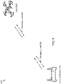
- Fig. 11 illustrates a diagram of angles of departure and arrival with respect to transmitter and receiver antenna arrays for an unmanned aerial vehicle system in accordance with an embodiment of the disclosure.
- Fig. 11 illustrates that different antenna elements experience signals having different phase shifts depending on the angle of arrival or angle of departure (e.g., corresponding to directional vectors between UAV controller 610 and UAV 630). Because determining the angle of arrival is the same problem as determining the angle of departure, the angle of departure is used for explanation purposes, but similar methods may also be applicable to angle of arrival.
- Fig. 12 illustrates a process 1200 to operate unmanned aerial vehicle system 600 in accordance with an embodiment of the disclosure.
- the operations of Fig. 12 may be implemented as software instructions executed by one or more logic devices associated with corresponding electronic devices, sensors, and/or structures depicted in Figs. 1 through 2E and 6-11 . More generally, the operations of Fig. 12 may be implemented with any combination of software instructions and/or electronic hardware (e.g., inductors, capacitors, amplifiers, actuators, or other analog and/or digital components). It should be appreciated that any step, sub-step, sub-process, or block of processes 1200 may be performed in an order or arrangement different from the embodiments illustrated by Fig. 12 .
- a logic device communicates link state data corresponding to an established wireless link.
- a controller of UAV controller 610 or UAV 630 may be configured to transmit and/or receive link state data corresponding to wireless link 620 over wireless link 620.
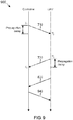
- the link state data may include a plurality of time stamps corresponding to transmissions and receptions of at least two timing measurement packets 710 and 720, a first one transmitted from UAV controller 610 to UAV 630 and a second one received by UAV controller 610 from UAV 630.
- the controller may be configured to determine a propagation delay associated with wireless link 620 from the plurality of time stamps and determine a range/distance between UAV controller 610 and UAV 630 based on the propagation delay.
- the controller may also be configured to determine a time series of propagation delays associated with wireless link 620 from the plurality of time stamps, detect a change in the time series of propagation delays indicating a transition in a link state of wireless link 620 between a LOS link state and a NLOS link state, and notify a user of UAV controller 610 of the transition in the link state, such as by visual notification on a display of UAV controller 610, or as by an audible notification generated by a speaker/transducer of UAV controller 610.
- Such change may include a relatively abrupt or discontinuous change in the time series of propagation delays, such as a greater than 10% change in a single time step, for example.
- a logic device communicates UAV operational data over an established wireless link.
- a controller of UAV controller 610 or UAV 630 may be configured to transmit and/or receive UAV operational data over wireless link 620, where the UAV operational data is configured to control operation of UAV 630, and where at least a portion of the UAV operational data may be adjusted based, at least in part, on the link state data communicated in block 1204.
- a controller of UAV controller 610 may be configured to adjust received UAV operational data to cause UAV 630 to notify a user of UAV controller 610 of the transition in the link state (e.g., by visual or audible indicator).
- the controller of UAV controller 610 may alternatively and/or additionally configured to adjust a transmit and/or receive power, signal modulation, or data rate to increase a link quality of wireless link 620 and re-establish a LOS link state, or to transmit such adjustments as UAV operational data to UAV 630, which may be configured to implement similar measures.
- a controller of UAV controller 610 or UAV 630 may be configured to detect UAV 630 exceeding a predefined (e.g., by the parent of a user) safety limitation on the speed and/or altitude of UAV 630, for example, and/or other regulatory speed, position (e.g., airport/light path restrictions), and/or altitude limitations, from the link state data, and adjust UAV operational data before it is used to control operation of UAV 630 to perform one or more various flight operations configured to adhere to the safety and/or regulatory limitations.
- a controller of UAV controller 610 or UAV 630 may be configured to adjust the UAV operational data to limit upward vertical velocity when nearing an altitude limit, to cause UAV 630 to drop below an altitude limit, and/or to enter a return-to-home mode if any predefined limits are exceeded during operation of UAV 630.
- the link state data may include a time series of a plurality of power measurements corresponding to receptions of the link state data in block 1204 and/or the UAV operational data in block 1206 by UAV controller 610 or UAV 630 over wireless link 620.
- the controller may be configured to measure the power of received transmissions of link state data and/or operational data.
- the controller may be configured to detect a change in link gain of wireless link 620 in the time series of power measurements and adjust a modulation of the wireless link and/or increase or decrease a transmission data rate according to the detected change in link gain, as appropriate.
- the first and second directional vectors are not parallel, then one of the two devices is likely measuring a reflected beam, which may be causing a decrease in the link gain of wireless link 620.
- at least one of the first and second directional vectors may be determined by measuring a phase difference between adjacent antenna elements in a transmitter antenna array or a receiver antenna array in UAV controller 610 and/or UAV 630.
- Software in accordance with the present disclosure can be stored on one or more non-transitory machine readable mediums. It is also contemplated that software identified herein can be implemented using one or more general purpose or specific purpose computers and/or computer systems, networked and/or otherwise. Where applicable, the ordering of various steps described herein can be changed, combined into composite steps, and/or separated into substeps to provide features described herein.
Landscapes
- Engineering & Computer Science (AREA)
- Remote Sensing (AREA)
- Radar, Positioning & Navigation (AREA)
- Physics & Mathematics (AREA)
- General Physics & Mathematics (AREA)
- Aviation & Aerospace Engineering (AREA)
- Computer Networks & Wireless Communication (AREA)
- Automation & Control Theory (AREA)
- Signal Processing (AREA)
- Electromagnetism (AREA)
- Medical Informatics (AREA)
- General Health & Medical Sciences (AREA)
- Computing Systems (AREA)
- Health & Medical Sciences (AREA)
- Mechanical Engineering (AREA)
- Radar Systems Or Details Thereof (AREA)
- Variable-Direction Aerials And Aerial Arrays (AREA)
Claims (12)
- Ein Verfahren für ein Objekterfassungssystem, das Folgendes aufweist:Designieren (502) einer Vielzahl von Sender- und Empfängerkanälen für ein Senderantennen-Array bzw. eine Senderantennenanordnung (124) und ein Empfängerantennen-Array bzw. eine Empfängerantennenanordnung (128) des Objekterfassungssystems (110), wobei ein Senderkanal ein Antennenelement oder eine Kombination von Antennenelementen der Senderantennenanordnung (124) nutzt und ein Empfängerkanal ein Antennenelement oder eine Kombination von Antennenelementen der Empfängerantennenanordnung (128) nutzt;Scannen bzw. Abtasten (504) der Senderantennenanordnung (124) und der Empfängerantennenanordnung (128) durch die designierten Kanäle zum Messen von Kanalantworten entsprechend einem jeden der designierten Kanäle;Bilden einer Messungsmatrix, die Einträge entsprechend jeder gemessenen Kanalantwort aufweist, wobei das Designieren der Vielzahl von Sender- und Empfängerkanälen Folgendes aufweist:Bilden einer Senderamplitudengewichtungsvektor- bzw. Sender-AWV-Matrix (AWV = amplitude weight vector), die einen oder mehrere Sender-AWVs entsprechend jedem Senderkanal in der Vielzahl von Sender- und Empfängerkanälen aufweist, undBilden einer Empfänger-AWV-Matrix, die einen oder mehrere Empfänger-AWVs entsprechend jedem Empfängerkanal in der Vielzahl von Sender- und Empfängerkanälen aufweist;Herleiten einer Kanalmatrix aus der Messungsmatrix, der Sender-AWV-Matrix und der Empfänger-AWV-Matrix; undBestimmen (506) eines Richtungsvektors bzw. direktionalen Vektors zu einem oder von einem Objekt (130) durch Durchführen einer Singulärwertzerlegung auf der Kanalmatrix zum Bestimmen wenigstens eines größten Singulärwertes entsprechend dem direktionalen Vektor zu oder von dem Objekt.
- Verfahren nach Anspruch 1, wobei die Sender-AWV-Matrix und die Empfänger-AWV-Matrix jeweils eine Hadamard-Matrix aufweisen.
- Verfahren nach Anspruch 1, wobei die Sender-AWV-Matrix und die Empfänger-AWV-Matrix jeweils AWVs aufweisen die konfiguriert sind zum Fokussieren der designierten Kanäle innerhalb eines bestimmten Subsatzes eines verfügbaren Detektionsbereichs, wobei das Verfahren weiter Folgendes aufweist:
Bestimmen des direktionalen Vektors zu dem oder von dem Objekt durch Durchführen einer Singulärwertzerlegung auf der Messungsmatrix zum Bestimmen wenigstens eines größten Singulärwertes und eines entsprechenden Messungsmatrixsingulärvektors, und durch Anwenden einer Transformationsmatrix basierend auf der Sender-AWV-Matrix oder der Empfänger-AWV-Matrix auf den Messungsmatrixsingulärvektor zum Transformieren des Messungsmatrixsingulärvektors in den direktionalen Vektor zu oder von dem Objekt. - Verfahren nach Anspruch 1, das weiter Folgendes aufweist:Bilden einer Kanalmatrix, die Einträge aufweist, die jeder gemessenen Kanalantwort entsprechen, wobei die designierten Kanäle Paaren von individuellen Antennenelementen entsprechen, die ein Antennenelement von jeder von der Senderantennenanordnung und der Empfängerantennenanordnung aufweisen; undBestimmen des direktionalen Vektors zu oder von dem Objekt durch Durchführen einer Singulärwertzerlegung auf der Kanalmatrix zum Bestimmen wenigstens eines größten Singulärwertes entsprechend dem direktionalen Vektor zu oder von dem Objekt.
- Verfahren nach Anspruch 1, wobei die designierten Kanäle unterschiedlichen Sender- oder Empfänger-Beam- bzw. -Strahlwinkeln relativ zu einer Emissionsoberfläche der Senderantennenanordnung und/oder der Empfängerantennenanordnung entsprechen, wobei das Verfahren weiter Folgendes aufweist:
Bestimmen des direktionalen Vektors zu oder von dem Objekt, in der Form eines Abstrahlwinkels bzw. AoD (AoD = angle of departure) oder Ankunftswinkels bzw. AoA (AoA = angle of arrival) durch Identifizieren einer der gemessenen Kanalantworten, die einen Spitzensignalpegel aufweist, und Festlegen des AoD oder AoA auf den Sender- oder Empfängerstrahlwinkel entsprechend der einen gemessenen Kanalantwort, die den Spitzensignalpegel aufweist. - Verfahren nach Anspruch 1, wobei die designierten Kanäle Paaren von individuellen Antennenelementen entsprechen, die ein Antennenelement von jedem von der Senderantennenanordnung und der Empfängerantennenanordnung aufweisen, wobei das Verfahren weiter Folgendes aufweist:Bestimmen einer Vielzahl von Phasendifferenzen zwischen Signalen in den gemessenen Kanalantworten entsprechend benachbarten bzw. angrenzenden Antennenelementen innerhalb entweder der Senderantennenanordnung oder der Empfängerantennenanordnung; undBestimmen des direktionalen Vektors zu oder von dem Objekt, in der Form eines Abstrahlwinkels bzw. AoD (AoD = angle of departure) oder Ankunftswinkels bzw. AoA (AoA = angle of arrival) durch Mitteln der Vielzahl von bestimmten Phasendifferenzen und Wandeln der sich ergebenden mittleren Phasendifferenz in den AoD oder AoA.
- Verfahren nach Anspruch 6, das weiter Folgendes aufweist:wiederholtes Scannen der Senderantennenanordnung und der Empfängerantennenanordnung durch die designierten Kanäle über eine Zeitperiode zum Generieren einer Zeitreihe der gemessenen Kanalantworten;Bestimmen einer Zeitreihe der AoDs oder AoAs basierend auf den Zeitreihen von gemessenen Kanalantworten; undBestimmen einer mittleren Winkelgeschwindigkeit des Objekts aus den Zeitreihen von AoDs oder AoAs durch Anwenden einer Fourier-Transformation auf die Zeitreihen von AoDs oder AoAs und Identifizieren eines Spitzenwertes in der sich ergebenden Transformation als die mittlere Winkelgeschwindigkeit.
- Verfahren nach Anspruch 1, wobei die designierten Kanäle Paaren von individuellen Antennenelementen entsprechen, die ein Antennenelement von jedem von der Senderantennenanordnung und der Empfängerantennenanordnung aufweisen, und wobei die Senderantennenanordnung und/oder die Empfängerantennenanordnung eine zweidimensionale Antennenanordnung aufweist, die erste und zweite Hauptachsen hat, wobei das Verfahren weiter Folgendes aufweist:Bestimmen einer ersten Vielzahl von Phasendifferenzen zwischen Signalen in den gemessenen Kanalantworten entsprechend benachbarten bzw. angrenzenden Antennenelementen entlang der ersten Hauptachse innerhalb entweder der Senderantennenanordnung oder der Empfängerantennenanordnung;Bestimmen einer zweiten Vielzahl von Phasendifferenzen zwischen Signalen in den gemessenen Kanalantworten entsprechend benachbarten bzw. angrenzenden Antennenelementen entlang der zweiten Hauptachse innerhalb entweder der Senderantennenanordnung oder der Empfängerantennenanordnung; undBestimmen des direktionalen Vektors zu oder von dem Objekt, in der Form eines Abstrahlwinkels bzw. AoD (AoD = angle of departure) oder Ankunftswinkels bzw. AoA (AoA = angle of arrival) durch Mitteln der ersten Vielzahl von bestimmten Phasendifferenzen, separates Mitteln der zweiten Vielzahl von bestimmten Phasendifferenzen und Wandeln der sich ergebenden ersten und zweiten mittleren Phasendifferenzen in den AoD oder AoA.
- Verfahren nach Anspruch 1, wobei wenigstens eine der gemessenen Kanalantworten eine abgetastete bzw. gesamplete Impulsantwort aufweist, wobei das Verfahren weiter Folgendes aufweist:
Durchführen eines Abgleichsnachverfolgungsprozesses, der die abgetastete Impulsantwort nutzt zum Bestimmen einer Entfernung von der Senderantennenanordnung und/oder der Empfängerantennenanordnung zu dem Objekt. - Ein Objekterfassungssystem (110), das Folgendes aufweist:einen Sender (122), der an ein Senderantennen-Array bzw. eine Senderantennenanordnung (124) gekoppelt ist, wobei der Sender (122) konfiguriert ist zum Anwenden von Amplitudengewichtungsvektoren auf Signale, die an die Senderantennenanordnung (124) vorgesehen werden zum Bilden entsprechender Senderkanäle unter Nutzung von einem oder mehreren Antennenelementen der Senderantennenanordnung (124);einen Empfänger (126), der an ein Empfängerantennen-Array bzw. eine Empfängerantennenanordnung (128) gekoppelt ist, wobei der Empfänger (126) konfiguriert ist zum Anwenden von Amplitudengewichtungsvektoren auf Signale, die an die Empfängerantennenanordnung (128) vorgesehen werden zum Bilden entsprechender Empfängerkanäle unter Nutzung von einem oder mehreren Antennenelementen der Empfängerantennenanordnung (128); einen Controller, der konfiguriert ist zum Kommunizieren mit dem Sender (122) und dem Empfänger (128); undeinen Speicher (113), der konfiguriert ist zum Speichern einer Vielzahl von computerlesbaren Instruktionen, die, wenn sie durch einen Controller (112) ausgeführt werden, ausgelegt sind das System zu veranlassen ein Verfahren nach einem der Ansprüche 1 bis 9 durchzuführen.
- System nach Anspruch 10, das weiter eine Anzeige aufweist, wobei das Verfahren weiter Folgendes aufweist:
Anzeigen eines Indikators auf der Anzeige, die konfiguriert ist zum Anzeigen einer Detektion des Objekts und/oder des direktionalen Vektors zu oder von dem Objekt. - Ein nicht transitorisches computerlesbares Medium, das von einem Computer ausführbaren Code speichert, der, wenn er durch einen Prozessor ausgeführt wird, das Verfahren nach einem der Ansprüche 1 bis 9 durchführt.
Applications Claiming Priority (2)
| Application Number | Priority Date | Filing Date | Title |
|---|---|---|---|
| US201562198326P | 2015-07-29 | 2015-07-29 | |
| PCT/US2016/043765 WO2017019570A1 (en) | 2015-07-29 | 2016-07-22 | Angle and position sensing using arrays of antennas |
Publications (3)
| Publication Number | Publication Date |
|---|---|
| EP3329295A1 EP3329295A1 (de) | 2018-06-06 |
| EP3329295A4 EP3329295A4 (de) | 2019-03-20 |
| EP3329295B1 true EP3329295B1 (de) | 2021-08-18 |
Family
ID=57885193
Family Applications (2)
| Application Number | Title | Priority Date | Filing Date |
|---|---|---|---|
| EP16831171.0A Not-in-force EP3329296B1 (de) | 2015-07-29 | 2016-07-22 | Messung der winkelgeschwindigkeit unter verwendung von antennenanordnungen |
| EP16831170.2A Active EP3329295B1 (de) | 2015-07-29 | 2016-07-22 | Winkel- und positionserfassung mit arrays von antennen |
Family Applications Before (1)
| Application Number | Title | Priority Date | Filing Date |
|---|---|---|---|
| EP16831171.0A Not-in-force EP3329296B1 (de) | 2015-07-29 | 2016-07-22 | Messung der winkelgeschwindigkeit unter verwendung von antennenanordnungen |
Country Status (5)
| Country | Link |
|---|---|
| US (4) | US20190120954A1 (de) |
| EP (2) | EP3329296B1 (de) |
| KR (2) | KR20180026470A (de) |
| CN (2) | CN108139474B (de) |
| WO (2) | WO2017019570A1 (de) |
Families Citing this family (179)
| Publication number | Priority date | Publication date | Assignee | Title |
|---|---|---|---|---|
| US9138638B2 (en) * | 2013-03-14 | 2015-09-22 | Peter S. Bastawros | Golf game management and entertainment system integrating pre-game, in-game, and post-game content for enhanced golfing experience |
| US10244504B2 (en) | 2013-03-15 | 2019-03-26 | DGS Global Systems, Inc. | Systems, methods, and devices for geolocation with deployable large scale arrays |
| US10257729B2 (en) | 2013-03-15 | 2019-04-09 | DGS Global Systems, Inc. | Systems, methods, and devices having databases for electronic spectrum management |
| US12256233B2 (en) | 2013-03-15 | 2025-03-18 | Digital Global Systems, Inc. | Systems and methods for automated financial settlements for dynamic spectrum sharing |
| US10257727B2 (en) | 2013-03-15 | 2019-04-09 | DGS Global Systems, Inc. | Systems methods, and devices having databases and automated reports for electronic spectrum management |
| US12356206B2 (en) | 2013-03-15 | 2025-07-08 | Digital Global Systems, Inc. | Systems and methods for automated financial settlements for dynamic spectrum sharing |
| US10219163B2 (en) | 2013-03-15 | 2019-02-26 | DGS Global Systems, Inc. | Systems, methods, and devices for electronic spectrum management |
| US11646918B2 (en) | 2013-03-15 | 2023-05-09 | Digital Global Systems, Inc. | Systems, methods, and devices for electronic spectrum management for identifying open space |
| US10299149B2 (en) | 2013-03-15 | 2019-05-21 | DGS Global Systems, Inc. | Systems, methods, and devices for electronic spectrum management |
| US10271233B2 (en) | 2013-03-15 | 2019-04-23 | DGS Global Systems, Inc. | Systems, methods, and devices for automatic signal detection with temporal feature extraction within a spectrum |
| US8750156B1 (en) | 2013-03-15 | 2014-06-10 | DGS Global Systems, Inc. | Systems, methods, and devices for electronic spectrum management for identifying open space |
| US10231206B2 (en) | 2013-03-15 | 2019-03-12 | DGS Global Systems, Inc. | Systems, methods, and devices for electronic spectrum management for identifying signal-emitting devices |
| US10237770B2 (en) | 2013-03-15 | 2019-03-19 | DGS Global Systems, Inc. | Systems, methods, and devices having databases and automated reports for electronic spectrum management |
| US9078162B2 (en) | 2013-03-15 | 2015-07-07 | DGS Global Systems, Inc. | Systems, methods, and devices for electronic spectrum management |
| US10257728B2 (en) | 2013-03-15 | 2019-04-09 | DGS Global Systems, Inc. | Systems, methods, and devices for electronic spectrum management |
| ES2871090T3 (es) * | 2014-08-29 | 2021-10-28 | Spookfish Innovations Pty Ltd | Sistema de captura de imágenes de levantamiento aéreo |
| US10879975B2 (en) | 2015-07-08 | 2020-12-29 | Qualcomm Incorporated | Beamforming based on adjacent beams systems and methods |
| US10211524B2 (en) | 2015-07-08 | 2019-02-19 | Qualcomm Incorporated | Antenna isolation systems and methods |
| US10021583B2 (en) | 2015-07-08 | 2018-07-10 | Qualcomm Incoporated | Beam splitting systems and methods |
| JP2017027196A (ja) * | 2015-07-17 | 2017-02-02 | 株式会社リコー | 通信装置、電力制御方法、及び電力制御プログラム |
| KR20180026470A (ko) * | 2015-07-29 | 2018-03-12 | 퀄컴 인코포레이티드 | 안테나들의 어레이들을 이용한 각도 및 위치 감지 |
| CN107211050B (zh) * | 2015-11-18 | 2019-05-24 | 深圳市大疆创新科技有限公司 | 一种总线编址方法、装置及一种信息提示方法、装置 |
| US10142778B2 (en) * | 2016-01-07 | 2018-11-27 | Qualcomm Technologies International, Ltd. | Direction finding for legacy bluetooth devices |
| US10539645B2 (en) * | 2016-01-22 | 2020-01-21 | GM Global Technology Operations LLC | Angle of arrival estimation |
| US10762795B2 (en) * | 2016-02-08 | 2020-09-01 | Skydio, Inc. | Unmanned aerial vehicle privacy controls |
| US12254779B2 (en) | 2016-02-08 | 2025-03-18 | Skydio, Inc. | Unmanned aerial vehicle privacy controls |
| US9871574B2 (en) * | 2016-04-05 | 2018-01-16 | Getac Technology Corporation | Antenna signal transmission apparatus and antenna signal transmission method |
| US9823089B1 (en) * | 2016-06-21 | 2017-11-21 | Amazon Technologies, Inc. | Unmanned aerial vehicle sensor calibration as part of departure from a materials handling facility |
| US10220964B1 (en) | 2016-06-21 | 2019-03-05 | Amazon Technologies, Inc. | Unmanned aerial vehicle sensor calibration validation before flight |
| US9944391B2 (en) * | 2016-07-05 | 2018-04-17 | Motorola Solutions, Inc. | System and method for establishing a wireless connection using a self-positionable wireless device |
| US10355777B2 (en) * | 2016-08-17 | 2019-07-16 | Facebook, Inc. | Adaptive beam aggregation and split transceiver in unmanned vehicles |
| BR112019004397A2 (pt) * | 2016-09-09 | 2019-05-28 | Sony Corporation | dispositivo e método de comunicação, e, mídia de gravação legível por computador não transitória. |
| JP6834284B2 (ja) * | 2016-09-20 | 2021-02-24 | カシオ計算機株式会社 | 方向推定装置、方向推定方法、及び、プログラム |
| BR112019005759A2 (pt) * | 2016-09-23 | 2019-06-11 | Qualcomm Inc | processamento de imagem em um veículo autônomo não tripulado |
| US10481243B2 (en) * | 2016-10-31 | 2019-11-19 | Aptiv Technologies Limited | Automated vehicle radar system with self-calibration |
| WO2018086140A1 (en) * | 2016-11-14 | 2018-05-17 | SZ DJI Technology Co., Ltd. | Flight path determination |
| EP3324205B1 (de) * | 2016-11-22 | 2023-01-11 | Nxp B.V. | Dezentralisiertes radarsystem |
| CN106899935B (zh) * | 2017-01-18 | 2018-08-14 | 深圳大学 | 一种基于无线接收设备和摄像头的室内定位方法及系统 |
| US10498951B2 (en) | 2017-01-23 | 2019-12-03 | Digital Global Systems, Inc. | Systems, methods, and devices for unmanned vehicle detection |
| US10459020B2 (en) | 2017-01-23 | 2019-10-29 | DGS Global Systems, Inc. | Systems, methods, and devices for automatic signal detection based on power distribution by frequency over time within a spectrum |
| US10529241B2 (en) | 2017-01-23 | 2020-01-07 | Digital Global Systems, Inc. | Unmanned vehicle recognition and threat management |
| US12205477B2 (en) | 2017-01-23 | 2025-01-21 | Digital Global Systems, Inc. | Unmanned vehicle recognition and threat management |
| US10700794B2 (en) | 2017-01-23 | 2020-06-30 | Digital Global Systems, Inc. | Systems, methods, and devices for automatic signal detection based on power distribution by frequency over time within an electromagnetic spectrum |
| US12183213B1 (en) | 2017-01-23 | 2024-12-31 | Digital Global Systems, Inc. | Unmanned vehicle recognition and threat management |
| JP6944790B2 (ja) * | 2017-02-22 | 2021-10-06 | 株式会社トプコン | 制御装置、光学装置、制御方法、無人航空機の追跡システムおよびプログラム |
| US9989633B1 (en) * | 2017-03-15 | 2018-06-05 | Cypress Semiconductor Corporation | Estimating angle measurements for source tracking using a phased array system |
| JP2018170569A (ja) * | 2017-03-29 | 2018-11-01 | 富士ゼロックス株式会社 | 情報処理装置及び情報処理プログラム |
| US10455520B2 (en) | 2017-03-30 | 2019-10-22 | At&T Intellectual Property I, L.P. | Altitude based device management in a wireless communications system |
| US10845477B2 (en) | 2017-05-10 | 2020-11-24 | Google Llc | Power management using a low-power radar |
| US10795009B2 (en) * | 2017-05-31 | 2020-10-06 | Google Llc | Digital beamforming for radar sensing using wireless communication chipset |
| US10782390B2 (en) | 2017-05-31 | 2020-09-22 | Google Llc | Full-duplex operation for radar sensing using wireless communication chipset |
| US10754005B2 (en) | 2017-05-31 | 2020-08-25 | Google Llc | Radar modulation for radar sensing using a wireless communication chipset |
| US10210764B2 (en) * | 2017-07-07 | 2019-02-19 | Verizon Patent And Licensing Inc. | Aerial radio frequency (RF) management |
| JP7224292B2 (ja) * | 2017-09-05 | 2023-02-17 | 株式会社村田製作所 | レーダ装置およびそれを備える自動車 |
| JP7025156B2 (ja) * | 2017-09-19 | 2022-02-24 | 株式会社トプコン | データ処理装置、データ処理方法およびデータ処理用プログラム |
| WO2019092050A1 (en) * | 2017-11-07 | 2019-05-16 | Trw Automotive Electronics & Components Gmbh | Method for locating a vehicle to be located and vehicle to vehicle communication system |
| WO2019103669A1 (en) * | 2017-11-24 | 2019-05-31 | Telefonaktiebolaget Lm Ericsson (Publ) | Upgrade of network equipment |
| DE102017129165B4 (de) * | 2017-12-07 | 2022-11-03 | umlaut communications GmbH | Verfahren zum Bestimmen einer Qualität wenigstens eines Mobilfunknetzes |
| US11405885B2 (en) * | 2017-12-18 | 2022-08-02 | Telefonaktiebolaget Lm Ericsson (Publ) | Methods and apparatus for wireless device communication |
| US10608439B2 (en) * | 2018-01-19 | 2020-03-31 | Air Cool Industrial Co., Ltd. | Ceiling fan with gesture induction function |
| RU2676387C1 (ru) * | 2018-01-25 | 2018-12-28 | Акционерное общество "Опытное конструкторское бюро "Новатор" | Малогабаритная бортовая аппаратура формирования и передачи телеметрической информации беспилотного летательного аппарата |
| CN112335190B (zh) | 2018-04-30 | 2023-02-10 | 菲力尔无人机系统公司 | 无线电链路覆盖图和减损系统及方法 |
| US20190340939A1 (en) * | 2018-05-03 | 2019-11-07 | Microsoft Technology Licensing, Llc | Facilitating communication between a mobile object and a remote system over long distances |
| US11099539B2 (en) * | 2018-05-17 | 2021-08-24 | Ut-Battelle, Llc | Multi-sensor agent devices |
| CN109100715B (zh) * | 2018-06-05 | 2021-06-08 | 国网四川省电力公司电力科学研究院 | 基于多谱热能监测雷达的电网广域实时山火监测装置 |
| US11150317B2 (en) * | 2018-06-20 | 2021-10-19 | Denso International America, Inc. | Circular polarized angle of arrival measuring system |
| US11585916B2 (en) * | 2018-06-29 | 2023-02-21 | Apple Inc. | Ranging using beamforming antenna weight vectors and secure ranging packet with phase tracking |
| CN109061216B (zh) * | 2018-07-03 | 2020-01-24 | 河南森源重工有限公司 | 一种转速传感器及电机 |
| CN110716173B (zh) * | 2018-07-12 | 2024-10-18 | 罗德施瓦兹两合股份有限公司 | 用于模拟离去角确定测试信号的测量设备和测量方法 |
| US11105883B2 (en) * | 2018-07-25 | 2021-08-31 | Denso International America, Inc. | Circular polarized angle of arrival measurement system |
| US10852393B2 (en) * | 2018-07-30 | 2020-12-01 | GM Global Technology Operations LLC | Method of calibrating a radar system |
| US11796653B2 (en) | 2018-08-02 | 2023-10-24 | Uatc, Llc | Detecting and tracking Lidar cross-talk |
| US11122574B2 (en) | 2018-08-08 | 2021-09-14 | Qualcomm Incorporated | Indication of antenna coherence for phase difference of arrival and angle of departure estimation |
| US20200049815A1 (en) * | 2018-08-09 | 2020-02-13 | GM Global Technology Operations LLC | Angular localization via controlled motion of radar system |
| US10943461B2 (en) | 2018-08-24 | 2021-03-09 | Digital Global Systems, Inc. | Systems, methods, and devices for automatic signal detection based on power distribution by frequency over time |
| US10976411B2 (en) * | 2018-09-25 | 2021-04-13 | GM Global Technology Operations LLC | Classification of detected reflections in a sensing system |
| WO2020067941A1 (en) * | 2018-09-27 | 2020-04-02 | Telefonaktiebolaget Lm Ericsson (Publ) | Methods, second node and apparatus for determining clock asynchronization |
| CN111142687B (zh) * | 2018-11-02 | 2022-04-12 | 华为技术有限公司 | 一种行走检测方法及装置 |
| CN109274395B (zh) * | 2018-11-07 | 2023-09-26 | 扬州海科电子科技有限公司 | 一种6-18GHz多通道前端接收发射系统 |
| US11194031B2 (en) * | 2018-11-27 | 2021-12-07 | Qualcomm Incorporated | Apparatus and techniques for 3D reconstruction with coordinated beam scan using millimeter wave radar |
| CN109452757A (zh) * | 2018-12-04 | 2019-03-12 | 嘉兴礼海电气科技有限公司 | 一种基于电动升降桌防碰撞控制系统及其防碰撞方法 |
| KR102674973B1 (ko) | 2018-12-07 | 2024-06-14 | 삼성전자주식회사 | 사용자의 위치를 감지하기 위한 전자 장치 및 그에 관한 방법 |
| US12445226B2 (en) * | 2018-12-20 | 2025-10-14 | California Institute Of Technology | Scalable decentralized redistributor and method of redistributing signals |
| US11601183B2 (en) * | 2018-12-20 | 2023-03-07 | California Institute Of Technology | Spatial redistributors and methods of redistributing mm-wave signals |
| CN109597059B (zh) * | 2018-12-27 | 2023-05-05 | 中国人民解放军陆军工程大学 | 用于双面阵雷达自组网的快速邻居发现方法 |
| CN109606682A (zh) * | 2019-01-24 | 2019-04-12 | 南京工业职业技术学院 | 一种汽车碰撞监测装置 |
| US11372455B2 (en) * | 2019-02-15 | 2022-06-28 | The Johns Hopkins University | Imaging sensor-based position detection |
| US11610337B2 (en) * | 2019-02-17 | 2023-03-21 | Purdue Research Foundation | Calibration of cameras and scanners on UAV and mobile platforms |
| JP7248454B2 (ja) * | 2019-02-28 | 2023-03-29 | 株式会社デンソーテン | レーダ装置および補正値算出方法 |
| US11520032B2 (en) * | 2019-02-28 | 2022-12-06 | Samsung Electronics Co., Ltd. | Methods and apparatuses for object presence detection and range estimation |
| JP7056616B2 (ja) * | 2019-03-22 | 2022-04-19 | 日本電信電話株式会社 | アンテナ配置方法およびアンテナ選択方法 |
| KR102716496B1 (ko) | 2019-05-09 | 2024-10-11 | 삼성전자주식회사 | 사용자의 위치를 감지하기 위한 전자 장치 |
| US20220221398A1 (en) * | 2019-05-13 | 2022-07-14 | Flir Detection, Inc. | System and method for remote analyte sensing using a mobile platform |
| KR102710585B1 (ko) | 2019-05-20 | 2024-09-27 | 구글 엘엘씨 | 멀티 모드 인터페이스를 제공하기 위한 모바일 디바이스 기반 레이더 시스템 |
| US11901984B2 (en) * | 2019-05-28 | 2024-02-13 | Corehw Semiconductor Oy | Antenna soft switching solution of an AoD direction finding transmitter |
| JP2020197433A (ja) * | 2019-05-31 | 2020-12-10 | キヤノン株式会社 | 情報処理装置および位置検出システム |
| CN112073895A (zh) * | 2019-06-10 | 2020-12-11 | 重庆邮电大学 | 一种基于csi高精度人员定位跟踪方法 |
| WO2020256692A1 (en) | 2019-06-17 | 2020-12-24 | Google Llc | Mobile device-based radar system for applying different power modes to a multi-mode interface |
| CN110334785B (zh) * | 2019-06-19 | 2023-05-09 | 深圳数联天下智能科技有限公司 | 物体移动路径的确定方法及相关装置 |
| WO2020262770A1 (ko) * | 2019-06-28 | 2020-12-30 | 경희대학교산학협력단 | 수신기의 위치를 추정하는 장치 및 그 방법 |
| US11210959B2 (en) * | 2019-07-05 | 2021-12-28 | Honeywell International S.R.O. | Changing a quality parameter in a surveillance message in response to a reply message |
| US12143195B1 (en) * | 2019-08-05 | 2024-11-12 | Synopsys, Inc. | Angle of arrival (AoA) determination for Bluetooth® Low Energy (BLE) |
| US11080383B2 (en) * | 2019-08-09 | 2021-08-03 | BehavioSec Inc | Radar-based behaviometric user authentication |
| KR102332110B1 (ko) * | 2019-08-12 | 2021-11-30 | 김희경 | 편대 및 군집비행을 위한 충돌방지시스템을 적용한 드론 |
| CN110515066B (zh) * | 2019-08-20 | 2023-03-24 | 立晟智能科技(成都)有限公司 | 一种车载毫米波雷达及其目标高度测量方法 |
| CN110550211A (zh) * | 2019-09-04 | 2019-12-10 | 深圳市富斯科技有限公司 | 一种无人机 |
| JP7271380B2 (ja) * | 2019-09-19 | 2023-05-11 | 株式会社東芝 | 無線通信装置および方法 |
| WO2021063523A1 (en) * | 2019-10-04 | 2021-04-08 | Telefonaktiebolaget Lm Ericsson (Publ) | Polarization aligned transmission towards a receiver device |
| CN110865364B (zh) * | 2019-11-12 | 2021-09-28 | 森思泰克河北科技有限公司 | 雷达的目标解算方法及终端设备 |
| MX2022006309A (es) * | 2019-11-25 | 2022-08-25 | Lunewave Inc | Radares automotrices con base en lente de indice de gradiente. |
| US12164057B2 (en) * | 2019-12-16 | 2024-12-10 | Ay Dee Kay Llc | Calibrating array antennas based on signal energy distribution as a function of angle |
| US11005582B1 (en) * | 2020-01-15 | 2021-05-11 | Kiomars Anvari | Use of 5G IoT network to control moving objects in a smart environment |
| US11395353B2 (en) * | 2020-01-23 | 2022-07-19 | Rockwell Collins, Inc. | System and method for 4G automatic link establishment protocol enhancement |
| CN111641464B (zh) * | 2020-05-06 | 2022-05-17 | 北京中测国宇科技有限公司 | 基于阵列波束扫描的相控阵天线初始幅度和相位检测方法 |
| US20210349177A1 (en) * | 2020-05-08 | 2021-11-11 | 7hugs Labs SAS | Low profile pointing device |
| CN111723686B (zh) * | 2020-06-01 | 2023-09-22 | 中国电子科技集团公司第三十六研究所 | 一种信号个数估计方法、装置、电子设备和存储介质 |
| US11262430B2 (en) * | 2020-06-16 | 2022-03-01 | Silicon Laboratories Inc. | Positioning and self-calibration mechanism using moving AoA locator |
| KR102751233B1 (ko) * | 2020-06-29 | 2025-01-10 | 삼성전자주식회사 | 안테나 모듈 및 이를 포함하는 전자 장치 |
| WO2022016110A1 (en) | 2020-07-17 | 2022-01-20 | California Institute Of Technology | Optically synchronized phased array |
| US11876582B2 (en) * | 2020-07-20 | 2024-01-16 | Metawave Corporation | Hybrid beam steering radar |
| EP3962006A1 (de) | 2020-09-01 | 2022-03-02 | Vestel Elektronik Sanayi ve Ticaret A.S. | Kanalschätzung für konfigurierbare oberflächen |
| US11988740B2 (en) | 2020-09-08 | 2024-05-21 | Anduril Industries, Inc. | Millimeter wavelength radar antenna for drone interception |
| TWI744001B (zh) * | 2020-09-22 | 2021-10-21 | 神通資訊科技股份有限公司 | 無人機飛行控制器之ip化轉換器 |
| US11656314B2 (en) * | 2020-09-28 | 2023-05-23 | Shenzhen GOODIX Technology Co., Ltd. | AoA/AoD calculation with mirror disambiguation |
| CN112305254A (zh) * | 2020-10-09 | 2021-02-02 | 南京航空航天大学 | 一种基于fpga的emd运动检测系统 |
| US11805427B2 (en) * | 2020-11-06 | 2023-10-31 | Electronics And Telecommunications Research Institute | Method and apparatus for utilizing altitude information of mobile base station in communication system |
| IL278587A (en) * | 2020-11-09 | 2022-06-01 | Arbe Robotics Ltd | Estimating an efficient direction of arrival using a low degree approximation |
| US11552395B2 (en) * | 2020-11-20 | 2023-01-10 | Rockwell Collins, Inc. | ESA quadrant mechanical reconfiguration |
| US11533071B2 (en) * | 2020-11-25 | 2022-12-20 | Google Llc | Cross-communication between wireless devices with multiple antennas |
| CN112630771B (zh) * | 2020-12-09 | 2024-02-23 | 清华大学 | 一种基于毫米波设备的多目标跟踪方法及系统 |
| EP4016251A1 (de) * | 2020-12-16 | 2022-06-22 | Hitachi Energy Switzerland AG | Tragbare anzeigevorrichtung mit überlagerter virtueller information |
| US11892550B2 (en) | 2020-12-22 | 2024-02-06 | Samsung Electronics Co., Ltd. | Three-dimensional angle of arrival capability in electronic devices |
| WO2022144807A1 (en) * | 2020-12-31 | 2022-07-07 | Thales Canada Inc. | Method and system for high-integrity vehicle localization |
| CN112929109B (zh) * | 2021-01-07 | 2022-04-22 | 华中科技大学 | 一种无人机mu-mimo的速率自适应方法、装置及系统 |
| EP4059839B1 (de) | 2021-01-25 | 2024-04-17 | Wavearrays, Inc. | Flugobjekt und kommunikationssystem |
| JP6898687B1 (ja) * | 2021-01-25 | 2021-07-07 | WaveArrays株式会社 | 飛行体及び通信システム |
| US11714180B2 (en) * | 2021-01-29 | 2023-08-01 | Aptiv Technologies Limited | Radar system to detect angles in bistatic and monostatic scenarios |
| US11828863B2 (en) * | 2021-03-10 | 2023-11-28 | Qualcomm Incorporated | Timing synchronization for cooperative radar sensing |
| CN113066313B (zh) * | 2021-03-15 | 2022-05-17 | 四川九洲空管科技有限责任公司 | 一种基于数字相控阵天线的前向交通预警系统 |
| EP4075161B1 (de) * | 2021-04-13 | 2025-11-19 | Aptiv Technologies AG | Verfahren zur bestimmung der zielhöhe durch eine detektionsvorrichtung |
| EP4096020A1 (de) * | 2021-05-25 | 2022-11-30 | Veoneer Sweden AB | Fahrzeugradarsensoreinheit mit erhöhter vertikaler auflösung |
| US11843934B2 (en) | 2021-05-28 | 2023-12-12 | Hand Held Products, Inc. | Methods and systems for tracking of assets and user navigation |
| EP4095541A1 (de) | 2021-05-28 | 2022-11-30 | Hand Held Products, Inc. | Verfahren und systeme zum verfolgen von vermögen und benutzernavigation |
| KR102812952B1 (ko) * | 2021-07-05 | 2025-05-28 | 주식회사 에이치엘클레무브 | 차량용 레이더 장치 및 제어방법 |
| KR20230023233A (ko) * | 2021-08-10 | 2023-02-17 | 삼성전자주식회사 | 신호의 도달 각도를 결정하기 위한 전자 장치 및 전자 장치의 동작 방법 |
| US12386047B2 (en) | 2021-08-16 | 2025-08-12 | Aeye, Inc. | Systems and methods of calibration of low fill-factor sensor devices and object detection therewith |
| AU2021460828B2 (en) * | 2021-08-18 | 2024-05-16 | Mitsubishi Electric Corporation | Mimo radar signal processing device and reception signal processing device, and method for distinguishing propagation mode of reception signal vector of interest |
| KR102661234B1 (ko) * | 2021-09-13 | 2024-04-26 | 한국전자통신연구원 | 이동 백홀의 링크 설정 및 관리 방법 |
| KR102681595B1 (ko) * | 2021-09-23 | 2024-07-04 | 주식회사 골프존 | 타격된 볼에 대한 레이더 센싱 데이터를 이용한 볼 궤적 산출방법 및 이를 이용한 레이더 센싱장치 |
| US11933883B2 (en) * | 2021-09-24 | 2024-03-19 | Aloft Sensing, Inc. | System and method for self-contained high-precision navigation |
| US20240201701A1 (en) * | 2021-09-24 | 2024-06-20 | Aloft Sensing, Inc. | System and method of relative navigation in a network of mobile vehicles |
| CN114237274B (zh) * | 2021-09-28 | 2024-04-19 | 航天时代飞鸿技术有限公司 | 融合imu的旋翼无人机环境障碍物快速感知方法及系统 |
| IL311802A (en) * | 2021-09-30 | 2024-05-01 | Smiths Interconnect Inc | Systems and methods for directing a phased single-pulse beam |
| CN113993105A (zh) * | 2021-10-21 | 2022-01-28 | 北京邮电大学 | 一种面向城市热点区域的无人机三维部署参数设定方法 |
| US12289147B2 (en) | 2021-11-18 | 2025-04-29 | California Institute Of Technology | Array shape reconstruction for distributed systems |
| US11846717B2 (en) * | 2021-11-30 | 2023-12-19 | Meta Platforms Technologies, Llc | Systems and methods of angle-of-arrival determination in wireless devices |
| WO2023097564A1 (en) * | 2021-12-01 | 2023-06-08 | Huawei Technologies Co., Ltd. | Method and apparatus for transmit and receive beam determination |
| CN114280589B (zh) * | 2021-12-28 | 2023-01-10 | 河北德冠隆电子科技有限公司 | 多角度可调节广域雷达传感器 |
| CN116419156A (zh) * | 2021-12-30 | 2023-07-11 | 华为技术有限公司 | 一种参考信号的传输方法、装置、存储介质及芯片 |
| US20230300896A1 (en) | 2022-03-17 | 2023-09-21 | Exfo Oy | Ad hoc radio base station, system, methods, and computer programs |
| WO2023178562A1 (zh) * | 2022-03-23 | 2023-09-28 | 深圳市大疆创新科技有限公司 | 无人机的遥控器和无人机系统 |
| KR102791052B1 (ko) | 2022-08-31 | 2025-04-07 | 아주대학교산학협력단 | 방향성 빔을 추적하는 장치 및 방법 |
| US12493112B2 (en) | 2022-09-19 | 2025-12-09 | Aptiv Technologies AG | Multiple-target, simultaneous beamforming for four-dimensional radar systems |
| US12552559B2 (en) | 2022-09-21 | 2026-02-17 | T-Mobile Usa, Inc. | Antenna measurement using unmanned aerial vehicles |
| TWI823635B (zh) * | 2022-10-18 | 2023-11-21 | 和碩聯合科技股份有限公司 | 天線裝置 |
| DE102022127989A1 (de) * | 2022-10-24 | 2024-04-25 | Valeo Schalter Und Sensoren Gmbh | Verfahren zum Betreiben einer Detektionsvorrichtung mit Störungsbehandlung unter Verwendung eines künstlichen neuronalen Netzwerks |
| CN118057751A (zh) * | 2022-11-18 | 2024-05-21 | 华为技术有限公司 | 发射角测量方法及装置 |
| WO2024108375A1 (en) * | 2022-11-22 | 2024-05-30 | Telefonaktiebolaget Lm Ericsson (Publ) | Detection of obstacle in front of an advanced antenna system |
| US12560695B2 (en) * | 2023-01-17 | 2026-02-24 | Aptiv Technologies AG | Radar system to jointly detect direction-of-arrival and direction-of-departure angles in multipath scenarios |
| US20240250852A1 (en) * | 2023-01-24 | 2024-07-25 | Qualcomm Incorporated | Multi-antenna reader channel state information acquisition |
| CN115808701B (zh) * | 2023-02-09 | 2023-05-26 | 南京航空航天大学 | 一种多机协同广域空间信道地图测绘装置及方法 |
| US12392879B2 (en) | 2023-02-28 | 2025-08-19 | Aptiv Technologies AG | Radar system to universally detect direction-of-arrival or direction-of-departure angles in direct-path and multipath reflection conditions |
| TWI909185B (zh) * | 2023-08-02 | 2025-12-21 | 緯創資通股份有限公司 | 飛行器飛航路線規劃方法、裝置及非暫時性電腦可讀儲存媒體 |
| US12375322B2 (en) * | 2024-01-08 | 2025-07-29 | Qualcomm Incorporated | Antenna element calibration algorithm |
| KR102927191B1 (ko) * | 2024-03-21 | 2026-02-12 | 한국전자통신연구원 | 재구성 가능한 지능형 표면의 방향 탐지 방법 및 장치 |
| CN118091537B (zh) * | 2024-04-24 | 2024-07-02 | 陕西山利科技发展有限责任公司 | 面向非视距环境下的无人机目标直接定位方法 |
| CN118534911B (zh) * | 2024-07-24 | 2024-09-24 | 三峡金沙江川云水电开发有限公司 | 基于无人机伴航的大型船舶典型航道辅助航行方法及系统 |
| CN119248009B (zh) * | 2024-12-05 | 2025-02-25 | 中科南京人工智能创新研究院 | 基于mappo的无人机集群控制与导航方法 |
| CN119309557B (zh) * | 2024-12-18 | 2025-02-18 | 北京航宇测通电子科技有限公司 | 一种角速率测量方法、系统及在低成本陀螺阵列中的应用 |
Citations (1)
| Publication number | Priority date | Publication date | Assignee | Title |
|---|---|---|---|---|
| US20140022116A1 (en) * | 2012-07-23 | 2014-01-23 | Toyota Motor Engineering & Manufacturing North America, Inc. | Digital beam forming using phased array architecture |
Family Cites Families (45)
| Publication number | Priority date | Publication date | Assignee | Title |
|---|---|---|---|---|
| US4104636A (en) * | 1976-10-04 | 1978-08-01 | Hazeltine Corporation | Doppler reference antenna with phased centerline emphasis |
| JP2751616B2 (ja) * | 1990-10-09 | 1998-05-18 | 三菱電機株式会社 | レーダ信号処理方法およびその装置 |
| GB2337171A (en) * | 1998-05-06 | 1999-11-10 | Motorola Ltd | Direction finder |
| US7466262B2 (en) * | 2003-07-03 | 2008-12-16 | Navcom Technology, Inc. | Positioning system with a sparse antenna array |
| EP1718179A2 (de) * | 2004-01-16 | 2006-11-08 | GHZ TR Corporation | Verfahren und vorrichtung für kraftfahrzeugradarsensoren |
| US7369879B1 (en) | 2004-03-02 | 2008-05-06 | Motion Computing, Inc. | System for reducing the electromagnetic interference between two or more antennas coupled to a wireless communication device |
| US7286085B2 (en) * | 2004-08-11 | 2007-10-23 | Sierra Nevada Corporation | Precision geolocation system and method using a long baseline interferometer antenna system |
| US20060094449A1 (en) | 2004-10-28 | 2006-05-04 | Interdigital Technology Corporation | Method and apparatus for preventing communication link degradation due to the disengagement or movement of a self-positioning transceiver |
| US8787841B2 (en) | 2006-06-27 | 2014-07-22 | Qualcomm Incorporated | Method and system for providing beamforming feedback in wireless communication systems |
| EP1912454B1 (de) | 2006-10-09 | 2013-08-14 | Sony Deutschland Gmbh | Sendeeinrichtung, Empfangseinrichtung und Verfahren zum Einrichten einer drahtlosen Kommunikationsverbindung |
| JP4905457B2 (ja) * | 2006-11-01 | 2012-03-28 | 株式会社村田製作所 | レーダの物標検知方法、およびこの物標検知方法を用いたレーダ装置 |
| US8170503B2 (en) * | 2007-04-16 | 2012-05-01 | Samsung Electronics Co., Ltd. | Apparatus and method for transmitting data and apparatus and method for receiving data |
| US8626080B2 (en) | 2008-03-11 | 2014-01-07 | Intel Corporation | Bidirectional iterative beam forming |
| KR101609492B1 (ko) | 2008-05-09 | 2016-04-05 | 애플 인크. | 셀룰러 네트워크에서의 안테나 빔 형성을 지원하기 위한 시스템 및 방법 |
| DE102009024918B4 (de) * | 2008-06-17 | 2022-04-28 | Denso Corporation | Zielobjekterkennungsvorrichtung zur Erlangung von Informationen betreffend Zielobjekte basierend auf einer Korrelationsmatrix, die aus Signalwerten erhalten wird, welche reflektierten elektromagnetischen Wellen entsprechen |
| US8526878B2 (en) * | 2008-07-16 | 2013-09-03 | Nec Corporation | Control method of wireless communication system, wireless communication system, transmitting apparatus, and receiving apparatus |
| US8274937B2 (en) | 2008-08-26 | 2012-09-25 | Samsung Electronics Co., Ltd. | Method and apparatus for beamforming in OFDM wireless system |
| US8335167B1 (en) | 2009-02-02 | 2012-12-18 | Marvell International Ltd. | Refining beamforming techniques for phased-array antennas |
| US20100321234A1 (en) | 2009-06-19 | 2010-12-23 | U.S. Government As Represented By The Secretary Of The Army | Computationally efficent radar processing method and sytem for sar and gmti on a slow moving platform |
| US9112741B2 (en) | 2009-09-18 | 2015-08-18 | Qualcomm Incorporated | Protocol to support adaptive station-dependent channel state information feedback rate in multi-user communication systems |
| KR101615661B1 (ko) * | 2009-09-22 | 2016-04-27 | 삼성전자주식회사 | 실시간 동작인식시스템 및 그의 방법 |
| WO2012156570A1 (en) * | 2011-05-16 | 2012-11-22 | Nokia Corporation | Method and apparatus for facilitating direction finding |
| EP2541679A1 (de) * | 2011-06-30 | 2013-01-02 | Sony Corporation | Breitbandstrahlformungsvorrichtung, Breitbandstrahllenkvorrichtung und zugehörige Verfahren |
| WO2013085468A1 (en) | 2011-12-07 | 2013-06-13 | Agency For Science, Technology And Research | Interference determination device and method |
| IL217982A (en) | 2012-02-07 | 2016-10-31 | Elta Systems Ltd | Multi-antenna system |
| US9225401B2 (en) | 2012-05-22 | 2015-12-29 | Mediatek Singapore Pte. Ltd. | Method and apparatus of beam training for MIMO operation and multiple antenna beamforming operation |
| JP6190889B2 (ja) | 2012-11-09 | 2017-08-30 | インターデイジタル パテント ホールディングス インコーポレイテッド | ビーム形成方法およびビームを使用するための方法 |
| EP2995014B1 (de) | 2013-05-10 | 2018-09-19 | Samsung Electronics Co., Ltd. | Vorrichtung und verfahren zur auswahl eines sende- und empfangsstrahls in einem drahtloskommunikationssystem |
| US9306645B2 (en) | 2013-07-26 | 2016-04-05 | Marvell World Trade Ltd. | Interference avoidance for beamforming transmissions in wireless communication devices and systems |
| WO2015092490A1 (en) | 2013-12-20 | 2015-06-25 | Sony Corporation | Method for operating a base station in a wireless radio network |
| CN103926573B (zh) * | 2014-04-17 | 2017-02-22 | 哈尔滨工程大学 | 基于四阶累积量的单基地mimo雷达分布式目标角度估计方法 |
| CN106165196A (zh) | 2014-04-18 | 2016-11-23 | 川斯普公司 | 用于电路设计的超材料基板 |
| FR3032556B1 (fr) | 2015-02-11 | 2017-03-17 | Commissariat Energie Atomique | Dispositif de transmission rf a reflecteur d'ondes electromagnetiques integre |
| AU2016262119A1 (en) | 2015-05-12 | 2017-11-30 | Precision Autonomy Pty Ltd | Systems and methods of unmanned vehicle control and monitoring |
| US10015762B2 (en) | 2015-05-28 | 2018-07-03 | Facebook, Inc. | Doppler shift estimation and correction for broadband communication in unmanned aerial vehicles |
| US10021583B2 (en) | 2015-07-08 | 2018-07-10 | Qualcomm Incoporated | Beam splitting systems and methods |
| US10211524B2 (en) | 2015-07-08 | 2019-02-19 | Qualcomm Incorporated | Antenna isolation systems and methods |
| US10879975B2 (en) | 2015-07-08 | 2020-12-29 | Qualcomm Incorporated | Beamforming based on adjacent beams systems and methods |
| KR20180026470A (ko) | 2015-07-29 | 2018-03-12 | 퀄컴 인코포레이티드 | 안테나들의 어레이들을 이용한 각도 및 위치 감지 |
| US9952307B2 (en) | 2015-08-31 | 2018-04-24 | Facebook, Inc. | Adaptive antenna tracking of moving transmitters and receivers |
| US9871574B2 (en) | 2016-04-05 | 2018-01-16 | Getac Technology Corporation | Antenna signal transmission apparatus and antenna signal transmission method |
| US9944391B2 (en) | 2016-07-05 | 2018-04-17 | Motorola Solutions, Inc. | System and method for establishing a wireless connection using a self-positionable wireless device |
| US20180025651A1 (en) | 2016-07-19 | 2018-01-25 | Taoglas Group Holdings Limited | Systems and devices to control antenna azimuth orientation in an omni-directional unmanned aerial vehicle |
| US10429836B2 (en) | 2016-11-14 | 2019-10-01 | Electronics And Telecommunications Research Institute | Channel access method in unmanned aerial vehicle (UAV) control and non-payload communication (CNPC) system |
| KR102535213B1 (ko) | 2018-01-23 | 2023-05-22 | 한국전자통신연구원 | 채널 간섭 분석에 기반한 무인기 제어 및 비-임무용 통신 채널 선택 방법 및 장치 |
-
2016
- 2016-07-22 KR KR1020187002328A patent/KR20180026470A/ko not_active Withdrawn
- 2016-07-22 US US15/745,392 patent/US20190120954A1/en not_active Abandoned
- 2016-07-22 CN CN201680044136.XA patent/CN108139474B/zh active Active
- 2016-07-22 KR KR1020187002327A patent/KR20180026469A/ko not_active Ceased
- 2016-07-22 US US15/745,382 patent/US10809370B2/en active Active
- 2016-07-22 CN CN201680044175.XA patent/CN108139473B/zh active Active
- 2016-07-22 EP EP16831171.0A patent/EP3329296B1/de not_active Not-in-force
- 2016-07-22 EP EP16831170.2A patent/EP3329295B1/de active Active
- 2016-07-22 WO PCT/US2016/043765 patent/WO2017019570A1/en not_active Ceased
- 2016-07-22 WO PCT/US2016/043766 patent/WO2017019571A1/en not_active Ceased
- 2016-07-29 US US15/224,431 patent/US10613209B2/en active Active
-
2020
- 2020-05-28 US US16/886,446 patent/US11035944B2/en active Active
Patent Citations (1)
| Publication number | Priority date | Publication date | Assignee | Title |
|---|---|---|---|---|
| US20140022116A1 (en) * | 2012-07-23 | 2014-01-23 | Toyota Motor Engineering & Manufacturing North America, Inc. | Digital beam forming using phased array architecture |
Also Published As
| Publication number | Publication date |
|---|---|
| WO2017019571A1 (en) | 2017-02-02 |
| US11035944B2 (en) | 2021-06-15 |
| US20180210075A1 (en) | 2018-07-26 |
| EP3329295A1 (de) | 2018-06-06 |
| US20200292690A1 (en) | 2020-09-17 |
| WO2017019570A1 (en) | 2017-02-02 |
| CN108139474B (zh) | 2022-07-22 |
| KR20180026469A (ko) | 2018-03-12 |
| US10613209B2 (en) | 2020-04-07 |
| EP3329296B1 (de) | 2021-09-15 |
| US20190120954A1 (en) | 2019-04-25 |
| EP3329296A4 (de) | 2019-03-20 |
| EP3329296A1 (de) | 2018-06-06 |
| CN108139473B (zh) | 2022-06-24 |
| CN108139473A (zh) | 2018-06-08 |
| CN108139474A (zh) | 2018-06-08 |
| KR20180026470A (ko) | 2018-03-12 |
| EP3329295A4 (de) | 2019-03-20 |
| US20170029107A1 (en) | 2017-02-02 |
| US10809370B2 (en) | 2020-10-20 |
Similar Documents
| Publication | Publication Date | Title |
|---|---|---|
| US11035944B2 (en) | Angular velocity sensing using arrays of antennas | |
| US11824272B2 (en) | In-field millimeter-wave phased array radiation pattern estimation and validation | |
| EP3254133B1 (de) | Richtungsfindung unter verwendung von signalleistung | |
| US11579287B2 (en) | Millimeter-wave radar for unmanned aerial vehicle swarming, tracking, and collision avoidance | |
| US10211524B2 (en) | Antenna isolation systems and methods | |
| EP2914976B1 (de) | Radarbildgebungssystem | |
| US20160069994A1 (en) | Sense-and-avoid systems and methods for unmanned aerial vehicles | |
| US9213095B2 (en) | Combined direction finder and radar system, method and computer program product | |
| US20250286581A1 (en) | Angle information estimation of ultra-wideband wireless signals | |
| CN106199661B (zh) | 基于阵列天线确定微小卫星相对位置和相对姿态的方法 | |
| US20220075056A1 (en) | Millimeter wavelength radar antenna for drone interception | |
| Careem et al. | RFEye in the Sky | |
| IL169855A (en) | A system and method for locating a receiver location | |
| JP7276447B2 (ja) | 受信装置、並びに、それを備えるレーダ装置、車両および通信システム | |
| RU2546329C1 (ru) | Способ поляризационно-чувствительного обнаружения подвижных объектов | |
| López et al. | In situ antenna diagnostics and characterization system based on RFID and Remotely Piloted Aircrafts | |
| Batson | Enhanced Radio Frequency (RF) collection with distributed wireless sensor networks |
Legal Events
| Date | Code | Title | Description |
|---|---|---|---|
| STAA | Information on the status of an ep patent application or granted ep patent |
Free format text: STATUS: THE INTERNATIONAL PUBLICATION HAS BEEN MADE |
|
| PUAI | Public reference made under article 153(3) epc to a published international application that has entered the european phase |
Free format text: ORIGINAL CODE: 0009012 |
|
| STAA | Information on the status of an ep patent application or granted ep patent |
Free format text: STATUS: REQUEST FOR EXAMINATION WAS MADE |
|
| 17P | Request for examination filed |
Effective date: 20171222 |
|
| AK | Designated contracting states |
Kind code of ref document: A1 Designated state(s): AL AT BE BG CH CY CZ DE DK EE ES FI FR GB GR HR HU IE IS IT LI LT LU LV MC MK MT NL NO PL PT RO RS SE SI SK SM TR |
|
| AX | Request for extension of the european patent |
Extension state: BA ME |
|
| DAV | Request for validation of the european patent (deleted) | ||
| DAX | Request for extension of the european patent (deleted) | ||
| REG | Reference to a national code |
Ref country code: DE Ref legal event code: R079 Ref document number: 602016062492 Country of ref document: DE Free format text: PREVIOUS MAIN CLASS: G01S0013500000 Ipc: G01S0013000000 |
|
| A4 | Supplementary search report drawn up and despatched |
Effective date: 20190218 |
|
| RIC1 | Information provided on ipc code assigned before grant |
Ipc: G01S 13/00 20060101AFI20190212BHEP Ipc: G01S 13/02 20060101ALI20190212BHEP Ipc: G01S 13/88 20060101ALI20190212BHEP Ipc: G01S 13/58 20060101ALI20190212BHEP Ipc: G01S 13/42 20060101ALI20190212BHEP Ipc: G08G 5/00 20060101ALI20190212BHEP Ipc: H04W 4/02 20180101ALI20190212BHEP Ipc: G01S 13/82 20060101ALI20190212BHEP Ipc: B64C 39/02 20060101ALI20190212BHEP Ipc: H04B 7/04 20170101ALI20190212BHEP Ipc: G05D 1/00 20060101ALI20190212BHEP |
|
| STAA | Information on the status of an ep patent application or granted ep patent |
Free format text: STATUS: EXAMINATION IS IN PROGRESS |
|
| 17Q | First examination report despatched |
Effective date: 20191112 |
|
| GRAP | Despatch of communication of intention to grant a patent |
Free format text: ORIGINAL CODE: EPIDOSNIGR1 |
|
| STAA | Information on the status of an ep patent application or granted ep patent |
Free format text: STATUS: GRANT OF PATENT IS INTENDED |
|
| INTG | Intention to grant announced |
Effective date: 20210215 |
|
| GRAS | Grant fee paid |
Free format text: ORIGINAL CODE: EPIDOSNIGR3 |
|
| GRAA | (expected) grant |
Free format text: ORIGINAL CODE: 0009210 |
|
| STAA | Information on the status of an ep patent application or granted ep patent |
Free format text: STATUS: THE PATENT HAS BEEN GRANTED |
|
| AK | Designated contracting states |
Kind code of ref document: B1 Designated state(s): AL AT BE BG CH CY CZ DE DK EE ES FI FR GB GR HR HU IE IS IT LI LT LU LV MC MK MT NL NO PL PT RO RS SE SI SK SM TR |
|
| REG | Reference to a national code |
Ref country code: GB Ref legal event code: FG4D |
|
| REG | Reference to a national code |
Ref country code: CH Ref legal event code: EP |
|
| REG | Reference to a national code |
Ref country code: DE Ref legal event code: R096 Ref document number: 602016062492 Country of ref document: DE |
|
| REG | Reference to a national code |
Ref country code: IE Ref legal event code: FG4D Ref country code: AT Ref legal event code: REF Ref document number: 1422125 Country of ref document: AT Kind code of ref document: T Effective date: 20210915 |
|
| REG | Reference to a national code |
Ref country code: LT Ref legal event code: MG9D |
|
| REG | Reference to a national code |
Ref country code: NL Ref legal event code: MP Effective date: 20210818 |
|
| REG | Reference to a national code |
Ref country code: AT Ref legal event code: MK05 Ref document number: 1422125 Country of ref document: AT Kind code of ref document: T Effective date: 20210818 |
|
| PG25 | Lapsed in a contracting state [announced via postgrant information from national office to epo] |
Ref country code: HR Free format text: LAPSE BECAUSE OF FAILURE TO SUBMIT A TRANSLATION OF THE DESCRIPTION OR TO PAY THE FEE WITHIN THE PRESCRIBED TIME-LIMIT Effective date: 20210818 Ref country code: ES Free format text: LAPSE BECAUSE OF FAILURE TO SUBMIT A TRANSLATION OF THE DESCRIPTION OR TO PAY THE FEE WITHIN THE PRESCRIBED TIME-LIMIT Effective date: 20210818 Ref country code: FI Free format text: LAPSE BECAUSE OF FAILURE TO SUBMIT A TRANSLATION OF THE DESCRIPTION OR TO PAY THE FEE WITHIN THE PRESCRIBED TIME-LIMIT Effective date: 20210818 Ref country code: PT Free format text: LAPSE BECAUSE OF FAILURE TO SUBMIT A TRANSLATION OF THE DESCRIPTION OR TO PAY THE FEE WITHIN THE PRESCRIBED TIME-LIMIT Effective date: 20211220 Ref country code: NO Free format text: LAPSE BECAUSE OF FAILURE TO SUBMIT A TRANSLATION OF THE DESCRIPTION OR TO PAY THE FEE WITHIN THE PRESCRIBED TIME-LIMIT Effective date: 20211118 Ref country code: LT Free format text: LAPSE BECAUSE OF FAILURE TO SUBMIT A TRANSLATION OF THE DESCRIPTION OR TO PAY THE FEE WITHIN THE PRESCRIBED TIME-LIMIT Effective date: 20210818 Ref country code: AT Free format text: LAPSE BECAUSE OF FAILURE TO SUBMIT A TRANSLATION OF THE DESCRIPTION OR TO PAY THE FEE WITHIN THE PRESCRIBED TIME-LIMIT Effective date: 20210818 Ref country code: BG Free format text: LAPSE BECAUSE OF FAILURE TO SUBMIT A TRANSLATION OF THE DESCRIPTION OR TO PAY THE FEE WITHIN THE PRESCRIBED TIME-LIMIT Effective date: 20211118 Ref country code: SE Free format text: LAPSE BECAUSE OF FAILURE TO SUBMIT A TRANSLATION OF THE DESCRIPTION OR TO PAY THE FEE WITHIN THE PRESCRIBED TIME-LIMIT Effective date: 20210818 Ref country code: RS Free format text: LAPSE BECAUSE OF FAILURE TO SUBMIT A TRANSLATION OF THE DESCRIPTION OR TO PAY THE FEE WITHIN THE PRESCRIBED TIME-LIMIT Effective date: 20210818 |
|
| PG25 | Lapsed in a contracting state [announced via postgrant information from national office to epo] |
Ref country code: PL Free format text: LAPSE BECAUSE OF FAILURE TO SUBMIT A TRANSLATION OF THE DESCRIPTION OR TO PAY THE FEE WITHIN THE PRESCRIBED TIME-LIMIT Effective date: 20210818 Ref country code: LV Free format text: LAPSE BECAUSE OF FAILURE TO SUBMIT A TRANSLATION OF THE DESCRIPTION OR TO PAY THE FEE WITHIN THE PRESCRIBED TIME-LIMIT Effective date: 20210818 Ref country code: GR Free format text: LAPSE BECAUSE OF FAILURE TO SUBMIT A TRANSLATION OF THE DESCRIPTION OR TO PAY THE FEE WITHIN THE PRESCRIBED TIME-LIMIT Effective date: 20211119 |
|
| PG25 | Lapsed in a contracting state [announced via postgrant information from national office to epo] |
Ref country code: NL Free format text: LAPSE BECAUSE OF FAILURE TO SUBMIT A TRANSLATION OF THE DESCRIPTION OR TO PAY THE FEE WITHIN THE PRESCRIBED TIME-LIMIT Effective date: 20210818 |
|
| PG25 | Lapsed in a contracting state [announced via postgrant information from national office to epo] |
Ref country code: DK Free format text: LAPSE BECAUSE OF FAILURE TO SUBMIT A TRANSLATION OF THE DESCRIPTION OR TO PAY THE FEE WITHIN THE PRESCRIBED TIME-LIMIT Effective date: 20210818 |
|
| REG | Reference to a national code |
Ref country code: DE Ref legal event code: R097 Ref document number: 602016062492 Country of ref document: DE |
|
| PG25 | Lapsed in a contracting state [announced via postgrant information from national office to epo] |
Ref country code: SM Free format text: LAPSE BECAUSE OF FAILURE TO SUBMIT A TRANSLATION OF THE DESCRIPTION OR TO PAY THE FEE WITHIN THE PRESCRIBED TIME-LIMIT Effective date: 20210818 Ref country code: SK Free format text: LAPSE BECAUSE OF FAILURE TO SUBMIT A TRANSLATION OF THE DESCRIPTION OR TO PAY THE FEE WITHIN THE PRESCRIBED TIME-LIMIT Effective date: 20210818 Ref country code: RO Free format text: LAPSE BECAUSE OF FAILURE TO SUBMIT A TRANSLATION OF THE DESCRIPTION OR TO PAY THE FEE WITHIN THE PRESCRIBED TIME-LIMIT Effective date: 20210818 Ref country code: EE Free format text: LAPSE BECAUSE OF FAILURE TO SUBMIT A TRANSLATION OF THE DESCRIPTION OR TO PAY THE FEE WITHIN THE PRESCRIBED TIME-LIMIT Effective date: 20210818 Ref country code: CZ Free format text: LAPSE BECAUSE OF FAILURE TO SUBMIT A TRANSLATION OF THE DESCRIPTION OR TO PAY THE FEE WITHIN THE PRESCRIBED TIME-LIMIT Effective date: 20210818 Ref country code: AL Free format text: LAPSE BECAUSE OF FAILURE TO SUBMIT A TRANSLATION OF THE DESCRIPTION OR TO PAY THE FEE WITHIN THE PRESCRIBED TIME-LIMIT Effective date: 20210818 |
|
| PLBE | No opposition filed within time limit |
Free format text: ORIGINAL CODE: 0009261 |
|
| STAA | Information on the status of an ep patent application or granted ep patent |
Free format text: STATUS: NO OPPOSITION FILED WITHIN TIME LIMIT |
|
| 26N | No opposition filed |
Effective date: 20220519 |
|
| PG25 | Lapsed in a contracting state [announced via postgrant information from national office to epo] |
Ref country code: IT Free format text: LAPSE BECAUSE OF FAILURE TO SUBMIT A TRANSLATION OF THE DESCRIPTION OR TO PAY THE FEE WITHIN THE PRESCRIBED TIME-LIMIT Effective date: 20210818 |
|
| PGFP | Annual fee paid to national office [announced via postgrant information from national office to epo] |
Ref country code: GB Payment date: 20220627 Year of fee payment: 7 |
|
| PG25 | Lapsed in a contracting state [announced via postgrant information from national office to epo] |
Ref country code: SI Free format text: LAPSE BECAUSE OF FAILURE TO SUBMIT A TRANSLATION OF THE DESCRIPTION OR TO PAY THE FEE WITHIN THE PRESCRIBED TIME-LIMIT Effective date: 20210818 |
|
| REG | Reference to a national code |
Ref country code: DE Ref legal event code: R119 Ref document number: 602016062492 Country of ref document: DE |
|
| PG25 | Lapsed in a contracting state [announced via postgrant information from national office to epo] |
Ref country code: MC Free format text: LAPSE BECAUSE OF FAILURE TO SUBMIT A TRANSLATION OF THE DESCRIPTION OR TO PAY THE FEE WITHIN THE PRESCRIBED TIME-LIMIT Effective date: 20210818 |
|
| REG | Reference to a national code |
Ref country code: CH Ref legal event code: PL |
|
| REG | Reference to a national code |
Ref country code: BE Ref legal event code: MM Effective date: 20220731 |
|
| PG25 | Lapsed in a contracting state [announced via postgrant information from national office to epo] |
Ref country code: LU Free format text: LAPSE BECAUSE OF NON-PAYMENT OF DUE FEES Effective date: 20220722 Ref country code: LI Free format text: LAPSE BECAUSE OF NON-PAYMENT OF DUE FEES Effective date: 20220731 Ref country code: FR Free format text: LAPSE BECAUSE OF NON-PAYMENT OF DUE FEES Effective date: 20220731 Ref country code: CH Free format text: LAPSE BECAUSE OF NON-PAYMENT OF DUE FEES Effective date: 20220731 |
|
| PG25 | Lapsed in a contracting state [announced via postgrant information from national office to epo] |
Ref country code: DE Free format text: LAPSE BECAUSE OF NON-PAYMENT OF DUE FEES Effective date: 20230201 Ref country code: BE Free format text: LAPSE BECAUSE OF NON-PAYMENT OF DUE FEES Effective date: 20220731 |
|
| PG25 | Lapsed in a contracting state [announced via postgrant information from national office to epo] |
Ref country code: IE Free format text: LAPSE BECAUSE OF NON-PAYMENT OF DUE FEES Effective date: 20220722 |
|
| GBPC | Gb: european patent ceased through non-payment of renewal fee |
Effective date: 20230722 |
|
| PG25 | Lapsed in a contracting state [announced via postgrant information from national office to epo] |
Ref country code: HU Free format text: LAPSE BECAUSE OF FAILURE TO SUBMIT A TRANSLATION OF THE DESCRIPTION OR TO PAY THE FEE WITHIN THE PRESCRIBED TIME-LIMIT; INVALID AB INITIO Effective date: 20160722 |
|
| PG25 | Lapsed in a contracting state [announced via postgrant information from national office to epo] |
Ref country code: MK Free format text: LAPSE BECAUSE OF FAILURE TO SUBMIT A TRANSLATION OF THE DESCRIPTION OR TO PAY THE FEE WITHIN THE PRESCRIBED TIME-LIMIT Effective date: 20210818 Ref country code: CY Free format text: LAPSE BECAUSE OF FAILURE TO SUBMIT A TRANSLATION OF THE DESCRIPTION OR TO PAY THE FEE WITHIN THE PRESCRIBED TIME-LIMIT Effective date: 20210818 Ref country code: GB Free format text: LAPSE BECAUSE OF NON-PAYMENT OF DUE FEES Effective date: 20230722 |
|
| PG25 | Lapsed in a contracting state [announced via postgrant information from national office to epo] |
Ref country code: MT Free format text: LAPSE BECAUSE OF FAILURE TO SUBMIT A TRANSLATION OF THE DESCRIPTION OR TO PAY THE FEE WITHIN THE PRESCRIBED TIME-LIMIT Effective date: 20210818 |
|
| PG25 | Lapsed in a contracting state [announced via postgrant information from national office to epo] |
Ref country code: TR Free format text: LAPSE BECAUSE OF FAILURE TO SUBMIT A TRANSLATION OF THE DESCRIPTION OR TO PAY THE FEE WITHIN THE PRESCRIBED TIME-LIMIT Effective date: 20210818 |