EP4096020A1 - Fahrzeugradarsensoreinheit mit erhöhter vertikaler auflösung - Google Patents
Fahrzeugradarsensoreinheit mit erhöhter vertikaler auflösung Download PDFInfo
- Publication number
- EP4096020A1 EP4096020A1 EP21175664.8A EP21175664A EP4096020A1 EP 4096020 A1 EP4096020 A1 EP 4096020A1 EP 21175664 A EP21175664 A EP 21175664A EP 4096020 A1 EP4096020 A1 EP 4096020A1
- Authority
- EP
- European Patent Office
- Prior art keywords
- antenna
- sub
- receiver
- antennas
- sensor unit
- Prior art date
- Legal status (The legal status is an assumption and is not a legal conclusion. Google has not performed a legal analysis and makes no representation as to the accuracy of the status listed.)
- Pending
Links
Images




Classifications
-
- H—ELECTRICITY
- H01—ELECTRIC ELEMENTS
- H01Q—ANTENNAS, i.e. RADIO AERIALS
- H01Q1/00—Details of, or arrangements associated with, antennas
- H01Q1/27—Adaptation for use in or on movable bodies
- H01Q1/32—Adaptation for use in or on road or rail vehicles
- H01Q1/3208—Adaptation for use in or on road or rail vehicles characterised by the application wherein the antenna is used
- H01Q1/3233—Adaptation for use in or on road or rail vehicles characterised by the application wherein the antenna is used particular used as part of a sensor or in a security system, e.g. for automotive radar, navigation systems
-
- G—PHYSICS
- G01—MEASURING; TESTING
- G01S—RADIO DIRECTION-FINDING; RADIO NAVIGATION; DETERMINING DISTANCE OR VELOCITY BY USE OF RADIO WAVES; LOCATING OR PRESENCE-DETECTING BY USE OF THE REFLECTION OR RERADIATION OF RADIO WAVES; ANALOGOUS ARRANGEMENTS USING OTHER WAVES
- G01S13/00—Systems using the reflection or reradiation of radio waves, e.g. radar systems; Analogous systems using reflection or reradiation of waves whose nature or wavelength is irrelevant or unspecified
- G01S13/02—Systems using reflection of radio waves, e.g. primary radar systems; Analogous systems
- G01S13/06—Systems determining position data of a target
- G01S13/42—Simultaneous measurement of distance and other co-ordinates
- G01S13/426—Scanning radar, e.g. 3D radar
-
- G—PHYSICS
- G01—MEASURING; TESTING
- G01S—RADIO DIRECTION-FINDING; RADIO NAVIGATION; DETERMINING DISTANCE OR VELOCITY BY USE OF RADIO WAVES; LOCATING OR PRESENCE-DETECTING BY USE OF THE REFLECTION OR RERADIATION OF RADIO WAVES; ANALOGOUS ARRANGEMENTS USING OTHER WAVES
- G01S13/00—Systems using the reflection or reradiation of radio waves, e.g. radar systems; Analogous systems using reflection or reradiation of waves whose nature or wavelength is irrelevant or unspecified
- G01S13/88—Radar or analogous systems specially adapted for specific applications
- G01S13/93—Radar or analogous systems specially adapted for specific applications for anti-collision purposes
- G01S13/931—Radar or analogous systems specially adapted for specific applications for anti-collision purposes of land vehicles
-
- G—PHYSICS
- G01—MEASURING; TESTING
- G01S—RADIO DIRECTION-FINDING; RADIO NAVIGATION; DETERMINING DISTANCE OR VELOCITY BY USE OF RADIO WAVES; LOCATING OR PRESENCE-DETECTING BY USE OF THE REFLECTION OR RERADIATION OF RADIO WAVES; ANALOGOUS ARRANGEMENTS USING OTHER WAVES
- G01S7/00—Details of systems according to groups G01S13/00, G01S15/00, G01S17/00
- G01S7/02—Details of systems according to groups G01S13/00, G01S15/00, G01S17/00 of systems according to group G01S13/00
- G01S7/03—Details of HF subsystems specially adapted therefor, e.g. common to transmitter and receiver
- G01S7/032—Constructional details for solid-state radar subsystems
-
- H—ELECTRICITY
- H01—ELECTRIC ELEMENTS
- H01Q—ANTENNAS, i.e. RADIO AERIALS
- H01Q1/00—Details of, or arrangements associated with, antennas
- H01Q1/12—Supports; Mounting means
- H01Q1/22—Supports; Mounting means by structural association with other equipment or articles
- H01Q1/2283—Supports; Mounting means by structural association with other equipment or articles mounted in or on the surface of a semiconductor substrate as a chip-type antenna or integrated with other components into an IC package
-
- H—ELECTRICITY
- H01—ELECTRIC ELEMENTS
- H01Q—ANTENNAS, i.e. RADIO AERIALS
- H01Q13/00—Waveguide horns or mouths; Slot antennas; Leaky-waveguide antennas; Equivalent structures causing radiation along the transmission path of a guided wave
- H01Q13/20—Non-resonant leaky-waveguide or transmission-line antennas; Equivalent structures causing radiation along the transmission path of a guided wave
- H01Q13/206—Microstrip transmission line antennas
-
- H—ELECTRICITY
- H01—ELECTRIC ELEMENTS
- H01Q—ANTENNAS, i.e. RADIO AERIALS
- H01Q3/00—Arrangements for changing or varying the orientation or the shape of the directional pattern of the waves radiated from an antenna or antenna system
- H01Q3/24—Arrangements for changing or varying the orientation or the shape of the directional pattern of the waves radiated from an antenna or antenna system varying the orientation by switching energy from one active radiating element to another, e.g. for beam switching
-
- H—ELECTRICITY
- H01—ELECTRIC ELEMENTS
- H01Q—ANTENNAS, i.e. RADIO AERIALS
- H01Q3/00—Arrangements for changing or varying the orientation or the shape of the directional pattern of the waves radiated from an antenna or antenna system
- H01Q3/26—Arrangements for changing or varying the orientation or the shape of the directional pattern of the waves radiated from an antenna or antenna system varying the relative phase or relative amplitude of energisation between two or more active radiating elements; varying the distribution of energy across a radiating aperture
- H01Q3/28—Arrangements for changing or varying the orientation or the shape of the directional pattern of the waves radiated from an antenna or antenna system varying the relative phase or relative amplitude of energisation between two or more active radiating elements; varying the distribution of energy across a radiating aperture varying the amplitude
-
- H—ELECTRICITY
- H01—ELECTRIC ELEMENTS
- H01Q—ANTENNAS, i.e. RADIO AERIALS
- H01Q3/00—Arrangements for changing or varying the orientation or the shape of the directional pattern of the waves radiated from an antenna or antenna system
- H01Q3/26—Arrangements for changing or varying the orientation or the shape of the directional pattern of the waves radiated from an antenna or antenna system varying the relative phase or relative amplitude of energisation between two or more active radiating elements; varying the distribution of energy across a radiating aperture
- H01Q3/30—Arrangements for changing or varying the orientation or the shape of the directional pattern of the waves radiated from an antenna or antenna system varying the relative phase or relative amplitude of energisation between two or more active radiating elements; varying the distribution of energy across a radiating aperture varying the relative phase between the radiating elements of an array
- H01Q3/34—Arrangements for changing or varying the orientation or the shape of the directional pattern of the waves radiated from an antenna or antenna system varying the relative phase or relative amplitude of energisation between two or more active radiating elements; varying the distribution of energy across a radiating aperture varying the relative phase between the radiating elements of an array by electrical means
- H01Q3/36—Arrangements for changing or varying the orientation or the shape of the directional pattern of the waves radiated from an antenna or antenna system varying the relative phase or relative amplitude of energisation between two or more active radiating elements; varying the distribution of energy across a radiating aperture varying the relative phase between the radiating elements of an array by electrical means with variable phase-shifters
Definitions
- the present disclosure relates to a vehicle radar sensor unit comprising an antenna arrangement, a transceiver arrangement and a processing unit.
- the antenna arrangement comprises at least one transmitter array antenna and at least two receiver antennas.
- radars are good at detecting relevant objects in a majority of scenarios, in some scenarios radars are limited and can fail to detect important targets. For example, when approaching a metal bridge or overhead sign, it is important that the radar is able to detect objects with low radar cross-sections (RCS) under the bridge. Similarly a radar system must be able to determine that an over-head sign can be safely driven under.
- RCS radar cross-sections
- One approach to improving performance is to create a narrow transmitted antenna beam using a relatively high gain transmitter antenna, providing a relatively narrow beam in an elevation direction, but which still is wide in azimuth.
- An alternative approach is to create a null in the elevation pattern, where the null can be steered to the unwanted target.
- a radar Since a radar is not perfectly mounted on the vehicle, a typical installation tolerance being +/-3°, such a narrow beam in the elevation direction could be offset in an undesired manner. Also, if the vehicle is towing a caravan or has uneven loading, the beam may not be horizontal and could in fact be pointing upwards, for example towards an overhead target such as a bridge. It may be further preferable to avoid upwards pointing of the transmission beam to other reduce interference to other systems that use the same frequency band, for example radio astronomy sites that are often situated on mountain tops, or satellites.
- a vehicle radar sensor unit comprising an antenna arrangement, a transceiver arrangement and a processing unit.
- the antenna arrangement comprises at least one transmitter array antenna and at least two receiver antennas, where each transmitter array antenna comprises at least two sub-antennas that are vertically spaced from each other.
- Each sub-antenna comprises at least one antenna element, and each receiver antenna comprises a plurality of series fed antenna elements formed in a vertically extending column.
- Each sub-antenna is connected to the transceiver arrangement that is adapted to feed the corresponding sub-antenna with a controllable phase, such that each transmitter array antenna is adapted to provide a transmitter antenna beam that is controllable in an elevation direction.
- the transmitter antenna beam can be directed in a plurality of elevation angles, both point-wise and in a continuous scanning manner, searching for target objects.
- the receiver antennas form at least one set of receiver antennas, each set comprising at least two receiver antennas, where at least two receiver antennas in at least one set are horizontally spaced from each other by means of corresponding receiver antenna horizontal distances.
- This provides horizontally spaced receiver antennas.
- At least two receiver antennas in at least one set are vertically spaced from each other by means of a corresponding receiver antenna vertical distance.
- the antenna arrangement comprises at least two sets that are horizontally spaced from each other by means of a corresponding horizontal set distance.
- the antenna arrangement comprises at least two sets of receiver antennas that are vertically spaced from each other by means of a corresponding vertical set distance.
- At least two receiver antennas in at least one set are horizontally spaced from each other by means of mutually different receiver antenna horizontal distances.
- such a set constitutes a sparse receiver array antenna.
- the above receiver antenna configurations that can be combined in any suitable manner, enable different types of receiver antenna beams to be formed, and also enable the processing unit to determine elevation of the received signal, in addition to the transmitter antenna beam. This is beneficial in the case where the transmitter antenna beam has sidelobes that for example are about 15dB below the main beam. This means that the areas outside the main beam will not be entirely masked and strong reflectors at other elevation angles will still come through. Furthermore, elevation info derived by means of the receiver antenna beams may help to steer the transmitter antenna beam to deliver an optimized range performance.
- each receiver antenna is connected to the transceiver arrangement, where each receiver antenna is adapted to provide a receiver antenna beam that has a main pointing direction.
- the receiver antennas are thus controllable by means of the transceiver arrangement
- At least one transmitter array antenna comprises at least one sub-antenna with at least two horizontally spaced antenna elements.
- the transceiver arrangement is adapted to feed the sub-antennas with a controllable signal amplitude. According to some further aspects, the transceiver arrangement is adapted to feed at least one sub-antenna with a signal amplitude that is zero.
- the electrical size of the transmitter array antenna can be changed which will provide flexibility in usage. E.g. having just one, or a few, sub-antennas fed with a signal amplitude that exceeds zero will result in a relatively wide elevation beamwidth.
- a mid-sized transmitter antenna beam in elevation for example using six out of a total of twelve sub-antennas, is beneficial when just starting out and not being sure that the transmitter antenna beam is correctly aligned to the horizon, or when driving in hilly terrain, or in environments where is desired to obtain knowledge about over-head such as low bridges.
- At least two sub-antennas are vertically spaced from each other by a vertical sub-antenna distance that lies between 1,3 ⁇ T and 1,7 ⁇ t , where ⁇ T is a wavelength corresponding to a transmitted signal center frequency, or a transmitter antenna design center frequency.
- the transmitter array antenna and/or the receiver antennas are integrated into the transceiver arrangement.
- AOP antenna on package
- a host vehicle 1 comprises a vehicle radar sensor unit 2 that in turn comprises an antenna arrangement 3, and a transceiver arrangement 4a, 4b, 4c, 4d, and a processing unit 6.
- the vehicle radar sensor unit 2 is according to some aspects arranged for generating and transmitting radar signals, that could be in the form of FMCW (Frequency Modulated Continuous Wave) chirp signals 46 of a previously known kind comprising a plurality of frequency ramps or PMCW comprising transmitting a carrier that has been modulated by a signal such as a pseudorandom binary sequence, and to receive reflected signals 47, where the transmitted chirp signals 46 have been reflected by a target object 48, 49.
- FMCW Frequency Modulated Continuous Wave
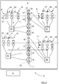
- the antenna arrangement 3 comprises at least one transmitter array antenna 7 and at least two receiver antennas 24, 25, 26; 27, 28, 29; 30, 31, 32; 33, 34, 35 where each receiver antenna 24, 25, 26; 27, 28, 29; 30, 31, 32; 33, 34, 35 comprises a plurality of series fed antenna elements 22, 23 formed in a vertically extending column, in this example there are twelve receiver antennas 24, 25, 26; 27, 28, 29; 30, 31, 32; 33, 34, 35 each comprising two antenna elements 22, 23, shown in Figure 3 as patch antenna elements.
- the receiver antennas 24, 25, 26; 27, 28, 29; 30, 31, 32; 33, 34, 35 form at least one set 8, 9, 10, 11 of receiver antennas with at least two receiver antennas 24, 25, 26; 27, 28, 29; 30, 31, 32; 33, 34, 35 each.
- At least two receiver antennas 24, 25, 26; 27, 28, 29; 30, 31, 32; 33, 34, 35 in at least one set 8, 9, 10, 11 are horizontally spaced a, b, c, d from each other by means of corresponding receiver antenna horizontal distances a, b, c, d.
- the receiver antennas 24, 25, 26 are spaced by a first receiver antenna horizontal distance a
- the receiver antennas 27, 28, 29 are spaced by a second receiver antenna horizontal distance b
- in a third set 10 the receiver antennas 30, 31, 32 are spaced by a third receiver antenna horizontal distance c
- the receiver antennas 33, 34, 35 are spaced by a fourth receiver antenna horizontal distance d.
- the spacings, the receiver antenna horizontal distances, within a set is here shown to be the same, but can of course be different.
- the different receiver antenna horizontal distances a, b, c, d can be equal, or, alternatively, one or more can be mutually different.
- the transmitter array antenna 7 comprises at least two sub-antennas 12, 13, 14, 15, 16, 17, 18, 19 that are vertically spaced from each other, where each sub-antenna 12, 13, 14, 15, 16, 17, 18, 19 comprises at least one antenna element 20, 21 (only indicated for one sub-antenna for reasons of clarity).
- each sub-antenna 12, 13, 14, 15, 16, 17, 18, 19 comprises at least one antenna element 20, 21 (only indicated for one sub-antenna for reasons of clarity).
- the sub-antennas 12, 13, 14, 15, 16, 17, 18, 19 are symmetrically arranged along a vertically extending symmetry line 52.
- each sub-antenna 12, 13, 14, 15, 16, 17, 18, 19 is connected to the transceiver arrangement 4a, 4b, 4c, 4d that is adapted to feed the corresponding sub-antenna 12, 13, 14, 15, 16, 17, 18, 19 with a controllable phase, such that each transmitter array antenna 7 is adapted to provide a transmitter antenna beam 36, 36 1 , 36 2 that is controllable in an elevation direction ⁇ 1 , ⁇ 2 .
- the elevation direction is defined as an elevation angle running between a reference such as a horizontal level 41 and a main pointing direction 40 1 , 40 2 .
- the transmitter antenna beam 36 1 , 36 2 can be directed in several elevation angles ⁇ 1 , ⁇ 2 .
- a first transmitter antenna beam 36 1 is directed in a first main pointing direction 40 1 at a first elevation angle ⁇ 1 and is directed towards a pedestrian 48.
- a second transmitter antenna beam 36 2 is some time later directed in a second main pointing direction 40 2 at a second elevation angle ⁇ 2 and is steered towards a bridge 49.
- the transmitter antenna beam 36 can be directed in a plurality of elevation angles, both point-wise and in a continuous scanning manner, searching for target objects.
- the transceiver arrangement 4a, 4b, 4c, 4d comprises separate transceiver units, in this example a first transceiver unit 4a, a second transceiver unit 4b, a third transceiver unit 4c and a fourth transceiver unit 4d.
- the transmitter array antenna 7 and/or the receiver antennas 24, 25, 26; 27, 28, 29; 30, 31, 32; 33, 34, 35 are integrated into the transceiver arrangement (4a, 4b 4c, 4) may according to some further aspects be integrated into the transceiver units 4a, 4b 4c, 4d, or may at least partly be separate from the antenna arrangement 3.
- a first sub-antenna 12 and a second sub-antenna 13 are connected to the first transceiver unit 4a
- a third sub-antenna 14 and a fourth sub-antenna 15 are connected to the second transceiver unit 4b
- a fifth sub-antenna 16 and a sixth sub-antenna 17 are connected to the third transceiver unit 4c
- a seventh sub-antenna 18 and an eighth sub-antenna 19 are connected to the fourth transceiver unit 4d.
- each receiver antenna 24, 25, 26; 27, 28, 29; 30, 31, 32; 33, 34, 35 is connected to the transceiver arrangement 4a, 4b, 4c, 4d, where each receiver antenna 24, 25, 26; 27, 28, 29; 30, 31, 32; 33, 34, 35 is adapted to provide a receiver antenna beam 37 that has a main pointing direction 38 as illustrated in Figure 6 .
- the receiver antennas 24, 25, 26; 27, 28, 29; 30, 31, 32; 33, 34, 35 are connected to the transceiver units 4a, 4b, 4c, 4d that are comprised in the transceiver arrangement 4a, 4b, 4c, 4d.
- first set 8 is connected to the first transceiver unit 4a
- second set 9 is connected to the second transceiver unit 4b
- third set 10 is connected to the third transceiver unit 4c
- fourth set 11 is connected to the fourth transceiver unit 4d.
- the receiver antenna horizontal distances a, b, c, d can be the same, alternatively one or more can be mutually different.
- the horizontal distance between at least two receiver antennas 24, 25, 26 in at least one set 8' can be separated by mutually different receiver antenna horizontal distances a, a'.
- both antenna horizontal distances a, a' exceed a half wavelength, 0.5 ⁇ r , where ⁇ r is a wavelength corresponding to a received signal center frequency, or a receiver antenna design center frequency. In this way, such a set 8' constitutes a sparse receiver array antenna.
- At least two receiver antennas 27, 29; 28 in at least one set 9' are vertically spaced h from each other by means of a corresponding receiver antenna vertical distance h, as illustrated for the second set 9'.
- a receiver antenna vertical distance h thus vertically separates at least one receiver antenna 28 from the other receiver antennas 27, 29.
- the antenna arrangement 3 comprises at least two sets 8, 9; 10, 11; 8', 9'; 10', 11' that are horizontally spaced L, L', L" from each other by means of a corresponding horizontal set distance L, L', L".
- this is illustrated for the first set 8 and the second set 9 that are horizontally separated by a first horizontal set distance L, and where the third set 10 and the fourth set 11 also are horizontally separated by the first horizontal set distance L.
- first set 8' and the second set 9' are horizontally separated by a second horizontal set distance L' and the third set 10' and the fourth set 11' are horizontally separated by a third horizontal set distance L", where the second horizontal set distance L' and the third horizontal set distance L" are mutually different.
- the antenna arrangement 3 comprises at least two sets of receiver antennas 9, 11; 10', 11' that are vertically spaced H, H' from each other by means of a corresponding vertical set distance H, H'.
- This is illustrated in Figure 3 , where the first set 8 and the second set 9 share the same vertical position while being horizontally separated by the first horizontal set distance L, and where the third set 10 and the fourth set 11 share the same vertical position while being horizontally separated by the first horizontal set distance L.
- the first set 8 and the second set 9, and on the other hand, the third set 10 and the fourth set 11 are separated by a first vertical set distance H.
- the sets 8, 9, 10, 11; 8', 9', 10', 11' and their receiver antennas can be distributed in any suitable manner.
- This enables different types of receiver antenna beams 37 to be formed, and also enables the processing unit 6 to determine elevation of the received signal, in addition to the transmitter antenna beam 36.
- This is beneficial in the case where the transmitter antenna beam 36 has sidelobes that for example are about 15dB below the main beam. This means that the areas outside the main beam will not be entirely masked and strong reflectors at other elevation angles will still come through.
- elevation info derived by means of the receiver antenna beams 37 may help to steer the transmitter antenna beam 36 to deliver an optimized range performance.
- the transmitter array antenna 7 has been described to be a linear array antenna with linearly arranged antenna elements 20, 21, forming sub-antennas 12, 13, 14, 15, 16, 17, 18, 19 in one dimension.
- transmitter array antennas are possible, and an example of an alternative transmitter array antenna 107 is shown in Figure 5 .
- the transmitter array antenna 107 and the transceiver arrangement 4a, 4b, 4c, 4d are shown, not the whole antenna arrangement.
- the alternative transmitter array antenna 107 presented here is comprised in an antenna arrangement with receiver antennas of the types discussed above.
- sub-antennas 112, 113, 114, 115, 116, 117, 118, 119 that are vertically spaced from each other, where there are different numbers of antenna elements 120, 121, 122, 123 (only indicated for one sub-antenna 113 for reasons of clarity) in different sub-antennas 112, 113, 114, 115, 116, 117, 118, 119.
- first sub-antenna 112 and eighth sub-antenna 119 there are two vertically stacked antenna elements, each sub-antenna 112, 119 forming a one-dimensional 1x2 (columns x rows) array.
- second sub-antenna 113, third sub-antenna 114, sixth sub-antenna 117 and seventh sub-antenna 118 there are two vertically stacked antenna elements in two columns, each sub-antenna forming a two-dimensional 2x2 array.
- fourth sub-antenna 115 and fifth sub-antenna 116 there are two vertically stacked antenna elements in three columns, each sub-antenna forming a two-dimensional 3x2 array.
- the two-dimensional sub-antenna arrays that are comprised in the transmitter array antenna 107 can have any suitable configuration, the one presented above only being one example among many possibilities.
- at least one transmitter array antenna 107 comprises at least one sub-antenna 113, 114, 115, 116, 117, 118 with at least two horizontally spaced antenna elements 120, 121; 122, 123.
- the antenna elements 120, 121, 122, 123 in each sub-antenna 113, 114, 115, 116, 117, 118 are fed in phase.
- Each sub-antenna 112, 113, 114, 115, 116, 117, 118, 119 is connected to the transceiver arrangement 4a, 4b, 4c, 4d as described previously, where the transceiver arrangement 4a, 4b, 4c, 4d is adapted to feed the corresponding sub-antenna 112, 113, 114, 115, 116, 117, 118, 119 with a controllable phase, such that the transmitter array antenna 107 is adapted to provide a transmitter antenna beam 36, 36 1 , 36 2 that is controllable in an elevation direction ⁇ 1 , ⁇ 2 as shown in Figure 2 , in the same manner as described previously with reference to Figure 2-4 .
- the transceiver arrangement 4a, 4b, 4c, 4d is adapted to feed the sub-antennas 12, 13, 14, 15, 16, 17, 18, 19; 112, 113, 114, 115, 116, 117, 118, 119 with a controllable signal amplitude.
- the transceiver arrangement 4a, 4b, 4c, 4d is adapted to feed at least one sub-antenna 12, 13, 14, 15, 16, 17, 18, 19; 112, 113, 114, 115, 116, 117, 118, 119 with a signal amplitude that is zero.
- the electrical size of the transmitter array antenna 7, 107 can be changed which will provide flexibility in usage.
- E.g. having just one, or a few, sub-antennas 12, 13, 14, 15, 16, 17, 18, 19; 112, 113, 114, 115, 116, 117, 118, 119 fed with a signal amplitude that exceeds zero will result in a relatively wide elevation beamwidth.
- a mid-sized transmitter antenna beam 36 in elevation for example using four of the eight sub-antennas 12, 13, 14, 15, 16, 17, 18, 19; 112, 113, 114, 115, 116, 117, 118, 119, could sometimes be preferable, e.g. when just starting out and not being sure that the transmitter antenna beam 36 is correctly aligned to the horizon, or when driving in hilly terrain, or in environments where is desired to obtain knowledge about over-head such as low bridges.
- Digital control of the amplitude of the signal at the input to each antenna can be lowered to comply with specific country regulations if necessary.
- an irregular transmitter array antenna 107 that comprises at least one sub-antenna 113, 114, 115, 116, 117, 118 with at least two horizontally spaced antenna elements 120, 121; 122, 123
- different antenna patterns can be selected by using only one or a few of the sub-antennas 112, 113, 114, 115, 116, 117, 118, 119, for example a transmitter antenna beam 36 that has a relatively wide azimuth beamwidth, for example an outer sub-antenna 113, or a relatively narrow azimuth beamwidth but with a higher gain, for example a combination of some central sub-antennas 114, 115, 116, 117. Also, such inherent amplitude weighting helps reduce sidelobes in the elevation domain.
- a combination is also conceivable, where for example one sub-antenna is driven isolated from the others, generating a relatively wide beamwidth in elevation while the other sub-antennas are driven together to form a relatively narrow beamwidth, where that beam is controllable in an elevation direction 40 1 , 40 2 .
- At least two sub-antennas 12, 13, 14, 15, 16, 17, 18, 19 are vertically spaced from each other by a vertical sub-antenna distance r, indicated in Figure 3 and Figure 4 , which according to some further aspects lies between 1,3 ⁇ T and 1,7 ⁇ t , where ⁇ T is a wavelength corresponding to a transmitted signal center frequency, or a transmitter antenna design center frequency.
- the processing unit 6 is adapted to receive input regarding a host vehicle inclination relative horizontal ground and to control the transceiver arrangement 4a, 4b, 4c, 4d to feed the corresponding sub-antenna 12, 13, 14, 15, 16, 17, 18, 19 with a certain set of phases and amplitudes in dependence of said input.
- the processing unit 6 may receive input that indicates a preferred transmission beam pattern and/or direction, where such input may be transferred from another control unit such as a safety control unit 50 as indicated in Figure 1 , or another central control unit.
- the input may further indicate a suspicious target object at which the transmitter antenna beam should be focused, while more radar processing resources are diverted towards identifying or validating the presence of the object.
- the processing is either at least partly performed at the processing unit 6 or at another processing unit.
- the vehicle radar sensor unit can be adapted to always seek out the best elevation angle ⁇ 1 , ⁇ 2 for the transmitter antenna beam 36 when driving. Further, the transmitter antenna beam 36 may be scanned up or down for many different elevation angles ⁇ 1 , ⁇ 2 to confirm presence of bridge 49, overhead signs, or to investigate the road surface in more detail, e.g. detect pot-hole or icy road surface.
- the antenna elements are schematically indicated as linear microstrip patch antennas that can form linear patch antenna arrays, but other antenna configurations are of course possible, such as for example dipole antennas or slot antennas. Only a few antenna elements 20, 21 are indicated for reasons of clarity.
- the antenna elements in one or more sub-antennas are fed in phase.
- the feeding line distance between the transceiver arrangement 4a, 4b, 4c, 4d and each corresponding antenna element should be kept at the same length, in this way the antenna performance is maintained consistent over temperature.
- the antenna elements have been illustrated to be of linear single polarization, where such a single polarization can be vertical polarization, horizontal polarization, or slanted 45° polarization. According to some aspects, the antenna elements are instead dual polarized, and the present disclosure is consequently applied to both polarizations. Alternatively, circular polarization is also conceivable.
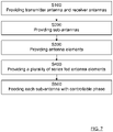
- the present disclosure also relates to a method for a vehicle radar sensor unit 2.
- the method comprises providing S100 at least one transmitter array antenna 7 and at least two receiver antennas 24, 25, 26; 27, 28, 29; 30, 31, 32; 33, 34, 35, and providing S200 at least two sub-antennas 12, 13, 14, 15, 16, 17, 18, 19 that are vertically spaced from each other for each transmitter array antenna 7.
- the method further comprises providing S300 at least one antenna element 20, 21 for each sub-antenna 12, 13, 14, 15, 16, 17, 18, 19, and providing S400 a plurality of series fed antenna elements 22, 23 formed in a column for each receiver antenna 24, 25, 26; 27, 28, 29; 30, 31, 32; 33, 34, 35.
- the method further comprises feeding S500 each sub-antenna 12, 13, 14, 15, 16, 17, 18, 19 with a controllable phase such that each transmitter array antenna 7 is used for providing transmitter antenna beam 36 1 , 36 2 that is controllable in an elevation direction 40 1 , 40 2 .
- the microwave parts of the radar sensor arrangement 3 are assumed to be of a previously known design, and according to some aspects the radar sensor arrangement 3 comprises more parts than shown, and is for example connected to a warning and/or information device comprised in the vehicle 1 in a previously known manner.
- the calculations and determining procedures are performed by the processing unit 6, where the processing unit 6 should be regarded as a processing unit arrangement that is in the form of one unit or several units that either co-operate or handle different tasks more or less independently. In the case of several units, these may be placed adjacent to each other, or in a distributed manner. According to some aspects, the processing unit 6 can be a central processing unit that is shared between several sensor units, and possibly also other vehicle systems.
- the transceiver arrangement 4a, 4b, 4c, 4d may be constituted by one unit or several separate units that can be in the form of MMICs (Monolithic microwave integrated circuits).
- the transceiver arrangement 4a, 4b, 4c, 4d comprises controllable phase shifters and amplifiers which are previously well-known, and can according to some aspects be integrated into the antenna arrangement.
- the number of receiver antennas in each set of receiver antennas may vary from set to set, and the number of antenna elements in each receiver antenna, and their mutual distance, may vary.
- each transmitter array antenna is constituted by one of more sub-antennas that comprise one or more antenna elements each.
- Antenna element separation as well as sub-antenna separation may vary.
- the radar signal can be of any suitable kind, for FMCW chirp signals having any suitable frequency ramp configuration, for example saw-tooth signals and down-ramps where.
- the vehicle radar sensor unit 2 is arranged to transmit any sort of TDM (Time Division Multiplexed) signals, such as for example FMCW signals.
- TDM Time Division Multiplexed
- the vehicle 1 comprises a safety control unit 50 and safety means 51, for example an emergency braking system and/or an alarm signal device.
- the safety control unit 50 is arranged to control the safety means 51 in dependence of input from the radar sensor unit 2. Such input may be input via the processing unit 6.
- sub-antennas and sets of antennas are spaced by defined distances and spacings, these distances and spacings are measured between corresponding phase centers.
- the processing unit 6 can be a central processing unit that is shared between several sensor units, and possibly also other vehicle systems.
- a resulting receiver antenna beam pattern is determined by the attributes of the receiver antennas, which have relatively wide azimuth patterns.
- Relatively narrow azimuth beams are created by means of digital signal processing, such as digital beamforming, which can be performed by the processing unit 6 or any other suitable processing unit.
- digital signal processing such as digital beamforming
- This enables the direction to a target object to be determined in the form of one or more detections, such that target objects of particular attention and arrival direction can be determined in previously well-known ways, for example using FFT/Bartlett based beamforming or a super-resolution technique such as MUSIC (MUltiple SIgnal Classification) or Capon.
- the parameters making up the transmission beam for example the present elevation angle ⁇ 1 , ⁇ 2 , may be updated as a result of the information contained within the one or more detections.
- the transceiver arrangement 4a, 4b, 4c, 4d can be shared between the at least one transmitter array antenna 7 and the at least two receiver antennas 24, 25, 26; 27, 28, 29; 30, 31, 32; 33, 34, 35.
Landscapes
- Engineering & Computer Science (AREA)
- Radar, Positioning & Navigation (AREA)
- Remote Sensing (AREA)
- Physics & Mathematics (AREA)
- Computer Networks & Wireless Communication (AREA)
- General Physics & Mathematics (AREA)
- Electromagnetism (AREA)
- Computer Security & Cryptography (AREA)
- Microelectronics & Electronic Packaging (AREA)
- Radar Systems Or Details Thereof (AREA)
- Variable-Direction Aerials And Aerial Arrays (AREA)
Priority Applications (4)
| Application Number | Priority Date | Filing Date | Title |
|---|---|---|---|
| EP21175664.8A EP4096020A1 (de) | 2021-05-25 | 2021-05-25 | Fahrzeugradarsensoreinheit mit erhöhter vertikaler auflösung |
| US18/560,758 US12562465B2 (en) | 2021-05-25 | 2022-05-20 | Vehicle radar sensor unit with increased vertical resolution |
| PCT/EP2022/063741 WO2022248357A1 (en) | 2021-05-25 | 2022-05-20 | Vehicle radar sensor unit with increased vertical resolution |
| CN202280032181.9A CN117256078A (zh) | 2021-05-25 | 2022-05-20 | 具有改善的竖直分辨率的车辆雷达传感器单元 |
Applications Claiming Priority (1)
| Application Number | Priority Date | Filing Date | Title |
|---|---|---|---|
| EP21175664.8A EP4096020A1 (de) | 2021-05-25 | 2021-05-25 | Fahrzeugradarsensoreinheit mit erhöhter vertikaler auflösung |
Publications (1)
| Publication Number | Publication Date |
|---|---|
| EP4096020A1 true EP4096020A1 (de) | 2022-11-30 |
Family
ID=76137895
Family Applications (1)
| Application Number | Title | Priority Date | Filing Date |
|---|---|---|---|
| EP21175664.8A Pending EP4096020A1 (de) | 2021-05-25 | 2021-05-25 | Fahrzeugradarsensoreinheit mit erhöhter vertikaler auflösung |
Country Status (4)
| Country | Link |
|---|---|
| US (1) | US12562465B2 (de) |
| EP (1) | EP4096020A1 (de) |
| CN (1) | CN117256078A (de) |
| WO (1) | WO2022248357A1 (de) |
Cited By (1)
| Publication number | Priority date | Publication date | Assignee | Title |
|---|---|---|---|---|
| EP4439122A1 (de) * | 2023-03-29 | 2024-10-02 | Magna Electronics Sweden AB | Fahrzeugradarsystem mit einer ersten antennenanordnung und einer zweiten antennenanordnung, die von der ersten antennenanordnung getrennt ist |
Families Citing this family (5)
| Publication number | Priority date | Publication date | Assignee | Title |
|---|---|---|---|---|
| WO2023092474A1 (zh) * | 2021-11-26 | 2023-06-01 | 华为技术有限公司 | 一种天线、探测装置和终端 |
| EP4469825A4 (de) * | 2022-03-09 | 2026-01-21 | Sensata Technologies Inc | Antenne mit breitem sichtfeld zur blindpunktdetektion |
| EP4303608A1 (de) * | 2022-07-05 | 2024-01-10 | Aptiv Technologies Limited | Radarsystem für kraftfahrzeuganwendungen |
| EP4303610A1 (de) * | 2022-07-06 | 2024-01-10 | Aptiv Technologies Limited | Radarsystem für kraftfahrzeuganwendungen |
| US20240319327A1 (en) * | 2023-03-21 | 2024-09-26 | Bendix Commercial Vehicle Systems Llc | Radar Cover for a Vehicle Radar System |
Citations (4)
| Publication number | Priority date | Publication date | Assignee | Title |
|---|---|---|---|---|
| US20150226838A1 (en) * | 2014-02-12 | 2015-08-13 | Fujitsu Ten Limited | Radar apparatus |
| US20180156891A1 (en) * | 2016-12-05 | 2018-06-07 | Echodyne Corp | Antenna subsystem with analog beam-steering transmit array and digital beam-forming receive array |
| US20200284901A1 (en) * | 2019-01-23 | 2020-09-10 | The Government Of The United States Of America, As Represented By The Secretary Of The Navy | Millimeter-wave radar for unmanned aerial vehicle swarming, tracking, and collision avoidance |
| US20200343626A1 (en) * | 2019-04-26 | 2020-10-29 | Infineon Technologies Ag | Rf devices including conformal antennas and methods for manufacturing thereof |
Family Cites Families (10)
| Publication number | Priority date | Publication date | Assignee | Title |
|---|---|---|---|---|
| US5115245A (en) * | 1990-09-04 | 1992-05-19 | Hughes Aircraft Company | Single substrate microwave radar transceiver including flip-chip integrated circuits |
| JP2009265007A (ja) * | 2008-04-28 | 2009-11-12 | Hitachi Ltd | 移動体用レーダ及び平面アンテナ |
| EP3329295B1 (de) * | 2015-07-29 | 2021-08-18 | QUALCOMM Incorporated | Winkel- und positionserfassung mit arrays von antennen |
| EP3413077B1 (de) * | 2017-06-09 | 2020-02-19 | Veoneer Sweden AB | Verbesserte vertikale objekterkennung für ein kraftfahrzeug-radarsystem |
| US11585890B2 (en) * | 2018-04-02 | 2023-02-21 | Maxlinear, Inc. | Phased array automotive radar |
| DE102018207718A1 (de) * | 2018-05-17 | 2019-11-21 | Robert Bosch Gmbh | Verfahren zur Phasenkalibrierung von Hochfrequenzbausteinen eines Radarsensors |
| KR102232075B1 (ko) * | 2018-06-27 | 2021-03-25 | 주식회사 비트센싱 | 레이더 장치 및 레이더 장치에 이용되는 안테나 장치 |
| JP6694027B2 (ja) * | 2018-08-29 | 2020-05-13 | パナソニック株式会社 | レーダ装置 |
| KR102539927B1 (ko) * | 2018-12-20 | 2023-06-08 | 주식회사 에이치엘클레무브 | 자동차 레이더용 어레이 안테나 구조 및 그 배치 방법 |
| US12695210B2 (en) * | 2020-02-20 | 2026-07-28 | Bdcm A2 Llc | Modular, multi-channel beamformer front-end integrated circuits for millimeter wave applications |
-
2021
- 2021-05-25 EP EP21175664.8A patent/EP4096020A1/de active Pending
-
2022
- 2022-05-20 CN CN202280032181.9A patent/CN117256078A/zh active Pending
- 2022-05-20 US US18/560,758 patent/US12562465B2/en active Active
- 2022-05-20 WO PCT/EP2022/063741 patent/WO2022248357A1/en not_active Ceased
Patent Citations (4)
| Publication number | Priority date | Publication date | Assignee | Title |
|---|---|---|---|---|
| US20150226838A1 (en) * | 2014-02-12 | 2015-08-13 | Fujitsu Ten Limited | Radar apparatus |
| US20180156891A1 (en) * | 2016-12-05 | 2018-06-07 | Echodyne Corp | Antenna subsystem with analog beam-steering transmit array and digital beam-forming receive array |
| US20200284901A1 (en) * | 2019-01-23 | 2020-09-10 | The Government Of The United States Of America, As Represented By The Secretary Of The Navy | Millimeter-wave radar for unmanned aerial vehicle swarming, tracking, and collision avoidance |
| US20200343626A1 (en) * | 2019-04-26 | 2020-10-29 | Infineon Technologies Ag | Rf devices including conformal antennas and methods for manufacturing thereof |
Cited By (2)
| Publication number | Priority date | Publication date | Assignee | Title |
|---|---|---|---|---|
| EP4439122A1 (de) * | 2023-03-29 | 2024-10-02 | Magna Electronics Sweden AB | Fahrzeugradarsystem mit einer ersten antennenanordnung und einer zweiten antennenanordnung, die von der ersten antennenanordnung getrennt ist |
| WO2024200221A1 (en) * | 2023-03-29 | 2024-10-03 | Magna Electronics Sweden Ab | A vehicle radar system comprising a first antenna arrangement and a second antenna arrangement, separate from the first antenna arrangement |
Also Published As
| Publication number | Publication date |
|---|---|
| US20240222853A1 (en) | 2024-07-04 |
| WO2022248357A1 (en) | 2022-12-01 |
| CN117256078A (zh) | 2023-12-19 |
| US12562465B2 (en) | 2026-02-24 |
Similar Documents
| Publication | Publication Date | Title |
|---|---|---|
| US12562465B2 (en) | Vehicle radar sensor unit with increased vertical resolution | |
| US10197671B2 (en) | Virtual radar configuration for 2D array | |
| US10620305B2 (en) | Multibeam FMCW radar, in particular for automobile | |
| US10573959B2 (en) | Vehicle radar system using shaped antenna patterns | |
| EP3156817B1 (de) | Mimo-radarantenne zur höhenwinkeldetektion | |
| EP3545334B1 (de) | Antennensubsystem mit analogem strahlschwenkendem übertragungsarray und digitalem strahlformendem empfangsarray | |
| US7474262B2 (en) | Digital beamforming for an electronically scanned radar system | |
| US9541639B2 (en) | MIMO antenna with elevation detection | |
| EP1324068A2 (de) | Mehrstrahl-Radarsystem | |
| US12405369B2 (en) | Radar imaging method, and radar implementing such a method | |
| US20090021429A1 (en) | Low cost short range radar | |
| JP2014055957A (ja) | フェーズド・アレイ・レーダによる3d短距離検出方法 | |
| WO2022229386A1 (en) | Mimo radar using a frequency scanning antenna | |
| US11251542B2 (en) | Antenna array for a radar sensor | |
| US11843162B2 (en) | MIMO radar system for an aerial vehicle | |
| EP3780274B1 (de) | Gruppenantennenanordnung | |
| US8482454B2 (en) | Monostatic multi-beam radar sensor, as well as method | |
| KR102394992B1 (ko) | 안테나 장치 및 이를 포함하는 피아 식별 시스템 | |
| EP0141886B1 (de) | Monopulserfassungssysteme | |
| EP0015163A1 (de) | Radaranlage mit räumlich getrennt angeordneten Sende- und Empfangsantennen | |
| Bradsell | Phased arrays in radar | |
| EP4607233A1 (de) | Radarantenne, signalhandhabungskomponente und verfahren zur radardetektion eines objekts | |
| KR102391795B1 (ko) | 안테나 장치 및 이를 포함하는 피아 식별 시스템 | |
| EP4303610A1 (de) | Radarsystem für kraftfahrzeuganwendungen |
Legal Events
| Date | Code | Title | Description |
|---|---|---|---|
| PUAI | Public reference made under article 153(3) epc to a published international application that has entered the european phase |
Free format text: ORIGINAL CODE: 0009012 |
|
| STAA | Information on the status of an ep patent application or granted ep patent |
Free format text: STATUS: THE APPLICATION HAS BEEN PUBLISHED |
|
| AK | Designated contracting states |
Kind code of ref document: A1 Designated state(s): AL AT BE BG CH CY CZ DE DK EE ES FI FR GB GR HR HU IE IS IT LI LT LU LV MC MK MT NL NO PL PT RO RS SE SI SK SM TR |
|
| STAA | Information on the status of an ep patent application or granted ep patent |
Free format text: STATUS: REQUEST FOR EXAMINATION WAS MADE |
|
| 17P | Request for examination filed |
Effective date: 20230525 |
|
| RBV | Designated contracting states (corrected) |
Designated state(s): AL AT BE BG CH CY CZ DE DK EE ES FI FR GB GR HR HU IE IS IT LI LT LU LV MC MK MT NL NO PL PT RO RS SE SI SK SM TR |
|
| RAP3 | Party data changed (applicant data changed or rights of an application transferred) |
Owner name: MAGNA ELECTRONICS SWEDEN AB |
|
| RAP3 | Party data changed (applicant data changed or rights of an application transferred) |
Owner name: MAGNA ELECTRONICS SWEDEN AB |
|
| STAA | Information on the status of an ep patent application or granted ep patent |
Free format text: STATUS: EXAMINATION IS IN PROGRESS |
|
| 17Q | First examination report despatched |
Effective date: 20251002 |