EP3330040A1 - Outil pour chemise de combustion - Google Patents
Outil pour chemise de combustion Download PDFInfo
- Publication number
- EP3330040A1 EP3330040A1 EP17204478.6A EP17204478A EP3330040A1 EP 3330040 A1 EP3330040 A1 EP 3330040A1 EP 17204478 A EP17204478 A EP 17204478A EP 3330040 A1 EP3330040 A1 EP 3330040A1
- Authority
- EP
- European Patent Office
- Prior art keywords
- liner
- combustion
- tool
- mounting frame
- positioning member
- Prior art date
- Legal status (The legal status is an assumption and is not a legal conclusion. Google has not performed a legal analysis and makes no representation as to the accuracy of the status listed.)
- Granted
Links
Images




Classifications
-
- F—MECHANICAL ENGINEERING; LIGHTING; HEATING; WEAPONS; BLASTING
- F01—MACHINES OR ENGINES IN GENERAL; ENGINE PLANTS IN GENERAL; STEAM ENGINES
- F01D—NON-POSITIVE DISPLACEMENT MACHINES OR ENGINES, e.g. STEAM TURBINES
- F01D25/00—Component parts, details, or accessories, not provided for in, or of interest apart from, other groups
- F01D25/28—Supporting or mounting arrangements, e.g. for turbine casing
- F01D25/285—Temporary support structures, e.g. for testing, assembling, installing, repairing; Assembly methods using such structures
-
- B—PERFORMING OPERATIONS; TRANSPORTING
- B25—HAND TOOLS; PORTABLE POWER-DRIVEN TOOLS; MANIPULATORS
- B25B—TOOLS OR BENCH DEVICES NOT OTHERWISE PROVIDED FOR, FOR FASTENING, CONNECTING, DISENGAGING, OR HOLDING
- B25B27/00—Hand tools, specially adapted for fitting together or separating parts or objects whether or not involving some deformation, not otherwise provided for
- B25B27/02—Hand tools, specially adapted for fitting together or separating parts or objects whether or not involving some deformation, not otherwise provided for for connecting objects by press fit or detaching same
- B25B27/023—Hand tools, specially adapted for fitting together or separating parts or objects whether or not involving some deformation, not otherwise provided for for connecting objects by press fit or detaching same using screws
-
- B—PERFORMING OPERATIONS; TRANSPORTING
- B25—HAND TOOLS; PORTABLE POWER-DRIVEN TOOLS; MANIPULATORS
- B25B—TOOLS OR BENCH DEVICES NOT OTHERWISE PROVIDED FOR, FOR FASTENING, CONNECTING, DISENGAGING, OR HOLDING
- B25B27/00—Hand tools, specially adapted for fitting together or separating parts or objects whether or not involving some deformation, not otherwise provided for
- B25B27/02—Hand tools, specially adapted for fitting together or separating parts or objects whether or not involving some deformation, not otherwise provided for for connecting objects by press fit or detaching same
- B25B27/06—Hand tools, specially adapted for fitting together or separating parts or objects whether or not involving some deformation, not otherwise provided for for connecting objects by press fit or detaching same inserting or withdrawing sleeves or bearing races
- B25B27/062—Hand tools, specially adapted for fitting together or separating parts or objects whether or not involving some deformation, not otherwise provided for for connecting objects by press fit or detaching same inserting or withdrawing sleeves or bearing races using screws
-
- F—MECHANICAL ENGINEERING; LIGHTING; HEATING; WEAPONS; BLASTING
- F23—COMBUSTION APPARATUS; COMBUSTION PROCESSES
- F23R—GENERATING COMBUSTION PRODUCTS OF HIGH PRESSURE OR HIGH VELOCITY, e.g. GAS-TURBINE COMBUSTION CHAMBERS
- F23R3/00—Continuous combustion chambers using liquid or gaseous fuel
- F23R3/002—Wall structures
-
- F—MECHANICAL ENGINEERING; LIGHTING; HEATING; WEAPONS; BLASTING
- F23—COMBUSTION APPARATUS; COMBUSTION PROCESSES
- F23R—GENERATING COMBUSTION PRODUCTS OF HIGH PRESSURE OR HIGH VELOCITY, e.g. GAS-TURBINE COMBUSTION CHAMBERS
- F23R3/00—Continuous combustion chambers using liquid or gaseous fuel
- F23R3/42—Continuous combustion chambers using liquid or gaseous fuel characterised by the arrangement or form of the flame tubes or combustion chambers
- F23R3/44—Combustion chambers comprising a single tubular flame tube within a tubular casing
-
- F—MECHANICAL ENGINEERING; LIGHTING; HEATING; WEAPONS; BLASTING
- F05—INDEXING SCHEMES RELATING TO ENGINES OR PUMPS IN VARIOUS SUBCLASSES OF CLASSES F01-F04
- F05D—INDEXING SCHEME FOR ASPECTS RELATING TO NON-POSITIVE-DISPLACEMENT MACHINES OR ENGINES, GAS-TURBINES OR JET-PROPULSION PLANTS
- F05D2230/00—Manufacture
- F05D2230/70—Disassembly methods
-
- F—MECHANICAL ENGINEERING; LIGHTING; HEATING; WEAPONS; BLASTING
- F05—INDEXING SCHEMES RELATING TO ENGINES OR PUMPS IN VARIOUS SUBCLASSES OF CLASSES F01-F04
- F05D—INDEXING SCHEME FOR ASPECTS RELATING TO NON-POSITIVE-DISPLACEMENT MACHINES OR ENGINES, GAS-TURBINES OR JET-PROPULSION PLANTS
- F05D2260/00—Function
- F05D2260/83—Testing, e.g. methods, components or tools therefor
-
- F—MECHANICAL ENGINEERING; LIGHTING; HEATING; WEAPONS; BLASTING
- F23—COMBUSTION APPARATUS; COMBUSTION PROCESSES
- F23R—GENERATING COMBUSTION PRODUCTS OF HIGH PRESSURE OR HIGH VELOCITY, e.g. GAS-TURBINE COMBUSTION CHAMBERS
- F23R2900/00—Special features of, or arrangements for continuous combustion chambers; Combustion processes therefor
- F23R2900/00017—Assembling combustion chamber liners or subparts
Definitions
- the disclosure relates to tools for installing and removing combustion liners of combustors.
- Gas turbines typically include a compressor section, a combustion section, and a turbine section.
- the compressor section pressurizes air flowing into the turbine.
- the combustion section receives the pressurized air, mixes it with fuel, and combusts the mixture.
- the turbine section receives the combustion flow from the combustion section to drive the turbine and generate power.
- the combustion section generally includes one or more combustors disposed around the axis of the gas turbine. Each of the combustors includes a combustion chamber defined by a combustion liner. Combustion occurs in the space within the combustion liner and the combustion liner is generally coated with ceramic materials or other combustion resistant materials.
- Combustion liners are routinely removed during combustor maintenance and repair.
- a significant amount of force can be required to install, remove, and/or re-install the combustion liner within a combustor to overcome the friction at the interface between the combustion liner and the transition piece.
- a seal is typically disposed at this interface that must be compressed in order to allow the combustion liner to insert into the transition piece. This sometimes requires several hundred pounds of axial installation force and may require a similar magnitude of force for removal.
- Various approaches have been used for generating this installation force, including manually operated hammers, threaded blocks that moveably engage the combustion liner, and others. Manually hammering and various configurations for engaging the combustion liner can damage combustion liners, particularly ceramic coatings, and may provide less reliable positioning of the combustion liner.
- a first aspect of this disclosure provides a combustion liner tool.
- the tool comprises a mounting frame, a positioning member, and an axial positioning mechanism.
- the mounting frame has a central frame axis, a plurality of distal end positions distributed circumferentially at a casing distance from the central member axis, and at least one fastener positioned at the plurality of distal end positions.
- the positioning member has a central member axis, at least one pushing surface distributed circumferentially at a first sleeve distance from the central member axis, and a plurality of pulling surfaces distributed circumferentially at a second sleeve distance from the central member axis.
- the axial positioning mechanism engages the mounting frame proximate the central frame axis and the positioning member proximate the central member axis.
- the axial positioning mechanism incrementally positions the positioning member relative to the mounting frame by adjusting a positioning distance between the mounting frame and the positioning member.
- a second aspect of the disclosure provides a tool for installing and removing a combustion liner inside a combustion casing.
- the tool comprises a mounting frame, a positioning member, and an axial positioning mechanism.
- the mounting frame has at least one fastener positioned among a plurality of distal end positions distributed circumferentially around an end casing surface of the combustion casing.
- the at least one fastener removably attaches the mounting frame to the combustion casing.
- the positioning member has at least one pushing surface distributed circumferentially around an end liner surface of the combustion liner and a plurality of pulling surfaces distributed circumferentially around an exterior liner surface of the combustion liner.
- the axial positioning mechanism engages the mounting frame and the positioning member along a common axis. The axial positioning mechanism incrementally positions the positioning member relative to the mounting frame by adjusting a positioning distance between the mounting frame and the positioning member.
- a third aspect of the disclosure provides a combustion liner tool.
- the tool comprises a mounting frame, a positioning member, and an axial positioning mechanism.
- the mounting frame has a first end distal end position with a first fastener and a second distal end position with a second fastener.
- the positioning member has a central hub and at least three member arms distributed circumferentially around the central hub. Each of the at least three member arms has a pushing surface and a pulling surface.
- the axial positioning mechanism engages the mounting frame and the positioning member along a common axis. The axial positioning mechanism incrementally positions the positioning member relative to the mounting frame by adjusting a positioning distance between the mounting frame and the positioning member.
- aspects of the disclosure may be implemented through a tool comprised of a plurality of components made of aluminum, tool-grade medium-carbon steel, titanium, or similar metals.
- different components may be made of different materials.
- Some components may be composed of or coated with other non-metal materials, such as plastic or rubber for pads, pusher blocks, handles, stop hooks, etc.
- some components may be forged, cast, machined, printed, or some combination thereof as a single piece and/or welded, bonded, or otherwise permanently joined into a single component.
- one or more components may be removably attached to other components with bolts (or other fasteners), mating threads, interference fit, spring pegs, or other mechanical attachments. More specifically, some components may be made in varying dimensions or other interchangeable features to enable the tool to be customized to a specific application, such as machines of varying sizes and the dimensions of the combustion cases and combustion liners.
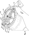
- FIG. 1 and FIG. 2 an example combustion liner tool 100 according to various embodiments is depicted.
- tool 100 is composed of a mounting frame 110, a positioning member 150, and an axial positioning mechanism 200.
- Mounting frame 110 may include one or more structural members for spanning an opening in a combustor into which a combustion liner is inserted.
- Mounting frame 110 may transect the central axis of the generally cylindrical combustion liner and combustion chamber of the combustor and extend to a mounting surface on the combustion casing.
- Mounting frame 110 may include a plurality of fasteners 130, 140 for removably attaching to the combustion casing.
- the combustion casing may have a flat annular flange surface surrounding the opening for the combustion liner for receiving a combustion cover assembly.
- the flange surface may include a plurality of holes for attaching the combustion cover assembly that may provide attachment points for fasteners attached to mounting frame 110 when tool 100 is in use (and the cover is not).
- Positioning member 150 may include one or more structural members for holding and positioning the combustion liner for installation and removal.
- Positioning member 150 may include a plurality of member arms 160, 170, 180 each extending from a central hub 152 across and past the outer diameter of the combustion liner.
- Positioning member 150 may include a pushing interface for engaging the distal end surface of the combustion liner and a pulling interface for engaging the liner stops extending from the outer surface of the combustion liner.
- Axial positioning mechanism 200 connects positioning member 150 to mounting frame 110 along the central axis 102 of tool 100, which generally aligns with the central axis of the combustion liner.
- Axial positioning mechanism 200 may operate along an axial adjustment member 210 that may be used to adjust the axial spacing between positioning member 150 and mounting frame 110.
- axial positioning mechanism 200 may be a jack screw with a threaded connection through mounting frame 110 and a fixed rotatable connection to positioning member 150.
- jack screw incrementally adjusts the positioning distance between mounting frame 110 and positioning member 150 such that the combustion liner is moved the same distance relative to the combustion casing and the seal for receiving the downstream end of the combustion liner.
- the environment and use of tool 100 will be further described below with regard to FIGS. 3-5 .
- mounting frame 110 comprises a mounting bar 112 extending laterally and generally perpendicular to central axis 102.
- a central portion 114 traverses central axis 102 and provides a positioning interface 116 with axial positioning mechanism 200. Where central portion 114 defines positioning interface 116 and surrounds central axis 102 may be referred to as the central frame axis.
- Positioning interface 116 may include a threaded interface or other axially adjustable interface for moving axial positioning mechanism 200 along axis 102 through central portion 114. Alternatively, positioning interface 116 may hold mounting frame in a fixed position in the axial direction, while allowing axial positioning mechanism 200 to rotate freely to adjust the relative position of positioning member 150.
- Mounting bar 112 has a length greater than a span distance to traverse the opening in a combustion casing for receiving the combustion liner, whereby the distal ends 118, 120 extend past the opening and overlap a portion of the combustion casing.
- the distance from central axis 102 to an attachment surface of the combustion casing with which tool 100 is compatible may be referred to as the casing distance.
- Mounting bar 112 includes through holes (not visible) proximate distal ends 118, 120 for accommodating fasteners 130, 140.
- mounting bar 112 also defines bar spaces 122, 124 that are through holes that remove unnecessary weight from mounting bar 112 and provide greater visibility through tool 100.
- mounting frame 110 may comprise a plurality of mounting bars or alternate frame shapes for providing more than a single span and two distal ends for overlapping the combustion casing.
- mounting frame 110 could comprise a tripod, cross, or "H" shape and provide 3-4 distal ends or any number of arms may be possible for providing a plurality of distal ends, preferably at regular spacings around the annular surface.
- mounting bar 112 is essentially planar, with distal ends 118, 120 in the same plane as central portion 114.
- central portion 114 may be displaced along central axis 102 to be closer to or farther from the combustion liner by angling or curving mounting bar 112.
- Fasteners 130, 140 may be configured to engage a hole, flange, or other feature of the combustion casing for removably attaching mounting frame 110 to the combustion casing.
- Fasteners 130, 140 may be a mechanical fastener, such as bolts (or other threaded fasteners), pegs/keys, expansion caps, clamps/vices, or other mechanical attachments.
- fasteners 130, 140 may include threaded shafts 132, 142 extending through mounting bar 112 and spacer plates 134, 144 to be threadably coupled to threaded holes in the combustion casing.
- fasteners 130, 140 may include threaded shafts to expansion caps or plugs that can be expanded to provide a resistance fit within holes in the combustion casing.
- fasteners 130, 140 may not be the same type of fastener.
- fastener 130 may be a fastener for preventing both axial and rotational movement of mounting bar 112 (e.g., a threaded fastener) and fastener 140 may be a peg or pin that only prevents rotational movement.
- spacer plates 134, 144 are comprised of a different material than mounting bar 112 and provide a casing interface surface 136, 146 that engages a surface of the combustion casing and has surface characteristics less likely to damage the combustion casing or generate particulates.
- spacer plates 134, 144 are attached to mounting bar 112 with a plurality of mechanical fasteners, such as screws, or otherwise bonded to mounting bar 112.
- fasteners 130, 140 include hand screw handles 138, 148 to assist a user in manually turning threaded shafts 132, 142 to engage and disengage mounting frame 110 to and from the combustion casing.
- positioning member 150 includes central hub 152 surrounding central axis 102 and a plurality of member arms 160, 170, 180 extending laterally from central hub 152 and generally perpendicular to central axis 102.
- Central hub 152 may be an annular hub with a through hole (not visible) for receiving axial positioning mechanism 200 and defining at least a portion of positioning interface 154. Where central hub 152 defines positioning interface 154 and surrounds central axis 102 may be referred to as the central member axis.
- Positioning interface 154 may hold positioning member 150 in a fixed position in the axial direction, while allowing axial positioning mechanism 200 to rotate freely to adjust the relative position of mounting frame 110.
- positioning interface 154 may include a threaded interface or other axially adjustable interface for moving axial positioning mechanism 200 along axis 102 through central hub 152.
- Member arms 160, 170, 180 may be evenly spaced around a circumference of central hub 152 and extend outward to overlap and extend beyond an exterior circumference of the combustion casing. Member arms 160, 170, 180 may extend to a first liner distance corresponding to the distal surface of the upstream end of the combustion liner and past the first liner distance to a second liner distance corresponding to the exterior circumference of the combustion liner, but less than the distance to the exterior edge of the liner stops.
- the portions of member arms 160, 170, 180 generally overlapping the distal surface of the combustion liner may define a pushing surface for engaging the distal surface of the combustion liner to apply a pushing force when pushing the combustion liner into the seal at its downstream end.
- the pushing surface is a portion of pushing pads 162, 172, 182 generally aligned with the distal surface of the combustion liner on combustion liner facing surfaces 166, 176, 186.
- pushing pads 162, 172, 182 may be a plastic, rubber, or other polymer material that is shaped (molded, cut, etc.) and adhered or fastened to liner facing surfaces 166, 176, 186.
- the pushing surface is made from the same materials as member arms 160, 170, 180 and may be continuous with liner facing surfaces 166, 176, 186 and/or include a coated surface thereof.
- member arms 160, 170, 180 may support a continuous annular pushing surface, such as a single pushing ring pad with an attachment point to each of member arms 160, 170, 180.
- liner stop hooks 164, 174, 184 may extend from the distal ends of member arms 160, 170, 180 in the axial direction to align with liner stops on the exterior surface of the combustion liner.
- Liner stop hooks 164, 174, 184 may generally include an extension portion to provide a desired distance or reach from the liner facing surfaces 166, 176, 186 and a hooked portion defining liner stop interface surfaces 168, 178, 188.
- a plurality of liner stops may be positioned circumferentially around the exterior surface of the combustion liner, generally aligned with one another in the axial direction (equidistant from the distal surface of the upstream end).
- combustion liners may have liner stop configurations that are unevenly spaced circumferentially, at different axial distances along the surface, or different shapes or sizes.
- Liner stop hooks 164, 174, 184 may be configured such that they simultaneously engage the plurality of liner stops and may be configured accordingly.
- the extension portions of liner stop hooks 164, 174, 184 may generally be the same length, the hook portions may define liner stop interface surfaces 168, 178, 188 for engaging with similarly shaped and sized liner stops, and member arms 160, 170, 180 may be regularly spaced and in equal number to the liner stops.
- liner stop hooks 164, 174, 184 may be of varying lengths and/or include different circumferential offsets, the hook portions may define liner stop interface surfaces 168, 178, 188 for engaging with differently shaped and sized liner stops, and/or member arms 160, 170, 180 may be spaced to match a different configuration of liner stops.
- liner stop hooks 164, 174, 184 may be in such number, positions, and interface surface configurations to engage at least a portion of liner stops on a variety of different combustion liner configurations sufficient to apply the necessary force for engaging and pulling the combustion liner, but less than all available liner stops.
- Liner stop hooks 164, 174, 184 can be inserted into the gap between the combustion liner and the combustion casing and rotatably engaged to the liner stops.
- a portion of liner stop hooks 164, 174, 184 may extend past the downstream surface of the liner stops and then be rotated under the downstream surface such that when axial positioning mechanism 200 draws positioning member 150 in the upstream direction, liner stop interface surfaces 168, 178, 188 engage the downstream surfaces of the liner stops.
- Liner stop hooks 164, 174, 184 may also engage a lateral (in the direction of the circumference of the combustion liner) surface of the liner stops to assist in positioning liner stop hooks 164, 174, 184.
- liner stop hooks 164, 174, 184 may be inserted in the space between liner stops and then rotated until they contact the liner stops.
- liner stop hooks 164, 174, 184 may include a coating or be composed of a material to reduce the chance of damaging liner stops, exterior surface of the combustion liner, or liner facing surface of the combustion casing, should they come into contact.
- liner stop hooks 164, 174, 184 may be tool steel coated with a polymer coating and attached with fasteners to aluminum member arms 160, 170, 180.
- axial positioning mechanism 200 may movably connect to positioning member 150 at positioning interface 154 and to mounting frame 110 at positioning interface 116.
- axial positioning mechanism 200 may include an axial shaft 202 extending along axis 102 and passing within through holes in positioning member 150 and mounting frame 110.
- Axial positioning mechanism 200 may be any mechanical device or arrangement for adjusting the relative distance between mounting frame 110, which may provide a stable position for tool 100 once attached to the combustion casing, and positioning member 150, which may translate any change in distance between mounting frame 110 and positioning member 150 into movement of the combustion liner.
- axial positioning mechanism 200 may be a jack screw.
- Axial shaft 202 may be a threaded shaft including threads 204 along its length.
- Axial shaft 202 may pass through mounting frame 110 at positioning interface 116, which includes a complementary threaded interface for moving axial shaft 202 through mounting frame 110 based on rotating motion of axial shaft 202.
- a threaded nut may be installed in positioning interface 116 and mounted to mounting bar 112 using a shaped flange with fasteners.
- Axial shaft 202 may also pass through positioning member 150 at positioning interface 154, which includes a non-threaded interface that allows rotation of axial shaft 202 relative to positioning member 150 without changing the fixed axial position of positioning member 150.
- positioning interface 154 may include a pinned foot nut 206 above and a pinned end nut 208 below positioning member 150 that retain the axial position of positioning member 150 while it rotates around an annular bushing that separates the through hole in positioning member 150 from axial shaft 202. It may be desirable to provide some frictional resistance to rotation around the bushing to enable positioning member 150 to be rotated with axial shaft 202 until a greater resistance to rotation is encountered, such as when contact is made with the liner stops in the circumferential direction.
- axial shaft 202 may include a turning interface 210, such as a hand or tool interface.
- turning interface 210 may include an ergonomically shaped hand turning handle or a nut for use with a socket tool (manual or powered).
- Combustion casing 310 includes a plurality of holes 312 into which fasteners 130, 140 may be attached to secure mounting frame 110 to combustion casing 310.
- Combustion liner 350 may include a distal surface 352 at the upstream end that may be engaged by positioning member 150. For example, pushing pad 182 on member arm 180 may engage distal surface 352 to push combustion liner 350 into place.
- Combustion liner 350 may include a plurality of liner stops, such as liner stop 354, that may be engaged by liner stop hooks, such as liner stop hook 184.
- Combustor 20 may include a substantially cylindrical combustion casing 22 secured to a portion of a gas turbine casing 24, such as a compressor discharge casing or a combustion wrapper casing.
- a flange 26 may extend outwardly from an upstream end of combustion casing 22.
- Flange 26 may be configured such that an end cover assembly (not shown) may be secured to combustion casing 22.
- flange 26 may define a plurality of circumferentially spaced flange holes 72 for attaching the end cover assembly to combustion casing 22.
- flange holes 72 may accommodate fasteners from a combustion liner tool, such as combustion liner tool 100, for securing the tool to combustion casing 22.
- Combustor 20 may also include an internal flow sleeve 28 and a combustion liner 30 substantially concentrically arranged within flow sleeve 28. Both flow sleeve 28 and combustion liner 30 may extend, at their downstream ends, to a double walled transition duct, including an impingement sleeve 32 and a transition piece 34 disposed within impingement sleeve 32.
- Impingement sleeve 32 and flow sleeve 28 may be provided with a plurality of air supply holes 36 over a portion of their surfaces, thereby permitting pressurized air from the compressor section to enter the radial space between combustion liner 30 and flow sleeve 28.
- Combustion liner 30 of combustor 20 may define a substantially cylindrical combustion chamber 38, wherein fuel and air are injected and combusted to produce hot gases of combustion.
- Combustion liner 30 may be coupled at its downstream end to transition piece 34 such that combustion liner 30 and transition piece 34 define a flow path for the hot cases of combustion flowing from each combustor 20 to the turbine section of the turbine assembly.
- Transition piece 34 may be coupled to the downstream end of combustion liner 30 with a compression or hula seal 40.
- Hula seal 40 may be disposed at overlapping ends of transition piece 34 and combustion liner 30 to seal the interface between the two components.
- Hula seal 40 may comprise a circumferential metal seal configured to be spring/compression loaded between inner and outer diameters of mating parts.
- Installing and removing combustion liner 30 may comprise applying sufficient force to move the downstream end of combustion liner 30 into and through mating contact with hula seal 40 and, thereby require the necessary force to overcome frictional resistance of the spring/compression load and any interference fit.
- Combustion liner 30 may also include one or more male liner stops 42 that engage one or more female liner stops 44 secured to flow sleeve 28 or combustion casing 22.
- Male liner stops 42 may be adapted to slide into the female liner stops 444 as combustion liner 30 is installed within combustor 20 to indicate the proper installation depth of combustion liner 30 as well as prevent rotation of combustion liner 30 during operation of the turbine.
- Liner stops 42, 44 may ensure proper circumferential alignment of combustion liner 30 within combustor 20.
- Female liner stops 44 may be substantially "U" shaped and male liner stops 42 may be substantially rectangular in cross-section such that the male liner stops 42 slide into and engage the female liner stops 44.
- Other configurations are possible, for example, male liner stops may be a different cross-section or disposed on flow sleeve 28 while the female liner stops may be some complementary shape and disposed on the combustion liner.
- combustion liner 30 when installing combustion liner 30 within combustor 20, combustion liner 30 is initially pushed into combustor 20 by hand. As combustion liner 30 reaches a point where direct hand force limits further installation depth into transition piece 34, a combustion liner tool may be helpful. For example, a significant amount of axial force may be required to compress seal 40 and thereby position combustion liner 30 with respect to transition piece 34. Such axial force may be provided by a combustion liner tool, like tool 100 described above, to ensure that combustion liner 30 is fully installed within combustor 20. Similarly, removal of combustion liner 30 may require a similar but opposite application of axial force to remove combustion liner 30 during maintenance or servicing of combustor 20 and a combustion liner tool may again be helpful.
Landscapes
- Engineering & Computer Science (AREA)
- Mechanical Engineering (AREA)
- General Engineering & Computer Science (AREA)
- Chemical & Material Sciences (AREA)
- Combustion & Propulsion (AREA)
- Portable Nailing Machines And Staplers (AREA)
Applications Claiming Priority (1)
| Application Number | Priority Date | Filing Date | Title |
|---|---|---|---|
| US15/367,863 US10704421B2 (en) | 2016-12-02 | 2016-12-02 | Combustion liner tool |
Publications (2)
| Publication Number | Publication Date |
|---|---|
| EP3330040A1 true EP3330040A1 (fr) | 2018-06-06 |
| EP3330040B1 EP3330040B1 (fr) | 2021-08-11 |
Family
ID=60543387
Family Applications (1)
| Application Number | Title | Priority Date | Filing Date |
|---|---|---|---|
| EP17204478.6A Active EP3330040B1 (fr) | 2016-12-02 | 2017-11-29 | Outil pour chemise de chambre de combustion |
Country Status (3)
| Country | Link |
|---|---|
| US (1) | US10704421B2 (fr) |
| EP (1) | EP3330040B1 (fr) |
| JP (1) | JP7098310B2 (fr) |
Cited By (1)
| Publication number | Priority date | Publication date | Assignee | Title |
|---|---|---|---|---|
| WO2021011195A1 (fr) * | 2019-07-17 | 2021-01-21 | General Electric Company | Ensemble de retenue axiale pour composants de chambre de combustion de moteur à turbine à gaz |
Families Citing this family (7)
| Publication number | Priority date | Publication date | Assignee | Title |
|---|---|---|---|---|
| EP3354985B1 (fr) * | 2017-01-27 | 2020-11-25 | General Electric Company | Appareil et procédé de maintenance de boîte de combustion |
| JP2020001099A (ja) | 2018-06-25 | 2020-01-09 | セイコーエプソン株式会社 | 制御装置、ロボット、及び、ロボットシステム |
| FR3098746B1 (fr) * | 2019-07-17 | 2021-07-30 | Safran Aircraft Engines | Outillage et procede de demontage et de deplacement d’un carter de turbine du type trv d’une turbomachine d’aeronef |
| US11267113B1 (en) * | 2019-07-25 | 2022-03-08 | Clay Brian Tice | Heavy duty bearing race remover |
| US11633838B1 (en) * | 2021-12-07 | 2023-04-25 | Horizon Tool, Inc. | Gear puller having improved puller arms for stability in operation thereof |
| FR3155447B1 (fr) * | 2023-11-20 | 2025-10-17 | Safran Aircraft Engines | Outillage de centrage d’une piece annulaire |
| US20260015952A1 (en) * | 2024-07-15 | 2026-01-15 | Ge Infrastructure Technology Llc | Inner compressor case suspension device and method of alignment |
Citations (4)
| Publication number | Priority date | Publication date | Assignee | Title |
|---|---|---|---|---|
| FR775861A (fr) * | 1933-09-26 | 1935-01-11 | Dispositif pour l'arrachement des roulements à billes, ainsi que des arbres de roues ou autres organes analogues | |
| US20030037425A1 (en) * | 2001-08-27 | 2003-02-27 | Eli Sawaya | Wheel pulling apparatus |
| US20110247193A1 (en) * | 2010-04-07 | 2011-10-13 | General Electric Company | Apparatus And Method For Installing Combustion Liners |
| US20150083981A1 (en) * | 2013-09-25 | 2015-03-26 | Ronald D. Kruger | Concentric slave cylinder removal tool |
Family Cites Families (33)
| Publication number | Priority date | Publication date | Assignee | Title |
|---|---|---|---|---|
| US1426835A (en) * | 1921-03-09 | 1922-08-22 | Herman R Mohrman | Combined puller and press |
| US1570338A (en) * | 1923-04-12 | 1926-01-19 | Bernard H Davis | Device for removing pump liners and valve seats |
| US1599738A (en) * | 1925-05-25 | 1926-09-14 | Albert E Atkins | Bushing-pulling device |
| US1650023A (en) * | 1926-04-06 | 1927-11-22 | Chester C Hosmer | Liner puller |
| US1990570A (en) * | 1932-12-22 | 1935-02-12 | Robert G Smith | Tool for removing bearings |
| US2052304A (en) * | 1934-09-15 | 1936-08-25 | Owatonna Tool Co | Pulling tool |
| US2171910A (en) * | 1937-12-14 | 1939-09-05 | Imp Brass Mfg Co | Wheel puller |
| US2902751A (en) * | 1956-10-02 | 1959-09-08 | Sommer Frank | Pulling device |
| US3057052A (en) * | 1960-06-23 | 1962-10-09 | Dennis K Robertson | Seal setting tool |
| US3336652A (en) * | 1966-06-30 | 1967-08-22 | Ullmo Andre | Screw operated bushing and bearing installing and removing tool with pivotal grippers on said screw and having impact means |
| JPS4620157Y1 (fr) * | 1968-05-10 | 1971-07-13 | ||
| US3691612A (en) * | 1970-12-23 | 1972-09-19 | Sweeney Mfg Co B K | Cylinder-liner pulling tools |
| US3990139A (en) * | 1976-01-28 | 1976-11-09 | Daniel Lee Touchet | Valve seat puller |
| US4057889A (en) * | 1976-03-19 | 1977-11-15 | Ferguson Marvin D | Engine cylinder sleeve puller and method |
| JPS57108871U (fr) * | 1980-12-25 | 1982-07-05 | ||
| JPS5825811U (ja) * | 1981-08-15 | 1983-02-18 | 白石 忠明 | 座金付きナツト |
| US4908925A (en) | 1988-06-15 | 1990-03-20 | Johnson Rudolph E | Heavy duty automotive wheel hub puller |
| US5247727A (en) * | 1992-07-22 | 1993-09-28 | Pfizer Inc. | Ceramic membrane removal tool |
| US5321875A (en) * | 1993-06-22 | 1994-06-21 | Bethlehem Steel Corporation | Well block centering tool |
| JP3382746B2 (ja) * | 1995-02-06 | 2003-03-04 | 三菱重工業株式会社 | 内筒取出し挿入要具 |
| US5983474A (en) * | 1997-03-03 | 1999-11-16 | Koppe; Rudolf | Puller tool |
| US7003877B2 (en) * | 2002-04-12 | 2006-02-28 | Spx Corporation | Cylinder liner remover |
| JP2004196404A (ja) * | 2002-12-20 | 2004-07-15 | Uirutekku Kk | 荷崩れ防止装置 |
| US7353588B2 (en) | 2003-06-20 | 2008-04-08 | General Electric Company | Installation tool for assembling a rotor blade of a gas turbine engine fan assembly |
| US7216409B1 (en) | 2005-12-12 | 2007-05-15 | Ching-Su Chiu | Gear puller |
| US7946012B2 (en) * | 2007-01-26 | 2011-05-24 | Cox Daniel W | Apparatus for installing a waster disposer sink mount |
| US7669306B2 (en) | 2007-12-04 | 2010-03-02 | Waldemar Palka | Gear puller |
| US8079123B2 (en) | 2008-11-13 | 2011-12-20 | Arestool Co., Ltd. | Puller that is assembled and disassembled easily and quickly |
| US8276253B2 (en) * | 2009-06-03 | 2012-10-02 | General Electric Company | Method and apparatus to remove or install combustion liners |
| TR201102511A2 (tr) * | 2011-03-16 | 2012-10-22 | General Electric Company | Yakma hücresi astar bölümü ve akış kovan aleti. |
| US8814512B2 (en) | 2011-07-05 | 2014-08-26 | United Technologies Corporation | Fan disk apparatus and method |
| JP2017520738A (ja) | 2014-04-09 | 2017-07-27 | ゼネラル・エレクトリック・カンパニイ | 燃焼ライナの補修方法及び装置 |
| US9821445B2 (en) * | 2015-02-16 | 2017-11-21 | Chuan Mao Huang | Removal device for belt pulley |
-
2016
- 2016-12-02 US US15/367,863 patent/US10704421B2/en active Active
-
2017
- 2017-11-29 EP EP17204478.6A patent/EP3330040B1/fr active Active
- 2017-11-30 JP JP2017229757A patent/JP7098310B2/ja active Active
Patent Citations (4)
| Publication number | Priority date | Publication date | Assignee | Title |
|---|---|---|---|---|
| FR775861A (fr) * | 1933-09-26 | 1935-01-11 | Dispositif pour l'arrachement des roulements à billes, ainsi que des arbres de roues ou autres organes analogues | |
| US20030037425A1 (en) * | 2001-08-27 | 2003-02-27 | Eli Sawaya | Wheel pulling apparatus |
| US20110247193A1 (en) * | 2010-04-07 | 2011-10-13 | General Electric Company | Apparatus And Method For Installing Combustion Liners |
| US20150083981A1 (en) * | 2013-09-25 | 2015-03-26 | Ronald D. Kruger | Concentric slave cylinder removal tool |
Cited By (1)
| Publication number | Priority date | Publication date | Assignee | Title |
|---|---|---|---|---|
| WO2021011195A1 (fr) * | 2019-07-17 | 2021-01-21 | General Electric Company | Ensemble de retenue axiale pour composants de chambre de combustion de moteur à turbine à gaz |
Also Published As
| Publication number | Publication date |
|---|---|
| JP2018119541A (ja) | 2018-08-02 |
| US10704421B2 (en) | 2020-07-07 |
| EP3330040B1 (fr) | 2021-08-11 |
| JP7098310B2 (ja) | 2022-07-11 |
| US20180156071A1 (en) | 2018-06-07 |
Similar Documents
| Publication | Publication Date | Title |
|---|---|---|
| US10704421B2 (en) | Combustion liner tool | |
| JP5997465B2 (ja) | 燃焼器ライナ及び流れスリーブツール | |
| US9133858B2 (en) | Diffuser case removal apparatus and method | |
| US9371863B2 (en) | Turbine engine coupling stack | |
| US8713776B2 (en) | System and tool for installing combustion liners | |
| JP7034665B2 (ja) | タービンブレード基部でのタービンブレードの取付けまたは取外し | |
| US9126294B2 (en) | Tool for rotor assembly and disassembly | |
| EP3225779A1 (fr) | Outil d'extraction | |
| US8910357B2 (en) | Tool for removing pins from a gas turbine casing | |
| JP2022505311A (ja) | 損傷したねじ山を修繕するための方法および工具 | |
| EP4227490B1 (fr) | Ensemble d'outillage pour installation de joint inter-étages en t | |
| US10519810B2 (en) | Manipulation of turbomachine combustors | |
| EP2660523A2 (fr) | Système et procédé permettant d'assembler un couvercle d'extrémité d'une chambre de combustion | |
| US11549372B1 (en) | Rotor loading system | |
| EP3293359B1 (fr) | Manipulation de chambres de combustion de turbomachine | |
| JP7019426B2 (ja) | 燃焼缶メンテナンス装置および方法 |
Legal Events
| Date | Code | Title | Description |
|---|---|---|---|
| PUAI | Public reference made under article 153(3) epc to a published international application that has entered the european phase |
Free format text: ORIGINAL CODE: 0009012 |
|
| STAA | Information on the status of an ep patent application or granted ep patent |
Free format text: STATUS: THE APPLICATION HAS BEEN PUBLISHED |
|
| AK | Designated contracting states |
Kind code of ref document: A1 Designated state(s): AL AT BE BG CH CY CZ DE DK EE ES FI FR GB GR HR HU IE IS IT LI LT LU LV MC MK MT NL NO PL PT RO RS SE SI SK SM TR |
|
| AX | Request for extension of the european patent |
Extension state: BA ME |
|
| STAA | Information on the status of an ep patent application or granted ep patent |
Free format text: STATUS: REQUEST FOR EXAMINATION WAS MADE |
|
| 17P | Request for examination filed |
Effective date: 20181206 |
|
| RBV | Designated contracting states (corrected) |
Designated state(s): AL AT BE BG CH CY CZ DE DK EE ES FI FR GB GR HR HU IE IS IT LI LT LU LV MC MK MT NL NO PL PT RO RS SE SI SK SM TR |
|
| STAA | Information on the status of an ep patent application or granted ep patent |
Free format text: STATUS: EXAMINATION IS IN PROGRESS |
|
| 17Q | First examination report despatched |
Effective date: 20191125 |
|
| GRAP | Despatch of communication of intention to grant a patent |
Free format text: ORIGINAL CODE: EPIDOSNIGR1 |
|
| STAA | Information on the status of an ep patent application or granted ep patent |
Free format text: STATUS: GRANT OF PATENT IS INTENDED |
|
| INTG | Intention to grant announced |
Effective date: 20210310 |
|
| GRAS | Grant fee paid |
Free format text: ORIGINAL CODE: EPIDOSNIGR3 |
|
| GRAA | (expected) grant |
Free format text: ORIGINAL CODE: 0009210 |
|
| STAA | Information on the status of an ep patent application or granted ep patent |
Free format text: STATUS: THE PATENT HAS BEEN GRANTED |
|
| AK | Designated contracting states |
Kind code of ref document: B1 Designated state(s): AL AT BE BG CH CY CZ DE DK EE ES FI FR GB GR HR HU IE IS IT LI LT LU LV MC MK MT NL NO PL PT RO RS SE SI SK SM TR |
|
| REG | Reference to a national code |
Ref country code: CH Ref legal event code: EP |
|
| REG | Reference to a national code |
Ref country code: DE Ref legal event code: R096 Ref document number: 602017043753 Country of ref document: DE |
|
| REG | Reference to a national code |
Ref country code: IE Ref legal event code: FG4D Ref country code: AT Ref legal event code: REF Ref document number: 1418887 Country of ref document: AT Kind code of ref document: T Effective date: 20210915 |
|
| REG | Reference to a national code |
Ref country code: LT Ref legal event code: MG9D |
|
| REG | Reference to a national code |
Ref country code: NL Ref legal event code: MP Effective date: 20210811 |
|
| REG | Reference to a national code |
Ref country code: AT Ref legal event code: MK05 Ref document number: 1418887 Country of ref document: AT Kind code of ref document: T Effective date: 20210811 |
|
| PG25 | Lapsed in a contracting state [announced via postgrant information from national office to epo] |
Ref country code: BG Free format text: LAPSE BECAUSE OF FAILURE TO SUBMIT A TRANSLATION OF THE DESCRIPTION OR TO PAY THE FEE WITHIN THE PRESCRIBED TIME-LIMIT Effective date: 20211111 Ref country code: AT Free format text: LAPSE BECAUSE OF FAILURE TO SUBMIT A TRANSLATION OF THE DESCRIPTION OR TO PAY THE FEE WITHIN THE PRESCRIBED TIME-LIMIT Effective date: 20210811 Ref country code: LT Free format text: LAPSE BECAUSE OF FAILURE TO SUBMIT A TRANSLATION OF THE DESCRIPTION OR TO PAY THE FEE WITHIN THE PRESCRIBED TIME-LIMIT Effective date: 20210811 Ref country code: NO Free format text: LAPSE BECAUSE OF FAILURE TO SUBMIT A TRANSLATION OF THE DESCRIPTION OR TO PAY THE FEE WITHIN THE PRESCRIBED TIME-LIMIT Effective date: 20211111 Ref country code: PT Free format text: LAPSE BECAUSE OF FAILURE TO SUBMIT A TRANSLATION OF THE DESCRIPTION OR TO PAY THE FEE WITHIN THE PRESCRIBED TIME-LIMIT Effective date: 20211213 Ref country code: ES Free format text: LAPSE BECAUSE OF FAILURE TO SUBMIT A TRANSLATION OF THE DESCRIPTION OR TO PAY THE FEE WITHIN THE PRESCRIBED TIME-LIMIT Effective date: 20210811 Ref country code: FI Free format text: LAPSE BECAUSE OF FAILURE TO SUBMIT A TRANSLATION OF THE DESCRIPTION OR TO PAY THE FEE WITHIN THE PRESCRIBED TIME-LIMIT Effective date: 20210811 Ref country code: RS Free format text: LAPSE BECAUSE OF FAILURE TO SUBMIT A TRANSLATION OF THE DESCRIPTION OR TO PAY THE FEE WITHIN THE PRESCRIBED TIME-LIMIT Effective date: 20210811 Ref country code: SE Free format text: LAPSE BECAUSE OF FAILURE TO SUBMIT A TRANSLATION OF THE DESCRIPTION OR TO PAY THE FEE WITHIN THE PRESCRIBED TIME-LIMIT Effective date: 20210811 Ref country code: HR Free format text: LAPSE BECAUSE OF FAILURE TO SUBMIT A TRANSLATION OF THE DESCRIPTION OR TO PAY THE FEE WITHIN THE PRESCRIBED TIME-LIMIT Effective date: 20210811 |
|
| PG25 | Lapsed in a contracting state [announced via postgrant information from national office to epo] |
Ref country code: PL Free format text: LAPSE BECAUSE OF FAILURE TO SUBMIT A TRANSLATION OF THE DESCRIPTION OR TO PAY THE FEE WITHIN THE PRESCRIBED TIME-LIMIT Effective date: 20210811 Ref country code: LV Free format text: LAPSE BECAUSE OF FAILURE TO SUBMIT A TRANSLATION OF THE DESCRIPTION OR TO PAY THE FEE WITHIN THE PRESCRIBED TIME-LIMIT Effective date: 20210811 Ref country code: GR Free format text: LAPSE BECAUSE OF FAILURE TO SUBMIT A TRANSLATION OF THE DESCRIPTION OR TO PAY THE FEE WITHIN THE PRESCRIBED TIME-LIMIT Effective date: 20211112 |
|
| PG25 | Lapsed in a contracting state [announced via postgrant information from national office to epo] |
Ref country code: NL Free format text: LAPSE BECAUSE OF FAILURE TO SUBMIT A TRANSLATION OF THE DESCRIPTION OR TO PAY THE FEE WITHIN THE PRESCRIBED TIME-LIMIT Effective date: 20210811 |
|
| PG25 | Lapsed in a contracting state [announced via postgrant information from national office to epo] |
Ref country code: DK Free format text: LAPSE BECAUSE OF FAILURE TO SUBMIT A TRANSLATION OF THE DESCRIPTION OR TO PAY THE FEE WITHIN THE PRESCRIBED TIME-LIMIT Effective date: 20210811 |
|
| REG | Reference to a national code |
Ref country code: DE Ref legal event code: R097 Ref document number: 602017043753 Country of ref document: DE |
|
| PG25 | Lapsed in a contracting state [announced via postgrant information from national office to epo] |
Ref country code: SM Free format text: LAPSE BECAUSE OF FAILURE TO SUBMIT A TRANSLATION OF THE DESCRIPTION OR TO PAY THE FEE WITHIN THE PRESCRIBED TIME-LIMIT Effective date: 20210811 Ref country code: SK Free format text: LAPSE BECAUSE OF FAILURE TO SUBMIT A TRANSLATION OF THE DESCRIPTION OR TO PAY THE FEE WITHIN THE PRESCRIBED TIME-LIMIT Effective date: 20210811 Ref country code: RO Free format text: LAPSE BECAUSE OF FAILURE TO SUBMIT A TRANSLATION OF THE DESCRIPTION OR TO PAY THE FEE WITHIN THE PRESCRIBED TIME-LIMIT Effective date: 20210811 Ref country code: EE Free format text: LAPSE BECAUSE OF FAILURE TO SUBMIT A TRANSLATION OF THE DESCRIPTION OR TO PAY THE FEE WITHIN THE PRESCRIBED TIME-LIMIT Effective date: 20210811 Ref country code: CZ Free format text: LAPSE BECAUSE OF FAILURE TO SUBMIT A TRANSLATION OF THE DESCRIPTION OR TO PAY THE FEE WITHIN THE PRESCRIBED TIME-LIMIT Effective date: 20210811 Ref country code: AL Free format text: LAPSE BECAUSE OF FAILURE TO SUBMIT A TRANSLATION OF THE DESCRIPTION OR TO PAY THE FEE WITHIN THE PRESCRIBED TIME-LIMIT Effective date: 20210811 |
|
| PLBE | No opposition filed within time limit |
Free format text: ORIGINAL CODE: 0009261 |
|
| STAA | Information on the status of an ep patent application or granted ep patent |
Free format text: STATUS: NO OPPOSITION FILED WITHIN TIME LIMIT |
|
| PG25 | Lapsed in a contracting state [announced via postgrant information from national office to epo] |
Ref country code: MC Free format text: LAPSE BECAUSE OF FAILURE TO SUBMIT A TRANSLATION OF THE DESCRIPTION OR TO PAY THE FEE WITHIN THE PRESCRIBED TIME-LIMIT Effective date: 20210811 |
|
| REG | Reference to a national code |
Ref country code: CH Ref legal event code: PL |
|
| 26N | No opposition filed |
Effective date: 20220512 |
|
| GBPC | Gb: european patent ceased through non-payment of renewal fee |
Effective date: 20211129 |
|
| PG25 | Lapsed in a contracting state [announced via postgrant information from national office to epo] |
Ref country code: LU Free format text: LAPSE BECAUSE OF NON-PAYMENT OF DUE FEES Effective date: 20211129 Ref country code: BE Free format text: LAPSE BECAUSE OF NON-PAYMENT OF DUE FEES Effective date: 20211130 |
|
| REG | Reference to a national code |
Ref country code: BE Ref legal event code: MM Effective date: 20211130 |
|
| PG25 | Lapsed in a contracting state [announced via postgrant information from national office to epo] |
Ref country code: SI Free format text: LAPSE BECAUSE OF FAILURE TO SUBMIT A TRANSLATION OF THE DESCRIPTION OR TO PAY THE FEE WITHIN THE PRESCRIBED TIME-LIMIT Effective date: 20210811 Ref country code: LI Free format text: LAPSE BECAUSE OF NON-PAYMENT OF DUE FEES Effective date: 20211130 Ref country code: CH Free format text: LAPSE BECAUSE OF NON-PAYMENT OF DUE FEES Effective date: 20211130 |
|
| PG25 | Lapsed in a contracting state [announced via postgrant information from national office to epo] |
Ref country code: IE Free format text: LAPSE BECAUSE OF NON-PAYMENT OF DUE FEES Effective date: 20211129 Ref country code: GB Free format text: LAPSE BECAUSE OF NON-PAYMENT OF DUE FEES Effective date: 20211129 |
|
| PG25 | Lapsed in a contracting state [announced via postgrant information from national office to epo] |
Ref country code: HU Free format text: LAPSE BECAUSE OF FAILURE TO SUBMIT A TRANSLATION OF THE DESCRIPTION OR TO PAY THE FEE WITHIN THE PRESCRIBED TIME-LIMIT; INVALID AB INITIO Effective date: 20171129 |
|
| P01 | Opt-out of the competence of the unified patent court (upc) registered |
Effective date: 20230522 |
|
| PG25 | Lapsed in a contracting state [announced via postgrant information from national office to epo] |
Ref country code: CY Free format text: LAPSE BECAUSE OF FAILURE TO SUBMIT A TRANSLATION OF THE DESCRIPTION OR TO PAY THE FEE WITHIN THE PRESCRIBED TIME-LIMIT Effective date: 20210811 |
|
| REG | Reference to a national code |
Ref country code: DE Ref legal event code: R081 Ref document number: 602017043753 Country of ref document: DE Owner name: GENERAL ELECTRIC TECHNOLOGY GMBH, CH Free format text: FORMER OWNER: GENERAL ELECTRIC COMPANY, SCHENECTADY, NY, US |
|
| PG25 | Lapsed in a contracting state [announced via postgrant information from national office to epo] |
Ref country code: MK Free format text: LAPSE BECAUSE OF FAILURE TO SUBMIT A TRANSLATION OF THE DESCRIPTION OR TO PAY THE FEE WITHIN THE PRESCRIBED TIME-LIMIT Effective date: 20210811 |
|
| PG25 | Lapsed in a contracting state [announced via postgrant information from national office to epo] |
Ref country code: TR Free format text: LAPSE BECAUSE OF FAILURE TO SUBMIT A TRANSLATION OF THE DESCRIPTION OR TO PAY THE FEE WITHIN THE PRESCRIBED TIME-LIMIT Effective date: 20210811 |
|
| PG25 | Lapsed in a contracting state [announced via postgrant information from national office to epo] |
Ref country code: MT Free format text: LAPSE BECAUSE OF FAILURE TO SUBMIT A TRANSLATION OF THE DESCRIPTION OR TO PAY THE FEE WITHIN THE PRESCRIBED TIME-LIMIT Effective date: 20210811 |
|
| PGFP | Annual fee paid to national office [announced via postgrant information from national office to epo] |
Ref country code: DE Payment date: 20251022 Year of fee payment: 9 |
|
| PGFP | Annual fee paid to national office [announced via postgrant information from national office to epo] |
Ref country code: IT Payment date: 20251022 Year of fee payment: 9 |
|
| PGFP | Annual fee paid to national office [announced via postgrant information from national office to epo] |
Ref country code: FR Payment date: 20251022 Year of fee payment: 9 |