EP3330044A1 - Machine-outil portative - Google Patents
Machine-outil portative Download PDFInfo
- Publication number
- EP3330044A1 EP3330044A1 EP17198177.2A EP17198177A EP3330044A1 EP 3330044 A1 EP3330044 A1 EP 3330044A1 EP 17198177 A EP17198177 A EP 17198177A EP 3330044 A1 EP3330044 A1 EP 3330044A1
- Authority
- EP
- European Patent Office
- Prior art keywords
- bearing
- tool holder
- drive
- drive shaft
- tool
- Prior art date
- Legal status (The legal status is an assumption and is not a legal conclusion. Google has not performed a legal analysis and makes no representation as to the accuracy of the status listed.)
- Granted
Links
Images



Classifications
-
- B—PERFORMING OPERATIONS; TRANSPORTING
- B25—HAND TOOLS; PORTABLE POWER-DRIVEN TOOLS; MANIPULATORS
- B25F—COMBINATION OR MULTI-PURPOSE TOOLS NOT OTHERWISE PROVIDED FOR; DETAILS OR COMPONENTS OF PORTABLE POWER-DRIVEN TOOLS NOT PARTICULARLY RELATED TO THE OPERATIONS PERFORMED AND NOT OTHERWISE PROVIDED FOR
- B25F5/00—Details or components of portable power-driven tools not particularly related to the operations performed and not otherwise provided for
-
- B—PERFORMING OPERATIONS; TRANSPORTING
- B24—GRINDING; POLISHING
- B24B—MACHINES, DEVICES, OR PROCESSES FOR GRINDING OR POLISHING; DRESSING OR CONDITIONING OF ABRADING SURFACES; FEEDING OF GRINDING, POLISHING, OR LAPPING AGENTS
- B24B23/00—Portable grinding machines, e.g. hand-guided; Accessories therefor
- B24B23/02—Portable grinding machines, e.g. hand-guided; Accessories therefor with rotating grinding tools; Accessories therefor
-
- B—PERFORMING OPERATIONS; TRANSPORTING
- B24—GRINDING; POLISHING
- B24B—MACHINES, DEVICES, OR PROCESSES FOR GRINDING OR POLISHING; DRESSING OR CONDITIONING OF ABRADING SURFACES; FEEDING OF GRINDING, POLISHING, OR LAPPING AGENTS
- B24B23/00—Portable grinding machines, e.g. hand-guided; Accessories therefor
- B24B23/04—Portable grinding machines, e.g. hand-guided; Accessories therefor with oscillating grinding tools; Accessories therefor
-
- B—PERFORMING OPERATIONS; TRANSPORTING
- B24—GRINDING; POLISHING
- B24B—MACHINES, DEVICES, OR PROCESSES FOR GRINDING OR POLISHING; DRESSING OR CONDITIONING OF ABRADING SURFACES; FEEDING OF GRINDING, POLISHING, OR LAPPING AGENTS
- B24B27/00—Other grinding machines or devices
- B24B27/06—Grinders for cutting-off
- B24B27/08—Grinders for cutting-off being portable
-
- B—PERFORMING OPERATIONS; TRANSPORTING
- B24—GRINDING; POLISHING
- B24B—MACHINES, DEVICES, OR PROCESSES FOR GRINDING OR POLISHING; DRESSING OR CONDITIONING OF ABRADING SURFACES; FEEDING OF GRINDING, POLISHING, OR LAPPING AGENTS
- B24B47/00—Drives or gearings; Equipment therefor
- B24B47/10—Drives or gearings; Equipment therefor for rotating or reciprocating working-spindles carrying grinding wheels or workpieces
- B24B47/12—Drives or gearings; Equipment therefor for rotating or reciprocating working-spindles carrying grinding wheels or workpieces by mechanical gearing or electric power
-
- B—PERFORMING OPERATIONS; TRANSPORTING
- B25—HAND TOOLS; PORTABLE POWER-DRIVEN TOOLS; MANIPULATORS
- B25F—COMBINATION OR MULTI-PURPOSE TOOLS NOT OTHERWISE PROVIDED FOR; DETAILS OR COMPONENTS OF PORTABLE POWER-DRIVEN TOOLS NOT PARTICULARLY RELATED TO THE OPERATIONS PERFORMED AND NOT OTHERWISE PROVIDED FOR
- B25F5/00—Details or components of portable power-driven tools not particularly related to the operations performed and not otherwise provided for
- B25F5/001—Gearings, speed selectors, clutches or the like specially adapted for rotary tools
-
- B—PERFORMING OPERATIONS; TRANSPORTING
- B25—HAND TOOLS; PORTABLE POWER-DRIVEN TOOLS; MANIPULATORS
- B25F—COMBINATION OR MULTI-PURPOSE TOOLS NOT OTHERWISE PROVIDED FOR; DETAILS OR COMPONENTS OF PORTABLE POWER-DRIVEN TOOLS NOT PARTICULARLY RELATED TO THE OPERATIONS PERFORMED AND NOT OTHERWISE PROVIDED FOR
- B25F5/00—Details or components of portable power-driven tools not particularly related to the operations performed and not otherwise provided for
- B25F5/02—Construction of casings, bodies or handles
-
- B—PERFORMING OPERATIONS; TRANSPORTING
- B27—WORKING OR PRESERVING WOOD OR SIMILAR MATERIAL; NAILING OR STAPLING MACHINES IN GENERAL
- B27B—SAWS FOR WOOD OR SIMILAR MATERIAL; COMPONENTS OR ACCESSORIES THEREFOR
- B27B19/00—Other reciprocating saws with power drive; Fret-saws
- B27B19/006—Other reciprocating saws with power drive; Fret-saws with oscillating saw blades; Hand saws with oscillating saw blades
Definitions
- the invention relates to a portable machine tool, in particular grinding machine, with at least one oscillating drivable tool holder, with at least one drive unit, which has at least one drive shaft with at least one drive shaft cutting the tool holder to a drive at least the tool holder, and at least one bearing unit to a movable mounting of the tool holder about a bearing axis of the bearing unit, which cuts the tool holder.
- the drive axle is formed differently from the bearing axle.
- a "portable machine tool” is to be understood here in particular as a machine tool for machining workpieces which can be transported without transport machine by an operator.
- the machine tool is designed as an electrically operated machine tool.
- the machine tool is designed in particular as a mains-operated machine tool and / or preferably as a battery-operated machine tool.
- the machine tool has a battery mount, which is provided to receive a battery for operation of the machine tool.
- the battery holder is arranged at least substantially in a handle of the machine tool.
- the battery for operating the machine tool only has a battery cell.
- the battery has a volume of at most 0.9 l, preferably of not more than 0.7 l and particularly preferably of not more than 0.5 l.
- the battery has an electrical output power of at least 50 W, preferably at least 75 W, and particularly preferably at least 100 W.
- the portable power tool has a mass which, in particular including the battery, is smaller than 700 g, preferably smaller than 600 g and particularly preferably smaller than 500 g.
- the machine tool has a nominal power of at least 50 W, preferably of at least 75 W and particularly preferably of at least 100 W.
- a ratio between a gripping surface and a total surface of the machine tool is between 0.4 and 0.9, but preferably between 0.5 and 0.75.
- the machine tool is designed as a delta sander, orbital sander or multi-sander.
- a “drive unit” in this context is to be understood in particular as a unit which is intended to convert, in particular, electrical energy into kinetic energy, in particular rotational energy.
- the drive unit has in particular at least one electric motor.
- a drive shaft of the drive unit is in particular at least partially formed by an armature shaft of the electric motor.
- "Provided” is to be understood in particular to be specially designed, specially programmed and / or specially equipped.
- a tool holder is intended in particular a means for Coupling with a drive shaft
- a tool holder on which, for example, a grinding plate can be fastened, as is often the case with a delta sander, or even a grinding plate itself, which can be attached directly to the drive shaft, as is often the case with power tools with an oscillating drive is the case, and to which an abrasive sheet is fastened.
- the tool holder is provided to receive the insert tool, in particular an abrasive sheet by an operator in a re-releasable manner.
- substantially perpendicular is intended here to define, in particular, an orientation of a direction relative to a reference direction, the direction and the reference direction, in particular in one plane, including an angle of 90 ° and the angle a maximum deviation of, in particular, less than 10 °, advantageously less than 5 ° and particularly advantageously less than 2 °.
- a "storage unit” is to be understood as meaning, in particular, a unit which supports at least two components movable relative to one another.
- the bearing unit is in particular provided for movably supporting the tool holder relative to a housing of the machine tool.
- the bearing unit is designed as a radial bearing unit.
- the bearing unit can be designed in particular as a sliding bearing and / or roller bearing unit.
- the bearing unit is provided to support the tool holder rotatably about a bearing axis.
- the drive unit is in particular provided to oscillate the tool holder about a bearing axis of the bearing unit. A bearing axis of the bearing unit cuts the tool holder at least substantially vertically.
- the bearing axis and the drive shaft are formed by two separate components.
- the drive axle and the bearing axle are formed by two components spaced apart from one another.
- the bearing axis and the drive axis extend at least substantially spatially spaced from each other.
- the bearing axis runs in particular exclusively from at least along a component of the bearing unit.
- the drive axle extends in particular exclusively along at least one component of the drive unit, in particular along the drive shaft of the drive unit.
- the bearing axis runs along a component of the bearing unit, which has no direct physical contact, in particular an adhesion and / or adhesion, with a component of the drive unit, in particular the drive shaft of the drive unit, which forms the drive axle.
- Such a configuration can provide a generic machine tool with advantageous structural properties and / or advantageous operating properties.
- the bearing axis offset the tool holder offset to the drive axle.
- the bearing axis and the drive axis cut the tool holder in two spatially spaced intersections.
- the drive axle can cut the tool receptacle at an intersection which lies on a circle enclosing the point of intersection between the bearing axis and the tool receptacle.
- the circle enclosing the point of intersection between the bearing axis and the tool holder can have an at least essentially arbitrary radius.
- the point of intersection between the bearing axis and the tool holder at least substantially forms a center of the circle on which lies the point of intersection between the drive axis and the tool holder.
- the drive shaft cuts the tool holder along a main working direction of the machine tool viewed in an intersection, which lies in front of or behind an intersection between the bearing axis and the tool holder.
- the drive shaft intersects the tool holder in an intersection between the circle enclosing the intersection between the bearing axis and the tool holder and a main extension direction of the machine tool. This allows an advantageous drive of the tool holder and / or an advantageous arrangement of the tool holder are made possible on a base housing of the machine tool. Due to the staggered arrangement of the bearing axis and the drive axle can be advantageously dispensed with a use of vibrating elements.
- the drive axle extends at least substantially offset parallel to the bearing axis.
- substantially parallel is to be understood here as meaning in particular an alignment of a direction relative to a reference direction, in particular in a plane, wherein the direction relative to the reference direction is a deviation, in particular less than 10 °, advantageously less than 5 ° and particularly advantageously less than 2 °.
- an advantageous arrangement and / or an advantageous course of the bearing axis and the drive axis can be achieved, in particular within the machine tool.
- the bearing axis intersects the grinding plate at least substantially in the center.
- an intersection of the bearing axis with the tool holder is at least substantially identical to the center of the tool holder.
- the intersection of the bearing axis with the tool holder differs by a maximum of 5 mm, preferably by a maximum of 2 mm, advantageously by a maximum of 1 mm and particularly preferably by a maximum of 0.5 mm from the center of the tool holder. Due to the central bearing and the eccentric drive of the tool holder, the tool holder can advantageously be driven without oscillating elements oscillating about the bearing axis.
- the bearing unit has at least one bearing journal extending along the bearing axis, on which the tool receptacle is rotatably mounted about the bearing axis.
- the bearing pin is at least substantially cylindrical.
- the bearing pin is in particular at least frictionally formed with a housing of the machine tool.
- the bearing journal can be formed integrally with a housing of the machine tool.
- one piece should be understood in particular at least materially connected connected, for example by a welding process, a gluing process, an injection process and / or another process which appears expedient to the person skilled in the art, and / or advantageously shaped in one piece, for example by production from a cast and / or by production in an on or multi-component injection molding and advantageously from a single blank.
- the bearing axis extends in particular at least substantially along a main extension direction of the bearing journal.
- the bearing unit has at least one radial bearing, which is provided for a rotatable mounting of the grinding plate about the bearing axis.
- the radial bearing is at least partially and preferably arranged completely on the bearing journal.
- the radial bearing may in particular be designed as a plain bearing and / or preferably as a roller bearing, in particular as a ball bearing.
- the radial bearing can be connected by means of a press fit with the bearing pin.
- the tool holder has at least one receptacle which is provided to at least partially accommodate the radial bearing of the bearing unit.
- the drive unit has an eccentric to the drive shaft arranged on the drive shaft bearings, which is intended to transmit a movement of the drive shaft to the tool holder.
- the rolling bearing is arranged eccentrically on the drive shaft.
- the rolling bearing describes during a rotation of the drive shaft in particular an eccentric movement about the drive axis.
- the tool holder has at least one running surface corresponding to the rolling bearing, via which the rolling bearing transmits the eccentric movement extending about the drive axis to the tool holder.
- the tool holder has at least one running surface, which is provided to transfer a movement of the rolling bearing into a pendulum movement of the tool holder about the bearing axis.
- the tool holder has at least two running surfaces, which are provided to transfer a movement of the rolling bearing into a pendulum movement of the tool holder about the bearing axis.
- the running surfaces are formed integrally with the tool holder.
- the treads in particular run at least substantially parallel to each other.
- the rolling bearing arranged eccentrically to the drive shaft on the drive shaft is provided in particular during a rotation of the drive shaft to act on the running surfaces alternately with a force.
- the mutual loading of the running surfaces is provided to enable the tool holder in a pendulum motion.
- the tool holder can advantageously be displaced easily and / or efficiently into an oscillating pendulum movement about the bearing axis. Due to the pendulum motion, tips of the tool holder describe a long way despite their small eccentricity. As a result, a high removal during grinding can be achieved at the edge of the tool holder.
- a tool holder in particular a grinding plate for a machine tool
- the tool holder has at least one receptacle for a radial bearing, which is provided for a rotatable mounting of the tool holder about a bearing axis, and at least one tread, which is intended to a movement a rolling bearing in a pendulum movement of the tool holder to transfer the bearing axis.
- a tool holder can be provided with advantageous structural properties and / or advantageous operating characteristics.
- an advantageously oscillating oscillating drive of the tool holder can take place about the bearing axis.
- the tool holder can advantageously be driven oscillating about the bearing axis without oscillating elements.
- a method for an oscillating drive of a tool holder in which a movement of a roller bearing arranged eccentrically to a drive shaft on a drive shaft is converted into a pendulum movement of the tool holder about a bearing axis different from the drive axle.
- the tool holder is mounted at least substantially centrally rotatable about the bearing axis.
- the rolling bearing describes during a rotation of the drive shaft in particular an eccentric movement about the drive shaft.
- the running surfaces of the tool holder are acted upon by an eccentric to the drive shaft arranged on the drive shaft bearings alternately with a force.
- the tool holder is offset by the mutual application of the running surfaces in an oscillating pendulum motion about the bearing axis.
- the tool holder can advantageously be displaced easily and / or efficiently into an oscillating pendulum movement about the bearing axis.
- the machine tool according to the invention, the tool holder according to the invention, and / or the method according to the invention should / should not be limited to the application and embodiment described above.
- the machine tool according to the invention, the tool holder according to the invention, and / or the method according to the invention for performing a function described herein can have a number deviating from a number of individual elements, components and units and method steps mentioned herein.
- values lying within the stated limits are also to be disclosed as disclosed and used as desired.
- FIG. 1 shows a side view of a portable power tool 10a.
- FIG. 2 shows a side sectional view of the machine tool 10a FIG. 1 ,
- the machine tool 10a is in the in FIG. 1 illustrated embodiment as a grinding machine, in particular as a delta sander formed. However, it is also conceivable for the machine tool 10a to have another configuration that appears appropriate to a person skilled in the art.
- the machine tool 10a is designed as an electrically driven machine tool 10a.
- the machine tool 10a is battery operated. Alternatively or additionally, it is conceivable that the machine tool 10a can be operated by cable.
- the machine tool 10a has a battery holder 40a, which is arranged in a housing 42a of the machine tool 10a.
- the housing 42a is designed in particular as a shell housing.
- the battery holder 40a is arranged at least substantially in a handle 44a of the machine tool 10a.
- the battery holder 40a is provided to receive a battery 46a for operation of the machine tool 10a.
- the battery 46a preferably has only one battery cell.
- the battery 46a has a maximum volume of 0.9 l, preferably of not more than 0.7 l and more preferably of not more than 0.5 l.
- the battery 46a has an electrical output power of at least 50 W, preferably at least 75 W and particularly preferably at least 100 W.
- the machine tool 10a has, in particular, a mass which, in particular including the battery 46a, is smaller than 700 g, preferably smaller than 600 g and particularly preferably smaller than 500 g.
- the machine tool 10a has a nominal power of at least 50 W, preferably at least 75 W, and particularly preferably at least 100 W.
- the machine tool 10a has an oscillating drivable tool holder 12a.
- the tool holder 12a is formed as a grinding plate 38a.
- the tool holder 12a is provided to receive an insert tool, in particular an abrasive sheet from an operator in a re-releasable manner.
- FIG. 3 shows a plan view of an underside of the tool holder 12a.
- the machine tool 10a has a drive unit 14a for driving the tool holder 12a.
- the drive unit 14a has an electric motor 52a, which is provided to convert electrical energy provided by the battery 46a into kinetic energy, in particular rotational energy.
- the drive unit 14a has a drive shaft 16a with a drive shaft 18a intersecting the tool holder 12a to drive at least the tool holder 12a.
- the drive shaft 16a is in particular at least partially formed by an armature shaft 54a of the electric motor 52a.
- the machine tool 10a comprises a bearing unit 20a for movably supporting the tool receptacle 12a about a bearing axis 22a of the bearing unit 20a, which cuts the tool receptacle 12a.
- the bearing unit 20a is provided in particular for movably supporting the tool holder 12a relative to the housing 42a of the machine tool 10a.
- the drive unit 14a is arranged inside the housing 42a in front of the storage unit 20a.
- the drive shaft 18a is formed differently from the bearing shaft 22a.
- the bearing axis 22a and the drive shaft 18a extend at least substantially spatially spaced from each other.
- the bearing axis 22a extends in particular exclusively along at least one component of the bearing unit 20a.
- the drive axle 18a runs in particular exclusively along at least one component of the drive unit 14a, in particular along the drive shaft 16a.
- the drive axle 18a extends at least substantially along the drive shaft 16a, in particular along the armature shaft 54a of the electric motor 52a.
- the drive axle 18a extends at least substantially parallel to the bearing axle 22a.
- the bearing axis 22a cuts the tool holder 12a offset from the drive shaft 18a.
- the bearing axis 22a cuts the tool holder 12a at least essentially in the middle.
- the bearing shaft 22a and the drive shaft 18a intersect the tool holder 12a in two spatially spaced intersection points 56a, 58a.
- the drive shaft 18a cuts the tool holder 12a at an intersection point 56a, which lies on a circle 60a enclosing the point of intersection 58a between the bearing axis 22a and the tool holder 12a.
- the drive shaft 18a intersects the tool holder 12a at an intersection 56a between the circle 60a enclosing the intersection 58a between the bearing shaft 22a and the tool holder 12a and a main extension direction 62a of the machine tool 10a.
- the drive shaft 18a cuts the tool holder 12a in front of the bearing axis 22a.
- the bearing unit 20a has a bearing pin 24a extending along the bearing axis 22a, on which the tool holder 12a is rotatably mounted about the bearing axis 22a.
- the bearing pin 24a is at least substantially cylindrical.
- the bearing pin 24a is in particular at least non-positively formed with the housing 42a of the machine tool 10a.
- the bearing pin 24a may be formed integrally with the housing 42a of the machine tool 10a.
- the bearing axis 22a extends in particular at least substantially along a main extension direction of the journal 24a.
- the bearing unit 20a further comprises a radial bearing 26a, which is provided for a rotatable mounting of the tool holder 12a about the bearing axis 22a.
- the radial bearing 26a is arranged on the bearing pin 24a.
- the radial bearing 26a is designed as a roller bearing, in particular as a ball bearing.
- the radial bearing 26a may be connected by means of an interference fit with the bearing pin 24a.
- the tool holder 12a has a receptacle 34a, which is provided for receiving the radial bearing 26a.
- the drive unit 14a has a rolling bearing 28a arranged eccentrically to the drive axle 18a on the drive shaft 16a.
- the rolling bearing 28a is designed in particular as a ball bearing.
- the rolling bearing 28a is provided to transmit a movement from the drive shaft 16a to the tool holder 12a.
- the tool holder 12a has two running surfaces 30a, 32a, which are provided, a movement of the rolling bearing 28a in a pendulum motion 36a of the tool holder 12a to transfer about the bearing axis 22a.
- the running surfaces 30a, 32a are in particular formed integrally with the tool holder 12a.
- the running surfaces 30a, 32a in particular run at least substantially parallel to one another.
- the rolling bearing 28a describes during a rotation of the drive shaft 16a an eccentric movement about the drive shaft 18a.
- the eccentric to the drive shaft 18a disposed on the drive shaft 16a roller bearing 28a is provided during rotation of the drive shaft 16a to apply the treads 30a, 32a alternately with a force.
- the mutual loading of the running surfaces 30a, 32a is intended to put the tool holder 12a in a pendulum motion 36a about the bearing axis 22a. Due to the central mounting of the tool holder 12a and the off-center drive no vibration elements are necessary.
- the tool holder 12a is excited in a pendulum fashion, whereby tips 64a of the tool holder 12a describe a long way despite small eccentricity. As a result, a high removal during grinding can be achieved at the edge of the tool holder 12a.
- FIGS. 4 and 5 a further embodiment of the invention is shown.
- the following descriptions and the drawings are essentially limited to the differences between the exemplary embodiments, with reference in principle to the same reference components, in particular with respect to components with the same reference numerals, to the drawings and / or the description of the other embodiments, in particular FIGS. 1 to 3 , can be referenced.
- To distinguish the embodiments of the letter a is the reference numerals of the embodiment in the FIGS. 1 to 3 readjusted.
- the letter a is replaced by the letter b.
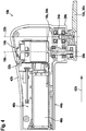
- FIG. 4 shows a side sectional view of an alternative machine tool 10b.
- the machine tool 10b is in the in FIG. 4 illustrated embodiment as a grinding machine, in particular as a delta sander formed. However, it is also conceivable for the machine tool 10b to have another configuration that appears appropriate to a person skilled in the art.
- the machine tool 10b is designed as an electrically driven machine tool 10b.
- the machine tool 10b is battery operated. Alternatively or In addition, it is conceivable that the machine tool 10b can be operated by cable.
- the machine tool 10b has a battery receptacle 40b, which is arranged in a housing 42b of the machine tool 10b.
- the housing 42b is designed in particular as a shell housing.
- the battery holder 40b is arranged at least substantially in a handle 44b of the machine tool 10b.
- the battery receptacle 40b is provided to receive a battery 46b for operation of the machine tool 10a.
- the machine tool 10b has an oscillating drivable tool holder 12b.
- the tool holder 12b is formed as a grinding plate 38b.
- the tool holder 12b is provided to receive an insert tool, in particular an abrasive sheet from an operator in a detachable manner.
- FIG. 5 shows a plan view of an underside of the tool holder 12b.
- the machine tool 10b has a drive unit 14b for driving the tool holder 12b.
- the drive unit 14b has an electric motor 52b, which is provided to convert electrical energy provided by the battery 46b into kinetic energy, in particular rotational energy.
- the drive unit 14b has a drive shaft 16b with a drive shaft 18b which cuts the tool holder 12b to drive at least the tool holder 12b.
- the drive shaft 16b is in particular at least partially formed by an armature shaft 54b of the electric motor 52b.
- the machine tool 10b comprises a bearing unit 20b for a movable mounting of the tool holder 12b about a bearing axis 22b of the bearing unit 20b, which cuts the tool holder 12b.
- the bearing unit 20b is provided in particular for movably supporting the tool holder 12b relative to the housing 42b of the machine tool 10b.
- the drive unit 14b is disposed inside the housing 42b behind the storage unit 20b.
- the drive shaft 18b is formed differently from the bearing shaft 22b.
- the bearing axis 22b and the drive axle 18b extend at least substantially spatially spaced from each other.
- the bearing axis 22b extends in particular exclusively along at least one component of the bearing unit 20b.
- the drive axle 18b extends in particular exclusively along at least one component of the drive unit 14b, in particular along the drive shaft 16b.
- the drive axle 18b extends at least substantially along the drive shaft 16b, in particular along the armature shaft 54b of the electric motor 52b.
- the drive axle 18b extends at least substantially parallel to the bearing axle 22b.
- the bearing axis 22b cuts the tool holder 12b offset to the drive axis 18b.
- the bearing axis 22b cuts the tool holder 12b at least substantially in the center.
- the bearing shaft 22b and the drive shaft 18a intersect the tool holder 12b in two spatially spaced intersection points 56b, 58b.
- the drive shaft 18b intersects the tool holder 12b at an intersection point 56b, which lies on a circle 60b enclosing the point of intersection 58b between the bearing axis 22b and the tool holder 12b.
- the drive shaft 18b intersects the tool holder 12a at an intersection 56b between the circle 60b enclosing the intersection 58a between the bearing shaft 22b and the tool holder 12b and a main extension direction 62b of the machine tool 10b.
- the drive shaft 18b cuts the tool holder 12a behind the bearing axis 22b.
- the bearing unit 20b has a bearing pin 24b extending along the bearing axis 22b, on which the tool holder 12b is rotatably mounted about the bearing axis 22b.
- the bearing pin 24b is at least substantially cylindrical.
- the bearing pin 24b is in particular at least frictionally formed with the housing 42b of the machine tool 10b.
- the bearing pin 24b may be formed integrally with the housing 42b of the machine tool 10b.
- the bearing axis 22b extends in particular at least substantially along a main extension direction of the journal 24b.
- the drive unit 14b has a rolling bearing 28b arranged eccentrically to the drive axle 18b on the drive shaft 16b.
- the rolling bearing 28b is designed in particular as a ball bearing.
- the rolling bearing 28b is provided to transmit a movement from the drive shaft 16b to the tool holder 12b.
- the tool holder 12b has two running surfaces 30b, 32b, which are provided to transfer a movement of the roller bearing 28b into a pendulum movement 36b of the tool holder 12b about the bearing axis 22b.
- the running surfaces 30b, 32b are in particular formed integrally with the tool holder 12b.
- the running surfaces 30b, 32b in particular run at least substantially parallel to one another.
- the rolling bearing 28b describes during a rotation of the drive shaft 16b an eccentric movement about the drive axis 18b.
- the eccentric to the drive shaft 18b disposed on the drive shaft 16b roller bearing 28b is provided during rotation of the drive shaft 16b to apply the treads 30b, 32b alternately with a force.
- the mutual loading of the running surfaces 30b, 32b is intended to put the tool holder 12b in a pendulum movement 36b about the bearing axis 22b.
Landscapes
- Engineering & Computer Science (AREA)
- Mechanical Engineering (AREA)
- Life Sciences & Earth Sciences (AREA)
- Wood Science & Technology (AREA)
- Forests & Forestry (AREA)
- Finish Polishing, Edge Sharpening, And Grinding By Specific Grinding Devices (AREA)
Applications Claiming Priority (1)
| Application Number | Priority Date | Filing Date | Title |
|---|---|---|---|
| DE102016223508.7A DE102016223508A1 (de) | 2016-11-28 | 2016-11-28 | Tragbare Werkzeugmaschine |
Publications (2)
| Publication Number | Publication Date |
|---|---|
| EP3330044A1 true EP3330044A1 (fr) | 2018-06-06 |
| EP3330044B1 EP3330044B1 (fr) | 2023-08-16 |
Family
ID=60182430
Family Applications (1)
| Application Number | Title | Priority Date | Filing Date |
|---|---|---|---|
| EP17198177.2A Active EP3330044B1 (fr) | 2016-11-28 | 2017-10-25 | Machine-outil portative |
Country Status (3)
| Country | Link |
|---|---|
| EP (1) | EP3330044B1 (fr) |
| CN (1) | CN108115621B (fr) |
| DE (1) | DE102016223508A1 (fr) |
Cited By (1)
| Publication number | Priority date | Publication date | Assignee | Title |
|---|---|---|---|---|
| WO2020136087A1 (fr) * | 2018-12-27 | 2020-07-02 | Robert Bosch Gmbh | Machine-outil portative |
Families Citing this family (1)
| Publication number | Priority date | Publication date | Assignee | Title |
|---|---|---|---|---|
| CN112454100B (zh) * | 2019-09-09 | 2024-10-11 | 宝时得机械(张家港)有限公司 | 电动工具 |
Citations (2)
| Publication number | Priority date | Publication date | Assignee | Title |
|---|---|---|---|---|
| EP2377647A1 (fr) * | 2010-04-16 | 2011-10-19 | C. & E. Fein GmbH | Outil manuel |
| JP5363870B2 (ja) * | 2009-05-14 | 2013-12-11 | 日東工器株式会社 | 偏芯回転運動を伴う研磨装置 |
Family Cites Families (8)
| Publication number | Priority date | Publication date | Assignee | Title |
|---|---|---|---|---|
| JPH0634929Y2 (ja) * | 1988-09-01 | 1994-09-14 | ヤスハラ株式会社 | 研磨装置 |
| DE4233728A1 (de) * | 1992-10-07 | 1994-04-14 | Bosch Gmbh Robert | Exzentertellerschleifer |
| DE19546310A1 (de) * | 1995-12-12 | 1997-06-19 | Troeger Johannes Dr Ing Habil | Vibrationsgeminderter Linearschwingschleifer |
| DE19826340A1 (de) * | 1998-06-12 | 1999-12-16 | Bosch Gmbh Robert | Schwingschleifer |
| DE102007018465A1 (de) * | 2007-04-19 | 2008-10-23 | Robert Bosch Gmbh | Motorisch angetriebene Werkzeugmaschine |
| DE102007018464A1 (de) * | 2007-04-19 | 2008-10-23 | Robert Bosch Gmbh | Motorisch angetriebene Werkzeugmaschine |
| WO2014023229A1 (fr) * | 2012-08-07 | 2014-02-13 | 苏州宝时得电动工具有限公司 | Outil de meulage électrique |
| DE102013100085A1 (de) * | 2013-01-07 | 2014-07-10 | C. & E. Fein Gmbh | Oszillierend angetriebene Werkzeugmaschine |
-
2016
- 2016-11-28 DE DE102016223508.7A patent/DE102016223508A1/de active Pending
-
2017
- 2017-10-25 EP EP17198177.2A patent/EP3330044B1/fr active Active
- 2017-11-28 CN CN201711213239.7A patent/CN108115621B/zh active Active
Patent Citations (2)
| Publication number | Priority date | Publication date | Assignee | Title |
|---|---|---|---|---|
| JP5363870B2 (ja) * | 2009-05-14 | 2013-12-11 | 日東工器株式会社 | 偏芯回転運動を伴う研磨装置 |
| EP2377647A1 (fr) * | 2010-04-16 | 2011-10-19 | C. & E. Fein GmbH | Outil manuel |
Non-Patent Citations (2)
| Title |
|---|
| ANONYMOUS: "SKIL 7.2V Detail Sander (00024250001), Part #: 2425_Type_1", TOOLPARTS, 1 July 1996 (1996-07-01), pages 1 - 3, XP093043998 |
| ANONYMOUS: "Skil", WIKIPEDIA, 30 March 2021 (2021-03-30), pages 1 - 4, XP093043978 |
Cited By (3)
| Publication number | Priority date | Publication date | Assignee | Title |
|---|---|---|---|---|
| WO2020136087A1 (fr) * | 2018-12-27 | 2020-07-02 | Robert Bosch Gmbh | Machine-outil portative |
| WO2020136086A1 (fr) * | 2018-12-27 | 2020-07-02 | Robert Bosch Gmbh | Machine-outil portative |
| US12122011B2 (en) | 2018-12-27 | 2024-10-22 | Robert Bosch Gmbh | Hand-held power tool |
Also Published As
| Publication number | Publication date |
|---|---|
| DE102016223508A1 (de) | 2018-05-30 |
| CN108115621B (zh) | 2022-09-20 |
| CN108115621A (zh) | 2018-06-05 |
| EP3330044B1 (fr) | 2023-08-16 |
Similar Documents
| Publication | Publication Date | Title |
|---|---|---|
| EP2139647B1 (fr) | Machine-outil entraînée par un moteur | |
| DE102005007843A1 (de) | Bandsäge | |
| EP2242613B1 (fr) | Machine-outil entraînée par un moteur | |
| EP2139654A1 (fr) | Machine-outil entraînée par un moteur | |
| EP2629933A2 (fr) | Outil de travail notamment outil électrique | |
| WO2015015015A1 (fr) | Arrangement comprenant une machine-outil à guidage manuel et un disque de dégrossissage | |
| DE102004058847A1 (de) | Schneidkopf für eine elektrische Haarschneidemaschine | |
| WO2016096244A1 (fr) | Système de machine-outil | |
| WO2012013389A1 (fr) | Outil amovible | |
| EP3330044B1 (fr) | Machine-outil portative | |
| EP2669044B1 (fr) | Système comprenant une machine-outil manuelle et un outil à plaque | |
| WO2012022508A1 (fr) | Machine-outil | |
| EP2377647B1 (fr) | Outil manuel | |
| DE102011005008A1 (de) | Werkzeugmaschinentrennvorrichtung | |
| DE2818667A1 (de) | Werkzeugmaschine zum raeumlichen polieren mit magnetschleifpulver im magnetfeld von werkstuecken, die die form eines rotationskoerpers besitzen | |
| EP3164252A1 (fr) | Dispositif d'entraînement en oscillation | |
| EP0875338B1 (fr) | Déchiqueteuse à lames-couronne | |
| DE102014218122A1 (de) | Batteriebetriebene Handwerkzeugmaschine mit mindestens einem Motorgehäuseteil | |
| EP3723940A1 (fr) | Machine-outil portative | |
| DE102012215450A1 (de) | Tragbare Werkzeugmaschine | |
| DE3535909A1 (de) | Haecksler oder dgl. zerkleinerungsmaschine | |
| DE202007006757U1 (de) | Schleifaggregat für eine Durchlaufschleifmaschine | |
| EP0730931A1 (fr) | Outil mécanisé pour meuler, râper, limer ou polir | |
| DE3621240A1 (de) | Handwerkzeugmaschine | |
| DE3539666C1 (de) | Motorisch angetriebene,handgefuehrte Maschine zum Entgraten,insbesondere von gelochten oder gestanzten Blechen |
Legal Events
| Date | Code | Title | Description |
|---|---|---|---|
| PUAI | Public reference made under article 153(3) epc to a published international application that has entered the european phase |
Free format text: ORIGINAL CODE: 0009012 |
|
| STAA | Information on the status of an ep patent application or granted ep patent |
Free format text: STATUS: THE APPLICATION HAS BEEN PUBLISHED |
|
| AK | Designated contracting states |
Kind code of ref document: A1 Designated state(s): AL AT BE BG CH CY CZ DE DK EE ES FI FR GB GR HR HU IE IS IT LI LT LU LV MC MK MT NL NO PL PT RO RS SE SI SK SM TR |
|
| AX | Request for extension of the european patent |
Extension state: BA ME |
|
| STAA | Information on the status of an ep patent application or granted ep patent |
Free format text: STATUS: REQUEST FOR EXAMINATION WAS MADE |
|
| 17P | Request for examination filed |
Effective date: 20181206 |
|
| RBV | Designated contracting states (corrected) |
Designated state(s): AL AT BE BG CH CY CZ DE DK EE ES FI FR GB GR HR HU IE IS IT LI LT LU LV MC MK MT NL NO PL PT RO RS SE SI SK SM TR |
|
| STAA | Information on the status of an ep patent application or granted ep patent |
Free format text: STATUS: EXAMINATION IS IN PROGRESS |
|
| 17Q | First examination report despatched |
Effective date: 20190916 |
|
| RAP1 | Party data changed (applicant data changed or rights of an application transferred) |
Owner name: ROBERT BOSCH GMBH |
|
| TPAC | Observations filed by third parties |
Free format text: ORIGINAL CODE: EPIDOSNTIPA |
|
| RIC1 | Information provided on ipc code assigned before grant |
Ipc: B24B 47/12 20060101ALI20230208BHEP Ipc: B25F 5/00 20060101ALI20230208BHEP Ipc: B24B 23/04 20060101AFI20230208BHEP |
|
| GRAP | Despatch of communication of intention to grant a patent |
Free format text: ORIGINAL CODE: EPIDOSNIGR1 |
|
| STAA | Information on the status of an ep patent application or granted ep patent |
Free format text: STATUS: GRANT OF PATENT IS INTENDED |
|
| INTG | Intention to grant announced |
Effective date: 20230420 |
|
| P01 | Opt-out of the competence of the unified patent court (upc) registered |
Effective date: 20230509 |
|
| GRAS | Grant fee paid |
Free format text: ORIGINAL CODE: EPIDOSNIGR3 |
|
| GRAA | (expected) grant |
Free format text: ORIGINAL CODE: 0009210 |
|
| STAA | Information on the status of an ep patent application or granted ep patent |
Free format text: STATUS: THE PATENT HAS BEEN GRANTED |
|
| AK | Designated contracting states |
Kind code of ref document: B1 Designated state(s): AL AT BE BG CH CY CZ DE DK EE ES FI FR GB GR HR HU IE IS IT LI LT LU LV MC MK MT NL NO PL PT RO RS SE SI SK SM TR |
|
| REG | Reference to a national code |
Ref country code: GB Ref legal event code: FG4D Free format text: NOT ENGLISH |
|
| REG | Reference to a national code |
Ref country code: CH Ref legal event code: EP |
|
| REG | Reference to a national code |
Ref country code: DE Ref legal event code: R096 Ref document number: 502017015223 Country of ref document: DE |
|
| REG | Reference to a national code |
Ref country code: IE Ref legal event code: FG4D Free format text: LANGUAGE OF EP DOCUMENT: GERMAN |
|
| REG | Reference to a national code |
Ref country code: LT Ref legal event code: MG9D |
|
| REG | Reference to a national code |
Ref country code: NL Ref legal event code: MP Effective date: 20230816 |
|
| PG25 | Lapsed in a contracting state [announced via postgrant information from national office to epo] |
Ref country code: GR Free format text: LAPSE BECAUSE OF FAILURE TO SUBMIT A TRANSLATION OF THE DESCRIPTION OR TO PAY THE FEE WITHIN THE PRESCRIBED TIME-LIMIT Effective date: 20231117 |
|
| PG25 | Lapsed in a contracting state [announced via postgrant information from national office to epo] |
Ref country code: IS Free format text: LAPSE BECAUSE OF FAILURE TO SUBMIT A TRANSLATION OF THE DESCRIPTION OR TO PAY THE FEE WITHIN THE PRESCRIBED TIME-LIMIT Effective date: 20231216 |
|
| PG25 | Lapsed in a contracting state [announced via postgrant information from national office to epo] |
Ref country code: SE Free format text: LAPSE BECAUSE OF FAILURE TO SUBMIT A TRANSLATION OF THE DESCRIPTION OR TO PAY THE FEE WITHIN THE PRESCRIBED TIME-LIMIT Effective date: 20230816 Ref country code: RS Free format text: LAPSE BECAUSE OF FAILURE TO SUBMIT A TRANSLATION OF THE DESCRIPTION OR TO PAY THE FEE WITHIN THE PRESCRIBED TIME-LIMIT Effective date: 20230816 Ref country code: PT Free format text: LAPSE BECAUSE OF FAILURE TO SUBMIT A TRANSLATION OF THE DESCRIPTION OR TO PAY THE FEE WITHIN THE PRESCRIBED TIME-LIMIT Effective date: 20231218 Ref country code: NO Free format text: LAPSE BECAUSE OF FAILURE TO SUBMIT A TRANSLATION OF THE DESCRIPTION OR TO PAY THE FEE WITHIN THE PRESCRIBED TIME-LIMIT Effective date: 20231116 Ref country code: NL Free format text: LAPSE BECAUSE OF FAILURE TO SUBMIT A TRANSLATION OF THE DESCRIPTION OR TO PAY THE FEE WITHIN THE PRESCRIBED TIME-LIMIT Effective date: 20230816 Ref country code: LV Free format text: LAPSE BECAUSE OF FAILURE TO SUBMIT A TRANSLATION OF THE DESCRIPTION OR TO PAY THE FEE WITHIN THE PRESCRIBED TIME-LIMIT Effective date: 20230816 Ref country code: LT Free format text: LAPSE BECAUSE OF FAILURE TO SUBMIT A TRANSLATION OF THE DESCRIPTION OR TO PAY THE FEE WITHIN THE PRESCRIBED TIME-LIMIT Effective date: 20230816 Ref country code: IS Free format text: LAPSE BECAUSE OF FAILURE TO SUBMIT A TRANSLATION OF THE DESCRIPTION OR TO PAY THE FEE WITHIN THE PRESCRIBED TIME-LIMIT Effective date: 20231216 Ref country code: HR Free format text: LAPSE BECAUSE OF FAILURE TO SUBMIT A TRANSLATION OF THE DESCRIPTION OR TO PAY THE FEE WITHIN THE PRESCRIBED TIME-LIMIT Effective date: 20230816 Ref country code: GR Free format text: LAPSE BECAUSE OF FAILURE TO SUBMIT A TRANSLATION OF THE DESCRIPTION OR TO PAY THE FEE WITHIN THE PRESCRIBED TIME-LIMIT Effective date: 20231117 Ref country code: FI Free format text: LAPSE BECAUSE OF FAILURE TO SUBMIT A TRANSLATION OF THE DESCRIPTION OR TO PAY THE FEE WITHIN THE PRESCRIBED TIME-LIMIT Effective date: 20230816 |
|
| PG25 | Lapsed in a contracting state [announced via postgrant information from national office to epo] |
Ref country code: PL Free format text: LAPSE BECAUSE OF FAILURE TO SUBMIT A TRANSLATION OF THE DESCRIPTION OR TO PAY THE FEE WITHIN THE PRESCRIBED TIME-LIMIT Effective date: 20230816 |
|
| PG25 | Lapsed in a contracting state [announced via postgrant information from national office to epo] |
Ref country code: ES Free format text: LAPSE BECAUSE OF FAILURE TO SUBMIT A TRANSLATION OF THE DESCRIPTION OR TO PAY THE FEE WITHIN THE PRESCRIBED TIME-LIMIT Effective date: 20230816 |
|
| PG25 | Lapsed in a contracting state [announced via postgrant information from national office to epo] |
Ref country code: SM Free format text: LAPSE BECAUSE OF FAILURE TO SUBMIT A TRANSLATION OF THE DESCRIPTION OR TO PAY THE FEE WITHIN THE PRESCRIBED TIME-LIMIT Effective date: 20230816 Ref country code: RO Free format text: LAPSE BECAUSE OF FAILURE TO SUBMIT A TRANSLATION OF THE DESCRIPTION OR TO PAY THE FEE WITHIN THE PRESCRIBED TIME-LIMIT Effective date: 20230816 Ref country code: ES Free format text: LAPSE BECAUSE OF FAILURE TO SUBMIT A TRANSLATION OF THE DESCRIPTION OR TO PAY THE FEE WITHIN THE PRESCRIBED TIME-LIMIT Effective date: 20230816 Ref country code: EE Free format text: LAPSE BECAUSE OF FAILURE TO SUBMIT A TRANSLATION OF THE DESCRIPTION OR TO PAY THE FEE WITHIN THE PRESCRIBED TIME-LIMIT Effective date: 20230816 Ref country code: DK Free format text: LAPSE BECAUSE OF FAILURE TO SUBMIT A TRANSLATION OF THE DESCRIPTION OR TO PAY THE FEE WITHIN THE PRESCRIBED TIME-LIMIT Effective date: 20230816 Ref country code: CZ Free format text: LAPSE BECAUSE OF FAILURE TO SUBMIT A TRANSLATION OF THE DESCRIPTION OR TO PAY THE FEE WITHIN THE PRESCRIBED TIME-LIMIT Effective date: 20230816 Ref country code: SK Free format text: LAPSE BECAUSE OF FAILURE TO SUBMIT A TRANSLATION OF THE DESCRIPTION OR TO PAY THE FEE WITHIN THE PRESCRIBED TIME-LIMIT Effective date: 20230816 |
|
| REG | Reference to a national code |
Ref country code: DE Ref legal event code: R097 Ref document number: 502017015223 Country of ref document: DE |
|
| PG25 | Lapsed in a contracting state [announced via postgrant information from national office to epo] |
Ref country code: MC Free format text: LAPSE BECAUSE OF FAILURE TO SUBMIT A TRANSLATION OF THE DESCRIPTION OR TO PAY THE FEE WITHIN THE PRESCRIBED TIME-LIMIT Effective date: 20230816 |
|
| REG | Reference to a national code |
Ref country code: CH Ref legal event code: PL |
|
| REG | Reference to a national code |
Ref country code: BE Ref legal event code: MM Effective date: 20231031 |
|
| PG25 | Lapsed in a contracting state [announced via postgrant information from national office to epo] |
Ref country code: LU Free format text: LAPSE BECAUSE OF NON-PAYMENT OF DUE FEES Effective date: 20231025 |
|
| PLBE | No opposition filed within time limit |
Free format text: ORIGINAL CODE: 0009261 |
|
| STAA | Information on the status of an ep patent application or granted ep patent |
Free format text: STATUS: NO OPPOSITION FILED WITHIN TIME LIMIT |
|
| PG25 | Lapsed in a contracting state [announced via postgrant information from national office to epo] |
Ref country code: LU Free format text: LAPSE BECAUSE OF NON-PAYMENT OF DUE FEES Effective date: 20231025 |
|
| PG25 | Lapsed in a contracting state [announced via postgrant information from national office to epo] |
Ref country code: CH Free format text: LAPSE BECAUSE OF NON-PAYMENT OF DUE FEES Effective date: 20231031 |
|
| 26N | No opposition filed |
Effective date: 20240517 |
|
| PG25 | Lapsed in a contracting state [announced via postgrant information from national office to epo] |
Ref country code: IT Free format text: LAPSE BECAUSE OF FAILURE TO SUBMIT A TRANSLATION OF THE DESCRIPTION OR TO PAY THE FEE WITHIN THE PRESCRIBED TIME-LIMIT Effective date: 20230816 Ref country code: CH Free format text: LAPSE BECAUSE OF NON-PAYMENT OF DUE FEES Effective date: 20231031 Ref country code: SI Free format text: LAPSE BECAUSE OF FAILURE TO SUBMIT A TRANSLATION OF THE DESCRIPTION OR TO PAY THE FEE WITHIN THE PRESCRIBED TIME-LIMIT Effective date: 20230816 |
|
| PG25 | Lapsed in a contracting state [announced via postgrant information from national office to epo] |
Ref country code: BE Free format text: LAPSE BECAUSE OF NON-PAYMENT OF DUE FEES Effective date: 20231031 |
|
| PG25 | Lapsed in a contracting state [announced via postgrant information from national office to epo] |
Ref country code: IE Free format text: LAPSE BECAUSE OF NON-PAYMENT OF DUE FEES Effective date: 20231025 |
|
| PG25 | Lapsed in a contracting state [announced via postgrant information from national office to epo] |
Ref country code: IE Free format text: LAPSE BECAUSE OF NON-PAYMENT OF DUE FEES Effective date: 20231025 |
|
| PG25 | Lapsed in a contracting state [announced via postgrant information from national office to epo] |
Ref country code: BG Free format text: LAPSE BECAUSE OF FAILURE TO SUBMIT A TRANSLATION OF THE DESCRIPTION OR TO PAY THE FEE WITHIN THE PRESCRIBED TIME-LIMIT Effective date: 20230816 |
|
| PG25 | Lapsed in a contracting state [announced via postgrant information from national office to epo] |
Ref country code: BG Free format text: LAPSE BECAUSE OF FAILURE TO SUBMIT A TRANSLATION OF THE DESCRIPTION OR TO PAY THE FEE WITHIN THE PRESCRIBED TIME-LIMIT Effective date: 20230816 |
|
| REG | Reference to a national code |
Ref country code: AT Ref legal event code: MM01 Ref document number: 1599572 Country of ref document: AT Kind code of ref document: T Effective date: 20231025 |
|
| PG25 | Lapsed in a contracting state [announced via postgrant information from national office to epo] |
Ref country code: AT Free format text: LAPSE BECAUSE OF NON-PAYMENT OF DUE FEES Effective date: 20231025 |
|
| PG25 | Lapsed in a contracting state [announced via postgrant information from national office to epo] |
Ref country code: AT Free format text: LAPSE BECAUSE OF NON-PAYMENT OF DUE FEES Effective date: 20231025 |
|
| PG25 | Lapsed in a contracting state [announced via postgrant information from national office to epo] |
Ref country code: CY Free format text: LAPSE BECAUSE OF FAILURE TO SUBMIT A TRANSLATION OF THE DESCRIPTION OR TO PAY THE FEE WITHIN THE PRESCRIBED TIME-LIMIT; INVALID AB INITIO Effective date: 20171025 |
|
| PG25 | Lapsed in a contracting state [announced via postgrant information from national office to epo] |
Ref country code: HU Free format text: LAPSE BECAUSE OF FAILURE TO SUBMIT A TRANSLATION OF THE DESCRIPTION OR TO PAY THE FEE WITHIN THE PRESCRIBED TIME-LIMIT; INVALID AB INITIO Effective date: 20171025 |
|
| PG25 | Lapsed in a contracting state [announced via postgrant information from national office to epo] |
Ref country code: TR Free format text: LAPSE BECAUSE OF FAILURE TO SUBMIT A TRANSLATION OF THE DESCRIPTION OR TO PAY THE FEE WITHIN THE PRESCRIBED TIME-LIMIT Effective date: 20230816 |
|
| PGFP | Annual fee paid to national office [announced via postgrant information from national office to epo] |
Ref country code: DE Payment date: 20251209 Year of fee payment: 9 |
|
| PGFP | Annual fee paid to national office [announced via postgrant information from national office to epo] |
Ref country code: GB Payment date: 20251024 Year of fee payment: 9 |
|
| PGFP | Annual fee paid to national office [announced via postgrant information from national office to epo] |
Ref country code: FR Payment date: 20251024 Year of fee payment: 9 |