EP3330465A1 - Dispositif à charnière limitant l'ouverture - Google Patents
Dispositif à charnière limitant l'ouverture Download PDFInfo
- Publication number
- EP3330465A1 EP3330465A1 EP17161046.2A EP17161046A EP3330465A1 EP 3330465 A1 EP3330465 A1 EP 3330465A1 EP 17161046 A EP17161046 A EP 17161046A EP 3330465 A1 EP3330465 A1 EP 3330465A1
- Authority
- EP
- European Patent Office
- Prior art keywords
- hinge
- hinge body
- rotation
- opening
- door
- Prior art date
- Legal status (The legal status is an assumption and is not a legal conclusion. Google has not performed a legal analysis and makes no representation as to the accuracy of the status listed.)
- Granted
Links
- 230000000903 blocking effect Effects 0.000 claims abstract description 88
- 230000003993 interaction Effects 0.000 claims abstract description 16
- 238000013016 damping Methods 0.000 claims description 34
- 230000009467 reduction Effects 0.000 claims description 5
- 230000002829 reductive effect Effects 0.000 claims description 5
- 230000003116 impacting effect Effects 0.000 claims 1
- 230000006378 damage Effects 0.000 description 7
- 229910052751 metal Inorganic materials 0.000 description 7
- 239000002184 metal Substances 0.000 description 7
- 239000004033 plastic Substances 0.000 description 7
- 229920003023 plastic Polymers 0.000 description 7
- 238000004519 manufacturing process Methods 0.000 description 6
- 239000000463 material Substances 0.000 description 6
- 239000011521 glass Substances 0.000 description 4
- 230000000670 limiting effect Effects 0.000 description 4
- 125000006850 spacer group Chemical group 0.000 description 4
- 230000008901 benefit Effects 0.000 description 3
- 239000013013 elastic material Substances 0.000 description 3
- 230000008859 change Effects 0.000 description 2
- 230000003247 decreasing effect Effects 0.000 description 2
- 238000011161 development Methods 0.000 description 2
- 230000018109 developmental process Effects 0.000 description 2
- 230000000694 effects Effects 0.000 description 2
- 238000012423 maintenance Methods 0.000 description 2
- 230000001404 mediated effect Effects 0.000 description 2
- 239000000203 mixture Substances 0.000 description 2
- 229910001369 Brass Inorganic materials 0.000 description 1
- RYGMFSIKBFXOCR-UHFFFAOYSA-N Copper Chemical compound [Cu] RYGMFSIKBFXOCR-UHFFFAOYSA-N 0.000 description 1
- 229910000831 Steel Inorganic materials 0.000 description 1
- 230000006978 adaptation Effects 0.000 description 1
- 238000004026 adhesive bonding Methods 0.000 description 1
- 229910052782 aluminium Inorganic materials 0.000 description 1
- XAGFODPZIPBFFR-UHFFFAOYSA-N aluminium Chemical compound [Al] XAGFODPZIPBFFR-UHFFFAOYSA-N 0.000 description 1
- 239000010951 brass Substances 0.000 description 1
- 238000000576 coating method Methods 0.000 description 1
- 239000002131 composite material Substances 0.000 description 1
- 150000001875 compounds Chemical class 0.000 description 1
- 238000010276 construction Methods 0.000 description 1
- 229910052802 copper Inorganic materials 0.000 description 1
- 239000010949 copper Substances 0.000 description 1
- 230000007423 decrease Effects 0.000 description 1
- 230000001419 dependent effect Effects 0.000 description 1
- 238000006073 displacement reaction Methods 0.000 description 1
- 230000005484 gravity Effects 0.000 description 1
- 230000006872 improvement Effects 0.000 description 1
- 230000007246 mechanism Effects 0.000 description 1
- 150000002739 metals Chemical class 0.000 description 1
- 238000003825 pressing Methods 0.000 description 1
- 230000000284 resting effect Effects 0.000 description 1
- 230000002441 reversible effect Effects 0.000 description 1
- 230000006641 stabilisation Effects 0.000 description 1
- 238000011105 stabilization Methods 0.000 description 1
- 239000010959 steel Substances 0.000 description 1
- 238000003466 welding Methods 0.000 description 1
Images

Classifications
-
- E—FIXED CONSTRUCTIONS
- E05—LOCKS; KEYS; WINDOW OR DOOR FITTINGS; SAFES
- E05D—HINGES OR SUSPENSION DEVICES FOR DOORS, WINDOWS OR WINGS
- E05D11/00—Additional features or accessories of hinges
- E05D11/06—Devices for limiting the opening movement of hinges
-
- E—FIXED CONSTRUCTIONS
- E05—LOCKS; KEYS; WINDOW OR DOOR FITTINGS; SAFES
- E05D—HINGES OR SUSPENSION DEVICES FOR DOORS, WINDOWS OR WINGS
- E05D11/00—Additional features or accessories of hinges
- E05D11/08—Friction devices between relatively-movable hinge parts
- E05D11/087—Friction devices between relatively-movable hinge parts with substantially axial friction, e.g. friction disks
-
- E—FIXED CONSTRUCTIONS
- E05—LOCKS; KEYS; WINDOW OR DOOR FITTINGS; SAFES
- E05D—HINGES OR SUSPENSION DEVICES FOR DOORS, WINDOWS OR WINGS
- E05D5/00—Construction of single parts, e.g. the parts for attachment
- E05D5/02—Parts for attachment, e.g. flaps
- E05D5/0246—Parts for attachment, e.g. flaps for attachment to glass panels
-
- E—FIXED CONSTRUCTIONS
- E05—LOCKS; KEYS; WINDOW OR DOOR FITTINGS; SAFES
- E05Y—INDEXING SCHEME ASSOCIATED WITH SUBCLASSES E05D AND E05F, RELATING TO CONSTRUCTION ELEMENTS, ELECTRIC CONTROL, POWER SUPPLY, POWER SIGNAL OR TRANSMISSION, USER INTERFACES, MOUNTING OR COUPLING, DETAILS, ACCESSORIES, AUXILIARY OPERATIONS NOT OTHERWISE PROVIDED FOR, APPLICATION THEREOF
- E05Y2600/00—Mounting or coupling arrangements for elements provided for in this subclass
- E05Y2600/50—Mounting methods; Positioning
- E05Y2600/52—Toolless
- E05Y2600/526—Gluing or cementing
-
- E—FIXED CONSTRUCTIONS
- E05—LOCKS; KEYS; WINDOW OR DOOR FITTINGS; SAFES
- E05Y—INDEXING SCHEME ASSOCIATED WITH SUBCLASSES E05D AND E05F, RELATING TO CONSTRUCTION ELEMENTS, ELECTRIC CONTROL, POWER SUPPLY, POWER SIGNAL OR TRANSMISSION, USER INTERFACES, MOUNTING OR COUPLING, DETAILS, ACCESSORIES, AUXILIARY OPERATIONS NOT OTHERWISE PROVIDED FOR, APPLICATION THEREOF
- E05Y2900/00—Application of doors, windows, wings or fittings thereof
- E05Y2900/10—Application of doors, windows, wings or fittings thereof for buildings or parts thereof
- E05Y2900/13—Type of wing
- E05Y2900/132—Doors
-
- E—FIXED CONSTRUCTIONS
- E05—LOCKS; KEYS; WINDOW OR DOOR FITTINGS; SAFES
- E05Y—INDEXING SCHEME ASSOCIATED WITH SUBCLASSES E05D AND E05F, RELATING TO CONSTRUCTION ELEMENTS, ELECTRIC CONTROL, POWER SUPPLY, POWER SIGNAL OR TRANSMISSION, USER INTERFACES, MOUNTING OR COUPLING, DETAILS, ACCESSORIES, AUXILIARY OPERATIONS NOT OTHERWISE PROVIDED FOR, APPLICATION THEREOF
- E05Y2900/00—Application of doors, windows, wings or fittings thereof
- E05Y2900/20—Application of doors, windows, wings or fittings thereof for furniture, e.g. cabinets
- E05Y2900/202—Application of doors, windows, wings or fittings thereof for furniture, e.g. cabinets for display cabinets, e.g. for refrigerated cabinets
Definitions
- the present invention relates to an opening-limiting hinge device and doors having such opening-limiting hinge devices.
- An opening-limiting hinge device includes a first hinge body, a second hinge body rotatably connected to the first hinge body, and a blocking member disposed on the first hinge body or the second hinge body.
- the blocking member is adapted to limit an angular range of rotation about an axis of rotation between the first hinge body and the second hinge body to a predetermined value by interaction or interaction with the second hinge body and the first hinge body, respectively.
- the blocking element can either be releasably connected to the hinge body or be an integral part of the hinge body.
- a further advantage of the above-described opening-limiting hinge device is that the blocking element which generates the limitation of the angle of rotation is integrated as part of one of the hinge bodies in the hinge device. This eliminates further lying outside of the hinge device elements for limiting the opening angle of a door connected to the hinge device. The angle limitation can therefore be generated inexpensively and without much effort by providing hinges.
- the blocking element may extend from the first hinge body parallel to the axis of rotation in the direction of the second hinge body, and the blocking element may be adapted to limit the angular range by interaction with a stopper element of the second hinge body to the predetermined value.
- the arrangement of the blocking element parallel to the axis of rotation ensures that a rotation about the axis of rotation in its angular range can be limited.
- the interaction of the blocking element with a specially provided for this stopper element increases the reliability of the limitation of the opening angle, while the hinge device can be made compact.
- the stopper member may have two end portions and the interaction may include abutting the blocking member at the end portions.
- the limitation of the angular range then takes place in a particularly simple manner via a mechanical interaction of the hinge body present within the hinge device or the blocking and stopper elements present on / in the latter. This allows a simple and inexpensive production of the hinge device.
- the second hinge body may have an elongated recess with two ends, in which engages the blocking element and the blocking element may be guided during rotation between the first hinge body and the second hinge body in the recess.
- the hinge is given additional stability, because due to the guidance of the blocking element in serving as a guide rail recess together with the connecting Rotary axis creates a two-point connection between the hinge bodies. This ensures that associated with the hinge device doors or door leaves when you open the door maintain their direction of rotation vertical orientation, ie that they do not tip down or to the side.
- the end regions with which the blocking element interacts may in this case have the ends of the depression.
- the blocking element is thus guided in the recess and at least partially abuts the ends of the recess when the limit of the allowed angular range is reached. That is, the depression forms an arcuate groove into which the blocking element engages.
- the angular range of this circular arc groove, recess, recess, or groove then defines the angular range of rotation between the hinge bodies. This provides a simple and inexpensive way to restrict the angular range of rotation.
- the end portions may include projections on the second hinge body extending from the second hinge body toward the first hinge body.
- the interaction between blocking element and stopper element is thus mediated in a simple manner by a stop of the blocking element on projections of the second hinge body.
- These projections may be present in addition to the recess described above. They then improve the stability of the stop. But you can also be mounted without the recess or guide groove.
- the structure of the hinge device is particularly simple, because only the attachment of projections in the correct angular position must be taken to each other in order to limit the rotation of the hinge body to a specific area.
- the striking of the blocking element can be cushioned on at least one of the end regions by a damping element. This ensures that at a rapid rotation of the hinge body to each other no damage to the attached elements of the door arise because an abrupt braking of the rotational movement, as may occur in an undamped stop, is prevented by the damping element.
- the damping element can in this case be arranged detachably at the respective end region.
- the damping element can then be replaced if necessary, z. When it is worn out. This allows the hinge device with damping element to be kept in use for a long time since the damping elements are exchanged can be. This saves the user of the hinge device additional costs and effort by replacing the hinge device.
- the first hinge body and the second hinge body may be detachably connected via the rotation axis.
- the axis of rotation thus produces the only connection between the hinge bodies.
- the releasability allows to remove door leaves connected to the hinge device from the associated door body without having to release the hinge device from the door.
- lying between the hinge bodies or intermediary between these elements, such as the blocking element or the stopper element, with their components in disassembled hinge bodies easily accessible. This facilitates the maintenance of the hinge device and the associated door.
- the blocking member may be attached to the first hinge body when connected to the second hinge body. This makes it possible to remove the blocking element even with composite hinge device from the hinge device. This facilitates the manufacture and maintenance of the hinge device.
- the first hinge body and the second hinge body can be arranged one behind the other along the rotation axis. This allows the space-saving arrangement of the hinge device.
- the hinge device can be made of any suitable material and z. B. made of metal, sufficiently hard plastics or a mixture thereof.
- the damping elements may be made of a sufficiently elastic material, such as rubber.
- the blocking member may include a screw member extending from the first hinge body along the rotation axis and screwed into a thread formed along the rotation axis in the second hinge body.
- the screw element can be connected to the first hinge body such that the screw element is screwed into the thread during rotation of the first hinge body relative to the second hinge body in such a way that a distance between the first hinge body and the second hinge body is reduced in the direction of the axis of rotation , By reducing the distance creates a force that counteracts the rotation.
- the blocking element thus comprises alternatively or additionally a screwed into the second hinge body screw. Upon a corresponding rotation of the hinge body of the hinge device, the screw continues to screw into the second hinge body. This reduces the distance between the two hinge bodies, which can be exploited in various ways to generate forces that counteract the rotation.
- an alternative or supporting embodiment of the blocking element is given, which also allows to restrict the angular range of rotation between the hinge bodies of the hinge device to a certain range of values.
- friction means e.g. Washers, metal cylinders, plastic parts or the like, be arranged between the hinge bodies such that when reducing the distance of the second hinge body, the friction means presses on the first hinge body.
- the reduction in the distance due to a spring device arranged between the hinge bodies can generate a spring force which counteracts a further reduction in the distance and thus the rotation.
- a spring force which is greater, the closer the hinge body come. This spring force counteracts the further screwing of the screw into the thread of the second hinge body and thus the rotation.
- the forces arising during the rotation can be set such that the angular range of the rotation is restricted to a certain range.
- the screw member may be immovable during rotation relative to the first hinge body. This ensures that with a relative rotation of the two hinge bodies to each other, the same rotation is also performed between the screw element and the thread, so that the screw element, depending on the direction of rotation, in the thread on or out of it is unscrewed.
- the screw may be an integral part of the first hinge body or screwed into this.
- the screw may be a by means of a locking means, such as a set screw or the like, locked on the first hinge body screw which engages through an opening of the first hinge body into the thread of the second hinge body.
- All of the elements described above as being disposed on the first hinge body may be disposed in mechanical reversal on the second hinge body. Then, all of the elements described above as being disposed on the second hinge body are disposed on the first hinge body.
- the blocking element also from the second hinge body in the direction of the first hinge body. Then the stopper element and its components are components of the first hinge body.
- a door may include a door body, a door panel adapted to close the door body and having the opening-limiting hinge device as described above, wherein the first hinge body is connected to the door body, and the second hinge body is connected to the door panel. This makes it possible to use the hinge device for limiting the opening angle of a door leaf relative to the associated door body.
- the first hinge body can be adhesively bonded to the door body and / or the second hinge body can be adhesively bonded to the door leaf. This allows for the components of the door nondestructive and secure connection between the hinge device and the door.
- the door body and / or the door leaf may be formed of glass. Since the problems described above are particularly for glass doors, damage can be prevented by using the hinge device for these doors.
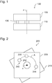
- FIG. 1 1 is a schematic cross-sectional view of an opening-limiting hinge device 100 according to one embodiment.
- the hinge device 100 has a first hinge body 110 and a second hinge body 120.
- the first hinge body 110 is connected to the second hinge body 120 such that the first hinge body 110 and the second hinge body 120 can be rotated about an axis of rotation z against each other.
- the connection between the first hinge body 110 and the second hinge body 120 may include the axis of rotation z, as in Fig. 1 shown, and z. B. along the axis of rotation z be solvable.
- connection z. B. by screwing the two hinge body 110, 120 may be formed, which allows enough clearance for a relative rotation.
- the axis of rotation is then approximately equal to the central axis of the screw used for screwing.
- the distance between the two hinge bodies 110, 120 can be ensured by spacers, for example, at least one washer.
- connection along the axis of rotation can also be effected by a plug connection between the first hinge body 110 and the second hinge body 120.
- One of the two hinge bodies 110, 120 is thereby attached to a pin or the like formed on the other hinge body 110, 120 and held by friction, mutual tension or gravity on the pin.
- connection can also be given in any other way, as long as the two hinge bodies 110, 120 rotate each other.
- connection may also be via a ball bearing which extends around the axis of rotation z, i. H. by a connection that does not include the rotation axis z.
- the compound may also have additional elements that allow the smoothest possible rotation.
- connection is designed such that the two hinge bodies 110, 120 lie one behind the other in the direction of the axis of rotation z and are substantially perpendicular to the axis of rotation z.
- the hinge device 100 has a blocking element 130, which is connected to one of the two hinge bodies 110, 120.
- This blocking element 130 interacts with the other hinge body 110, 120 and thereby prevents the two hinge bodies 110, 120 from being rotated as desired relative to one another.
- the interaction of the blocking element 130 with the hinge bodies 110, 120 can be of any type as long as a restriction of the angular range of rotation to the predetermined value is achieved.
- the interaction can z. B. be mechanical and z. B. realized by frictional forces or spring forces.
- the rotation may be limited by a mechanical abutment of parts of the hinge bodies 110, 120 to each other or by biasing a spring to a certain area.
- the blocking element 130 may extend, for example, from the first hinge body 110 parallel to the axis of rotation in the direction of the second hinge body 120 extend. On the second hinge body may then be arranged a stopper element with which the blocking element 130 interacts, for. B. by a mechanical stop.
- the interaction can also be electromagnetic and z. B. be mediated by attractive or repulsive forces between permanent or electromagnets.
- the blocking element 130 may be magnetized in such a way that, in a certain angular range of rotation, magnetic forces occur which prevent further rotation.
- the blocking element 130 is in this case connected to one of the two hinge bodies 110, 120, it is possible to restrict the angular range of the rotation without further components. This saves space. In addition, it is not necessary for a user of the hinge device 100 to additionally use an angle limiting device such as a door stopper.
- the predetermined value for the angular range is determined solely by the area of use of the hinge device 100, d. H. it depends on the desired opening angles for a door connected to the hinge device 100. If the opening angle in the closed state is designated 0 °, the predetermined value for the angular range can take any value, for. B. 60 °, 90 °, 120 °, 150 °, 180 °, 210 °, 240 ° and all intermediate angles in one or both directions, starting from the closed state.
- the hinge device 100 can in this case be made of any material or combination of materials that provides sufficient stability.
- all components may be made of one or more metals, such as metal.
- metals such as metal.
- steel aluminum, brass, copper or the like.
- Individual components, such as spacers, pins, screws or the hinge body 110, 120, or even the entire hinge device 100 may be made of sufficiently hard plastics.
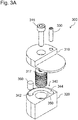
- the Fig. 2 shows a schematic plan view of a development of the hinge member 200 with the first hinge body 210 and the second hinge body 220.
- the restriction of the angular range to the predetermined value is achieved here by end portions 242, 244 of a stopper member 240 to which the blocking element 230 abuts.
- the blocking element 230 moves along the dashed line A until it abuts one of the end regions 242, 244.
- the position of the end regions 242, 244 thus determines the predetermined value of the available angular range for the rotation.
- one of the end portions 242, 244 may be arranged such that the blocking member 230 abuts there just when a door leaf held by the hinge device is closed, while the position of the other of the end regions 242, 244 indicates the maximum opening angle of the door leaf.
- the end regions 242, 244 can be set once during production.
- the end regions 242, 244 can also be variably attached to the second hinge body 220.
- the end portions can be formed as pins, screws or the like fixed in various prefabricated openings of the second hinge body 220, e.g. B. can be inserted or screwed.
- the path A and thus the available angular range can be increased or decreased.
- damping elements can be used as inserts, which brake a rotational movement in a damped manner and thus prevent a too rapid, possibly damaging deceleration by the stop of the blocking element 230 at the end regions 242, 244.
- the damping elements may be formed of any suitable material, such as rubber or a mechanical spring, and may be present on both end regions 242, 244 or only on one of the end regions 242, 244. In the event that the end portions 242, 244 are formed as projections, the damping elements may be formed as fixedly or detachably connected to the projections coatings.
- a recess serving as a guide rail can also serve as a stopper element 240 in combination with protrusions protruding from the second hinge body 220.
- the protrusions may be disposed on the second hinge body 220 such that the blocking member 230 abuts the protrusions prior to the end of the recess.
- the depression then serves not primarily to restrict the angular range of the rotation, but as an additional stabilization measure for the hinge device by providing a securely guided second connection between the first hinge body 210 and the second hinge body 220.
- the blocking element 230 may either be an integral part of the first hinge body 210 or may be detachably connected thereto.
- the blocking element 230 may, for. B. be designed as a pin or screw and be screwed or plugged into the first hinge body 210. In order to achieve greater variability, it may also be possible for the blocking element 230 to be fastened to different positions on the first hinge body 210.
- first hinge body 210 may also be attached from the side of the first hinge body 210 opposite the second hinge body 220, e.g. B. by a through opening for the first hinge body 210 is formed. Then, the blocking member 230 may be connected to the first hinge body 210 even if the hinge device 200 is otherwise completely assembled.
- end regions 242, 244 designed as pins, screws or the like can also be introduced and fastened through the second hinge body 220.
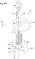
- the Fig. 3A . 3B and 3C show various schematic views of a hinge device 300.
- the Fig. 3A shows an exploded view, the Fig. 3B a cross section and the Fig. 3C a top view.
- the first hinge body 310 and the second hinge body 320 are connected to each other via a screw 315.
- a distance between the hinge bodies 310, 320 is achieved by a spacer set of washers 317 placed in a bore provided in the second hinge body 320.
- a height surplus of the washers 317 relative to the height of the bore then determines the distance between the hinge bodies 310, 320.
- the washers 317 can be replaced by any other spacer that allows a rotational movement between the hinge bodies 310, 320, z. B. by a plastic cylinder.
- the screw 315 is here pulled so tight that a rotation about the screw 315 can be performed. As described above, any other connection that allows such rotation is possible.
- the second hinge body 320 has a depression 350, which serves as a stopper element 340 with the end regions 342, 344.
- the ends of the elongated recess 350 thus serve as end regions 342, 344 of the stopper element.
- the blocking element 330 extending from the first hinge body 310 parallel to the axis of rotation in the direction of the second hinge body 320.
- This is designed as a pin-shaped screw which is introduced through an opening facing away from the second hinge body 320 opening in the first hinge body 310.
- the blocking element 330 can also be embodied in any other form, as long as it is ensured that it interacts with the second hinge body 320 in a suitable manner.
- the blocking element 330 may be formed as an integral part of the first hinge body or as a pin that is inserted into the first hinge body 310.
- the recess 350 serves not only as a stopper member 340 but also as a guide rail for the blocking member 330. This increases the stability of the hinge apparatus 300 ,
- a damping element 360 is arranged at one end of the recess. As shown, the damping element 360 can be released from the recess 350, so that a simple replacement of the damping element 360 can take place.
- the recess 350 at its end the shape of the damping element 360 adapted accordingly, for. B., to prevent displacement of the damping element 360 from the end of the recess 350 away.
- the damping element 360 may also be firmly connected to the second hinge body 320, for. B., the damping element 360 may be glued into the recess 350. An adaptation of the shape of the recess 350 to the damping element 360 is then not necessary.
- the damping element 360 is made of an elastic material which is suitable for damping the speed of the blocking element 350 generated relative to the end region 344 by the relative rotation of the hinge bodies 310, 320.
- the damping element 360 is made of rubber or a spring with the appropriate spring hardness.
- the blocking element 330 By virtue of the blocking element 330 engaging in the depression 350, it is ensured that rotation can take place only in the region which is defined by the travel path of the blocking element 330 in the depression 350. This effectively and simply restricts the angular range possible for a rotation to a predetermined value. This value just corresponds to the angle arc spanned by the depression 350.
- the opening angle can thus be defined during manufacture over the length of the recess 350. It is then possible in the following to reduce this maximum opening angle by inserting additional elements into the recess. Such additional elements may be damping elements 360, but also metal or plastic inserts that are not elastic.
- damping element 360 By attaching the damping element 360 to one end of the recess 350, it can be ensured that the rotation comes to a standstill in a damped manner. By attaching the damping element 360 at the end, which corresponds to the position of the blocking element 330 with the door open maximally, it can be ensured that the door is not braked so fast by the stop at the end portion 344 so fast that damage to the hinge device 300 , the door and / or the environment arise.
- the stopper member 340 may also be formed as a pair of protrusions serving as end portions 342, 344. Then, the blocking member 330 is only high enough to contact the second hinge body 320 only at the protrusions in the end portions 342, 344. The angular range is then limited instead of abutting the ends of the recess 350 by abutment with the projections in the end regions 342, 344.
- the recess 350 is then not necessary. Instead, in the end portions 342, 344, projections of the second hinge body 320, pins or screws, whose height is smaller than the distance between the hinge bodies 310, 320, but sufficiently large to be in contact with the blocking member 330 come.
- the end regions can in this case be coated with damping elements.
- an opening-limiting hinge device comprises a first hinge body, a second hinge body which is rotatably connected to the first hinge body about a rotation axis z and a blocking device or a blocking element.
- the blocking device or the blocking element has a screw element which extends from the first hinge body along the axis of rotation z and is screwed into a thread formed along the axis of rotation z in the second hinge body.
- the screw element is connected to the first hinge body such that the screw element is screwed into the thread during rotation of the first hinge body relative to the second hinge body or guided in the thread, that a distance between the first hinge body and the second hinge body in Direction of the rotation axis z reduced. By reducing the distance creates a force that counteracts the rotation.
- the hinge device can be described above with reference to FIGS Fig. 1 to 3C correspond described hinge devices.
- the blocking device or the blocking element of the hinge device may contain further blocking elements, as described above with reference to FIGS Fig. 1 to 3C have been described.
- the blocking device with the screw is also alone suitable to limit an angular range of rotation about the rotation axis z between the first hinge body and the second hinge body by interaction with the second hinge body, more precisely with the thread to a predetermined value.
- a screw and one of the blocking elements with respect to the Fig. 1 to 3 have been described, so support these blocking elements in the limitation of the angular range as a blocking device.
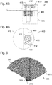
- the opening-limiting hinge device 400 of FIGS. 4A to 4C includes a first hinge body 410, a second hinge body 420 and a stopper member 440 having an elongated recess 450, a damping member 360 and end portions 442, 444 as described above with respect to FIGS Figs. 3A to 3C already described. These interact in the manner described above with a blocking element 431 extending from the first hinge body 410 extends parallel to the rotation axis z in the direction of the second hinge body 420.
- the blocking element 431 and the stopper element 440 do not necessarily have to be present in order to limit a limitation of the opening angle of a relative rotation between the first and second hinge bodies 410, 420.
- the hinge device 400 has a blocking device 430 which, in addition to the blocking element 431, comprises a further blocking element designed as a screw element 415.
- the screw element 415 extends along the rotation axis z in the direction of the second hinge body 420 and is screwed into a thread 421 which is formed along the rotation axis z in the second hinge body 420. If the two hinge bodies 410, 420 are rotated relative to each other, this will, depending on the direction of rotation, cause the screw element 415 to be screwed into the thread 421 or out of the thread 421. This results in a change in the distance between the two hinge bodies 410, 420 due to the change in the length of a protruding from the thread 421 part of the screw 415.
- the screw 415 can in this case, for example, as in the FIGS. 4A to 4C represented as a screw which is guided through an opening 416 of the first hinge element 410.
- the screw 415 can also be connected directly to the first hinge body 410, for example as an integral part of the first hinge body 410.
- the screw 415 can also take any other arbitrary shape, which allows it to be screwed into the thread 421, that upon appropriate rotation the hinge body 410, 420 to each other, the distance between the hinge bodies 410, 420 is reduced.
- washers 417 or the like may be interposed as friction means between the hinge bodies 410, 420 to achieve that, even if there is still a clearance between the first hinge body 410 and second hinge body 420, due to the friction between friction means 417 and hinge bodies 410, 420 a rotation comes to a halt and is thus limited in their available angular range. Due to the exact configuration of the friction means, for example the number or thickness of the washers 417, the permitted angular range can be adjusted.
- Washers 417 are shown as friction means disposed concentrically about the rotation axis z and the screw member 415, it is also possible to arrange differently shaped friction means, eg metal or plastic members elsewhere between the hinge bodies 410, 420, to increase the frictional force to achieve.
- a spring device such as a spring, an elastic material, or the like, may be interposed between the hinge bodies 410, 420.
- a spring device such as a spring, an elastic material, or the like, may be interposed between the hinge bodies 410, 420.
- the in Fig. 4A shown set washers 417 also be replaced by a spring.
- the spring device need not be disposed around the screw member 415, but may be mounted at any suitable location between the hinge bodies 415.
- the spring device Upon rotation of the hinge body 410, 420 to each other, due to which the distance between the hinge bodies 410, 420 decreases, the spring device is increasingly stretched, whereby an increasingly strong spring force builds up, even if the hinge body 410, 420 are not yet pressed together , If the spring force is so large that it compensates for the torque leading to the rotation or the force caused by this torque and the guidance of the screw 415 in the thread 421 parallel to the axis of rotation z, the rotation comes to a standstill. By selecting the spring hardness or the elasticity of the spring device, an angular range for the rotation can be restricted.
- a screw as in Fig. 4A is shown, with respect to both hinge bodies 410, 420 rotate.
- the rotation with respect to the first hinge body 410 is substantially less than the rotation with respect to the second hinge body 420, because due to the thread 421 of this rotation less friction is opposed.
- the rotation of the screw member 415 with respect to the first hinge body 410 is negligible and the rotation of the hinge bodies 410, 420 relative to each other results in the effects described above.
- a locking means 413 such as a screw, a bolt, a pin or the like, is used for locking the screw 415 via a bore 412.
- the locking can be effected by pressing the locking means 413 by screwing into the bore 412 to one side of the screw element 415 such that movement of the screw element 415 relative to the first hinge body 410 is prevented.
- the screw member may also be integrally connected to the first hinge body.
- the screw instead of a screw may also be an emphasis on the first hinge body, which has a pin or pin shape and into which a thread is cut.
- the screw element can also be used e.g. by welding or gluing subsequently be firmly connected to the first hinge body and therefore be immovable relative to the first hinge body.
- a screw member 415 which can be locked by locking means 413, offers the advantage that, when the lock is initially open, the screw element 415 can be screwed as far as desired into the thread 421 of the second hinge body 420, by the initial distance of the hinge bodies 410, 420 from the front to adjust the actual rotation that occurs when using the hinge device 400.
- the distance and thus also the force to be applied during rotation of the hinge bodies 410, 420 can be adjusted by first screwing the screw element 415 into the thread 421 to the desired length, and then by means of locking the screw element 415 with the locking means 413 a relative movement is blocked by screw 415 and first hinge body 410 to each other. Thereby, the angular range of rotation between the two hinge bodies 410, 420 can be effectively restricted.
- the hinge device 400 may be constructed differently for a desired damping on the one hand in a left-handed opening movement, so for example in a counter-clockwise opening door, and on the other hand in a clockwise opening movement, so for example in a counter-clockwise opening door.
- a desired damping on the one hand in a left-handed opening movement so for example in a counter-clockwise opening door
- a clockwise opening movement so for example in a counter-clockwise opening door.
- either the direction of rotation of the thread 421 and the associated screw 415 can be adjusted according to the desired direction of damping rotation, so either a right-hand thread or a left-hand thread can be provided.
- the screw element 415 in the first hinge device 410 and the thread 421 in the second hinge device 420 can be provided, or else the screw element 415 in the second hinge device 420 and the thread 421 in the first one Hinge device 410 may be provided, depending on the desired damping direction.
- a hinge device 400 of the same type can be easily installed rotated by 180 ° to a perpendicular to the rotation axis z to produce different damping directions.
- a hinge device 400 comprises a first hinge body 410 and a second hinge body 420, which is rotatably connected to the first hinge body 410 about a rotation axis z.
- a screw member 415 of the hinge device 400 extends from the first hinge body 410 along the rotation axis z into a thread 421 formed along the rotation axis z in the second hinge body 420 and is screwed therein.
- the screw member 415 is connected to the first hinge body 410 such that the screw member 415 is screwed into the thread 421 in rotation of the first hinge body 410 relative to the second hinge body 420 or guided in the thread 421 such that there is a space between them the first hinge body 410 and the second hinge body 420 is reduced in the direction of the rotation axis z.
- the hinge device 400 may thus be designed as a damping hinge device.
- the dimension of the hinge devices 100, 200, 300 or 400 along the rotation axis z may be in a range between 5 mm and 200 mm, or between 10 mm and 100 mm, or between 20 mm and 50 mm, however, the application of the principle according to the invention not limited in principle with respect to a dimension of the hinge device.
- the Fig. 5 shows a schematic representation of a door 500 which is held by means of one of the hinge device described above. Exemplary is the in the Figs. 3A to 3C shown hinge device 300 in the Fig. 5 shown.
- the first hinge body 310 is in this case connected to a door body 570, such as a door frame, a door sill or a cabinet body, while the second hinge body 320 is connected to a door leaf 580.
- the hinge body 310, 320 may be glued to the door body 570 and the door leaf 580, respectively.
- the first hinge body may have an L-shaped recess into which the door body 570 may be glued.
- the second hinge body may have a flat side onto which the door panel 580 may be glued.
- the first hinge body 310 rests on the bottom of the door body 570.
- the door body 570 may in this case be a door frame, the body of a cabinet or just a portion of the floor.
- the first hinge body 310 having the L-shaped recess may be bonded to the front edge of a cabinet body, as in FIG Fig. 5 shown. This allows the hinge device 300 to be connected to it without destroying the door body 570.
- the second hinge body 320 rests on the first hinge body 310.
- the door panel 580 By attaching the door panel 580 to the flat side of the second hinge body 320, the door panel 580 can pivot against the door body 570 and the first hinge member 310.
- the possible opening angle is limited in this case by the interaction of the blocking element 330 with the second hinge body 320. This prevents the door leaf 580 from opening too far and thereby damaging other furnishings or jamming and / or tensioning the door or the hinge device itself.
- a plurality of hinge devices are used to connect door leaf 580 and door body 570 to provide more stability to the door, e.g. B. each hinge device at opposite locations on opposite sides of a door panel.
- two hinge devices 300 are placed on the door body 570 and fastened so that their axes of rotation come to rest on each other.
- a hinge device 300 in the in Fig. 3B shown stuck to the upper front edge of a front open cabinet body, while a second hinge device 300 in the reverse position, as in Fig. 5 is glued to the lower front edge of the cabinet body.
- the hinge bodies 310, 320 of the hinge device 300 can in be formed of any shape, for. B. semicircular or cylindrical, as shown in the figures, but also purely cubic or in free form, which is not based on geometric body, as long as this allows the hinge body 310, 320 to the door body 570 and the door leaf 580 of a door 500 to attach.
- the door body 570 and / or the door leaf 580 are preferably made of glass, since glass doors are particularly susceptible to damage due to too fast and / or too wide opening.
- the hinge devices described above can be made of any suitable material and z. B. made of metal, sufficiently hard plastics or a mixture thereof.
- the blocking element can also be connected to the hinge body which holds the door leaf, d. H. with the second hinge body.
- the stopper element and its components may be connected to or formed in the hinge body, which is connected to the door body, d. H. with the first hinge body.
Landscapes
- Engineering & Computer Science (AREA)
- Mechanical Engineering (AREA)
- Hinges (AREA)
Applications Claiming Priority (1)
| Application Number | Priority Date | Filing Date | Title |
|---|---|---|---|
| DE202016106763.4U DE202016106763U1 (de) | 2016-12-05 | 2016-12-05 | Öffnungsbegrenzende Scharniervorrichtung |
Publications (2)
| Publication Number | Publication Date |
|---|---|
| EP3330465A1 true EP3330465A1 (fr) | 2018-06-06 |
| EP3330465B1 EP3330465B1 (fr) | 2019-05-08 |
Family
ID=57738735
Family Applications (1)
| Application Number | Title | Priority Date | Filing Date |
|---|---|---|---|
| EP17161046.2A Active EP3330465B1 (fr) | 2016-12-05 | 2017-03-15 | Dispositif à charnière limitant l'ouverture |
Country Status (2)
| Country | Link |
|---|---|
| EP (1) | EP3330465B1 (fr) |
| DE (1) | DE202016106763U1 (fr) |
Cited By (1)
| Publication number | Priority date | Publication date | Assignee | Title |
|---|---|---|---|---|
| CN113931545A (zh) * | 2021-09-03 | 2022-01-14 | 合肥华凌股份有限公司 | 限位装置、铰链组件和储物柜 |
Citations (5)
| Publication number | Priority date | Publication date | Assignee | Title |
|---|---|---|---|---|
| DE19833924A1 (de) * | 1998-07-28 | 2000-02-03 | Scharwaechter Ed Gmbh | Mit einer integrierten Türbremse ausgestattetes Türscharnier |
| DE10308136A1 (de) * | 2003-02-26 | 2004-09-30 | Audi Ag | Türscharnier mit integriertem Türfeststeller für Kraftfahrzeugtüren |
| WO2007128839A1 (fr) * | 2006-05-10 | 2007-11-15 | Deike, Ingrid | Charnière rotative |
| US20090172916A1 (en) * | 2008-01-04 | 2009-07-09 | Jr-Jiun Chern | Hinge Assembly |
| US20160208531A1 (en) * | 2015-01-19 | 2016-07-21 | Kohler Co. | Shower door assemblies |
-
2016
- 2016-12-05 DE DE202016106763.4U patent/DE202016106763U1/de not_active Expired - Lifetime
-
2017
- 2017-03-15 EP EP17161046.2A patent/EP3330465B1/fr active Active
Patent Citations (5)
| Publication number | Priority date | Publication date | Assignee | Title |
|---|---|---|---|---|
| DE19833924A1 (de) * | 1998-07-28 | 2000-02-03 | Scharwaechter Ed Gmbh | Mit einer integrierten Türbremse ausgestattetes Türscharnier |
| DE10308136A1 (de) * | 2003-02-26 | 2004-09-30 | Audi Ag | Türscharnier mit integriertem Türfeststeller für Kraftfahrzeugtüren |
| WO2007128839A1 (fr) * | 2006-05-10 | 2007-11-15 | Deike, Ingrid | Charnière rotative |
| US20090172916A1 (en) * | 2008-01-04 | 2009-07-09 | Jr-Jiun Chern | Hinge Assembly |
| US20160208531A1 (en) * | 2015-01-19 | 2016-07-21 | Kohler Co. | Shower door assemblies |
Cited By (2)
| Publication number | Priority date | Publication date | Assignee | Title |
|---|---|---|---|---|
| CN113931545A (zh) * | 2021-09-03 | 2022-01-14 | 合肥华凌股份有限公司 | 限位装置、铰链组件和储物柜 |
| CN113931545B (zh) * | 2021-09-03 | 2022-11-04 | 合肥华凌股份有限公司 | 限位装置、铰链组件和储物柜 |
Also Published As
| Publication number | Publication date |
|---|---|
| EP3330465B1 (fr) | 2019-05-08 |
| DE202016106763U1 (de) | 2016-12-20 |
Similar Documents
| Publication | Publication Date | Title |
|---|---|---|
| EP3612700B1 (fr) | Paroi de meuble avec un clapet et un corps de meuble et meuble avec une telle paroi de meuble | |
| EP2617336B1 (fr) | Séparation de douche | |
| EP2439363B1 (fr) | Barre anti-panique à compression | |
| EP1709270A1 (fr) | Fixation de pinces pour le montage de dispositifs de ferrures, tels que fermetures, elements de charniere, poignees dans des passages au travers d'une paroi mince | |
| EP1274908B1 (fr) | Verrou destine a etre monte dans une ouverture pratiquee dans une paroi mince | |
| EP1711672B1 (fr) | Charniere a monter dans une ouverture | |
| DE102019124722A1 (de) | Türfeststellermechanismus | |
| EP3277899A1 (fr) | Système de poignée de porte d'un véhicule automobile | |
| EP3175068B1 (fr) | Système de ferrure | |
| WO2021004700A1 (fr) | Charnière et système pour le raccordement amovible d'une porte à un cadre | |
| EP3330465B1 (fr) | Dispositif à charnière limitant l'ouverture | |
| EP1982032A1 (fr) | Fixation pour portes, fene | |
| DE10031403C2 (de) | Obentürschließer mit einer Gleitschienenanordnung | |
| DE29710853U1 (de) | Scharnier für Blechschranktüren | |
| DE102008036151A1 (de) | Scharnierband mit einer Unterkonstruktion zur Befestigung an einem Türblatt | |
| DE2210614C3 (de) | Weitwinkelscharnier | |
| EP1951977B1 (fr) | Bloc-porte mécanique pour portes, notamment pour portières de véhicule | |
| DE202015100200U1 (de) | Bandlappenanordnung eines Bandes | |
| EP1563152B1 (fr) | Charniere | |
| DE102014103558B3 (de) | Selbstschließendes Rollentürband | |
| DE102017126368A1 (de) | Möbelplatte mit einem Klappenbeschlag und Möbelkorpus sowie Möbel mit einer derartigen Möbelplatte | |
| EP2511463B1 (fr) | Fenêtre, porte ou analogue pourvue d'un dispositif d'amortissement | |
| DE10147477A1 (de) | Schließfolgeregler | |
| EP4375463B1 (fr) | Élément de ferrure | |
| EP2385209B1 (fr) | Dispositif de réglage de l'inclinaison d'un vantail |
Legal Events
| Date | Code | Title | Description |
|---|---|---|---|
| PUAI | Public reference made under article 153(3) epc to a published international application that has entered the european phase |
Free format text: ORIGINAL CODE: 0009012 |
|
| STAA | Information on the status of an ep patent application or granted ep patent |
Free format text: STATUS: THE APPLICATION HAS BEEN PUBLISHED |
|
| AK | Designated contracting states |
Kind code of ref document: A1 Designated state(s): AL AT BE BG CH CY CZ DE DK EE ES FI FR GB GR HR HU IE IS IT LI LT LU LV MC MK MT NL NO PL PT RO RS SE SI SK SM TR |
|
| AX | Request for extension of the european patent |
Extension state: BA ME |
|
| STAA | Information on the status of an ep patent application or granted ep patent |
Free format text: STATUS: REQUEST FOR EXAMINATION WAS MADE |
|
| 17P | Request for examination filed |
Effective date: 20180620 |
|
| RBV | Designated contracting states (corrected) |
Designated state(s): AL AT BE BG CH CY CZ DE DK EE ES FI FR GB GR HR HU IE IS IT LI LT LU LV MC MK MT NL NO PL PT RO RS SE SI SK SM TR |
|
| GRAP | Despatch of communication of intention to grant a patent |
Free format text: ORIGINAL CODE: EPIDOSNIGR1 |
|
| STAA | Information on the status of an ep patent application or granted ep patent |
Free format text: STATUS: GRANT OF PATENT IS INTENDED |
|
| INTG | Intention to grant announced |
Effective date: 20180925 |
|
| GRAS | Grant fee paid |
Free format text: ORIGINAL CODE: EPIDOSNIGR3 |
|
| GRAA | (expected) grant |
Free format text: ORIGINAL CODE: 0009210 |
|
| STAA | Information on the status of an ep patent application or granted ep patent |
Free format text: STATUS: THE PATENT HAS BEEN GRANTED |
|
| REG | Reference to a national code |
Ref country code: DE Ref legal event code: R082 Ref document number: 502017001255 Country of ref document: DE Representative=s name: MUELLER HOFFMANN & PARTNER PATENTANWAELTE MBB, DE Ref country code: DE Ref legal event code: R082 Ref document number: 502017001255 Country of ref document: DE |
|
| AK | Designated contracting states |
Kind code of ref document: B1 Designated state(s): AL AT BE BG CH CY CZ DE DK EE ES FI FR GB GR HR HU IE IS IT LI LT LU LV MC MK MT NL NO PL PT RO RS SE SI SK SM TR |
|
| REG | Reference to a national code |
Ref country code: GB Ref legal event code: FG4D Free format text: NOT ENGLISH |
|
| REG | Reference to a national code |
Ref country code: DE Ref legal event code: R082 Ref document number: 502017001255 Country of ref document: DE Representative=s name: MUELLER HOFFMANN & PARTNER PATENTANWAELTE MBB, DE |
|
| REG | Reference to a national code |
Ref country code: CH Ref legal event code: EP Ref country code: AT Ref legal event code: REF Ref document number: 1130376 Country of ref document: AT Kind code of ref document: T Effective date: 20190515 |
|
| REG | Reference to a national code |
Ref country code: DE Ref legal event code: R096 Ref document number: 502017001255 Country of ref document: DE Ref country code: IE Ref legal event code: FG4D Free format text: LANGUAGE OF EP DOCUMENT: GERMAN |
|
| REG | Reference to a national code |
Ref country code: NL Ref legal event code: MP Effective date: 20190508 |
|
| REG | Reference to a national code |
Ref country code: LT Ref legal event code: MG4D |
|
| PG25 | Lapsed in a contracting state [announced via postgrant information from national office to epo] |
Ref country code: ES Free format text: LAPSE BECAUSE OF FAILURE TO SUBMIT A TRANSLATION OF THE DESCRIPTION OR TO PAY THE FEE WITHIN THE PRESCRIBED TIME-LIMIT Effective date: 20190508 Ref country code: LT Free format text: LAPSE BECAUSE OF FAILURE TO SUBMIT A TRANSLATION OF THE DESCRIPTION OR TO PAY THE FEE WITHIN THE PRESCRIBED TIME-LIMIT Effective date: 20190508 Ref country code: NL Free format text: LAPSE BECAUSE OF FAILURE TO SUBMIT A TRANSLATION OF THE DESCRIPTION OR TO PAY THE FEE WITHIN THE PRESCRIBED TIME-LIMIT Effective date: 20190508 Ref country code: HR Free format text: LAPSE BECAUSE OF FAILURE TO SUBMIT A TRANSLATION OF THE DESCRIPTION OR TO PAY THE FEE WITHIN THE PRESCRIBED TIME-LIMIT Effective date: 20190508 Ref country code: AL Free format text: LAPSE BECAUSE OF FAILURE TO SUBMIT A TRANSLATION OF THE DESCRIPTION OR TO PAY THE FEE WITHIN THE PRESCRIBED TIME-LIMIT Effective date: 20190508 Ref country code: FI Free format text: LAPSE BECAUSE OF FAILURE TO SUBMIT A TRANSLATION OF THE DESCRIPTION OR TO PAY THE FEE WITHIN THE PRESCRIBED TIME-LIMIT Effective date: 20190508 Ref country code: NO Free format text: LAPSE BECAUSE OF FAILURE TO SUBMIT A TRANSLATION OF THE DESCRIPTION OR TO PAY THE FEE WITHIN THE PRESCRIBED TIME-LIMIT Effective date: 20190808 Ref country code: PT Free format text: LAPSE BECAUSE OF FAILURE TO SUBMIT A TRANSLATION OF THE DESCRIPTION OR TO PAY THE FEE WITHIN THE PRESCRIBED TIME-LIMIT Effective date: 20190908 Ref country code: SE Free format text: LAPSE BECAUSE OF FAILURE TO SUBMIT A TRANSLATION OF THE DESCRIPTION OR TO PAY THE FEE WITHIN THE PRESCRIBED TIME-LIMIT Effective date: 20190508 |
|
| PG25 | Lapsed in a contracting state [announced via postgrant information from national office to epo] |
Ref country code: LV Free format text: LAPSE BECAUSE OF FAILURE TO SUBMIT A TRANSLATION OF THE DESCRIPTION OR TO PAY THE FEE WITHIN THE PRESCRIBED TIME-LIMIT Effective date: 20190508 Ref country code: GR Free format text: LAPSE BECAUSE OF FAILURE TO SUBMIT A TRANSLATION OF THE DESCRIPTION OR TO PAY THE FEE WITHIN THE PRESCRIBED TIME-LIMIT Effective date: 20190809 Ref country code: RS Free format text: LAPSE BECAUSE OF FAILURE TO SUBMIT A TRANSLATION OF THE DESCRIPTION OR TO PAY THE FEE WITHIN THE PRESCRIBED TIME-LIMIT Effective date: 20190508 Ref country code: BG Free format text: LAPSE BECAUSE OF FAILURE TO SUBMIT A TRANSLATION OF THE DESCRIPTION OR TO PAY THE FEE WITHIN THE PRESCRIBED TIME-LIMIT Effective date: 20190808 |
|
| PG25 | Lapsed in a contracting state [announced via postgrant information from national office to epo] |
Ref country code: CZ Free format text: LAPSE BECAUSE OF FAILURE TO SUBMIT A TRANSLATION OF THE DESCRIPTION OR TO PAY THE FEE WITHIN THE PRESCRIBED TIME-LIMIT Effective date: 20190508 Ref country code: RO Free format text: LAPSE BECAUSE OF FAILURE TO SUBMIT A TRANSLATION OF THE DESCRIPTION OR TO PAY THE FEE WITHIN THE PRESCRIBED TIME-LIMIT Effective date: 20190508 Ref country code: SK Free format text: LAPSE BECAUSE OF FAILURE TO SUBMIT A TRANSLATION OF THE DESCRIPTION OR TO PAY THE FEE WITHIN THE PRESCRIBED TIME-LIMIT Effective date: 20190508 Ref country code: EE Free format text: LAPSE BECAUSE OF FAILURE TO SUBMIT A TRANSLATION OF THE DESCRIPTION OR TO PAY THE FEE WITHIN THE PRESCRIBED TIME-LIMIT Effective date: 20190508 Ref country code: DK Free format text: LAPSE BECAUSE OF FAILURE TO SUBMIT A TRANSLATION OF THE DESCRIPTION OR TO PAY THE FEE WITHIN THE PRESCRIBED TIME-LIMIT Effective date: 20190508 |
|
| REG | Reference to a national code |
Ref country code: DE Ref legal event code: R097 Ref document number: 502017001255 Country of ref document: DE |
|
| PG25 | Lapsed in a contracting state [announced via postgrant information from national office to epo] |
Ref country code: IT Free format text: LAPSE BECAUSE OF FAILURE TO SUBMIT A TRANSLATION OF THE DESCRIPTION OR TO PAY THE FEE WITHIN THE PRESCRIBED TIME-LIMIT Effective date: 20190508 Ref country code: SM Free format text: LAPSE BECAUSE OF FAILURE TO SUBMIT A TRANSLATION OF THE DESCRIPTION OR TO PAY THE FEE WITHIN THE PRESCRIBED TIME-LIMIT Effective date: 20190508 |
|
| PLBE | No opposition filed within time limit |
Free format text: ORIGINAL CODE: 0009261 |
|
| STAA | Information on the status of an ep patent application or granted ep patent |
Free format text: STATUS: NO OPPOSITION FILED WITHIN TIME LIMIT |
|
| PG25 | Lapsed in a contracting state [announced via postgrant information from national office to epo] |
Ref country code: TR Free format text: LAPSE BECAUSE OF FAILURE TO SUBMIT A TRANSLATION OF THE DESCRIPTION OR TO PAY THE FEE WITHIN THE PRESCRIBED TIME-LIMIT Effective date: 20190508 |
|
| 26N | No opposition filed |
Effective date: 20200211 |
|
| PG25 | Lapsed in a contracting state [announced via postgrant information from national office to epo] |
Ref country code: PL Free format text: LAPSE BECAUSE OF FAILURE TO SUBMIT A TRANSLATION OF THE DESCRIPTION OR TO PAY THE FEE WITHIN THE PRESCRIBED TIME-LIMIT Effective date: 20190508 |
|
| PG25 | Lapsed in a contracting state [announced via postgrant information from national office to epo] |
Ref country code: SI Free format text: LAPSE BECAUSE OF FAILURE TO SUBMIT A TRANSLATION OF THE DESCRIPTION OR TO PAY THE FEE WITHIN THE PRESCRIBED TIME-LIMIT Effective date: 20190508 |
|
| PG25 | Lapsed in a contracting state [announced via postgrant information from national office to epo] |
Ref country code: MC Free format text: LAPSE BECAUSE OF FAILURE TO SUBMIT A TRANSLATION OF THE DESCRIPTION OR TO PAY THE FEE WITHIN THE PRESCRIBED TIME-LIMIT Effective date: 20190508 |
|
| REG | Reference to a national code |
Ref country code: CH Ref legal event code: PL |
|
| REG | Reference to a national code |
Ref country code: BE Ref legal event code: MM Effective date: 20200331 |
|
| PG25 | Lapsed in a contracting state [announced via postgrant information from national office to epo] |
Ref country code: LU Free format text: LAPSE BECAUSE OF NON-PAYMENT OF DUE FEES Effective date: 20200315 |
|
| PG25 | Lapsed in a contracting state [announced via postgrant information from national office to epo] |
Ref country code: CH Free format text: LAPSE BECAUSE OF NON-PAYMENT OF DUE FEES Effective date: 20200331 Ref country code: LI Free format text: LAPSE BECAUSE OF NON-PAYMENT OF DUE FEES Effective date: 20200331 Ref country code: IE Free format text: LAPSE BECAUSE OF NON-PAYMENT OF DUE FEES Effective date: 20200315 Ref country code: FR Free format text: LAPSE BECAUSE OF NON-PAYMENT OF DUE FEES Effective date: 20200331 |
|
| PG25 | Lapsed in a contracting state [announced via postgrant information from national office to epo] |
Ref country code: BE Free format text: LAPSE BECAUSE OF NON-PAYMENT OF DUE FEES Effective date: 20200331 |
|
| GBPC | Gb: european patent ceased through non-payment of renewal fee |
Effective date: 20210315 |
|
| PG25 | Lapsed in a contracting state [announced via postgrant information from national office to epo] |
Ref country code: GB Free format text: LAPSE BECAUSE OF NON-PAYMENT OF DUE FEES Effective date: 20210315 |
|
| PGFP | Annual fee paid to national office [announced via postgrant information from national office to epo] |
Ref country code: DE Payment date: 20220328 Year of fee payment: 6 |
|
| PG25 | Lapsed in a contracting state [announced via postgrant information from national office to epo] |
Ref country code: MT Free format text: LAPSE BECAUSE OF FAILURE TO SUBMIT A TRANSLATION OF THE DESCRIPTION OR TO PAY THE FEE WITHIN THE PRESCRIBED TIME-LIMIT Effective date: 20190508 Ref country code: CY Free format text: LAPSE BECAUSE OF FAILURE TO SUBMIT A TRANSLATION OF THE DESCRIPTION OR TO PAY THE FEE WITHIN THE PRESCRIBED TIME-LIMIT Effective date: 20190508 |
|
| PG25 | Lapsed in a contracting state [announced via postgrant information from national office to epo] |
Ref country code: MK Free format text: LAPSE BECAUSE OF FAILURE TO SUBMIT A TRANSLATION OF THE DESCRIPTION OR TO PAY THE FEE WITHIN THE PRESCRIBED TIME-LIMIT Effective date: 20190508 Ref country code: IS Free format text: LAPSE BECAUSE OF FAILURE TO SUBMIT A TRANSLATION OF THE DESCRIPTION OR TO PAY THE FEE WITHIN THE PRESCRIBED TIME-LIMIT Effective date: 20190908 |
|
| REG | Reference to a national code |
Ref country code: AT Ref legal event code: MM01 Ref document number: 1130376 Country of ref document: AT Kind code of ref document: T Effective date: 20220315 |
|
| PG25 | Lapsed in a contracting state [announced via postgrant information from national office to epo] |
Ref country code: AT Free format text: LAPSE BECAUSE OF NON-PAYMENT OF DUE FEES Effective date: 20220315 |
|
| REG | Reference to a national code |
Ref country code: DE Ref legal event code: R119 Ref document number: 502017001255 Country of ref document: DE |
|
| PG25 | Lapsed in a contracting state [announced via postgrant information from national office to epo] |
Ref country code: DE Free format text: LAPSE BECAUSE OF NON-PAYMENT OF DUE FEES Effective date: 20231003 |