EP3330687A1 - Transducteur destiné à mesurer simultanément une force qui peut être tant dynamique que statique - Google Patents
Transducteur destiné à mesurer simultanément une force qui peut être tant dynamique que statique Download PDFInfo
- Publication number
- EP3330687A1 EP3330687A1 EP16201405.4A EP16201405A EP3330687A1 EP 3330687 A1 EP3330687 A1 EP 3330687A1 EP 16201405 A EP16201405 A EP 16201405A EP 3330687 A1 EP3330687 A1 EP 3330687A1
- Authority
- EP
- European Patent Office
- Prior art keywords
- force
- piezoelectric
- transducer
- piezoelectric material
- resonator element
- Prior art date
- Legal status (The legal status is an assumption and is not a legal conclusion. Google has not performed a legal analysis and makes no representation as to the accuracy of the status listed.)
- Withdrawn
Links
- 230000003068 static effect Effects 0.000 title claims abstract description 17
- 238000005259 measurement Methods 0.000 title description 4
- 230000010287 polarization Effects 0.000 claims abstract description 21
- 239000000463 material Substances 0.000 claims description 123
- 230000035945 sensitivity Effects 0.000 claims description 36
- 230000000694 effects Effects 0.000 claims description 28
- 238000011156 evaluation Methods 0.000 claims description 19
- 239000004020 conductor Substances 0.000 claims description 18
- 230000005684 electric field Effects 0.000 claims description 9
- 239000010453 quartz Substances 0.000 claims description 9
- VYPSYNLAJGMNEJ-UHFFFAOYSA-N silicon dioxide Inorganic materials O=[Si]=O VYPSYNLAJGMNEJ-UHFFFAOYSA-N 0.000 claims description 9
- 239000013078 crystal Substances 0.000 claims description 8
- 230000003287 optical effect Effects 0.000 claims description 8
- 230000001419 dependent effect Effects 0.000 claims description 7
- 238000005452 bending Methods 0.000 claims description 2
- 238000003466 welding Methods 0.000 description 12
- 238000009792 diffusion process Methods 0.000 description 9
- 238000005476 soldering Methods 0.000 description 9
- 230000005284 excitation Effects 0.000 description 6
- 238000010292 electrical insulation Methods 0.000 description 5
- 239000011159 matrix material Substances 0.000 description 4
- 239000002184 metal Substances 0.000 description 4
- 229910052751 metal Inorganic materials 0.000 description 4
- 230000010355 oscillation Effects 0.000 description 4
- 229910000531 Co alloy Inorganic materials 0.000 description 3
- 229910000640 Fe alloy Inorganic materials 0.000 description 3
- 229910000990 Ni alloy Inorganic materials 0.000 description 3
- 239000000919 ceramic Substances 0.000 description 3
- 230000007774 longterm Effects 0.000 description 3
- 238000004519 manufacturing process Methods 0.000 description 3
- 150000002739 metals Chemical class 0.000 description 3
- 230000005540 biological transmission Effects 0.000 description 2
- 239000011575 calcium Substances 0.000 description 2
- 239000002131 composite material Substances 0.000 description 2
- 238000006073 displacement reaction Methods 0.000 description 2
- 230000005489 elastic deformation Effects 0.000 description 2
- 238000010606 normalization Methods 0.000 description 2
- 229910018072 Al 2 O 3 Inorganic materials 0.000 description 1
- -1 CT cut Substances 0.000 description 1
- OYPRJOBELJOOCE-UHFFFAOYSA-N Calcium Chemical compound [Ca] OYPRJOBELJOOCE-UHFFFAOYSA-N 0.000 description 1
- 229910004298 SiO 2 Inorganic materials 0.000 description 1
- 229910000831 Steel Inorganic materials 0.000 description 1
- 230000001133 acceleration Effects 0.000 description 1
- 238000004026 adhesive bonding Methods 0.000 description 1
- 230000003321 amplification Effects 0.000 description 1
- 229910052791 calcium Inorganic materials 0.000 description 1
- 238000007906 compression Methods 0.000 description 1
- 238000010276 construction Methods 0.000 description 1
- 230000007423 decrease Effects 0.000 description 1
- 230000004907 flux Effects 0.000 description 1
- 229910000154 gallium phosphate Inorganic materials 0.000 description 1
- 230000010358 mechanical oscillation Effects 0.000 description 1
- 229910052755 nonmetal Inorganic materials 0.000 description 1
- 238000003199 nucleic acid amplification method Methods 0.000 description 1
- 239000011368 organic material Substances 0.000 description 1
- 230000003534 oscillatory effect Effects 0.000 description 1
- 230000000149 penetrating effect Effects 0.000 description 1
- 230000000704 physical effect Effects 0.000 description 1
- 230000036316 preload Effects 0.000 description 1
- 229910052594 sapphire Inorganic materials 0.000 description 1
- 239000010980 sapphire Substances 0.000 description 1
- 239000004065 semiconductor Substances 0.000 description 1
- 230000035939 shock Effects 0.000 description 1
- 239000010959 steel Substances 0.000 description 1
- 229910052613 tourmaline Inorganic materials 0.000 description 1
- 239000011032 tourmaline Substances 0.000 description 1
- 229940070527 tourmaline Drugs 0.000 description 1
Images


Classifications
-
- G—PHYSICS
- G01—MEASURING; TESTING
- G01L—MEASURING FORCE, STRESS, TORQUE, WORK, MECHANICAL POWER, MECHANICAL EFFICIENCY, OR FLUID PRESSURE
- G01L1/00—Measuring force or stress, in general
- G01L1/16—Measuring force or stress, in general using properties of piezoelectric devices
- G01L1/162—Measuring force or stress, in general using properties of piezoelectric devices using piezoelectric resonators
- G01L1/165—Measuring force or stress, in general using properties of piezoelectric devices using piezoelectric resonators with acoustic surface waves
-
- G—PHYSICS
- G01—MEASURING; TESTING
- G01L—MEASURING FORCE, STRESS, TORQUE, WORK, MECHANICAL POWER, MECHANICAL EFFICIENCY, OR FLUID PRESSURE
- G01L1/00—Measuring force or stress, in general
- G01L1/16—Measuring force or stress, in general using properties of piezoelectric devices
- G01L1/162—Measuring force or stress, in general using properties of piezoelectric devices using piezoelectric resonators
-
- G—PHYSICS
- G01—MEASURING; TESTING
- G01L—MEASURING FORCE, STRESS, TORQUE, WORK, MECHANICAL POWER, MECHANICAL EFFICIENCY, OR FLUID PRESSURE
- G01L5/00—Apparatus for, or methods of, measuring force, work, mechanical power, or torque, specially adapted for specific purposes
- G01L5/16—Apparatus for, or methods of, measuring force, work, mechanical power, or torque, specially adapted for specific purposes for measuring several components of force
- G01L5/167—Apparatus for, or methods of, measuring force, work, mechanical power, or torque, specially adapted for specific purposes for measuring several components of force using piezoelectric means
-
- H—ELECTRICITY
- H10—SEMICONDUCTOR DEVICES; ELECTRIC SOLID-STATE DEVICES NOT OTHERWISE PROVIDED FOR
- H10N—ELECTRIC SOLID-STATE DEVICES NOT OTHERWISE PROVIDED FOR
- H10N30/00—Piezoelectric or electrostrictive devices
- H10N30/30—Piezoelectric or electrostrictive devices with mechanical input and electrical output, e.g. functioning as generators or sensors
- H10N30/302—Sensors
-
- H—ELECTRICITY
- H10—SEMICONDUCTOR DEVICES; ELECTRIC SOLID-STATE DEVICES NOT OTHERWISE PROVIDED FOR
- H10N—ELECTRIC SOLID-STATE DEVICES NOT OTHERWISE PROVIDED FOR
- H10N30/00—Piezoelectric or electrostrictive devices
- H10N30/50—Piezoelectric or electrostrictive devices having a stacked or multilayer structure
- H10N30/503—Piezoelectric or electrostrictive devices having a stacked or multilayer structure having a non-rectangular cross-section in a plane orthogonal to the stacking direction, e.g. polygonal or circular in top view
- H10N30/505—Piezoelectric or electrostrictive devices having a stacked or multilayer structure having a non-rectangular cross-section in a plane orthogonal to the stacking direction, e.g. polygonal or circular in top view the cross-section being annular
Definitions
- the invention relates to a transducer for simultaneously measuring a force that can be both dynamic and static, according to the preamble of the independent claim.
- the font shows EP0065511A1 a transducer with a piezoelectric sensor element.
- the piezoelectric sensor element has a plurality of disk-shaped plates made of piezoelectric material, with a disk diameter of the platelets, which is substantially greater than a thickness of the platelets.
- the direct piezoelectric effect in the form of the longitudinal effect is used.
- the piezoelectric material is spatially oriented to force such that the force acts normally on disc surfaces of the platelets and generates electric polarization charges on the disc surfaces.
- the electrical polarization charges are taken from electrodes and discharged as charge signals to an evaluation unit.
- the electric polarization charges are proportional to the acting force. Due to virtually always existing electrical leakage currents is with the direct piezoelectric effect only the measurement of a dynamic force with change frequencies in the range of a few Hz to several MHz possible, quasistatic force measurements of a few minutes duration are possible.
- a static force does not change over long periods of hours, weeks, and years.
- the transducer teaches the font EP0065511A1 the application of the inverse piezoelectric effect.
- Another piezoelectric sensor element has a plurality of disk-shaped platelets of piezoelectric material, to which an alternating electric field is applied as frequency signals via electrodes.
- the alternating electric field excites the platelets by means of the inverse piezoelectric effect to mechanical vibrations.
- the alternating electric field is tunable and is generated by the evaluation unit. If an excitation frequency of the alternating electric field is equal to a mechanical natural frequency of the platelets, there is resonance, the corresponding frequency is called resonance frequency.
- the object of the invention is to improve the prior art transducer for simultaneously measuring a force which may be both dynamic and static.
- the invention relates to a transducer for simultaneously measuring a force that can be both dynamic and static; having at least one piezoelectric pickup element, the force generating electrical polarization charges on element surfaces of the piezoelectric pickup element, an amount of the generated polarization electrical charges being proportional to a magnitude of the force; with a resonator element which can be excited to at least one resonance frequency; wherein the force acts in a direction of force on the piezoelectric transducer element and on the resonator element; wherein the force in the resonator element causes a transverse strain, the transverse strain occurs in the resonator element in a transverse direction, which transverse direction forms a non-zero angle with the force direction, a magnitude of the transverse strain is proportional to the magnitude of the force; and wherein the transverse strain produces a frequency change of the resonant frequency, which frequency change is a function of the force.
- the font EP0065511A1 teaches the use of two piezoelectric sensor elements for simultaneously measuring a dynamic force and a static force.
- the two piezoelectric sensor elements are arranged in the same spatial orientation to the force to be measured and are influenced by the force to be measured in the same way.
- the measuring principles are different.
- To the Measuring the dynamic force uses the direct piezoelectric effect, and measuring the static force uses a frequency change of a resonance frequency.
- a mechanical vibration excitation takes place by means of the inverse piezoelectric effect.
- a non-zero piezoelectric coefficient must be.
- a piezoelectric module must be nonzero.
- the transducer is the font EP0065511A1 mechanically prestressed.
- the mechanical bias prevents the occurrence of electrical contact resistance between the piezoelectric material and the electrodes when measuring the frequency change of the resonance frequency.
- the mechanical preload also dampens the mechanical vibrations.
- the transducer therefore has a high loss factor, which does not meet market needs.
- the inventive transducer has a piezoelectric transducer element and a resonator element, both of which can be arranged independently of each other spatially so to each other and the force to be detected that the disadvantages of the document EP0065511A1 be overcome.
- the piezoelectric transducer element measures the force directly in the force flow, while the resonator element measures a transverse strain caused by the force in a vibration region outside the force flow.
- the piezoelectric pickup element can be targeted with high sensitivity with respect to the direction of force.
- the resonator element can be arranged for transverse expansion in such a way that it has sufficient space to oscillate in a range of oscillation and thus the sensor has a high quality factor.
- the transducer 1 is provided for simultaneously measuring a force F, which may be both dynamic and static.
- a dynamic force F changes in short periods of time and has change frequencies in the range of several Hz to several MHz.
- a static force F does not change over long periods of hours, weeks and years and has change frequencies in the range of mHz to nHz. Whether the force F to be detected is dynamic or static depends solely on its rate of change.
- the skilled person may also provide the transducer for simultaneously measuring a dynamic pressure and a static pressure. Also, the skilled person may provide the transducer for measuring an acceleration.
- the transducer 1 has a longitudinal axis AA ', a transverse axis BB' and a helical axis CC '.
- the axes are at an angle to each other, preferably they are perpendicular to each other.
- the term adjective obliquely means any angle other than zero, below which the axes stand on one another.
- the longitudinal axis AA ' is perpendicular to a transverse plane BC.
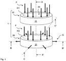
- FIGS. 1 to 9 show several embodiments of a transducer 1 with at least one piezoelectric pickup element 10, 10 ', which is a Force F measures by means of the direct piezoelectric effect and with a resonator element 20 which measures a transverse strain Q by means of a frequency change of a resonance frequency.
- the force F and the transverse strain Q are shown schematically as arrows.
- the force F is introduced into the transducer 1 in a direction of force which is parallel to the longitudinal axis AA '.
- the force F acts in at least one transducer contact region K1, K1 'on the piezoelectric transducer element 10, 10', the transducer contact region K1, K1 'is in the force flow.
- the force F can act directly or indirectly on the piezoelectric pickup element 10, 10 '.
- the force F acts on the resonator element 20 in at least one resonator contact region K2, K2 ', and the resonator contact region K2, K2' also lies in the force flow.
- the force F can act directly or indirectly on the resonator element 20.
- the piezoelectric pickup element 10, 10 ' is in mechanical contact with the resonator element 20 via the resonator contact region K2, K2'.
- the piezoelectric pickup element 10, 10 ' measures the force F directly in the force flow, while the resonator element 20 measures the transverse strain Q caused by the force F in an oscillating region which is outside the force flux.
- the force F causes an elastic deformation of the resonator element 20.
- the elastic deformation of the resonator element 20 is a function of the force F, preferably it is proportional to the magnitude of the force F.
- the transverse strain Q In the resonator 20 occur along the longitudinal axis AA 'a change in length and in the transverse plane BC, the transverse strain Q on.
- a magnitude of the transverse strain Q is a function of the force, preferably it is proportional to the magnitude of the force F.
- the force F is a compressive force
- the force F a tensile force
- the transverse strain Q may be isotropic or anisotropic. Especially with piezoelectric material, the transverse strain Q is anisotropic.
- the piezoelectric pickup element 10, 10 ' is hollow cylindrical (ring, sleeve, etc.).
- the resonator element 20 is cylindrical (disc, round rod, etc.).
- those skilled in the art can also realize other known forms of piezoelectric pickup elements and of resonator elements such as polyhedra, cubes, cuboids, hollow truncated, half-slices, quarter-slices, etc.
- the piezoelectric pickup element 10, 10 ' is made of piezoelectric material 11, 11'.
- the piezoelectric material 11, 11 ' is crystal material such as quartz (SiO 2 single crystal), calcium gallo-germanate (Ca 3 Ga 2 Ge 4 O 14 or CGG), langasite (La 3 Ga 5 SiO 14 or LGS), tourmaline, gallium orthophosphate
- the piezoelectric material 11, 11 ' consists of crystal material of symmetry class m, 32, 3m, 42m, 2m or 23.
- quartz is used as piezoelectric material 11, 11', with the orthogonal axes x, y , z as crystal axes and the axis z as the optical axis.
- An elasticity coefficient s ⁇ ( ⁇ S ⁇ / ⁇ T ⁇ ) of quartz is in a plane xy for different Orientations of the piezoelectric material 11, 11 'in magnitude equal.
- S ⁇ is a mechanical strain tensor in matrix notation referred to
- T ⁇ is a mechanical stress tensor in matrix notation, with tensor indices ⁇ , ⁇ - 1 to 6.
- a thermal coefficient of linear expansion ⁇ of quartz is in the plane xy for different orientations of the piezoelectric Material 11, 11 'same.
- the force F acts on the piezoelectric transducer element 10, 10 'and generates electrical polarization charges on element surfaces of the piezoelectric transducer element 10, 10'.
- the piezoelectric pickup element 10, 10 ' is oriented for the direct piezoelectric effect in the form of the longitudinal effect in such a way that also electrical polarization charges are generated on end faces on which the force F acts.
- the end faces are thus the element surfaces.
- the end faces lie in the transverse plane BC.
- D i denotes an electrical displacement field
- T ⁇ denotes a mechanical stress tensor in matrix notation
- Sensitivity indicates how strongly the first piezoelectric material 11, 11 'on the force F reacts how many electric polarization charges the force F generates.
- the piezoelectric material 11, 11 ' is oriented to the force F such that it has a high sensitivity, preferably a maximum sensitivity for the direct piezoelectric Has effect.
- quartz is used as the piezoelectric material 11, 11 ', with the orthogonal axes x, y, z as crystal axes and the axis z as the optical axis.
- the piezoelectric coefficient d 11 has maximum sensitivity when the piezoelectric pickup element 10, 10 'is cut as an x-ring having an axis x as normal to a plane yz.
- the axis x of the x-ring is parallel to the longitudinal axis AA '.
- the optical axis z of the x-ring lies in the transverse plane BC.
- the resonator element 20 may likewise consist of piezoelectric material 21.
- the piezoelectric pickup element 10, 10 'and the resonator element 20 of the same piezoelectric material 11, 11', 21, whereby the production of the transducer 1 is inexpensive and the piezoelectric pickup element 10, 10 'and the resonator element 20 have substantially similar physical properties .
- the person skilled in the art may consist of a composite of a piezoelectric material and a non-piezoelectric material such as a metal, a nonmetal, a semiconductor, an organic material, an inorganic nonmetallic material, etc.
- the two materials are connected to each other via material connection such as thermocompression bonding, gluing, etc.
- the resonator element 20 can be excited with an excitation frequency of the alternating electric field to at least one resonance frequency in a fundamental tone and n overtones. Resonance is present when the excitation frequency is equal to a mechanical natural frequency of the resonator element 20.
- the resonator element 20 is oriented such that it oscillates as a thickness oscillator or as a length or extensional oscillator or as a bending oscillator or as a surface vibrator or as a thickness shear oscillator.
- the resonator element 20 is operated as a thickness shifter.
- the resonator element 20 is oriented such that two end faces of the cylindrical resonator element 20 move in opposite directions in the transverse plane BC. The end faces lie in the transverse plane BC.
- the transverse strain Q produces a frequency change ⁇ f of the resonant frequency f of the resonator element 20.
- the frequency change ⁇ f is a function of the force F.
- the frequency change ⁇ f is proportional to the magnitude of the transverse strain Q.
- the frequency change ⁇ f Q * K f * (f 2 * ⁇ / n * D) is a function of several parameters.
- the frequency change ⁇ f can thus also be proportional to a Force sensitivity K f be.
- the force sensitivity K f depends on a force introduction angle ⁇ .
- D is a dimension parameter such as a diameter in the transverse plane BC of the piezoelectric material 21.
- ⁇ denotes a device parameter.
- quartz is used as the piezoelectric material 21 of the resonator element 20, with the orthogonal axes x, y, z as crystal axes and the axis z as the optical axis.
- the resonator element 20 is cut as y-disk with the axis y as normal to a plane zx and has a piezoelectric module e 26 and a modulus of elasticity c 66 .
- the axis y of the y-disc is parallel to the longitudinal axis AA '.
- the optical axis z of the y-disk lies in the transverse plane BC. It is also possible to use an AT disk instead of a y-disk as the resonator element 20.
- the AT disk is cut in a plane z'x, with an angle of 35.25 ° between the axis z and an axis z '.
- those skilled in the art may use other known cuts in piezoelectric crystal material such as CT cut, GT cut, BT cut, DT cut, FT cut, etc.
- the transducer 1 has a single piezoelectric transducer element 10.
- the resonator element 20 is arranged with respect to the longitudinal axis AA 'within the piezoelectric transducer element 10.
- the resonator element 20 is arranged spatially between a first piezoelectric material 11 and a second piezoelectric material 11 'of the piezoelectric pickup element 10.
- the transducer 1 has two piezoelectric transducer elements 10, 10 '.
- the resonator element 20 is arranged with respect to the longitudinal axis AA 'between a first piezoelectric pickup element 10 and a second piezoelectric pickup element 10'.
- the resonator element 20 is arranged spatially between a first piezoelectric material 11 of the first piezoelectric pickup element 10 and a second piezoelectric material 11 'of the second piezoelectric pickup element 10'.
- the transducer 1 has a symmetrical construction with respect to the longitudinal axis AA'.
- the resonator element 20 is arranged with respect to the longitudinal axis AA 'between a first piezoelectric material 11 and a second piezoelectric material 11'.
- the first piezoelectric material 11 and the second piezoelectric material 11 ' are identical parts, whereby the production of the transducer 1 is inexpensive.
- Fig. 2, 3rd are identical parts, whereby the production of the transducer 1 is inexpensive.
- the second piezoelectric material 11 ' is mechanically connected to the piezoelectric material 21 of the resonator element 20.
- the mechanical connection via material connection such as welding, diffusion welding, thermocompression bonding, soldering, etc.
- material connection such as welding, diffusion welding, thermocompression bonding, soldering, etc.
- the resonator element 20 is cylindrical with respect to the longitudinal axis AA 'and disposed between a hollow cylindrical first piezoelectric material 11 and a hollow cylindrical second piezoelectric material 11'.
- a first cavity 33 and in the hollow cylinder of the second piezoelectric material 11 ' a second cavity 33' is formed.
- the cavities 33, 33 ' are above and below the resonator element 20.
- a spatial extent of the cavities 33, 33' along the longitudinal axis AA 'and in the transverse plane BC is greater than amplitudes of the mechanical vibrations of the resonator 20.
- the resonator 20 thus has enough Space to vibrate in the cavities 33, 33 'with high quality.
- the mechanical vibrations can take place axially along the longitudinal axis AA '.
- the mechanical vibrations can take place radially in the transverse plane BC.
- the mechanical vibrations can be done as a thickness shear vibration in the transverse plane BC.
- the mechanical vibrations can take place as a combination of an axial and a radial oscillation or as a combination of a radial oscillation and a thickness shear oscillation.
- electrical polarization charges of the piezoelectric material 11, 11 'of the piezoelectric pickup element 10, 10' are taken from electrodes 12, 12 ', 13, 13' and discharged as charge signals to an evaluation unit.
- the electrodes 12, 12 ', 13, 13' are also called charge electrodes 12, 12 ', 13, 13'.
- an alternating electric field is applied as frequency signals to the piezoelectric material 21 of the resonator element 20 via electrodes 22, 23.
- the electrodes 22, 23 are also called frequency electrodes 22, 23.
- the electrodes 12, 12 ', 13, 13', 22, 23 are thin layers of electrically conductive material such as pure metals, nickel alloys, cobalt alloys, iron alloys, etc.
- the electrodes 12, 12 ', 13, 13', 22, 23 are mechanically and electrically connected to the piezoelectric material 11, 11 ', 21.
- the mechanical and electrical connection via material connection such as welding, diffusion bonding, thermocompression bonding, soldering, etc.
- material connection such as welding, diffusion bonding, thermocompression bonding, soldering, etc.
- Such a cohesive connection is inexpensive and long-term stable mechanically and electrically.
- the charge electrodes 12, 12 ', 13, 13' are hollow cylindrical and extend substantially completely over end faces of the piezoelectric pickup element 10, 10 '.
- the frequency electrodes 22, 23 are cylindrical and extend into an oscillating region over end faces of the resonator element 20.
- the oscillating region lies in a central region of the end faces of the resonator element 20, it lies close to the longitudinal axis AA 'penetrating the end faces centrally. In one of the longitudinal axis AA 'radially remote edge region of the end surfaces of the resonator 20 only narrow electrical leads to the frequency electrodes 22, 23 are arranged.
- the piezoelectric material 21 is excited by the frequency electrodes 22, 23 to produce mechanical oscillations and the resonator element 20 oscillates with a high amplitude.
- the force F is introduced into the resonator 20.
- the piezoelectric material 21 is not excited by the frequency electrodes 22, 23 to vibrate mechanically, and the resonator element 20 oscillates at low amplitude, a magnitude of the amplitude decreases at a radial distance from the frequency electrodes 22, 23.
- a radial extent of the edge region is chosen so that a mechanical connection of the piezoelectric transducer element 10, 10 'with the resonator element 20 does not dampen the mechanical vibrations or only to a negligible extent.
- the first and the third embodiment according to Fig. 2, 3rd . 6, 7 has four electrodes 12, 13, 22, 23, the second and fourth embodiments according to Fig. 4, 5 . 8, 9 has six electrodes 12, 12 ', 13, 13', 22, 23.
- a charge electrode 12 is mechanically and electrically connected both to the first piezoelectric material 11 of the piezoelectric pickup element 10 and to the piezoelectric material 21 of the resonator element 20.
- the charge electrode 12 is called on the counter electrode 12.
- a charge electrode 13 is disposed on the first piezoelectric material 11 of the piezoelectric pickup element 10 and serves as an electrical ground and is also called a ground electrode 13.
- the grounding element 13 is electrically connected to a grounded housing 41 of the transducer 1.
- the counterelectrode 12 and the frequency electrodes 22, 23 are in exactly one contacting zone Z near the inclined axis CC 'for electrical and mechanical contact with electrical Ladders easily accessible.
- the transducer 1 requires only three electrical conductors for four electrodes 12, 13, 22, 23.
- the common counterelectrode 12, 12 'and the frequency electrodes 22, 23 are easily accessible in exactly one contacting zone Z near the inclined axis CC' for electrical and mechanical contacting with electrical conductors.
- the transducer 1 requires only three electrical conductors for six electrodes 12, 12 ', 13, 13', 22, 23.
- a charge electrode 13 is mechanically and electrically connected both to the first piezoelectric material 11 of the piezoelectric pickup element 10 and to the piezoelectric material 21 of the resonator element 20.
- the charge electrode 13 is electrically connected to a frequency electrode 23.
- the two electrically interconnected electrodes 13, 23 serve as a common electrical ground and are also called ground electrodes 13, 23.
- a charge electrode 12 is disposed on the piezoelectric material 11, 11 'of the piezoelectric pickup element 10 and is also called a counter electrode 12.
- the ground electrodes 13, 23, the counter electrode 12 and the frequency electrode 22 are easily accessible in exactly one contacting zone Z near the inclined axis CC 'for electrical and mechanical contact with electrical conductors.
- the transducer 1 requires only three electrical conductors for four electrodes 12, 13, 22, 23.
- two charge electrodes 12 ', 13 are mechanically connected to the piezoelectric material 21 of the resonator element 20.
- the two charge electrodes 12 ', 13 are arranged on different end faces of the piezoelectric material 21.
- Two charge electrodes 12, 13 ' are disposed on the piezoelectric material 11, 11' of the piezoelectric pickup elements 10, 10 '.
- a charge electrode 12 'mechanically connected to the piezoelectric material 21 of the resonator element 20 and a charge electrode 12 disposed on the first piezoelectric material 11 of the first piezoelectric pickup element 10 are electrically connected to each other and serve as common counterelectrode 12, 12 '.
- the two counterelectrodes 12, 12 'tap electrical polarization charges with the same sign
- the first piezoelectric material 11 of the first piezoelectric pickup element 10 and the second piezoelectric material 11' of the second piezoelectric pickup element 10 ' are arranged with the same direction of polarization.
- a charge electrode 13 mechanically connected to the piezoelectric material 21 of the resonator element 20 and a charge electrode 13 'disposed on the second piezoelectric material 11' of the second piezoelectric pickup element 10 ' are electrically connected to each other and serve as an electrical ground and are also called ground electrodes 13, 13'
- the two mass element electrodes 13, 13 ' are electrically connected to the grounded housing 41 of the transducer 1.
- the ground electrode 13, the counter electrode 12 'and the frequency electrodes 22, 23 are easily accessible in exactly one contacting zone Z near the inclined axis CC' for electrical and mechanical contact with electrical conductors.
- the transducer 1 requires only three electrical conductors for six electrodes 12, 12 ', 13, 13', 22, 23.
- a structure of the transducer 1 with three electrical conductors for four or six electrodes 12, 12 ', 13, 13', 22 and 23 is space-saving and makes a production of the transducer 1 cost.
- the material bond is made by welding, diffusion welding, thermo-compression, soldering, etc.
- the adhesion takes place by screw connection, clamping connection, etc.
- the transducer 1 has an electrical insulation element 14.
- the electrical insulation element 14 is hollow cylindrical.
- the electrical insulation element 14 is made of electrically insulating and mechanically rigid material such as ceramic, Al 2 O 3 ceramic, sapphire, etc.
- the electrical insulation element 14 is mechanically connected to a counter electrode 12.
- the mechanical connection via material connection such as welding, diffusion bonding, thermocompression bonding, soldering, etc. Such a cohesive connection is inexpensive and mechanically long-term stability.
- the frequency electrodes 22, 23 of the resonator element 20 are electrically connected to an oscillator circuit of the evaluation unit.
- the frequency change .DELTA.f is determined with the oscillator circuit.
- the evaluation unit determines the transverse strain from the determined frequency change ⁇ f Q.
- the oscillator circuit is a Colpitts circuit. Typical resonance frequencies are in the range of a few kHz to several MHz, typical frequency changes ⁇ f are in the range of 2 Hz / N to 100 Hz / N.
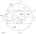
- the 10 and 11 show the force sensitivity K f as a function of the force introduction angle ⁇ .
- This force sensitivity K f applies to a resonator element 20 oscillating in the cavity 33, 33 'according to the embodiments according to FIG Fig. 1 to 9 ,
- the force sensitivity K f is maximum and normalized to 100%.
- the force sensitivity K f is zero or 0%.
- the force sensitivity K f is minimum or -60%.
- a force introduction angle range ⁇ extends beyond 90 ° from the transverse axis BB 'to the oblique axis CC', then Fig. 10 a sum of the force sensitivities K f a total power sensitivity K fG of 10%.
- a force introduction angle range ⁇ is limited. For a first force introduction angle range ⁇ 1 over 45 ° from the transverse axis BB 'to the oblique axis CC', the sum of the force sensitivities K f results in a first average force sensitivity K fM1 of 50%.
- An optimal adjustment of the force introduction angle range ⁇ can be achieved with at least one force application element 30, 30 '.
- the force F acts on the force application element 30, 30 'and is forwarded by the force application element 30, 30' into the piezoelectric transducer element 10, 10 'and the resonator element 20.
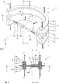
- the Fig. 12 and 13 show in perspective view a first and a second embodiment of a hollow spherical segment-shaped force application element 30, 30 '.
- the Fig. 14 and 15 show in plan view a third and a fourth embodiment of a hollow truncated cone-shaped force application element 30, 30 '.
- the force application element 30, 30 ' may also be hollow cylindrical, hollow pyramidal, etc.
- the force application element 30, 30 ' consists of mechanically rigid material such as pure metals, nickel alloys, cobalt alloys, iron alloys, ceramics, etc.
- the force application element 30, 30 ' is a hollow body which has a cover surface 31, 31', a lateral surface 32, 32 'and a cavity 33, 33'.
- the resonator element 20 is arranged in the cavity 33, 33 '.
- the cavity 33, 33 ' extends both in the force application element 30, 30' and in the piezoelectric transducer element 10, 10 '.
- Top surface 31, 31 'and lateral surface 32, 32' are mechanically interconnected and enclose the cavity 33, 33 '.
- the force F engages along the longitudinal axis AA 'on the top surface 31, 31' and is forwarded by the top surface 31, 31 'in the lateral surface 32, 32'.
- the lateral surface 32, 32 ' has at least one recessed area 34, 34', which extends to the cavity 33, 33 'and prevents the transmission of the force F in the lateral surface 32, 32'.
- the outer surface 32, 32 ' has at least one non-recessed area 35, 35', and only the non-recessed area 35, 35 'passes the force F further.
- the hollow body has a base surface 36, 36 'at an end remote from the top surface 31, 31'.
- Top surface 31, 31 'and base 36, 36' are mechanically connected to each other via the lateral surface 32, 32 '.
- Top surface 31, 31 ', lateral surface 32, 32' and base 36, 36 ' are preferably in one piece.
- Top surface 31, 31 'and base 36, 36' are parallel to each other in the transverse plane BC.
- the non-recessed region 35, 35 'of the lateral surface 32, 32' and the base surface 36, 36 ' form at least one force transmission angle range ⁇ , ⁇ 1 , ⁇ 2 in the transverse plane BC.
- the recessed area 34, 34 ' is preferably window-shaped.
- the recessed area 34, 34 ' is arranged in a lower area of the lateral surface 32, 32' with respect to the longitudinal axis AA '.
- the recessed area 34, 34 ' forms a large part of the lateral surface 32, 32'.
- the force application element 30, 30 ' has four first force introduction angle ranges ⁇ 1 of 45 ° each.
- the force application element 30, 30 ' has four second force introduction angle ranges ⁇ 2, each of 30 °.
- Each two first or second force introduction angle ranges ⁇ 1 , ⁇ 2 are limited by a recessed area 34, 34 ', so that the force F only over the first or second Force introduction angle ranges ⁇ 1 , ⁇ 2 is forwarded.
- each force-engaging element 30, 30 ' has two recessed regions 34, 34', which are rotated at an angle of 180 ° to one another with respect to the longitudinal axis AA '.
- the first or second force introduction angle range ⁇ 1 , ⁇ 2 is partially limited in such a way that in sum an average force sensitivity K fM1 , K fM2 is close to the maximum of 100% of the power sensitivity K f .
- the smaller the first or second force introduction angle range ⁇ 1 , ⁇ 2 the greater is a local pressure in the piezoelectric transducer element 10, 10 'and in the resonator element 20.
- the magnitude of the first or second force introduction angle range ⁇ 1 , ⁇ 2 and thus of the local pressure in piezoelectric transducer element 10, 10 'and in the resonator 20 can be selected depending on the compressive strength of the piezoelectric transducer element 10, 10' and the resonator 20.
- Fig. 16 shows a section of the transducer 1 after FIGS. 2 and 3 with a force application element 30 after Fig. 14 or 15
- Fig. 17 shows a section of the transducer 1 after 8 and 9 with two force application elements 30, 30 'after Fig. 14 or 15
- the two force application elements 30, 30 ' are identical parts, which common parts transmit the force F symmetrically to the piezoelectric transducer element 10, 10' and to the resonator element 20.
- the piezoelectric transducer element 10, 10 'and the resonator element 20 are mechanically connected to the lateral surface 32, 32'.
- This mechanical connection is preferably indirect.
- the piezoelectric pickup element 10, 10 ' is mechanically connected to the force application element 30, 30' indirectly via the pickup contact region K1, K1 'and the base surface 36, 36'.
- the resonator element 20 is in the embodiments according to Fig. 16 and 17 indirectly mechanically connected via the resonator contact region K2, K2 'to the piezoelectric pickup element 10, 10', which in turn is mechanically connected to the force application element 30, 30 'via the pickup contact region K1, K1' and the base surface 36, 36 '.
- the mechanical connection via material bond such as welding, diffusion bonding, thermocompression bonding, soldering, etc.
- the force F acts both on a first force application element 30 and on the piezoelectric transducer element 10.
- the force F acts once indirectly on the first force application element 30 on the piezoelectric transducer element 10 and it attacks once directly on a Aufnado réelle Scheme K1 'on the piezoelectric transducer element 10.
- Nach Fig. 17 engages the force F on the first force application element 30 and is transmitted via a first base 36 and the Aufsacrificingtive Quilt K1 in the first piezoelectric pickup element 10 and the force F acts on a second force application element 30 'and is a second base 36' and the Aufsacrificingcloth Scheme K1 'forwarded to the second piezoelectric pickup element 10'.
- the force F attacks twice indirectly via force application elements 30, 30 'to piezoelectric transducer elements 10, 10'.
- the force F is thus forwarded by the piezoelectric pickup element 10, 10 'into the resonator element 20.
- Top surface 31, 31 'and base 36, 36' are parallel to each other in the transverse plane BC.
- the longitudinal axis AA ' is perpendicular to the transverse plane BC.
- the top surface 31, 31 ' is preferably circular and has a constant outer radius or maximum distance B1 of the top surface 31, 31' to the longitudinal axis AA 'on.
- the base surface 36, 36 ' is preferably annular and has a constant outer radius or maximum distance B2 of the base 36, 36' to the longitudinal axis AA '.
- the maximum distance B2 is greater than the maximum distance B1.
- the force F is thus forwarded in the lateral surface 32, 32 'away from the longitudinal axis AA'.
- the forwarding of the force F takes place in a curved section of the non-recessed area 35, 35 'of the lateral surface 32, 32'.
- the forwarding of the force F takes place from the cover surface 31, 31 'to the resonator contact region K2, K2'.
- A2 denotes a length along the longitudinal axis AA 'of the top surface 31, 31' to the resonator contact region K2, K2 '.
- the force F acting on the top surface 31, 31 ' causes an increased transverse strain Q in the resonator element 20.
- With the increased transverse strain Q increases also the frequency change generated by the force F.
- the dependence of the force sensitivity K f on the force introduction angle ⁇ also influences a magnitude of a thermal expansion coefficient ⁇ of the piezoelectric material 11, 11 ', 21.
- Nach Fig. 18 is the thermal expansion coefficient ⁇ at maximum power sensitivity K f with a force introduction angle ⁇ along the transverse axis BB 'maximum and normalized to 100%.
- the thermal expansion coefficient ⁇ of the piezoelectric material 11, 11', 21 is minimal and normalized to 55%.
- the sensor 1 is permanently exposed to temperatures of 200 ° C and higher during operation.
- the piezoelectric material 11, 11 ', 21 and the force application element 30, 30' may extend differently in length.
- the force application element 30, 30 ' has a thermal coefficient of linear expansion ⁇ 30 .
- the coefficient of thermal expansion ⁇ 30 and the mean coefficients of thermal expansion (K f * ⁇ ) M 1 , (K f * ⁇ ) M 2
- the first or second weighted thermal expansion coefficient ⁇ M1 , ⁇ M2 of the piezoelectric material 11, 11 ', 21 is substantially equal to thermal expansion coefficient ⁇ 30 of the force application element 30, 30 '.
- quartz is used as the piezoelectric material 11, 11 ', 21, with a maximum coefficient of thermal expansion ⁇ of 13.7 * 10 -6 K -1 , which corresponds to the 100% normalization in FIGS. 18 and 19 corresponds to a minimum thermal expansion coefficient ⁇ of 7.5 * 10 -6 K -1 , which corresponds to the 55% normalization in FIGS. 18 and 19 equivalent.
- a force-applying element 30, 30 'made of steel has a thermal expansion coefficient ⁇ 30 of 13.0 * 10 -6 K -1 .
- the piezoelectric material 11 , 11 ', 21 a second weighted thermal expansion coefficient ⁇ M2 - 13 * 10 -6 K -1 , which is substantially equal to the thermal expansion coefficient ⁇ 30 of the force application element 30, 30'.
- the resonator element 20 measures a temperature T using the inverse piezoelectric effect.
- ⁇ f T denotes a temperature-dependent frequency change.
- the frequency change ⁇ f T is determined by the oscillator circuit of the evaluation unit.
- the evaluation unit determines from the determined temperature-dependent change in frequency .DELTA.f T is the temperature T.
- quartz is used as a piezoelectric material 21 of the resonator element 20 with resonant frequencies in the range of several kHz to several MHz and a temperature-dependent change in frequency .DELTA.f T in the range of 20Hz / K to 200Hz / K.
- Fig. 20 shows the ready-to-mount transducer 1 Fig. 1 to 9 with a force application element 30, 30 'after FIGS. 14 to 17 ,
- the transducer 1 is mounted in a housing 41 under vacuum.
- the housing 41 is cylindrical.
- At least one force application element 30, 30 ' projects on one end face of the housing 41 with a cover surface 31, 31' out of the housing 41.
- Each end face has a hollow cylindrical cover 42. Housing 41 and cover 42 protect the transducer 1 from harmful external influences such as dirt, moisture, mechanical shock, etc.
- Housing 41 and cover 42 are made of mechanically resistant material such as pure metals, nickel alloys, cobalt alloys, iron alloys, etc.
- the force application element 30, 30 'Is mechanically connected by means of the cover 42 with the housing 41.
- the cover 42 is mechanically connected to the housing 41 via a radially outer edge with respect to the longitudinal axis AA '.
- the mechanical connection via material connection such as welding, diffusion bonding, thermocompression bonding, soldering, etc.
- the cover 42 is mechanically connected via a with respect to the longitudinal axis AA 'radially inner edge with the force application elements 30, 30'.
- the mechanical connection via material connection such as welding, diffusion bonding, thermocompression bonding, soldering, etc.
- the cover 42 is thin, the cover 42 is 0.3mm, preferably 0.2mm, preferably 0.1mm thin. The thinner the cover 42, the lower the force shunt to the housing 41.
- Charge signals of the charge electrodes 12, 12 ', 13 and 13' can be derived via electrical conductors to an electrical connection 43 to the evaluation unit.
- Frequency signals from the evaluation unit can be applied via the electrical connection 43 via electrical conductors to the frequency electrodes 22, 23.
- the evaluation unit is electrically connectable via a plug with cable to the electrical connection 43.
- the electrical connection 43 is arranged in an opening of a side wall of the housing 41.
- the electrical connection 43 is mechanically connected to the housing 41.
- the mechanical connection via material bond such as welding, diffusion bonding, thermocompression bonding, soldering, etc.
- the electrical and mechanical contacting of the electrodes 12, 12 ', 13, 13', 22 and 23 with electrical conductors is easy to accomplish in exactly one contacting zone Z.
- the transducer 1 after Fig. 1 to 9 before it is placed in the housing 41 electrically and mechanically contacted with stripped ends of the electrical conductors. Then, the transducer 1 is placed in the housing 41 and electrically and mechanically contacted with the transducer 1 electrical conductors are passed through the opening in the side wall of the housing 41 to the outside and electrically and mechanically by means of adhesion and / or adhesion to the electrical connection 43rd contacted.
- the material bond is made by welding, diffusion welding, thermocompression, soldering, etc.
- the adhesion is achieved by screw connection, clamp connection, etc.
- the mechanical connections between the housing 41 and the covers 42, between the covers 42 and the force application elements 30, 30 ', and between the housing 41 and the electrical connection 43 are pressure-tight.
Landscapes
- Physics & Mathematics (AREA)
- General Physics & Mathematics (AREA)
- Acoustics & Sound (AREA)
- Measuring Fluid Pressure (AREA)
Priority Applications (6)
| Application Number | Priority Date | Filing Date | Title |
|---|---|---|---|
| EP16201405.4A EP3330687A1 (fr) | 2016-11-30 | 2016-11-30 | Transducteur destiné à mesurer simultanément une force qui peut être tant dynamique que statique |
| US16/462,097 US11209325B2 (en) | 2016-11-30 | 2017-10-05 | Measurement transducer for simultaneously measuring a force that can be both dynamic and static |
| CN201780074190.3A CN110036267B (zh) | 2016-11-30 | 2017-10-05 | 同时测量既可以是动态的也可以是静态的力的测量传感器 |
| JP2019528890A JP6806900B2 (ja) | 2016-11-30 | 2017-10-05 | 動的にも静的にもなり得る力を同時に測定するための測定センサ |
| PCT/EP2017/075308 WO2018099633A1 (fr) | 2016-11-30 | 2017-10-05 | Capteur de mesure pour mesurer à la fois une force qui peut être aussi bien dynamique que statique |
| EP17778307.3A EP3548857B1 (fr) | 2016-11-30 | 2017-10-05 | Transducteur destiné à mesurer simultanément une force qui peut être tant dynamique que statique |
Applications Claiming Priority (1)
| Application Number | Priority Date | Filing Date | Title |
|---|---|---|---|
| EP16201405.4A EP3330687A1 (fr) | 2016-11-30 | 2016-11-30 | Transducteur destiné à mesurer simultanément une force qui peut être tant dynamique que statique |
Publications (1)
| Publication Number | Publication Date |
|---|---|
| EP3330687A1 true EP3330687A1 (fr) | 2018-06-06 |
Family
ID=57442564
Family Applications (2)
| Application Number | Title | Priority Date | Filing Date |
|---|---|---|---|
| EP16201405.4A Withdrawn EP3330687A1 (fr) | 2016-11-30 | 2016-11-30 | Transducteur destiné à mesurer simultanément une force qui peut être tant dynamique que statique |
| EP17778307.3A Active EP3548857B1 (fr) | 2016-11-30 | 2017-10-05 | Transducteur destiné à mesurer simultanément une force qui peut être tant dynamique que statique |
Family Applications After (1)
| Application Number | Title | Priority Date | Filing Date |
|---|---|---|---|
| EP17778307.3A Active EP3548857B1 (fr) | 2016-11-30 | 2017-10-05 | Transducteur destiné à mesurer simultanément une force qui peut être tant dynamique que statique |
Country Status (5)
| Country | Link |
|---|---|
| US (1) | US11209325B2 (fr) |
| EP (2) | EP3330687A1 (fr) |
| JP (1) | JP6806900B2 (fr) |
| CN (1) | CN110036267B (fr) |
| WO (1) | WO2018099633A1 (fr) |
Cited By (2)
| Publication number | Priority date | Publication date | Assignee | Title |
|---|---|---|---|---|
| CN113091595A (zh) * | 2021-04-02 | 2021-07-09 | 浙江省计量科学研究院 | 一种工具式应变传感器动静态测量装置 |
| EP3859294A1 (fr) * | 2020-01-29 | 2021-08-04 | Piezocryst Advanced Sensorics GmbH | Élément capteur piezoélectrique structuré |
Families Citing this family (5)
| Publication number | Priority date | Publication date | Assignee | Title |
|---|---|---|---|---|
| EP3285057B1 (fr) * | 2016-08-17 | 2023-06-07 | Kistler Holding AG | Capteur de pression élevée |
| AT520901B1 (de) * | 2018-01-24 | 2019-11-15 | Avl List Gmbh | Messvorrichtung und Verfahren zur Bestimmung einer Kraft und/oder eines Drehmoments an einer drehmomentübertragenden Welle |
| WO2019226498A1 (fr) * | 2018-05-19 | 2019-11-28 | The Regents Of The University Of California | Résonateurs à disque creux à force de couplage électromécanique élevée |
| CN113237578B (zh) * | 2021-05-08 | 2022-09-30 | 大连理工大学 | 一种基于全剪切效应石英晶片的多维力/力矩测量方法 |
| CN114932568B (zh) * | 2022-05-07 | 2023-07-21 | 之江实验室 | 一种柔性可动静态压力感知的电子皮肤及其制备方法 |
Citations (5)
| Publication number | Priority date | Publication date | Assignee | Title |
|---|---|---|---|---|
| EP0065511A1 (fr) | 1981-05-20 | 1982-11-24 | List, Hans | Instrument de mesure avec un élément de détection piézoélectrique |
| US4546658A (en) * | 1984-02-24 | 1985-10-15 | General Electric Company | Piezoelectric force/pressure sensor |
| DE3705471A1 (de) * | 1987-02-20 | 1988-09-01 | Mettler Instrumente Ag | Kraftmessgeraet |
| WO2012164016A2 (fr) * | 2011-06-03 | 2012-12-06 | Piezocryst Advanced Sensorics Gmbh | Capteur de mesure de pression et/ou de force |
| WO2015139149A1 (fr) * | 2014-03-21 | 2015-09-24 | Kistler Holding Ag | Élément de mesure piézoélectrique servant à mesurer la pression dynamique et statique et/ou la température |
Family Cites Families (4)
| Publication number | Priority date | Publication date | Assignee | Title |
|---|---|---|---|---|
| JPH0610638B2 (ja) * | 1986-12-05 | 1994-02-09 | 日本電気株式会社 | 積層型圧電素子 |
| CN101368989B (zh) * | 2007-08-17 | 2010-11-10 | 中国科学院声学研究所 | 用于切向压电应变常数d15测量中使用的切向加力部件 |
| CN201259519Y (zh) * | 2007-09-24 | 2009-06-17 | 中国科学院声学研究所 | 一种压电材料切向压电应变常数准静态法测量系统 |
| US9970831B2 (en) * | 2014-02-10 | 2018-05-15 | Texas Instruments Incorporated | Piezoelectric thin-film sensor |
-
2016
- 2016-11-30 EP EP16201405.4A patent/EP3330687A1/fr not_active Withdrawn
-
2017
- 2017-10-05 JP JP2019528890A patent/JP6806900B2/ja active Active
- 2017-10-05 WO PCT/EP2017/075308 patent/WO2018099633A1/fr not_active Ceased
- 2017-10-05 EP EP17778307.3A patent/EP3548857B1/fr active Active
- 2017-10-05 US US16/462,097 patent/US11209325B2/en active Active
- 2017-10-05 CN CN201780074190.3A patent/CN110036267B/zh active Active
Patent Citations (5)
| Publication number | Priority date | Publication date | Assignee | Title |
|---|---|---|---|---|
| EP0065511A1 (fr) | 1981-05-20 | 1982-11-24 | List, Hans | Instrument de mesure avec un élément de détection piézoélectrique |
| US4546658A (en) * | 1984-02-24 | 1985-10-15 | General Electric Company | Piezoelectric force/pressure sensor |
| DE3705471A1 (de) * | 1987-02-20 | 1988-09-01 | Mettler Instrumente Ag | Kraftmessgeraet |
| WO2012164016A2 (fr) * | 2011-06-03 | 2012-12-06 | Piezocryst Advanced Sensorics Gmbh | Capteur de mesure de pression et/ou de force |
| WO2015139149A1 (fr) * | 2014-03-21 | 2015-09-24 | Kistler Holding Ag | Élément de mesure piézoélectrique servant à mesurer la pression dynamique et statique et/ou la température |
Cited By (3)
| Publication number | Priority date | Publication date | Assignee | Title |
|---|---|---|---|---|
| EP3859294A1 (fr) * | 2020-01-29 | 2021-08-04 | Piezocryst Advanced Sensorics GmbH | Élément capteur piezoélectrique structuré |
| CN113091595A (zh) * | 2021-04-02 | 2021-07-09 | 浙江省计量科学研究院 | 一种工具式应变传感器动静态测量装置 |
| CN113091595B (zh) * | 2021-04-02 | 2023-03-24 | 浙江省计量科学研究院 | 一种工具式应变传感器动静态测量装置 |
Also Published As
| Publication number | Publication date |
|---|---|
| EP3548857A1 (fr) | 2019-10-09 |
| CN110036267B (zh) | 2021-06-18 |
| US20200271531A1 (en) | 2020-08-27 |
| CN110036267A (zh) | 2019-07-19 |
| EP3548857B1 (fr) | 2022-06-29 |
| JP6806900B2 (ja) | 2021-01-06 |
| JP2019536046A (ja) | 2019-12-12 |
| US11209325B2 (en) | 2021-12-28 |
| WO2018099633A1 (fr) | 2018-06-07 |
Similar Documents
| Publication | Publication Date | Title |
|---|---|---|
| EP3548857B1 (fr) | Transducteur destiné à mesurer simultanément une force qui peut être tant dynamique que statique | |
| EP3548856B1 (fr) | Transducteur de mesure d'une force | |
| DE3878473T3 (de) | Wandler für Flüssigkeiten. | |
| DE3741568C2 (fr) | ||
| EP0065511B1 (fr) | Instrument de mesure avec un élément de détection piézoélectrique | |
| EP2810026B1 (fr) | Dispositif pour déterminer et/ou surveiller une variable de processus | |
| US2558563A (en) | Piezoelectric strain gauge | |
| DE2801969C2 (de) | Sensor für Schwingungen | |
| DE69105809T2 (de) | Druckaufnehmer mit schwingendem Element. | |
| CN107543637B (zh) | 压电换能器 | |
| WO1992021945A1 (fr) | Dispositif pour la determination et/ou le controle d'un niveau determine dans un recipient | |
| DE1929478A1 (de) | Piezomesszelle | |
| EP3120123B1 (fr) | Élément de mesure piézoélectrique servant à mesurer la pression dynamique et statique et/ou la température | |
| DE2840286A1 (de) | Schwingdrahtinstrument zur messung eines differenzdruckes | |
| DE102019132021B4 (de) | Vibrationssensor mit integrierter Temperaturerfassung mit einer in Schwingung versetzbaren Membran | |
| WO2025011941A1 (fr) | Capteur de vibrations | |
| AT513634B1 (de) | MEMS-Sensor zur Detektion von Umgebungsparametern | |
| DE102020131591B4 (de) | Vibrationssensor mit kapazitiver Schwingungsmessung | |
| DE102004060903A1 (de) | Vorrichtung zur Erfassung von physikalischen Eigenschaften eines Gases oder eines Gasgemisches mittels eines Hochfrequenz-Resonators | |
| DE102024120080A1 (de) | Vibrationssensor | |
| EP0524381A1 (fr) | Capteur fabriqué en microtechnique | |
| DE3008780A1 (de) | Piezoelektrischer klopfsensor |
Legal Events
| Date | Code | Title | Description |
|---|---|---|---|
| PUAI | Public reference made under article 153(3) epc to a published international application that has entered the european phase |
Free format text: ORIGINAL CODE: 0009012 |
|
| AK | Designated contracting states |
Kind code of ref document: A1 Designated state(s): AL AT BE BG CH CY CZ DE DK EE ES FI FR GB GR HR HU IE IS IT LI LT LU LV MC MK MT NL NO PL PT RO RS SE SI SK SM TR |
|
| AX | Request for extension of the european patent |
Extension state: BA ME |
|
| STAA | Information on the status of an ep patent application or granted ep patent |
Free format text: STATUS: THE APPLICATION HAS BEEN WITHDRAWN |
|
| 18W | Application withdrawn |
Effective date: 20181107 |