EP3330733B1 - Capteur radar pour un véhicule et procédé d'assemblage d'un capteur radar - Google Patents
Capteur radar pour un véhicule et procédé d'assemblage d'un capteur radar Download PDFInfo
- Publication number
- EP3330733B1 EP3330733B1 EP17202549.6A EP17202549A EP3330733B1 EP 3330733 B1 EP3330733 B1 EP 3330733B1 EP 17202549 A EP17202549 A EP 17202549A EP 3330733 B1 EP3330733 B1 EP 3330733B1
- Authority
- EP
- European Patent Office
- Prior art keywords
- radar sensor
- radome
- radar
- contact
- clamp
- Prior art date
- Legal status (The legal status is an assumption and is not a legal conclusion. Google has not performed a legal analysis and makes no representation as to the accuracy of the status listed.)
- Active
Links
Images


Classifications
-
- G—PHYSICS
- G01—MEASURING; TESTING
- G01S—RADIO DIRECTION-FINDING; RADIO NAVIGATION; DETERMINING DISTANCE OR VELOCITY BY USE OF RADIO WAVES; LOCATING OR PRESENCE-DETECTING BY USE OF THE REFLECTION OR RERADIATION OF RADIO WAVES; ANALOGOUS ARRANGEMENTS USING OTHER WAVES
- G01S7/00—Details of systems according to groups G01S13/00, G01S15/00, G01S17/00
- G01S7/02—Details of systems according to groups G01S13/00, G01S15/00, G01S17/00 of systems according to group G01S13/00
- G01S7/027—Constructional details of housings, e.g. form, type, material or ruggedness
-
- G—PHYSICS
- G01—MEASURING; TESTING
- G01S—RADIO DIRECTION-FINDING; RADIO NAVIGATION; DETERMINING DISTANCE OR VELOCITY BY USE OF RADIO WAVES; LOCATING OR PRESENCE-DETECTING BY USE OF THE REFLECTION OR RERADIATION OF RADIO WAVES; ANALOGOUS ARRANGEMENTS USING OTHER WAVES
- G01S13/00—Systems using the reflection or reradiation of radio waves, e.g. radar systems; Analogous systems using reflection or reradiation of waves whose nature or wavelength is irrelevant or unspecified
- G01S13/88—Radar or analogous systems specially adapted for specific applications
- G01S13/93—Radar or analogous systems specially adapted for specific applications for anti-collision purposes
- G01S13/931—Radar or analogous systems specially adapted for specific applications for anti-collision purposes of land vehicles
-
- H—ELECTRICITY
- H01—ELECTRIC ELEMENTS
- H01Q—ANTENNAS, i.e. RADIO AERIALS
- H01Q1/00—Details of, or arrangements associated with, antennas
- H01Q1/27—Adaptation for use in or on movable bodies
- H01Q1/32—Adaptation for use in or on road or rail vehicles
- H01Q1/3208—Adaptation for use in or on road or rail vehicles characterised by the application wherein the antenna is used
- H01Q1/3233—Adaptation for use in or on road or rail vehicles characterised by the application wherein the antenna is used particular used as part of a sensor or in a security system, e.g. for automotive radar, navigation systems
-
- H—ELECTRICITY
- H01—ELECTRIC ELEMENTS
- H01Q—ANTENNAS, i.e. RADIO AERIALS
- H01Q1/00—Details of, or arrangements associated with, antennas
- H01Q1/42—Housings not intimately mechanically associated with radiating elements, e.g. radome
-
- H—ELECTRICITY
- H01—ELECTRIC ELEMENTS
- H01Q—ANTENNAS, i.e. RADIO AERIALS
- H01Q1/00—Details of, or arrangements associated with, antennas
- H01Q1/52—Means for reducing coupling between antennas; Means for reducing coupling between an antenna and another structure
- H01Q1/526—Electromagnetic shields
-
- H—ELECTRICITY
- H01—ELECTRIC ELEMENTS
- H01Q—ANTENNAS, i.e. RADIO AERIALS
- H01Q17/00—Devices for absorbing waves radiated from an antenna; Combinations of such devices with active antenna elements or systems
Definitions
- the invention relates to a radar sensor for a vehicle, having at least one radar sensor housing in which at least one radar antenna is arranged, the radar sensor housing having at least one basic housing part with an installation side for at least one radar antenna and a radome with which the installation side is closed and through which signals transmitted by the at least one radar antenna and / or signals to be received can pass through during operation of the radar sensor, the radar sensor housing having a plurality of elastic clamp elements with which the radome is attached to the at least one base housing part.
- the invention also relates to a method for assembling a radar sensor for a vehicle.
- the radar device comprises a housing which has a first housing part and a second housing part, transmitter and receiver means, at least one carrier part to which the transmitter and receiver means are attached.
- the at least one support part is clamped between the first housing part and the second housing part.
- the radar device has a number of fastening clips suitable for providing a releasable clamping connection between the first housing part, the at least one carrier part and the second housing part. Similar radars are in DE 197 39 298 C1 , DE 199 41 931 A1 , EP 1 762 860 A1 and XP55684751.
- the invention is based on the object of designing a radar sensor and a method of the type mentioned at the outset, in which the radar sensor can be assembled more easily, in particular the radome can be mechanically fastened to the basic housing part more easily.
- a radome is a closed protective cover that protects radar antennas from external mechanical and chemical influences such as wind or rain.
- radomes it is known that materials are used which are particularly permeable to radar signals.
- At least one clamp element is preassembled on the radome.
- the at least one clamp element can thus be arranged on the radome in a captive manner.
- the at least one clamp element can be mounted together with the radome.
- assembly work in particular a number of components required on an assembly line, can be reduced.
- the radar sensor can be set up without additional welding, soldering, gluing and / or screwing processes.
- the radome and the at least one basic housing part which can also consist of different materials, can be connected to one another in a stable manner.
- the elastic clamp elements a mechanical basic tension can be realized with which the at least one radar antenna can be clamped and fixed.
- at least one of the clip elements can be implemented as a spring element. Spring elements can be designed to be elastic.
- At least one clamp element comprises or consists of spring steel.
- Spring steel can be processed easily and is flexible and flexible.
- the at least one basic housing part can advantageously comprise or consist of metal, in particular aluminum. In this way, a mechanically stable radar sensor housing can be realized.
- the radome can in particular comprise or consist of thermoplastic plastic, in particular polybutylene terephthalate (PBT) and / or polyamide (PA).
- thermoplastic plastic in particular polybutylene terephthalate (PBT) and / or polyamide (PA).
- PBT polybutylene terephthalate
- PA polyamide
- the radome can be transparent to the radar signals.
- housing parts made of plastic can give way to pressures acting on them over time. This can be compensated for by the elasticity of the clamp elements.
- the clamp connection according to the invention can prevent the connection between the at least one basic housing part and the radome from loosening over time.
- the invention can be used in a vehicle, in particular a motor vehicle.
- the invention can advantageously be used in a land vehicle, in particular a passenger car, truck, bus, motorcycle or the like.
- the invention can also be used in autonomous or at least partially autonomous vehicles.
- the radar sensor can advantageously be connected to or part of at least one electronic control device of the vehicle, in particular a driver assistance system and / or a chassis control and / or a driver information device.
- the object data recorded with the radar sensor in particular the distance, orientation and / or relative speed of an object relative to the vehicle, can be transmitted to the control device and used to influence driving functions, in particular the speed, a braking function, a steering function and / or an output an information and / or warning signal, in particular for the driver.
- the radar sensor in particular the radar antenna, can advantageously be designed for use in a radar band between 76 GHz and 81 GHz.
- the radar sensor in particular an antenna on a ceramic substrate, can advantageously be designed for use in what is known as an automotive radar band. In this way, the radar sensor can be used in the automotive sector.
- one of the clamp elements is connected to the radome in the region of one of its ends and into the material embedded in the radome.
- the at least one clamp element can, in particular, be releasably connected to the at least one base housing part with a section facing away from the connected end.
- At least one end of the at least one clip element can be cast into the material of the radome.
- the at least one clamp element can already be embedded in the material of the radome during the manufacture of the radome using a plastic molding process, in particular an injection and / or casting process.
- At least one clamp element has at least one S-shaped bend.
- the at least its clip element can be correspondingly elastically bent, in particular for closing and / or opening the clip connection.
- the at least one clamp element can be stretched elastically.
- the at least one clamp element can automatically resume its original shape due to its restoring force.
- a corresponding clamping force can thus be generated due to the spring action, with which the radome can be pressed against the at least one basic housing part and / or optionally against the at least one radar antenna.
- At least one of the clip elements can have at least one latching section.
- the at least one latching section can latch with a corresponding latching section on the housing side on the side of the basic housing part.
- the clamp connection can be secured by means of a latching connection.
- such a latching connection can be designed to be detachable. In this way, the radar sensor housing can be opened again if necessary, in particular for maintenance purposes.
- At least one of the clip elements can advantageously have a locking eyelet.
- a corresponding latching lug can be arranged on the side of the basic housing part. The latch on the housing side can be used to close and Lock the clamp connection in the locking eyelet of the at least one clamp element.
- At least one of the clip elements can be arranged to be accessible from outside the radar sensor housing. In this way, the at least one clamp element can be actuated from the outside.
- the at least one clamp element can have at least one actuation section.
- the at least one clamp element can be actuated to open and / or close and, in doing so, be bent elastically accordingly.
- the at least one clamp element has at least one S-shaped bend. In this way, the bending characteristics of the at least one clamp element can be improved.
- the at least one actuating section can advantageously be arranged on an S-shaped bend of the at least one clamp element.
- By exerting appropriate pressure on the S-shaped bend it can be stretched and the at least one clamp element can thus be lengthened.
- a distance between the end fastened in the radome and a fastening section for the basic housing part, in particular a latching section can be increased.
- the fastening section can be brought into connection with a corresponding fastening section on the side of the at least one base housing part.
- a possible latching section can thus be pushed or slipped over a corresponding latching section on the housing side and then enter into a secure latching connection with the at least one clamp element due to the elastic restoring force of the latter.
- the at least one actuation section can advantageously be designed to engage at least one tool. In this way, the action of force on the at least one actuation section can be improved.
- a plurality of clamp elements can be distributed circumferentially with respect to a direction of assembly of the radome with the at least one basic housing part. In this way, the radome can be connected more uniformly circumferentially to the at least one basic housing part and pressed against it.
- the radome can have at least one clamping element for fixing at least one radar antenna.
- the at least one clamping element of the radome can advantageously be part of a connection device for at least one radar antenna.
- the at least one radar antenna can be fixed in the radar sensor housing with the aid of the radome.
- the at least one radar antenna can be automatically clamped with the corresponding at least one clamping element when the radome is mounted on a base housing part of the radar sensor.
- the radar sensor housing can be connected to the radome in one operation and, at the same time, the at least one radar antenna can be permanently fixed in the radar sensor housing.
- the at least one radar antenna can advantageously be a ceramic substrate with at least one radar antenna.
- the ceramic substrate with the radar antenna can have a plate-shaped ceramic substrate which carries at least one electrical / electronic functional component.
- the radar sensor can advantageously have at least one connection device for the at least one radar antenna.
- the at least one connection device can advantageously have at least one device for fixing the at least one radar antenna, in particular on a circuit board.
- the at least one device for fixing can advantageously have at least one clamping element of a clamping device for fixing the at least one radar antenna.
- the at least one connection device can have at least one electrical contact device for the electrical connection of the at least one electrical / electronic Have functional component in particular with the circuit board.
- the at least one electrical contact device can have at least one at least partially elastic electrical contact element with at least one contact section for making electrical contact with at least one electrical contact area on the side of the at least one radar antenna.
- the at least one radar antenna can be pressed purely mechanically against at least one contact section of at least one electrical contact element of the connection device and fixed with the at least one clamping device. With the at least one clamping device, the at least one radar antenna can be fixed against slipping, in particular in a plane, and at the same time the electrical contacts with the at least one contact section can be ensured.
- the at least one contact section can have an electrically conductive surface which can come into electrically conductive contact with an electrically conductive surface of the at least one electrical contact area on the side of the at least one radar antenna. The electrical contact can be ensured solely by mechanical pressure. Additional gluing processes and soldering processes when connecting the at least one radar antenna can be dispensed with.
- the at least one contact element can advantageously be elastic at least in sections. In this way it can be elastically deformed, in particular bent. In this way, any component-related, assembly-related and / or operational-related tolerances can be better compensated for. Furthermore, the at least one contact element can thus be elastically deformed, in particular for assembly purposes.
- the surfaces of the at least one contact element outside the at least one contact section can be electrically conductive or non-electrically conductive, in particular coated to be insulating.
- the ceramic substrate with the radar antenna can advantageously be implemented as a flat, in particular rectangular, plate. In this way, it can be implemented in a space-saving manner.
- the ceramic substrate can advantageously have a relative dielectric constant ⁇ r of approximately between 7 and 8. Structures of a radar antenna can be made much smaller on such ceramic substrates than on conventional soft substrates with typical relative dielectric constants ⁇ r of about 3.
- the ceramic substrate can advantageously be configured from multilayer ceramic, in particular low-temperature single-fused ceramic.
- Low-temperature fired ceramics are known in English as Low Temperature Cofired Ceramics (LTCC). Such ceramic substrates can be produced simply and inexpensively.
- the connection device can enable the at least one radar antenna, in particular the ceramic substrate, to be spaced from adjacent components with its rear side, which faces away from an emission side of the radar antenna, and / or to be equipped with corresponding functional components.
- the emission side of the at least one radar antenna is the side from which radar signals are emitted and onto which reflected radar echo signals are emitted.
- the at least one electrical / electronic functional component carried by the at least one radar antenna in particular the ceramic substrate, can advantageously have or consist of at least one transmitting and / or receiving component and / or at least one antenna or antenna structure or the like.
- the at least one radar antenna can carry out essential functions for transmitting and / or receiving radar signals.
- At least one antenna structure can advantageously be arranged on the emission side of the at least one radar antenna. In this way, the antenna structure can radiate and / or receive almost free of covers.
- At least one receiving and / or transmitting component in particular a radar TRX (transceiver and receiver) chip, can advantageously be arranged on the rear side of the at least one radar antenna.
- a radar TRX transmitter and receiver
- the functional components that are not used directly for emitting or receiving radar signals can be arranged in a space-saving manner on the rear of the at least one radar antenna become.
- both surfaces of the at least one radar antenna can be used to carry corresponding functional components.
- At least one absorber element can advantageously be arranged on or behind the rear side of the at least one radar antenna.
- the absorber element in particular electromagnetic signals, in particular radar signals and / or other interfering signals, can be attenuated and / or shielded.
- At least one absorber element can advantageously be arranged between the at least one radar antenna and the circuit board.
- the at least one radar antenna can be protected from interfering signals.
- the circuit board and the electronic components there can be protected from radar signals from the at least one radar antenna that are radiated backwards, for example.
- At least one absorber element can advantageously be arranged, in particular glued on, on the surface of the printed circuit board facing the at least one radar antenna. In this way, the back of the at least one radar antenna can be kept free for any functional components.
- components in particular for signal processing and / or voltage supply, can be arranged on the printed circuit board.
- the radar sensor can be equipped with its own signal processing and / or voltage supply.
- At least one in particular electrical / electronic component can be arranged on a surface of the circuit board facing away from the at least one radar antenna.
- a space between the at least one radar antenna and the printed circuit board can be kept free or can be provided with other elements, in particular optionally an absorber element.
- the circuit board can advantageously be a so-called FR4 circuit card.
- Such circuit cards can have a greater mechanical inherent stability in comparison in particular to circuit boards made of hard cardboard known on the market.
- FR4 flame retardant class 4
- FR4 flame retardant class 4
- FR4 flame retardant class 4
- At least one contact section of at least one contact element can be moved between an assembly position and a contact position.
- the at least one contact section can be brought into an assembly position for assembling the at least one radar antenna and the connection device.
- the at least one contact section can be arranged in such a way that it does not impede assembly.
- the at least one contact section can be moved from its assembly position into its contact position.
- the at least one contact section makes contact with at least one corresponding contact area on the side of the at least one radar antenna.
- the at least one contact element can advantageously have elastic mechanical prestress in its assembly position and / or in its contact position. In this way, a corresponding restoring force can be implemented for restoring the at least one contact element into the respective other position. Depending on the direction of the restoring force, assembly and / or disassembly of the radar sensor, in particular installation and / or removal of the at least one radar antenna, can be simplified. With a mechanical preload in the contact position of the at least one contact element, electrical contacting can be improved.
- At least one contact element can have at least one actuation section with which the at least one contact element can be moved from a contact position to an assembly position or vice versa for changing at least one contact section of the contact element.
- the at least one contact element can be actuated accordingly on the at least one actuation section.
- a corresponding tool can be used for this purpose.
- the at least one contact section can be moved towards the installation side by actuating the at least one actuating section.
- the at least one contact section can be moved automatically into its contact position, in particular due to a mechanical restoring force of the at least one contact element.
- the at least one contact element can advantageously be mounted in at least one bearing point.
- At least one actuation section and at least one contact section can be located on opposite sides of the at least one bearing point. By pressing on the at least one actuating section, the at least one contact section can be moved accordingly, similar to a lever.
- At least one bearing point can have two bearing elements lying opposite, in particular holding rods.
- the at least one contact element can be mounted in particular displaceably on both sides between the bearing elements.
- At least one contact element can be mounted between two bearing points.
- At least one actuation section can be located between the two bearing points.
- At least one contact section can be located in an area outside the two bearing points.
- an end of the at least one contact element facing away from the at least one contact section can be fixed to the circuit board and / or electrically contacted.
- the at least one contact section can be pivoted and / or bent around the fixed end of the at least one contact element for changing between the assembly position and the contact position by appropriate selection of the bearing points and appropriate arrangement of the at least one actuating section relative to the bearing points.
- At least one contact element with at least one contact section can act in an electrically contacting manner on at least one plate surface of the at least one radar antenna.
- the two opposite, extended surfaces of the radar antenna, in particular of the plate-shaped ceramic substrate with the radar antenna, are referred to as plate surfaces in the sense of the invention.
- the at least one contact section can act on the at least one plate surface in such a way that that the radiation field of the radar antenna is less, preferably not, disturbed with respect to the emission direction in the azimuthal direction.
- At least one contact section can engage in an electrically conductive manner on a plate surface, in particular the rear side, of the at least one radar antenna which is front with respect to an assembly direction of the at least one radar antenna and the at least one connection device.
- the contact does not restrict the correspondingly other plate surface, in particular the emission side.
- at least one contact section on a rear plate surface, in particular the emission side, of the at least one radar antenna can engage in an electrically conductive manner.
- at least one contact section can act on a front plate surface of the at least one radar antenna and at least one contact section can act on a rear plate surface. In this way, both sides of the at least one radar antenna can be used for corresponding electrical contacting.
- At least one contact element can have at least two contact fingers which can attack opposite plate surfaces of the at least one radar antenna and / or two contact elements can each have at least one contact finger which can attack opposite plate surfaces of the at least one radar antenna.
- the contact fingers can grip around the at least one radar antenna like a fork.
- the contact fingers can advantageously engage in the area of an edge of the at least one radar antenna. In this way, the contact fingers can grip around the edge of the at least one radar antenna. The contact fingers can thus further improve lateral positioning and / or fixation of the at least one radar antenna.
- At least one contact finger can advantageously have at least one contact section for electrically contacting at least one corresponding contact area on the side of the at least one radar antenna.
- both contact fingers can each have a contact section. Corresponding contact can thus take place on each of the two plate surfaces of the device.
- only one of the contact fingers of a contact finger pair can have a contact section form or have. In this case, the other contact finger can only serve as a counter bearing.
- both contact fingers can be moved from an assembly position into a contact position or vice versa by corresponding actuation of the at least one contact element.
- one of the contact fingers can be moved from an assembly position into a contact position or vice versa by actuating the corresponding contact element accordingly.
- the two contact fingers can thus be operated independently of one another. In this way, assembly and / or disassembly of the radar sensor can be further simplified.
- At least one electrical contact element can have a spring arm, which can have at least one contact finger with at least one contact section at a free end.
- a spring arm With a spring arm, corresponding distances between a connection end, in particular on the printed circuit board side, and at least one contact section, in particular on the free end of the spring arm, can be bridged.
- the at least one electrical contact element can advantageously have electrically conductive material. In this way, the at least one electrical contact element can act as an electrical conductor. Additionally or alternatively, the at least one electrical contact element can have elastic material. In this way, the at least one contact element can be moved elastically, in particular shaped, bent or the like.
- the at least one electrical contact element can advantageously be made of electrically conductive, elastic material. In this way, the electrically conductive properties can be combined with the elastic properties.
- the at least one electrical contact element can advantageously be made of metal, in particular spring steel.
- connection base body of the connection device can at least co-form and / or hold at least part of at least one contact element and / or at least one clamping element of the at least one clamping device.
- the connection device can be or will be connected mechanically and / or electrically, in particular to the printed circuit board.
- connection base body can be elongated. In this way, it can be arranged along a longitudinal side or a transverse side of the at least one radar antenna.
- connection device can advantageously have or consist of at least one connection strip.
- the connection strip can comprise at least one connection base body with at least one contact element and at least one clamping element.
- a plurality of contact elements and / or clamping elements can be arranged next to one another on an elongated connection strip.
- At least one contact element can be mounted in and / or on and / or on at least one connection base body. In this way, the at least one contact element can be held, positioned and moved between its contact position and its assembly position.
- connection device optionally at least one connection base body, can advantageously have at least one guide for at least one tool for actuating at least one actuation section of at least one contact element.
- connection device in particular the at least one contact element, can be actuated more easily for assembly and / or disassembly.
- At least one clamping element can be directed opposite to an assembly direction of the at least one radar antenna and the connection device and / or at least one clamping element can be directed in an assembly direction of the radar antenna and the connection device.
- the at least one clamping element can be attached directly to a plate surface of the at least one radar antenna attack. A clamping force can thus be better introduced into the at least one radar antenna, in particular the ceramic substrate.
- At least one clamping element can engage the at least one radar antenna on the front plate surface in the assembly direction of the radar antenna with the connection device, in particular the rear side, and / or at least one clamping element can engage the at least one radar antenna on the rear plate surface, in particular the emission side.
- two clamping elements can engage the at least one radar antenna on opposite sides in the assembly direction.
- the at least one radar antenna can be clamped between the two clamping elements.
- At least one clamping element can optionally be arranged on at least one connection base body. In this way, it can be implemented together with at least one contact device. Alternatively or additionally, at least one clamping element can be arranged on part of the radar sensor housing. In this way, the at least one clamping element can be automatically pressed against the at least one radar antenna when the radar sensor housing is being assembled.
- At least one first clamping element can be arranged on at least one connection base body and at least one second clamping element assigned to the first clamping element can be arranged on the radar sensor housing.
- the at least one radar antenna can be placed on the at least one first clamping element during assembly. Subsequently, when the radar sensor housing is closed, the at least one radar antenna can be clamped with the at least one second clamping element.
- At least one contact element and / or at least part of the clamping device and / or optionally at least one connection base body can be arranged on the printed circuit board, in particular fastened to it and electrically connected to it.
- At least one contact element and / or at least part of the clamping device and / or optionally at least one connection base body can be connected to the circuit board by means of a soldered connection or another assembly method.
- a connection between the radome and the base housing part can be designed in such a way that it provides a mechanical preload for clamping the radar antenna.
- assembly-related, operational-related and / or component-related tolerances can be better compensated, especially in the area of the radar sensor housing.
- At least one clamping element and / or at least one contact element, in particular a connection base body can be arranged opposite one another.
- the at least one radar antenna can be electrically contacted and / or fixed at opposite edges.
- At least one clamping element and at least one contact element in particular at least one connection base body, can be arranged opposite one another.
- At least one connection for external signal and / or power supply lines can lead out of the radar sensor housing.
- signal and / or power supply lines of the radar sensor can be connected to corresponding external lines.
- the at least one connection can advantageously be an electrical connection. In this way, internal electrical lines and external electrical lines can be connected to one another.
- the at least one connection can advantageously be arranged spatially at the bottom of the radar sensor housing in the normal installation orientation of the radar sensor. In this way, the risk of moisture and water penetrating into the connection and / or the radar sensor housing can be reduced.
- the at least one connection can advantageously be implemented with a quick connection, in particular as a plug and / or socket. In this way, the at least one connection can easily be connected to corresponding external line connections.
- the technical object is achieved according to the invention in the method in that at least part of at least one connection device for a ceramic substrate with a radar antenna is arranged on a circuit board and electrically connected to corresponding electrical lines, the circuit board is arranged in a basic housing part of a radar sensor housing of the radar sensor, the ceramic substrate with the radar antenna is positioned on at least one clamping element of the at least one connection device on the printed circuit board and electrically contacted with an electrical contact device of the connection device, a radome is mounted on the base housing part and with at least one clamping element of the at least connection device on the radome side Ceramic substrate is clamped with the radar antenna opposite the at least one clamping element of the at least one connection device on the circuit board side and the radome is fixed to the base housing part by means of a plurality of elastic clip elements.
- the electrical contact between the ceramic substrate with the radar antenna and the circuit board is realized when the ceramic substrate is positioned on the at least one connection line.
- the fixation of the ceramic substrate is realized automatically when the
- At least one clamp element can be elastically stretched to close a latching connection with the basic housing part and thus provided with a mechanical elastic preload with which the radome and the basic housing part are pressed together.
- the mechanical elastic prestress can increase a clamping force between the clamping elements of the at least one connection device. Fixing and electrical contacting of the ceramic substrate with the radar antenna in the radar sensor housing can thus be improved. The fixation and the electrical The ceramic substrate is contacted with the radar antenna automatically when the radar sensor housing is closed.
- At least one electrical contact element of the electrical contact device can be brought into an assembly position before the ceramic substrate is positioned with the radar antenna on the at least one clamping element of the at least one connection device on the printed circuit board, and the at least one electrical contact element can be brought into an assembly position after the ceramic substrate has been positioned with the radar antenna be brought into a contact position.
- the at least one electrical contact element can be released for assembly and, after the installation of the ceramic substrate with the radar antenna, electrical contact can be made with the latter.
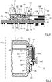
- a radar sensor 10 is shown in different representations.
- the radar sensor 10 can be used, for example, in connection with a driver assistance system of a motor vehicle.
- the radar sensor 10 comprises an openable radar sensor housing 12 in which a ceramic substrate 90 with a radar antenna 14 and a circuit board 16 with components 18 for signal processing and voltage supply are arranged. Furthermore, the radar sensor 10 has a connection plug 20 which leads out of the radar sensor housing 12 and via which the corresponding signal lines and power supply lines can be connected.
- the radar sensor housing 12 is composed of a basic housing part 22 and a radome 24.
- the basic housing part 22 is made of aluminum, for example.
- the radome 24 is made of plastic, for example PBT.
- the radar sensor housing 12 has approximately the shape of a cuboid.
- the basic housing part 22 and the radome 24 each have the shape of an approximately cuboid trough.
- the radome 24 is placed on an edge of a peripheral wall of the basic housing part 22.
- a circumferential wall 28 of the radome 24 engages around the circumferential wall of the base housing part 22.
- the basic housing part 22 has an installation side 26 with an installation opening.
- the ceramic substrate 90 with the radar antenna 14 and the circuit board 16 can be installed through the installation opening.
- the installation side 26 is openably closed with the radome 24.
- the basic housing part 22, the ceramic substrate 90 with the radar antenna 14, the circuit board 16 and the radome 24 are put together parallel to an imaginary assembly axis 30.
- the radome 24 is fixed to the base housing part 22 by means of a total of four essentially identical clamp connections 32.
- the radome 24 is pressed with the clamp connections 32 parallel to the assembly axis 30 against the edge of the peripheral wall of the base housing part 22.
- the clamp connections 32 are located on opposite longitudinal sides of the radar sensor housing 12. Two of the clamp connections 32 are arranged on the same longitudinal side of the radar sensor housing 12.
- Each clamp connection 32 comprises an elastic clamp element 34 on the side of the radome 24 and a latching lug 36 on the side of the base housing part 22.
- the latching lugs 36 are located on the outer circumferential side of the base housing part 22 and rise radially outward with respect to the assembly axis 30. Each of the latching lugs 36 has a wedge-like bevel 38 on its side facing the installation side 26. On the side facing away from the installation side 26, each latching lug 36 has a latching groove 40.
- the clip elements 34 are each elastic spring elements, for example made of spring steel.
- the clamp elements 34 are described below using the clamp element 34 from FIG Figure 4 explained in more detail.
- the clamp element 34 In the area of one of its ends 42, the clamp element 34 has a bend of approximately 90 °. The portion of the clamp element 34 in the region of this bend is embedded in the peripheral wall 28 of the radome 24. The clamp element 34 extends in the region of its end 42 in front of the 90 ° bend with respect to the assembly axis 30 radially inward into a cover-side shoulder 48 of the radome 24. On the end 42 The side facing away from the 90 ° bend, the clamp element 34 extends roughly approximately parallel to the assembly axis 30.
- the clamp element 34 has an S-shaped bend 44 in its central part running approximately parallel to the assembly axis 30.
- the S-shaped bend 44 is located in an area outside the material of the peripheral wall 28.
- the S-shaped bend 44 is in the assembled state approximately at the level of the wedge-like bevel 38 of the corresponding latching lug 36.
- a bending section of the S-shaped bend 44, which faces the peripheral wall 28 of the radome 24, rises towards the peripheral wall of the base housing part 22.
- the clamp element 34 has a latching eye 46 between the S-shaped bend 44 and a free end of the clamp element 34.
- the locking eyelet 46 has the shape of a rectangular window.
- the inner dimensions of the locking lug 46 are somewhat larger than the corresponding outer dimensions of the locking lug 36.
- the locking lug 46 can thus be guided over the locking lug 36 from the outside. In the Figure 4 are indicated by dashed lines for the sake of clarity because of the side boundaries of the locking lug 46 that are actually covered by the locking lug 36.
- the cover-side shoulder 48 forms a rear delimitation of a sealing groove 50, viewed axially to the assembly axis 30 from the radome 24.
- the sealing groove 50 is delimited at the front by a projection 52 of the base housing part 22.
- the projection 52 extends circumferentially on the outer circumferential side of the base housing part 22 with respect to the assembly axis 30.
- the projection 52 is located between the installation side 26 and the latching lug 36, viewed axially to the assembly axis 30.
- the sealing groove 50 is delimited on its radially inner side with respect to the assembly axis 30 by the peripheral wall of the base housing part 22. On the radially outer side, the sealing groove 50 is delimited by the peripheral wall 28 of the radome 24.
- the circumferential wall 28 overlaps the projection 22.
- the circumferential wall 28 lies with its radially inner circumferential side with respect to the assembly axis 30 on the radially outer circumferential side of the projection 22.
- a seal 54 which is circumferentially connected with respect to the assembly axis 30, is arranged sealingly in the radial direction.
- the radome 24 also has a total of four housing-side clamping elements 56 of a clamping device 58 for clamping the ceramic substrate 90 with the radar antenna 14.
- the housing-side clamping elements 56 are in the Figure 2 , in which the radome 24 is shown transparently for the sake of clarity, and the Figure 3 shown.
- the housing-side clamping elements 56 are arranged on the inner top side of the radome 24 facing the base housing part 22.
- the housing-side clamping elements 56 are each approximately cuboid pedestals which, viewed in the direction of the assembly axis 30, extend away from the top side of the radome 24.
- housing-side clamping elements 56 are located in the area of the same circumferential side of the circumferential wall 28, on which the respective clamp elements 34 are also arranged.
- the housing-side clamping elements 56 viewed in the projection, are located approximately between the respective adjacent clamp elements 34.
- the connector 20 leads through a peripheral side of the radar sensor housing 12 between the clamp connections 32 there to the outside. In the interior of the radar sensor housing 12, the connector 20 is electrically and mechanically connected to the circuit board 16. In the usual spatial operational orientation of the radar sensor 10, which in the Figure 2 is shown, the connector 20 is spatially below. In this way it is better protected against the ingress of moisture and water.
- the circuit board 16 is a so-called FR4 circuit card.
- the circuit board 16 is designed as a rectangular flat plate. She's not in here Of further interest, they are fastened in the base housing 22 in such a way that their opposing surfaces each extend perpendicular to the mounting axis 30.
- the components 18 for signal processing and voltage supply are mounted on the surface of the circuit board 16 facing away from the installation side 26 and are electrically connected to corresponding conductor tracks.
- connection device 62 On the surface of the printed circuit board 16 facing the installation side 26, two elongate connection strips 60 of a connection device 62 according to a first exemplary embodiment are arranged.
- the connection device 62 is used for the mechanical and electrical connection of the ceramic substrate 90 to the radar antenna 14.
- the connection strips 60 run as in FIG Figure 2 shown, parallel to one another and each extend between those circumferential sides of the radar sensor housing 12 on which the respective clamp connections 32 are arranged.
- a section of the circuit board 16 with one of the terminal strips 60 is shown in FIG Figure 3 shown in section.
- the connection strips 60 are mechanically connected to the circuit board 16 and electrically to corresponding conductor tracks of the circuit board 16.
- absorber element 64 is flatly attached to the corresponding surface of the printed circuit board 16, for example glued on.
- the absorber element 64 serves to dampen electromagnetic radiation.
- connection strips 60 The structure of the two connection strips 60 is essentially identical. In the following, the structure is based on the terminal strip 60 from FIG Figure 3 explained in more detail.
- the terminal strip 60 has an electrical contact device 66 for making electrical contact with corresponding electrical contact areas 68 on the side of the ceramic substrate 90 with the radar antenna 14. Furthermore, the terminal strip 60 comprises a connection-side clamping element 70 of the clamping device 58. In addition, the terminal strip 60 has an elongated connection base body 72, on which the connection-side clamping element 70 is realized in one piece and in which a plurality of electrical contact elements 74 of the contact device 66 are mounted.
- connection base body 72 is made of electrically insulating material. It extends between the circumferential sides of the radar sensor housing 12.
- the connection-side clamping element 70 is located on a longitudinal side that faces the other connection strip 60 of the connection device 62.
- the connection-side clamping element 70 rises like a pedestal away from the circuit board 16 and over the entire length of the Connection body 72.
- a recess 76 is arranged on the side of the connection-side clamping element 70 facing away from the other connection body 72.
- the recess 76 is open on its side facing away from the circuit board 16. It extends almost over the entire length of the connection base body 72.
- a guide gap 78 is located for the electrical contact elements 78.
- the guide gap 78 extends on the one hand almost over the entire length of the connection base body 72.
- the guide gap 78 connects a rear side of the connection base body 72 facing away from the other connection strip 60 with the recess 76.
- the guide gap 78 opens on the circuit board 16 facing side.
- a pair of holding rods 80 for positioning and mounting the electrical contact elements 74 is arranged in each case.
- the holding rods 80 extend parallel to one another along the connection base body 72.
- the holding rods 80 are made of electrically insulating material.
- a tool holder 82 leads through the upper side of the platform of the connection base body 62 facing away from the printed circuit board 16.
- the tool holder 82 leads into the guide gap 78.
- the tool holder 82 has the shape of an elongated gap which extends beyond the guide gap 78 in the longitudinal direction.
- the tool holder 82 serves to receive and guide an external tool 84 for actuating the contact elements 74.
- the electrical contact device 66 has a multiplicity of electrical contact elements 74 which are arranged next to one another along the connection base body 72 in the guide gap 78.
- the electrical contact elements 74 are not in electrical contact with one another.
- the contact elements 74 of the exemplary embodiment shown are constructed essentially identically.
- Each contact element 74 consists of an elongated elastic electrical conductor, for example a metal spring.
- the contact elements 74 are based on the in Figure 3 contact element 74 shown in more detail.
- the contact element 74 extends through the two openings of the guide gap 78.
- the contact element 74 is mounted between the corresponding holding rods 80 of the two holding rod pairs.
- the contact element 74 is electrically and mechanically connected to a corresponding electrically conductive area of the circuit board 16, for example by means of a soldered connection.
- the contact element 74 is equipped with a contact arm 86 outside the guide gap 78. At its end, the contact arm 86 merges into two fork-shaped contact fingers 88.
- the contact fingers 88 encompass an edge of the ceramic substrate 90 on opposite sides viewed in the direction of the assembly axis 30.
- the contact element 74 also has an actuating section 92.
- the actuating section 92 is located between the contact arm 86 and the end of the contact element 74 fastened to the printed circuit board 16.
- the actuating section 92 is arranged within the guide gap 78 in the region of the tool holder 82.
- the tool 84 can act on the actuating section 92 and thus move the contact arm 86 from the contact position I into an assembly position II.
- the assembly position II of the contact arm 86 is in the Figure 3 indicated by dashed lines.
- the contact fingers 88 are bent away from the circuit board 16 in the direction of the installation side 26.
- the fork which is formed by the contact fingers 88, is ready to receive the ceramic substrate 90 in the assembly position II.
- the ceramic substrate 90 has, for example, the shape of a rectangular plate.
- the ceramic substrate 90 is formed from a multilayer ceramic such as LTCC.
- the plate surface of the ceramic substrate 90 facing the installation side 26 of the base housing part 22 forms an emission side 94 for the radar antenna 14.
- the ceramic substrate 90 has corresponding antenna structures not shown in detail in the figures.
- a part of the electrical contact areas 68, which are the ones shown in FIG Figure 3 upper contact fingers 88 of the respective contact elements 74 are assigned.
- a radar TRX chip 96 is arranged on the rear side of the ceramic substrate 90 and electrically contacted accordingly.
- the radar TRX chip 96 has a transmitter and a receiver for corresponding radar signals.
- the radar TRX chip 96 is arranged in the free area between the ceramic substrate 90 and the circuit board 16.
- the radar TRX chip 96 is located between the terminal strips 60.
- the basic housing part 22, the radome 24, the printed circuit board 16 with the connection strips 60 and the connection plug 22 and the ceramic substrate 90 with the radar antenna 14 are each preassembled.
- the circuit board 16 is with its side carrying the components 18 first in an assembly direction 98, which in the Figure 3 is indicated by an arrow, installed parallel to the assembly axis 30 in the basic housing part 22 and fixed there.
- One of the tools 84 is then inserted into the tool receptacles 82 of the two connection strips 60.
- the contact elements 74 are thus moved into their assembly position II against their elastic restoring force.
- the ceramic substrate 90 with the radar antenna 14 is positioned with the rear side facing away from the emission side 94 first in the assembly direction 98 between the connection strips 60 placed in such a way that the respective longitudinal edges come to lie in the forks of the contact fingers 88 of the corresponding contact elements 74.
- the tools 84 are removed from the tool receptacles 82, as a result of which the contact elements 74 move into their respective contact position I due to their elastic restoring force.
- respective electrical contacts are established between the contact fingers 88 and the respective contact areas 68 of the ceramic substrate 90.
- the ceramic substrate 90 rests in the correct installation position on the connection-side clamping elements 70, supported on opposite sides.
- the radome 24 is plugged onto the base housing part 22 in the assembly direction 98 with the seal 54 interposed.
- the corresponding free ends of the clamp elements 34 are each guided over the wedge-like bevels 38 of the latching lugs 36.
- the clamp elements 34 With a locking tool 100, which is in the Figure 4 is indicated, the clamp elements 34 are pressed at their S-shaped bends 44 to the peripheral wall of the base housing part 22, whereby the respective locking eyes 46 slide over the locking lugs 36.
- the clamp elements 34 snap into place in the corresponding snap-in grooves 40 of the snap-in lugs 36 due to the elastic restoring force of the clamp elements 34.
- the radome 24 is pressed in the direction of the assembly axis 30 against the edge of the base housing part 22.
- the housing-side clamping elements 56 press against the emission side 94 of the ceramic substrate 90.
- the housing-side clamping elements 56 are each located opposite the corresponding connection-side clamping element 70. With the housing-side clamping elements 56, a clamping force is generated in the Figure 3 indicated by an arrow 102, with which the ceramic substrate 90 and thus the radar antenna 14 are clamped between the housing-side clamping elements 56 and the respective connection-side clamping elements 70.
- each contact element 74 has only one contact finger 88. Only the rear contact finger 88 in the assembly direction 98, facing away from the printed circuit board 16, can be moved from a contact position I into an assembled position II and vice versa. The correspondingly other contact finger 88 is fixedly arranged on the side facing the printed circuit board 16
Landscapes
- Engineering & Computer Science (AREA)
- Radar, Positioning & Navigation (AREA)
- Remote Sensing (AREA)
- Physics & Mathematics (AREA)
- Computer Networks & Wireless Communication (AREA)
- General Physics & Mathematics (AREA)
- Computer Security & Cryptography (AREA)
- Electromagnetism (AREA)
- Details Of Aerials (AREA)
- Radar Systems Or Details Thereof (AREA)
- Support Of Aerials (AREA)
Claims (14)
- Capteur radar (10) destiné à un véhicule et comportant au moins un boîtier de capteur radar (12) dans lequel au moins une antenne radar (14) est disposée, le boîtier de capteur radar (12) comportant au moins une partie de boîtier de base (22), pourvue d'un côté de montage (26) au moins destiné à au moins une antenne radar (14), et un radôme (24) qui ferme le côté de montage (26) et qui est traversé pendant le fonctionnement du capteur radar (10) par des signaux émis par l'au moins une antenne radar (14) et/ou des signaux reçus, le boîtier de capteur radar (12) comportant une pluralité d'éléments de serrage élastiques (34) permettant de fixer le radôme (24) à l'au moins une partie de boîtier de base (22), l'un au moins des éléments de serrage (34) étant relié de manière fixe au radôme (24), l'au moins un élément de serrage (34) étant relié au radôme (24) dans la région de l'une de ses extrémités (42), caractérisé en ce que l'au moins un élément de serrage (34) comprend de l'acier à ressort ou est en acier à ressort, en ce que l'au moins un élément de serrage (34) est noyé dans la matière du radôme (24) au niveau de l'une de ses extrémités (42), et en ce que l'au moins un élément de serrage (34) comporte au moins un coude (44) en forme de S de sorte que l'au moins un élément de serrage (34) puisse être plié élastiquement de manière correspondante.
- Capteur radar selon la revendication 1, caractérisé en ce qu'au moins une extrémité (42) de l'au moins un élément de serrage (34) est coulée dans la matière du radôme (24).
- Capteur radar selon l'une des revendications précédentes, caractérisé en ce que l'un au moins des éléments de serrage (34) comporte au moins une portion d'encliquetage (46).
- Capteur radar selon la revendication 3, caractérisé en ce que l'au moins une portion d'encliquetage (46) peut s'encliqueter avec une portion d'encliquetage correspondante côté boîtier (36) de la partie de boîtier de base (22).
- Capteur radar selon l'une des revendications précédentes, caractérisé en ce que l'un au moins des éléments de serrage (34) est disposé de manière à être accessible depuis l'extérieur du boîtier de capteur radar (12).
- Capteur radar selon l'une des revendications précédentes, caractérisé en ce que l'au moins un élément de serrage (34) comporte au moins une portion d'actionnement.
- Capteur radar selon la revendication 6, caractérisé en ce que l'au moins un élément de serrage (34) est actionné dans la portion d'actionnement pour l'ouverture et/ou la fermeture et peut alors être plié élastiquement de manière correspondante.
- Capteur radar selon la revendication 6 ou 7, caractérisé en ce que l'au moins une portion d'actionnement est disposée sur le coude (44) en forme de S de l'au moins un élément de serrage (34).
- Capteur radar selon l'une des revendications précédentes, caractérisé en ce qu'une pression appropriée exercée sur le coude (44) en forme de S permet d'étirer celui-ci et ainsi d'allonger l'au moins un élément de serrage (34) de façon à pouvoir augmenter la distance entre l'extrémité, fixée dans le radôme (24), de l'élément de serrage (34) et une portion d'encliquetage côté boîtier (36) de la partie boîtier de base (22).
- Capteur radar selon l'une des revendications précédentes, caractérisé en ce que la portion de verrouillage (46) peut être poussée ou retournée sur une portion d'encliquetage correspondante côté boîtier (36) de la partie de boîtier de base (22) puis, en raison de la force de rappel élastique de l'au moins un élément de serrage (34), peut entrer dans une liaison d'encliquetage sûre avec celui-ci.
- Capteur radar selon l'une des revendications précédentes, caractérisé en ce que plusieurs éléments de serrage (34) sont disposés de manière répartie circonférentiellement par rapport à une direction d'assemblage (98) du radôme (24) avec la partie de boîtier de base (22) .
- Capteur radar selon l'une des revendications précédentes, caractérisé en ce que le radôme (24) comporte au moins un élément de serrage (56) destiné à la fixation d'au moins une antenne radar (14).
- Capteur radar selon l'une des revendications précédentes, caractérisé en ce que le radôme (24) comprend ou est en une matière synthétique thermoplastique, notamment du téréphtalate de polybutylène (PBT) et/ou du polyamide (PA).
- Capteur radar selon l'une des revendications précédentes, caractérisé en ce que l'au moins un élément de serrage (34) comporte un coude d'environ 90° dans la région de l'une de ses extrémités, la portion de l'élément de serrage (34) étant noyée dans une paroi périphérique (28) du radôme (24) dans la région de ce coude.
Applications Claiming Priority (1)
| Application Number | Priority Date | Filing Date | Title |
|---|---|---|---|
| DE102016123439.7A DE102016123439A1 (de) | 2016-12-05 | 2016-12-05 | Radarsensor für ein Fahrzeug und Verfahren zum Zusammenbau eines Radarsensors |
Publications (3)
| Publication Number | Publication Date |
|---|---|
| EP3330733A2 EP3330733A2 (fr) | 2018-06-06 |
| EP3330733A3 EP3330733A3 (fr) | 2018-09-12 |
| EP3330733B1 true EP3330733B1 (fr) | 2021-07-14 |
Family
ID=60409220
Family Applications (1)
| Application Number | Title | Priority Date | Filing Date |
|---|---|---|---|
| EP17202549.6A Active EP3330733B1 (fr) | 2016-12-05 | 2017-11-20 | Capteur radar pour un véhicule et procédé d'assemblage d'un capteur radar |
Country Status (2)
| Country | Link |
|---|---|
| EP (1) | EP3330733B1 (fr) |
| DE (1) | DE102016123439A1 (fr) |
Families Citing this family (1)
| Publication number | Priority date | Publication date | Assignee | Title |
|---|---|---|---|---|
| EP4582830A1 (fr) * | 2024-01-08 | 2025-07-09 | GM Cruise Holdings LLC | Fermeture de capteur à ressort en fil métallique |
Family Cites Families (3)
| Publication number | Priority date | Publication date | Assignee | Title |
|---|---|---|---|---|
| DE19739298C1 (de) * | 1997-09-08 | 1998-11-12 | Bosch Gmbh Robert | Vorrichtung zur Befestigung eines Entfernungssensors an einem Kraftfahrzeug |
| DE19941931A1 (de) * | 1999-09-03 | 2001-03-29 | Bosch Gmbh Robert | Gehäuse oder Gehäuseteil für einen Abstandsensor |
| DE102005042986A1 (de) | 2005-09-09 | 2007-07-05 | Hella Kgaa Hueck & Co. | Radareinrichtung für ein Kraftfahrzeug und Verfahren zur Herstellung einer Radareinrichtung |
-
2016
- 2016-12-05 DE DE102016123439.7A patent/DE102016123439A1/de not_active Withdrawn
-
2017
- 2017-11-20 EP EP17202549.6A patent/EP3330733B1/fr active Active
Non-Patent Citations (1)
| Title |
|---|
| HOLGERH MEINEL: "2016-08- 13Technical/Barbecuemeeting AutomotiveRadar fromcomforttosafetyandbeyond -thepotentialsandtheobstaclesontheroad tomakeithappen", 13 August 2016 (2016-08-13), XP055684751, Retrieved from the Internet <URL:http://www.mfi-ev.de/2016/2016-08-13_IET-Ulm.pdf> [retrieved on 20200409] * |
Also Published As
| Publication number | Publication date |
|---|---|
| DE102016123439A1 (de) | 2018-06-07 |
| EP3330733A2 (fr) | 2018-06-06 |
| EP3330733A3 (fr) | 2018-09-12 |
Similar Documents
| Publication | Publication Date | Title |
|---|---|---|
| EP3281500B1 (fr) | Appareil de commande | |
| DE102011013449B4 (de) | Baugruppe mit einem Träger, einem SMD-Bauteil und einem Stanzgitterteil | |
| DE102019200912A1 (de) | Radombaugruppe für einen Radarsensor für Kraftfahrzeuge | |
| EP0876743A2 (fr) | Dispositif de commande, notamment pour automobile | |
| DE102015217243A1 (de) | Antennenmodul | |
| WO2012013176A1 (fr) | Support de capteur et module capteur, en particulier à utiliser dans un appareil de commande embarqué dans un véhicule automobile | |
| EP2466552B1 (fr) | Système d'information à bord doté d'une antenne mobile | |
| EP3330737B1 (fr) | Capteur radar pour un véhicule et procédé d'assemblage d'un capteur radar | |
| EP3330733B1 (fr) | Capteur radar pour un véhicule et procédé d'assemblage d'un capteur radar | |
| EP3304641B1 (fr) | Module antenne pour véhicule automobile | |
| EP3728772A1 (fr) | Poignée de portière de véhicule | |
| DE102021207205A1 (de) | Radarsystem zur Umfelderfassung eines Kraftfahrzeugs | |
| EP3331100B1 (fr) | Dispositif de raccordement pour un substrat céramique pourvu d'une antenne radar, capteur radar pour un véhicule et procédé de montage d'un capteur radar | |
| DE102016107898A1 (de) | Laterale Leiterplattenverbindung | |
| DE102009041166B4 (de) | Fahrzeugantenne zum Empfang und/oder zum Senden von Funksignalen | |
| DE102021132798A1 (de) | Radarvorrichtungsanordnung für ein Fahrzeug und Verfahren zur Herstellung einer Radarvorrichtungsanordnung für ein Fahrzeug | |
| DE102005033592A1 (de) | Träger zur Aufnahme eines Antennenverstärkers eines Fahrzeuges | |
| DE102022106579B4 (de) | Heizelement zum Beheizen eines Bauteils eines Kraftfahrzeugs, Steckverbinder zur Verwendung in einem solchen Heizelement und Radom für eine Kraftfahrzeugantenne mit einem solchen Heizelement | |
| DE102013207684A1 (de) | Gehäuse für ein Steuergerät, Steuergerät und Verfahren zur Herstellung eines Steuergeräts | |
| DE102024106589A1 (de) | Abschirmrahmen zur elektrotechnischen Abschirmung von elektrotechnischen Bauteilen einer elektronischen Vorrichtung, welcher wenigstens abschnittsweise in der Höhe elastisch ist | |
| WO2018069119A2 (fr) | Capteur radar présentant un élément de recouvrement | |
| DE202021100738U1 (de) | Fahrzeugantenne sowie System aus Fahrzeugantenne und Trägerblech eines Fahrzeugs | |
| DE102023124172A1 (de) | Radaranordnung für ein Kraftfahrzeug | |
| DE102022206756A1 (de) | Antennenmodul, sowie ein Kraftfahrzeug | |
| EP1471603A2 (fr) | Antenne dans une grille d'aération d'un véhicule |
Legal Events
| Date | Code | Title | Description |
|---|---|---|---|
| PUAI | Public reference made under article 153(3) epc to a published international application that has entered the european phase |
Free format text: ORIGINAL CODE: 0009012 |
|
| STAA | Information on the status of an ep patent application or granted ep patent |
Free format text: STATUS: THE APPLICATION HAS BEEN PUBLISHED |
|
| AK | Designated contracting states |
Kind code of ref document: A2 Designated state(s): AL AT BE BG CH CY CZ DE DK EE ES FI FR GB GR HR HU IE IS IT LI LT LU LV MC MK MT NL NO PL PT RO RS SE SI SK SM TR |
|
| AX | Request for extension of the european patent |
Extension state: BA ME |
|
| PUAL | Search report despatched |
Free format text: ORIGINAL CODE: 0009013 |
|
| AK | Designated contracting states |
Kind code of ref document: A3 Designated state(s): AL AT BE BG CH CY CZ DE DK EE ES FI FR GB GR HR HU IE IS IT LI LT LU LV MC MK MT NL NO PL PT RO RS SE SI SK SM TR |
|
| AX | Request for extension of the european patent |
Extension state: BA ME |
|
| RIC1 | Information provided on ipc code assigned before grant |
Ipc: H01Q 1/42 20060101ALI20180807BHEP Ipc: G01S 13/93 20060101ALI20180807BHEP Ipc: G01S 7/02 20060101AFI20180807BHEP |
|
| STAA | Information on the status of an ep patent application or granted ep patent |
Free format text: STATUS: REQUEST FOR EXAMINATION WAS MADE |
|
| 17P | Request for examination filed |
Effective date: 20190307 |
|
| RBV | Designated contracting states (corrected) |
Designated state(s): AL AT BE BG CH CY CZ DE DK EE ES FI FR GB GR HR HU IE IS IT LI LT LU LV MC MK MT NL NO PL PT RO RS SE SI SK SM TR |
|
| STAA | Information on the status of an ep patent application or granted ep patent |
Free format text: STATUS: EXAMINATION IS IN PROGRESS |
|
| 17Q | First examination report despatched |
Effective date: 20200420 |
|
| REG | Reference to a national code |
Ref country code: DE Ref legal event code: R079 Ref document number: 502017010891 Country of ref document: DE Free format text: PREVIOUS MAIN CLASS: G01S0007020000 Ipc: G01S0013931000 |
|
| GRAP | Despatch of communication of intention to grant a patent |
Free format text: ORIGINAL CODE: EPIDOSNIGR1 |
|
| STAA | Information on the status of an ep patent application or granted ep patent |
Free format text: STATUS: GRANT OF PATENT IS INTENDED |
|
| RIC1 | Information provided on ipc code assigned before grant |
Ipc: H01Q 1/52 20060101ALI20210118BHEP Ipc: H01Q 1/42 20060101ALI20210118BHEP Ipc: H01Q 1/32 20060101ALI20210118BHEP Ipc: G01S 13/931 20200101AFI20210118BHEP Ipc: H01Q 17/00 20060101ALI20210118BHEP Ipc: G01S 7/02 20060101ALI20210118BHEP |
|
| INTG | Intention to grant announced |
Effective date: 20210209 |
|
| GRAS | Grant fee paid |
Free format text: ORIGINAL CODE: EPIDOSNIGR3 |
|
| GRAA | (expected) grant |
Free format text: ORIGINAL CODE: 0009210 |
|
| STAA | Information on the status of an ep patent application or granted ep patent |
Free format text: STATUS: THE PATENT HAS BEEN GRANTED |
|
| AK | Designated contracting states |
Kind code of ref document: B1 Designated state(s): AL AT BE BG CH CY CZ DE DK EE ES FI FR GB GR HR HU IE IS IT LI LT LU LV MC MK MT NL NO PL PT RO RS SE SI SK SM TR |
|
| REG | Reference to a national code |
Ref country code: GB Ref legal event code: FG4D Free format text: NOT ENGLISH |
|
| REG | Reference to a national code |
Ref country code: IE Ref legal event code: FG4D Free format text: LANGUAGE OF EP DOCUMENT: GERMAN |
|
| REG | Reference to a national code |
Ref country code: DE Ref legal event code: R096 Ref document number: 502017010891 Country of ref document: DE |
|
| REG | Reference to a national code |
Ref country code: AT Ref legal event code: REF Ref document number: 1411097 Country of ref document: AT Kind code of ref document: T Effective date: 20210815 |
|
| REG | Reference to a national code |
Ref country code: LT Ref legal event code: MG9D |
|
| REG | Reference to a national code |
Ref country code: NL Ref legal event code: MP Effective date: 20210714 |
|
| PG25 | Lapsed in a contracting state [announced via postgrant information from national office to epo] |
Ref country code: NL Free format text: LAPSE BECAUSE OF FAILURE TO SUBMIT A TRANSLATION OF THE DESCRIPTION OR TO PAY THE FEE WITHIN THE PRESCRIBED TIME-LIMIT Effective date: 20210714 Ref country code: PT Free format text: LAPSE BECAUSE OF FAILURE TO SUBMIT A TRANSLATION OF THE DESCRIPTION OR TO PAY THE FEE WITHIN THE PRESCRIBED TIME-LIMIT Effective date: 20211115 Ref country code: NO Free format text: LAPSE BECAUSE OF FAILURE TO SUBMIT A TRANSLATION OF THE DESCRIPTION OR TO PAY THE FEE WITHIN THE PRESCRIBED TIME-LIMIT Effective date: 20211014 Ref country code: FI Free format text: LAPSE BECAUSE OF FAILURE TO SUBMIT A TRANSLATION OF THE DESCRIPTION OR TO PAY THE FEE WITHIN THE PRESCRIBED TIME-LIMIT Effective date: 20210714 Ref country code: ES Free format text: LAPSE BECAUSE OF FAILURE TO SUBMIT A TRANSLATION OF THE DESCRIPTION OR TO PAY THE FEE WITHIN THE PRESCRIBED TIME-LIMIT Effective date: 20210714 Ref country code: BG Free format text: LAPSE BECAUSE OF FAILURE TO SUBMIT A TRANSLATION OF THE DESCRIPTION OR TO PAY THE FEE WITHIN THE PRESCRIBED TIME-LIMIT Effective date: 20211014 Ref country code: LT Free format text: LAPSE BECAUSE OF FAILURE TO SUBMIT A TRANSLATION OF THE DESCRIPTION OR TO PAY THE FEE WITHIN THE PRESCRIBED TIME-LIMIT Effective date: 20210714 Ref country code: HR Free format text: LAPSE BECAUSE OF FAILURE TO SUBMIT A TRANSLATION OF THE DESCRIPTION OR TO PAY THE FEE WITHIN THE PRESCRIBED TIME-LIMIT Effective date: 20210714 Ref country code: RS Free format text: LAPSE BECAUSE OF FAILURE TO SUBMIT A TRANSLATION OF THE DESCRIPTION OR TO PAY THE FEE WITHIN THE PRESCRIBED TIME-LIMIT Effective date: 20210714 Ref country code: SE Free format text: LAPSE BECAUSE OF FAILURE TO SUBMIT A TRANSLATION OF THE DESCRIPTION OR TO PAY THE FEE WITHIN THE PRESCRIBED TIME-LIMIT Effective date: 20210714 |
|
| PG25 | Lapsed in a contracting state [announced via postgrant information from national office to epo] |
Ref country code: PL Free format text: LAPSE BECAUSE OF FAILURE TO SUBMIT A TRANSLATION OF THE DESCRIPTION OR TO PAY THE FEE WITHIN THE PRESCRIBED TIME-LIMIT Effective date: 20210714 Ref country code: LV Free format text: LAPSE BECAUSE OF FAILURE TO SUBMIT A TRANSLATION OF THE DESCRIPTION OR TO PAY THE FEE WITHIN THE PRESCRIBED TIME-LIMIT Effective date: 20210714 Ref country code: GR Free format text: LAPSE BECAUSE OF FAILURE TO SUBMIT A TRANSLATION OF THE DESCRIPTION OR TO PAY THE FEE WITHIN THE PRESCRIBED TIME-LIMIT Effective date: 20211015 |
|
| REG | Reference to a national code |
Ref country code: DE Ref legal event code: R097 Ref document number: 502017010891 Country of ref document: DE |
|
| PG25 | Lapsed in a contracting state [announced via postgrant information from national office to epo] |
Ref country code: DK Free format text: LAPSE BECAUSE OF FAILURE TO SUBMIT A TRANSLATION OF THE DESCRIPTION OR TO PAY THE FEE WITHIN THE PRESCRIBED TIME-LIMIT Effective date: 20210714 |
|
| PLBE | No opposition filed within time limit |
Free format text: ORIGINAL CODE: 0009261 |
|
| STAA | Information on the status of an ep patent application or granted ep patent |
Free format text: STATUS: NO OPPOSITION FILED WITHIN TIME LIMIT |
|
| PG25 | Lapsed in a contracting state [announced via postgrant information from national office to epo] |
Ref country code: SM Free format text: LAPSE BECAUSE OF FAILURE TO SUBMIT A TRANSLATION OF THE DESCRIPTION OR TO PAY THE FEE WITHIN THE PRESCRIBED TIME-LIMIT Effective date: 20210714 Ref country code: SK Free format text: LAPSE BECAUSE OF FAILURE TO SUBMIT A TRANSLATION OF THE DESCRIPTION OR TO PAY THE FEE WITHIN THE PRESCRIBED TIME-LIMIT Effective date: 20210714 Ref country code: RO Free format text: LAPSE BECAUSE OF FAILURE TO SUBMIT A TRANSLATION OF THE DESCRIPTION OR TO PAY THE FEE WITHIN THE PRESCRIBED TIME-LIMIT Effective date: 20210714 Ref country code: EE Free format text: LAPSE BECAUSE OF FAILURE TO SUBMIT A TRANSLATION OF THE DESCRIPTION OR TO PAY THE FEE WITHIN THE PRESCRIBED TIME-LIMIT Effective date: 20210714 Ref country code: CZ Free format text: LAPSE BECAUSE OF FAILURE TO SUBMIT A TRANSLATION OF THE DESCRIPTION OR TO PAY THE FEE WITHIN THE PRESCRIBED TIME-LIMIT Effective date: 20210714 Ref country code: AL Free format text: LAPSE BECAUSE OF FAILURE TO SUBMIT A TRANSLATION OF THE DESCRIPTION OR TO PAY THE FEE WITHIN THE PRESCRIBED TIME-LIMIT Effective date: 20210714 |
|
| 26N | No opposition filed |
Effective date: 20220419 |
|
| PG25 | Lapsed in a contracting state [announced via postgrant information from national office to epo] |
Ref country code: MC Free format text: LAPSE BECAUSE OF FAILURE TO SUBMIT A TRANSLATION OF THE DESCRIPTION OR TO PAY THE FEE WITHIN THE PRESCRIBED TIME-LIMIT Effective date: 20210714 |
|
| REG | Reference to a national code |
Ref country code: CH Ref legal event code: PL |
|
| GBPC | Gb: european patent ceased through non-payment of renewal fee |
Effective date: 20211120 |
|
| PG25 | Lapsed in a contracting state [announced via postgrant information from national office to epo] |
Ref country code: LU Free format text: LAPSE BECAUSE OF NON-PAYMENT OF DUE FEES Effective date: 20211120 Ref country code: IT Free format text: LAPSE BECAUSE OF FAILURE TO SUBMIT A TRANSLATION OF THE DESCRIPTION OR TO PAY THE FEE WITHIN THE PRESCRIBED TIME-LIMIT Effective date: 20210714 Ref country code: BE Free format text: LAPSE BECAUSE OF NON-PAYMENT OF DUE FEES Effective date: 20211130 |
|
| REG | Reference to a national code |
Ref country code: BE Ref legal event code: MM Effective date: 20211130 |
|
| PG25 | Lapsed in a contracting state [announced via postgrant information from national office to epo] |
Ref country code: LI Free format text: LAPSE BECAUSE OF NON-PAYMENT OF DUE FEES Effective date: 20211130 Ref country code: CH Free format text: LAPSE BECAUSE OF NON-PAYMENT OF DUE FEES Effective date: 20211130 |
|
| PG25 | Lapsed in a contracting state [announced via postgrant information from national office to epo] |
Ref country code: IE Free format text: LAPSE BECAUSE OF NON-PAYMENT OF DUE FEES Effective date: 20211120 Ref country code: GB Free format text: LAPSE BECAUSE OF NON-PAYMENT OF DUE FEES Effective date: 20211120 |
|
| PG25 | Lapsed in a contracting state [announced via postgrant information from national office to epo] |
Ref country code: HU Free format text: LAPSE BECAUSE OF FAILURE TO SUBMIT A TRANSLATION OF THE DESCRIPTION OR TO PAY THE FEE WITHIN THE PRESCRIBED TIME-LIMIT; INVALID AB INITIO Effective date: 20171120 |
|
| PG25 | Lapsed in a contracting state [announced via postgrant information from national office to epo] |
Ref country code: CY Free format text: LAPSE BECAUSE OF FAILURE TO SUBMIT A TRANSLATION OF THE DESCRIPTION OR TO PAY THE FEE WITHIN THE PRESCRIBED TIME-LIMIT Effective date: 20210714 |
|
| P01 | Opt-out of the competence of the unified patent court (upc) registered |
Effective date: 20230528 |
|
| REG | Reference to a national code |
Ref country code: AT Ref legal event code: MM01 Ref document number: 1411097 Country of ref document: AT Kind code of ref document: T Effective date: 20221120 |
|
| PG25 | Lapsed in a contracting state [announced via postgrant information from national office to epo] |
Ref country code: AT Free format text: LAPSE BECAUSE OF NON-PAYMENT OF DUE FEES Effective date: 20221120 |
|
| PG25 | Lapsed in a contracting state [announced via postgrant information from national office to epo] |
Ref country code: MK Free format text: LAPSE BECAUSE OF FAILURE TO SUBMIT A TRANSLATION OF THE DESCRIPTION OR TO PAY THE FEE WITHIN THE PRESCRIBED TIME-LIMIT Effective date: 20210714 |
|
| PG25 | Lapsed in a contracting state [announced via postgrant information from national office to epo] |
Ref country code: MT Free format text: LAPSE BECAUSE OF FAILURE TO SUBMIT A TRANSLATION OF THE DESCRIPTION OR TO PAY THE FEE WITHIN THE PRESCRIBED TIME-LIMIT Effective date: 20210714 |
|
| PG25 | Lapsed in a contracting state [announced via postgrant information from national office to epo] |
Ref country code: TR Free format text: LAPSE BECAUSE OF FAILURE TO SUBMIT A TRANSLATION OF THE DESCRIPTION OR TO PAY THE FEE WITHIN THE PRESCRIBED TIME-LIMIT Effective date: 20210714 |
|
| PGFP | Annual fee paid to national office [announced via postgrant information from national office to epo] |
Ref country code: DE Payment date: 20251117 Year of fee payment: 9 |
|
| PGFP | Annual fee paid to national office [announced via postgrant information from national office to epo] |
Ref country code: FR Payment date: 20251128 Year of fee payment: 9 |