EP3332058B1 - Appareil destiné au traitement du textile, et procédé de fabrication - Google Patents
Appareil destiné au traitement du textile, et procédé de fabrication Download PDFInfo
- Publication number
- EP3332058B1 EP3332058B1 EP16757351.8A EP16757351A EP3332058B1 EP 3332058 B1 EP3332058 B1 EP 3332058B1 EP 16757351 A EP16757351 A EP 16757351A EP 3332058 B1 EP3332058 B1 EP 3332058B1
- Authority
- EP
- European Patent Office
- Prior art keywords
- textile
- tank
- transducer
- distance
- ultrasonic
- Prior art date
- Legal status (The legal status is an assumption and is not a legal conclusion. Google has not performed a legal analysis and makes no representation as to the accuracy of the status listed.)
- Not-in-force
Links
- 239000004753 textile Substances 0.000 title claims description 237
- 238000004519 manufacturing process Methods 0.000 title claims description 11
- 238000012545 processing Methods 0.000 title description 8
- 238000000034 method Methods 0.000 claims description 45
- 230000008878 coupling Effects 0.000 claims description 3
- 238000010168 coupling process Methods 0.000 claims description 3
- 238000005859 coupling reaction Methods 0.000 claims description 3
- 239000012530 fluid Substances 0.000 description 92
- 238000005470 impregnation Methods 0.000 description 30
- 230000008569 process Effects 0.000 description 21
- 239000000126 substance Substances 0.000 description 14
- 238000007872 degassing Methods 0.000 description 11
- 238000009792 diffusion process Methods 0.000 description 11
- 238000002604 ultrasonography Methods 0.000 description 8
- 230000001965 increasing effect Effects 0.000 description 7
- 238000010521 absorption reaction Methods 0.000 description 5
- 238000010276 construction Methods 0.000 description 5
- 238000010586 diagram Methods 0.000 description 5
- 239000000080 wetting agent Substances 0.000 description 5
- 230000000694 effects Effects 0.000 description 4
- 239000004744 fabric Substances 0.000 description 4
- 238000009941 weaving Methods 0.000 description 4
- 230000008901 benefit Effects 0.000 description 3
- 238000004061 bleaching Methods 0.000 description 3
- 238000004140 cleaning Methods 0.000 description 3
- 238000012986 modification Methods 0.000 description 3
- 230000004048 modification Effects 0.000 description 3
- 239000000758 substrate Substances 0.000 description 3
- XLYOFNOQVPJJNP-UHFFFAOYSA-N water Substances O XLYOFNOQVPJJNP-UHFFFAOYSA-N 0.000 description 3
- 238000009736 wetting Methods 0.000 description 3
- 229920002472 Starch Polymers 0.000 description 2
- 230000002411 adverse Effects 0.000 description 2
- 230000015572 biosynthetic process Effects 0.000 description 2
- 230000008859 change Effects 0.000 description 2
- 238000004043 dyeing Methods 0.000 description 2
- 238000005516 engineering process Methods 0.000 description 2
- 230000007613 environmental effect Effects 0.000 description 2
- 230000006872 improvement Effects 0.000 description 2
- 239000007788 liquid Substances 0.000 description 2
- 239000000463 material Substances 0.000 description 2
- 230000008450 motivation Effects 0.000 description 2
- 230000009467 reduction Effects 0.000 description 2
- 229920006395 saturated elastomer Polymers 0.000 description 2
- 235000019698 starch Nutrition 0.000 description 2
- 239000008107 starch Substances 0.000 description 2
- 230000035899 viability Effects 0.000 description 2
- 238000005406 washing Methods 0.000 description 2
- 229920000742 Cotton Polymers 0.000 description 1
- 206010020112 Hirsutism Diseases 0.000 description 1
- 230000006978 adaptation Effects 0.000 description 1
- 238000004364 calculation method Methods 0.000 description 1
- 239000013043 chemical agent Substances 0.000 description 1
- 239000000356 contaminant Substances 0.000 description 1
- 238000010924 continuous production Methods 0.000 description 1
- 230000001276 controlling effect Effects 0.000 description 1
- 238000007796 conventional method Methods 0.000 description 1
- 238000005520 cutting process Methods 0.000 description 1
- 238000013016 damping Methods 0.000 description 1
- 238000013461 design Methods 0.000 description 1
- 238000010981 drying operation Methods 0.000 description 1
- 230000002708 enhancing effect Effects 0.000 description 1
- 238000002474 experimental method Methods 0.000 description 1
- 230000005484 gravity Effects 0.000 description 1
- 231100001261 hazardous Toxicity 0.000 description 1
- 230000002452 interceptive effect Effects 0.000 description 1
- 229920000728 polyester Polymers 0.000 description 1
- 239000011148 porous material Substances 0.000 description 1
- 230000001105 regulatory effect Effects 0.000 description 1
- 238000009999 singeing Methods 0.000 description 1
- 238000004513 sizing Methods 0.000 description 1
- 238000010408 sweeping Methods 0.000 description 1
- 238000012360 testing method Methods 0.000 description 1
- 238000009827 uniform distribution Methods 0.000 description 1
- 238000012800 visualization Methods 0.000 description 1
- 239000002699 waste material Substances 0.000 description 1
- 238000003466 welding Methods 0.000 description 1
- -1 wool Polymers 0.000 description 1
- 210000002268 wool Anatomy 0.000 description 1
- 230000037303 wrinkles Effects 0.000 description 1
Images




Classifications
-
- D—TEXTILES; PAPER
- D06—TREATMENT OF TEXTILES OR THE LIKE; LAUNDERING; FLEXIBLE MATERIALS NOT OTHERWISE PROVIDED FOR
- D06B—TREATING TEXTILE MATERIALS USING LIQUIDS, GASES OR VAPOURS
- D06B13/00—Treatment of textile materials with liquids, gases or vapours with aid of vibration
-
- D—TEXTILES; PAPER
- D06—TREATMENT OF TEXTILES OR THE LIKE; LAUNDERING; FLEXIBLE MATERIALS NOT OTHERWISE PROVIDED FOR
- D06B—TREATING TEXTILE MATERIALS USING LIQUIDS, GASES OR VAPOURS
- D06B2700/00—Treating of textile materials, e.g. bleaching, dyeing, mercerising, impregnating, washing; Fulling of fabrics
- D06B2700/25—Sizing, starching or impregnating warp yarns; Making glazed yarn; Drying sized warp yarns
-
- D—TEXTILES; PAPER
- D06—TREATMENT OF TEXTILES OR THE LIKE; LAUNDERING; FLEXIBLE MATERIALS NOT OTHERWISE PROVIDED FOR
- D06B—TREATING TEXTILE MATERIALS USING LIQUIDS, GASES OR VAPOURS
- D06B2700/00—Treating of textile materials, e.g. bleaching, dyeing, mercerising, impregnating, washing; Fulling of fabrics
- D06B2700/27—Sizing, starching or impregnating fabrics
Definitions
- the subject matter generally relates to an apparatus for textile processing and method manufacturing the apparatus. More specifically, the subject matter relates to an apparatus method of manufacturing the apparatus for impregnation of fluids and chemical into yarn and/or textile and/or fabric.
- yarns used in textile industry have become finer, denser, stronger and with less hairiness. Denser and stronger yarns can now withstand stressed environment of weaving machines. Yarns are applied with the bonding chemical and/or synthesized and/or natural starch to make them strong enough to withstand stresses of high speed weaving preparatory and weaving machine. This has not only resulted in increased speed of production of textile, but also made possible to increase density of the textile. Both, the yarn and the textile thereof have become so dense that intra-yarn space, i.e. space within yarn and inter-yarn i.e. space in between adjacent yarns, have considerably reduced.
- Reduced inter-yarn and Intra-yarn spaces are desirable for a number of reasons, such as fine finish and otherwise improvement in other qualities. At the same time, it also limits absorption capacity of yarn and the textile thereof. Limitation on the absorption capacity of the yarn and the textile is undesirable in course of textile processing. A number of processes often get adversely affected by reduced absorption capability of a yarn or textile. Such processes include wet processing such as singeing, de-sizing, bleaching, mercerizing, dyeing, and washing etc. A number of techniques for increasing the absorption capacity of yarn and the textile have been applied by the industry. However, these techniques are either technology intensive, expensive, less-commercially viable or have problems relating to scaling from laboratory conditions to the industry conditions. Patent documents relating to the Numbers EP 0 969 131 A1 , US 3 688 527 , and WO99/37844 show some solutions which are discussed in more details with reference to subject matter at the end of the specification.
- the subject matter provides an apparatus comprising: a first tank ( 107 ) comprises a first and a second wall, a first transducer ( 107 ), wherein the first transducer ( 107 ) is adapted to transmit ultrasonic waves of a first wavelength into the first tank ( 101 ), and the first tank ( 101 ) is configured to establish a substantially standing ultrasonic wave pattern of the ultrasonic waves inside the first tank ( 101 ), and a disposer ( 109.1 and 109.2 ) adapted to dispose a textile ( 131 ) into the first tank ( 101 ) at a first distance from the first transducer ( 107 ), characterized in that the first distance is determined based on the first wavelength and, wherein the first transducer ( 107 ) is coupled to the first wall ( 103 ) and the second wall ( 105 ) is configured to reflect the ultrasonic waves and the first wall ( 103 ) and the second ( 105 ) are separated from each other to establish the substantially standing wave pattern into the first
- the first transducer ( 107 ) and geometry of the first tank ( 101 ) are configured to expose the textile ( 131 ) to ultrasonic power in a range between 0.2 Watts/cm 2 and 2 Watts/cm 2 .
- the first transducer ( 107 ) and geometry of the first tank ( 101 ) are adapted to transmit at least 8 watts/liter of ultrasonic power into the first tank ( 101 ) .
- the disposer ( 109.1 and 109.2 ) comprises a first plurality of rollers ( 111, 117, 119, 125, 113, 115, 121 and 123 ) and the first plurality of rollers ( 111, 117, 119,125,113, 115,121 and 123 ) are adapted to dispose multiple iterations of the textile ( 131 ) through the first tank ( 101 ) and each iteration of the textile ( 131 ) is separated from adjacent iteration of the textile ( 131 ) by a distance, wherein the distance is determined based on the first wavelength.
- the disposer ( 109.1 and 109.2 ) disposes each of the iterations of the textile ( 131 ) at locations that corresponds to locations of antinodes of the substantially standing ultrasonic wave pattern formed in the first tank ( 101 ).
- a second transducer ( 207 ) wherein the second transducer ( 207 ) is adapted to transmit ultrasonic waves of a second wavelength into a second tank ( 201 ), and the second tank ( 201 ) is configured to establish a substantially standing ultrasonic wave pattern of the ultrasonic waves inside the second tank ( 201 ); and the disposer ( 109.1 and 109.2 ) is configured to dispose the textile ( 131 ) sequentially into the first tank ( 101 ) and the second tank ( 201 ).
- the disposer ( 109.1 and 109.2 ) is configured to dispose the textile ( 131 ) at a second distance from the second transducer ( 207 ) into the second tank ( 201 ), wherein the second distance is determined based on the second wavelength and the disposer ( 109.1 and 109.2 ) is adapted to dispose multiple iterations of the textile ( 131 ) through the second tank ( 201 ) and each iteration of the textile ( 131 ) is separated from adjacent iteration of the textile ( 131 ) by a third distance, wherein the third distance is determined based on the second wavelength and the disposer ( 109.1 and 109.2 ) disposes each of the iterations of the textile ( 131 ) at locations that corresponds to locations of antinodes of the substantially standing ultrasonic wave pattern formed in the second tank ( 201 ).
- the second transducer ( 207 ) and geometry of the second tank ( 201 ) are configured to expose the textile ( 131 ) to ultrasonic power in a range between 0.2 Watts/cm 2 and 2 Watts/cm 2 and are adapted to transmit at least 8 watts/liter of ultrasonic power into the second tank ( 201 ).
- the subject matter provides a method of manufacturing an apparatus comprising: providing a first tank ( 101 ) wherein the first tank ( 101 ) comprises a first wall ( 103 ) and a second wall ( 105 ); configuring the second wall ( 105 ) to reflect the ultrasonic waves and the first wall ( 103 ) and the second ( 105 ) are separated from each other to establish the substantially standing wave pattern into the first tank ( 101 ) resulting in multiple cavitation zones; providing a disposer ( 109.1 and 109.2 ) configured to dispose a textile ( 131 ) at a first distance from the first transducer ( 107 ) and into the first tank ( 101 ), characterized in that the first distance is determined based on a first wavelength; coupling a first transducer ( 107 ) to the first wall ( 103 ) of the first tank ( 101 ), wherein the first transducer ( 107 ) is configure to transmit ultrasonic waves of the first wavelength into the first tank ( 101 ); and configuring the
- the method includes configuring the first transducer ( 107 ) and geometry of the first tank ( 101 ) to: expose the textile ( 131 ) to ultrasonic power in a range between 0.2 Watts/cm 2 and 2 Watts/cm 2 ; and transmit at least 8 watts/liter of ultrasonic power into the first tank ( 101 ) .
- providing the disposer ( 109.1 and 109.2 ) includes providing a first plurality of rollers ( 111, 117, 119, 125, 113, 115,121 and 123 ) and adapting the first plurality of rollers ( 111, 117, 119, 125, 113, 115,121 and 123 ) to dispose multiple iterations of the textile ( 131 ) through the first tank ( 101 ), wherein each iteration of the textile ( 131 ) is separated from adjacent iteration of the textile ( 131 ) by a distance determined based on the first wavelength.
- providing the disposer includes adapting the disposer ( 109.1 and 109.2 ) to dispose each of the iterations of the textile ( 131 ) at a location that corresponds to location of an antinode of the substantially standing ultrasonic wave pattern formed in the first tank ( 101 ).
- the subject matter provides a solution for impregnation of yarn/textile using ultrasonic technology.
- the subject matter focuses on geometry of equipment and distance between transducer and textile, location of transducers and providing effective environment to cause impregnation of a fluid into the textile.
- the subject matter provides the geometry of equipment to establish substantially standing ultrasonic waves and positioning of textile at a predetermined location based on a number of parameters such as, ultrasonic power per square centimeter on textile, ultrasonic power per liter of fluid and contact time of textile and fluid, effective use of reflected ultrasonic waves that form standing wave pattern.
- the subject matter provides solution for handling variety of textiles for example, cotton, wool, polyester and other yarns have different characteristics of absorbency and requirement for impregnation by providing electronically controlled disposing of textile in a tank and electronically controlling positioning of textile and characteristics of ultrasonic waves, such as, sweep characteristics.
- FIG. 1 shows an apparatus 100 according to one embodiment of the subject matter.
- FIG. 1 shows a first tank 101, a first wall 103, a second wall 105, a first transducer 107, blocks 109.1 and 109.2 (disposer), a first plurality of rollers 111, 117, 119,125, 115, 113, 121 and 123, an inlet 127, an outlet 129 and a textile 131 (also referred to interchangeably as yarn or fabric).
- the apparatus 100 is configured to impregnate the textile 131 with a fluid that is filled in the first tank 101.
- the apparatus 100 is employed for impregnating textile 131 with water and other chemicals, for example, de-size chemicals, bleaching chemicals etc.
- the textile 131 is impregnated prior to wet processing of the textile 131. It shall become clear to a person in the art, after reading this specification that the apparatus illustrated in FIG. 1 and other FIGURES described herein, may be equally applicable and configurable to impregnate yarn and textile and that there may be additional equipment and hardware not shown in the FIG. 1 and other FIGURES described herein, but may be required for the operations of the apparatus.
- Additional equipment and hardware may include, but not limited to, recirculation pumps, compressors, additional impregnation sections, chemical dosing pumps for maintaining the chemical concentration in the first tank 101, motor drives for nip rolls and other rollers, level sensors, level controllers, pneumatic valves, programmable logic controllers (PLC), human machine interfaces (HMI) for control and visualization, ultrasonic generators and power supplies.
- recirculation pumps compressors, additional impregnation sections
- chemical dosing pumps for maintaining the chemical concentration in the first tank 101
- motor drives for nip rolls and other rollers
- level sensors level controllers
- PLC programmable logic controllers
- HMI human machine interfaces
- Operation of the apparatus 100 may be understood as follows. As shown in FIG. 1 .
- the textile 131 may be configured to be pulled through the disposer 109.1 and 109.2.
- the disposer has the first plurality of rollers 111, 117, 119, 125, 113, 115, 121 and 123. It shall be clear to the person, after reading this specification, that a motor (not shown) may roll the textile 131 and cause the textile 131 to pass through the disposer 109.1 and 109.2 as shown in the FIG. 1 .
- Combination of rollers 111, 115, and 113 of the first plurality of rollers causes the textile 131 to make first iteration through the first tank 101 and thereby exposing the textile 131 to the fluid filled in the first tank 101 and the ultrasonic waves which the first transducer 107 introduces into the first tank 101.
- combinations of rollers 113 and 117; 117, 119 and 121; and 121, 123 and 125 of the first plurality of rollers respectively cause the textile 131 to make second, third and fourth iteration through the first tank 101, working in tandem with each other.
- the each of the first plurality of rollers 111, 117, 119, 125, 113, 115,121 and 123 depends on the number of iteration that the textile 131 needs make through the first tank 101.
- the disposer is configured to suspend and/or dispose the textile 131 into the first tank 101 and keep the textile moving continuously. Further technical operation of the apparatus shall become clearer from the subsequent discussion.
- the construction of the apparatus 100 may be understood as follows.
- the apparatus 100 has the first tank 101.
- the first tank 101 comprises the first wall 103 and the second wall 105.
- the first wall 103 is provided with the first transducer 107.
- the first transducer 107 is coupled to the first wall 103 and the first transducer 107 is configured to generate ultrasonic waves of a first wavelength ( ⁇ 1 ).
- Material of the first wall 103 and second wall 105 is selected such that they optimally reflect the ultrasonic waves in the first tank 101.
- Distance between the first wall 103 and the second wall 105 is such that the ultrasonic waves transmitted in the first tank 101 establish a substantially standing wave pattern. In FIG. 1 the distance show is 3 times the first wavelength ( ⁇ 1 ).
- the substantially standing ultrasonic waves are referred to as standing waves, or standing ultrasonic waves.
- the first wavelength ( ⁇ 1 ) may be determined.
- the height of the first tank 101 and the distance between the first wall 103 and the second wall 105 may be determined based on and length of textile (131) that travels through the first tank (101) and the number of iterations that the textile 131 makes through the fluid of the first tank 101.
- the length of the textile 131 in first tank 101 is determined based on textile web speed in continuous production operation and a duration of time for which the textile 131 and the ultrasonically active fluid is desired to remain in contact (also referred to as "contact time").
- the disposer 109.1, 109.2 disposes the textile 131 in the first tank 101 in such a manner that ultrasonic waves produced by the first transducer 107 travels in substantially perpendicular direction of the textile 131.
- the textile 131 is disposed substantially longitudinally across the first tank 101. It shall become clear, after reading this specification that the distance between the first wall 103 and the second wall 105 of the first tank 101 is substantially close to a number which is equal to the first wavelength ( ⁇ 1 ) multiplied by an integer (n).
- the integer (n) may depend on the number of iterations of the textile 131 through the first tank 101. For example, in FIG.
- each of the iterations of textile 131 is spaced from each other at least by a first distance which is substantially close to ⁇ 1 /2 which is half of the first wavelength ( ⁇ 1 ).
- the geometry of the first tank 101 is determined based on the first wavelength ( ⁇ 1 ) and power of ultrasonic waves that need to be transmitted into the first tank 101. For example if the power needed to be transmitted is 8 Watts/liter, then based on the first wavelength ( ⁇ 1 ) distance between the first wall 103 and the second wall 105 may be determined. Based on the distance between the first wall 103 and the second wall 105, the first wavelength ( ⁇ 1 ) and characteristics of the first transducer 107 height of the first wall 103, and second wall 105 may be determined so that 8 Watts/liter of ultrasonic power is transmitted into the first tank 101.
- the vertical height of the first and second walls 103, 105 and first transducer 107 is selected based on the time for which the textile 131 is desired to be exposed to the ultrasonic waves, the fluid, the first wavelength ( ⁇ 1 ), power/liter of ultrasonic waves transmitted by the first transducer 107 into the first tank 101 and power/cm 2 of the ultrasonic waves that the textile 131 is desired to be exposed to.
- quality and type of textile 131 may be used to determine the geometry of the first tank 101.
- the geometry of the first tank 101 may also be decided by the web width of the textile 131.
- the first tank 101 is provided with the inlet 127 and the outlet 129 for allowing entry and exit of the fluid respectively.
- the first transducer 107 may be of 25 KHz, 4000 Watt for a surface area of one iteration of textile 131 of 7200 cm square exposed to the first transducer 107.
- the effective Watts/cm 2 is slightly higher than 0.5 Watts/cm 2 .
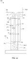
- FIG. 1a shows another embodiment of an apparatus 700 according to an embodiment of the subject matter.
- the embodiment shows a first tank 701, a first wall 703, a second wall 705, a first transducer 707, blocks 709.1 and 709.2, a first plurality of rollers 711, 713, 721 and 725, an inlet 727, an outlet 729 and a textile 731.
- the discussion of the embodiment 100 of FIG. 1 applies mutatis mutandis for the embodiment 700 shown in FIG. 1a the only difference in the two embodiments is configuration of the disposer 109.1, 109.2 and the blocks 709.1 and 709.2 respectively. From the FIG.
- the textile 731 is disposed in the first tank 701 and make multiple iterations through the first tank 701. Each of the iteration is separated from adjacent iteration by a third distant and the third distant is determined by wavelength of ultrasonic waves produced by the first transducer 707. It shall become clear to a person, after reading this specification that the disposer may have a configuration different than what is shown in FIG. 1 and FIG. 1a , without departing from spirit of the subject matter. Further it should also be understood from Fig. 1a that in some embodiments some iteration of textile (e.g.
- the iteration supported by rollers 717 and 713 may be disposed in the first tank 701 based on the first wavelength so that most of the iterations of the textile are dispose at distance from the first transducer 707 which is integer multiple of the half of the first wavelength.
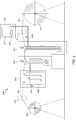
- FIG. 2 shows the subject matter according to another embodiment, in that, the apparatus comprise the block 100 of FIG. 1 coupled to a block 200. So far as construction and operation of the block 200 and corresponding reference numerals of block 200 are concerned, discussion of FIG. 1 applies mutatis mutandis.
- the block 200 is substantially similar to that of the block 100 except that the block 200 comprises second transducer(s) 207.
- the second transducers 207 may generate ultrasonic waves of a second wavelength ( ⁇ 2 ).
- the second wavelength ( ⁇ 2 ) may be same or is different from the first wavelength ( ⁇ 1 ).
- the inlet 127 is coupled to the outlet 229 of block 200.
- the textile 131 is sequentially disposed into the first tank 101 and the second tank 201.
- FIG. 3 shows another embodiment 300 of the subject matter.
- the block 100 of FIG. 1 is provided with block 200 as described with reference to FIG. 2 and is further provided with an un-winder 301, nip rolls 303 and 311, a block 305, an outlet 325 of a fluid tank 315, a fluid source 307, a degassing tank 317, a steam inlet 327, a valve 309 and a winder 313.
- the operation and construction of the embodiment 300 may be understood as follows.
- the textile 131 is unwound from the un-winder 301 and is subjected to a 3-stage impregnation process through the blocks 305, 100 and 200. Once the textile 131 has been through the blocks 305, 100 and 200 the textile 131 is transported and wound on the winder 313.
- the textile 131 is pulled by the nip rolls 303 and 311.
- the nip rolls 303 and 311 may be coupled to prime movers such as electric motors (not shown).
- the block 305 comprises the fluid tank 315 and the outlet 325.
- the fluid tank 315 receives fluid from the block 100 that is the outlet 129 may be coupled to an input of the fluid tank 315 .
- the textile 131 gets wet. Wetting of textile may help in adapting the textile 131 to expose it to ultrasonic cavitation and forming nuclei at its surface. For example, subjecting the textile 305 may remove large bubbles that form on the surface of textile 131 when the textile is introduced into the fluid however, does not remove finer bubbles in the inter-yarn space that get forwarded to block 100 along with the textile 131. Further wetting may help in removing undesired hard size.
- a plurality of rollers may be disposed in block 305 to facilitate the textile 131 to pass through the fluid in a plurality of iterations.
- block 307 may be provided to supply fluid.
- the block 307 may comprise the degassing tank 317 and the steam inlet 327.
- Providing the degassing tank 317 and the steam inlet 327 is improves impregnation using ultrasonic becomes by removing dissolved gasses from fluid. Reduced dissolved gasses in fluid cuts down damping effect and improves cavitation due to ultrasonic waves.
- the degassing tank 317 is provided with the steam inlet 327 that releases stream of steam bubbles into the fluid causing degassing and adjusting temperature of the fluid.
- degassing of the fluid may also be achieved by degassing with ultrasonic.
- the volume of the degassing tank 317 and the required fluid is provided based on weight of the textile 131 that needs to be impregnated.
- the volume of the fluid is based on processing need of the textile 131 in Kg/Hour and fluid required to do that process in Liters/Kg of the textile 131.
- the de-size chemical and wetting agent are dozed in the block 200.
- the wetting agents may be dozed in block 200 or block 100 or a combination of 100, 200 and 305 according to the impregnation requirements.
- the degassing tank 317 is coupled to the inlet 227 of the block 200 through the valve 309 which controls the rate of flow of the fluid to the block 200 and also to the subsequent blocks namely 100 and 305.
- fluid in each block 100, 305 and 200 flow below fluid level surface of tank of each block 100, 200 and 305 in each of the blocks 100, 200 and 305 to reduce possibility of trapping air by fluid while flowing and excess fluid flows from one block to another starting from block 200 to block 100 and then to block 305 and ultimately the fluid exits from the outlet 325.
- the block 100, 200 and 305 may be provided with one or more circulation pumps (not shown).
- the circulation pump may pump the fluid from the bottom of tank and feed it back into the tank.
- the subject matter provides that the circulation pump of respective block 100, 200 and 305 is configured such that the pump discharges the fluid on top of respective tanks 315, 101, and 201 however, level at which the pump discharges the fluid is below the fluid level in respective tanks.
- circulating fluid from bottom to top in each block 100, 200 and 305 may provide uniform concentration of fluid.
- the fluid discharge at the top of section is below fluid level surface at low flow rate to avoid possibility of airtrapping in fluid while circulating the fluid within the first tank 101 or the second tank 201.
- one or more pumps may be provided for circulating fluid in a given tank.
- the ultrasonic power may be effectively utilized by positioning the transducers 107 and 207 such that the ultrasonic waves emitted by the transducer 107 and 207 are in the natural direction of the flow of the fluid which is from block 200 to block 100 and so on, as shown the FIG. 3 .
- the ultrasonic streaming in same direction as the flow of fluid helps in localized concentration equalization within the fluid.
- the apparatus 300 is monitored and controlled using programmable logic controllers (PLC) at every stage to ensure consistency and reliability of processes. If there is a change in textile type and process conditions, the logic controllers are suitably programmed to adapt to the changes thereof.
- PLC programmable logic controllers
- Use of PLC provides enhanced consistency and reliability of process. Further, PLC provides flexibility to adapt for changes in textile type and compensate for the changes in process conditions.
- a Piezo electric sensor may be used to control the ultrasonic transducer power for automatic adaptation of process needs and textile type.
- an ultrasonic generator operates with a sweep frequency in a band near to main operating frequency of ultrasonic transducer.
- a wavelength of ultrasonic wave inside a fluid may not remain constant due to changes in the industrial operating and environmental factors such as change in temperature or concentration of the fluid.
- maintaining the distance of the textile 131 substantially precisely at a distance of integral multiples of ⁇ 1 /2 in block 100 may not be practically feasible due to the elastic structure of the textile 131, movement of the textile 131 around the combinations of rollers 113 and 117; 117, 119 and 121; and 121, 123 and 125 may give rise to changes in the distance of the textile 131 from the first wall 103.
- the subject matter overcomes these practical issues by providing ultrasonic generators and the ultrasonic transducers 107, 207 that are capable of altering the frequency/wavelength of their operation. That is to say, the adapting the apparatus of the subject matter to operate on a sweep frequency. Consequently the wavelength of operation in a fast and continuous manner to accommodate for the changes in the distance of the textile 131 from the transducers 107,207 and other operating conditions e.g. temperature and concentration. In one embodiment, the frequency and wavelength are changed to accommodate a shift in the position of the textile 131. By providing a continuously sweeping frequency assist in improving reliability and repeatability of the impregnation process in changing operating conditions.
- the sweep frequency of the ultrasonic generators may be adapted to changes in the environmental conditions such as slight web movement, temperature changes and fluid concentration changes.
- disposing the textile 131 according to the subject matter into the first tank 101 or the second tank 201 also accounts for the attenuation of the ultrasonic waves.
- the nature (flexibility and transparency for ultrasonic waves and textile having thickness much less than wavelength) of the textile 131 is such that it leaves the ultrasonic waves substantially unaltered and causes negligible amount of attenuation.
- This feature enables that a single transducer may be used for exposing the textile 131 to ultrasonic waves/filed for multiple time by deploying multiple iterations of the textile 131 through the first tank 101. This feature increases the contact time of the textile 131, fluid and ultrasonic filed.
- rollers result in increased in size of the set up and therefore, also require increase size, power and number of ultrasonic transducers which is not practical for industry because power requirement of the transducers is prohibitively high for the industry. Furthermore using smaller size of rollers is not desirable as smaller size of roller cause wrinkle issue with the textile.
- the size of the rollers is about 100 mm to 200 mm which may generally an industry standard. The subject matter addresses the above challenge by effectively introducing the rollers, while disposing the textile 131 at a distance from the source of the ultrasonic as taught with reference to FIG. 1 , FIG. 2 and FIG. 3 .
- the power of ultrasonic is effectively utilized because, the textile 131 is disposed in accordance with the wavelength of the ultrasonic and size of the tank in which the ultrasonic is radiated on the textile 131 is selected based on the wavelength.
- the power of the ultrasonic is distributed substantially uniformly, without much attenuation in the first tank 101 because, the size of the first tank 101 is in the order of the multiples of wavelength of the ultrasonic, therefore, standing wave formation and substantially uniform cavitation occurs in the first tank 101.
- the wetting agent and other chemicals may added at block 200.
- amount of wetting agent and other chemical required for processing textile according to the subject matter may be considerably lower as compared with conventional methods.
- the subject matter may demonstrate reduction in the quantity of wetting agent up to one fifth or up to one fourth of the normal usage in industry.
- Water flow rate to block 200 from degas tank may be regulated with valve 309 based on textile Kg/Hour rate.
- Diffusion is phenomenon, which occurs in textile, without regards to the volume of the fluid.
- ultrasonic power required is higher for higher volume of the fluid is used. Therefore, it is desirable to keep the volume of the fluid at its lowest as smaller volume while leave the diffusion unaffected it assist in conserving power of the ultrasonic transducer. While it is desirable that the volume of the fluid is kept at its minimum, however reduction in volume of the fluid must accompany with increase in the velocity of fluid through the tank in order to keep up effective concentration of fluids. However, increased velocity of fluid through the tank diminishes ultrasonic effect. That is beyond certain point further reducing the volume of the fluid in the tanks become counterproductive because the fluid velocity required starts disrupting the effect of ultrasonic on the textile. Providing the size of the tank in the order of the wavelength and disposing the textile according to the subject matter addresses this conflict between the velocity of fluid, volume of fluid and ultrasonic power and provides an effective solution for impregnation of textile.
- FIG. 4 shows schematic diagram for the ease of understanding of the subject matter. Shown in FIG. 4 are: an ultrasonic transducer 503 that produces ultrasonic waves of wavelength ⁇ , a proximal wall 505, distant wall 501, textile iterations 502, 507, 509, 511 and/or 519.
- the transducer 503 is coupled to the proximal wall 505.
- the distance between transducer 503 and the proximal wall 505 is negligible.
- the standing wave pattern and the dimensions/configuration of the apparatus is determined by the distance between the transducer 503, the proximal wall 505 and the distant wall 501.
- the proximal wall 505 is selected of a material that can pass the ultrasonic waves from one side with least attenuation in one direction, whereas reflects the waves substantially totally from other side.
- the proximal wall 505 is an ultrasonic source.
- the standing ultrasonic wave pattern is formed between the proximal wall 505 and distal wall 501.
- Standing wave pattern of ultrasonic generates highest cavitation phenomenon at positions, which are at a distance that is integer multiples of ⁇ /2.
- the distance is determined from the proximal wall 505 or the transducer 503.
- the textiles 502, 507, 509, 511 and/or 519 are separated at a distance in multiples of ⁇ /2 from the transducer 503 as shown in the FIG. 4 .
- the distance between the distant wall 501 and proximal wall 505 may be an integer multiple of the wavelength ⁇ .
- the standing wave pattern creates pressure antinodes at (n X ⁇ /2) and pressure node at (2n+1) ⁇ /4. (Where "n” is an integer).
- This way effective ultrasonic pressure at multiple of ⁇ /2 distances will be almost twice, giving rise to cavitations at regions where textile 502, 507, 509, 511 and/or 519 are disposed.
- ultrasonic pressure difference between pressure antinodes at n ⁇ /2 and pressure nodes at (2n+1) ⁇ /4 helps in uniform distribution of fluid concentration with low velocity micro-flow. Geometrical placement of yarn/fabric/textile is guided so that yarn/fabric/textile remains at place of pressure antinodes which are higher cavitation zones.
- the textile 502, 507, 509, 511 and/or 519 impregnated according to the subject matter provides a number of advantages as discussed earlier.
- the above processes are generally governed by physical processes of fluid exchange between textile by convection and diffusion.
- impregnation of fluid in-between yarn (inter-yarn) portion of textile results from convection, which is comparatively faster physical process than diffusion.
- impregnation of fluid within yarn (intra-yarn) which is major part of total impregnation and it results from diffusion. That is, the main process of impregnation involves diffusion.
- the diffusion depends on yarn surface characteristics and is generally difficult to enhance.
- the subject matter provides solution to this problem by effectively employing the ultrasonic for enhancing both the physical processes of impregnation to textile, convection and diffusion.
- the subject matter provides a number of flexibilities in processing the textile, for example, the amount of absorption of fluid by the textile may be improved without making extensive changes in the system.
- existing solutions require repeating the wetting processes or running the textile multiple times through fluid.
- Current industrial processes are based on method of concentration exchange between the textile and fluid by moving textile multiple times through the fluid.
- the subject matter provides improvement over these processes.
- the existing methods not only fail to provide desired results but also, hamper production, waste fluids, water wastage is high, power consuming, result in higher chemical usage and environmentally hazardous effluents, resource intensive in terms of size of equipment, cost of running, infrastructure etc, higher temperatures of process, and higher textile contact time with fluid for increasing impregnation. Therefore, these methods are undesirable.
- the subject matter further addresses challenges related to developing an industry scale application of ultrasonic based impregnation of textile.
- Industry application of ultrasonic based textile impregnation is challenging because the ultrasonic pressure wave may cause the textile to move.
- Such characteristic of textile calls for power requirement of ultrasonic in terms of Watts/cm 2 instead of normal standard cleaning calculation in Watts/liter.
- industrial web width and roller size is generally higher than 1800 mm and 100 mm respectively. Therefore, for industry applications up-scaling of ultrasound impregnation apparatus results in ultrasonic power requirements prohibitively higher than what is practical.
- the subject matter solves this problem by optimally adjusting and selecting geometry of the tank and the transducers, and iterations of textile into the tank, to exploit cavitations caused by the ultrasonic waves such that ultrasonic power required in an unit area of textile (Watts /cm 2 ) for a given contact time is achieved without compromising on the ultrasonic power required in the tank for a give unit of fluid (Watts/liter).
- the subject matter provide degassing and flow control and direction of flow of fluid which improves effectiveness of ultrasonic based impregnation, as non-degassed fluid generally adversely affect the ultrasonic impregnation.
- the subject matter also provides flexibility of construction of the apparatus because, the ultrasonic waves operation on the textile is substantially independent of gravity, the tank and transducers may be deployed horizontally or vertically or at any suitable angle, with appropriate adjustments without effecting efficiency of the apparatus.
- FIG. 5 shows a method 600 according to an embodiment of the subject matter.
- the method provides a first tank and at block 603 a first transducer is coupled to the first tank.
- the first transducer is configure to transmit ultrasonic waves of a first wavelength into the first tank and the first tank is configured to form a substantially standing ultrasound wave pattern into the first tank.
- the method includes providing a disposer.
- the dispose is configured to dispose a textile at a first distance from the first transducer and into the first tank. The first distance is determined based on the first wavelength.
- the block 605 further includes block 615, and block 625.
- the disposer includes providing a first plurality of rollers and adapting the first plurality of rollers to dispose multiple iterations of the textile through the first tank, wherein each of the iterations of the textile is separated from adjacent iteration of the textile by a distance determined based on the first wavelength.
- the method provides adapting the disposer to dispose each of the iterations of the textile at a location that corresponds to location of an anti-node of the substantially standing ultrasonic wave pattern formed in the first tank.
- the method further includes configuring the first transducer and geometry of the first tank to cause the textile to ultrasonic power in a range between 0.2 Watts/cm2 and 2 Watts/cm2 and transmit at least 8 watts/liter of ultrasonic power into the first tank.
- the method provides configuring the apparatus to operate on a sweep frequency of ultrasonic waves, the sweep frequency is a band of frequencies around a first frequency, wherein the first frequency corresponds to the first wavelength and the disposer is configured to dispose the first textile at the first distance, the first distance is determined based on the first frequency.
- Patent documents relating to the numbers EP 0 969 131 A1 , US 3 688 527 , and WO99/37844 show some solutions. While these documents attempt to reach at some solution that employ ultrasound in cleaning, these documents suffer from a number of limitations, including those discussed previously relating to laboratory scale experiments and non-viability on commercial scale and other technical challenges.
- EP 0 969 131 A1 discloses a device for treating textile, comprising a tank (2) for holding treatment liquid (3), conveyor means (4) for conveying a textile substrate (7) which is to be treated through the tank (2), a transducer (8) for generating ultrasonic vibrations in the treatment liquid (3), an interference element (19) placed opposite the transducer for together delimiting a vibration cavity (13), wherein the transducer (8) together with the interference element (19) is designed to generate an interference pattern in the vibration cavity (13) of ultrasonic vibrations amplifying each other, in which a concentration area (11) of intensified vibration energy occurs at a distance from the transducer (8) and the interference element (19), in which the conveyor means (4) are designed to guide the textile substrate (7) through the concentration area (11), and in which energy of the ultrasonic vibrations is destined to dissipate by means of cavitation in the concentration area (11) at the location of the textile substrate (7).
- EP 0 969 131 A1 attempts to employ ultrasonic wave solution in textile industry, it fails to recognizes challenges relating to obtaining a stable concentration area (11), in which energy of the ultrasonic vibrations is destined to dissipate by means of cavitation. Because the concentration area (11) is highly susceptible to physical parameters of the medium. The position of concentration area (11) changes with temperature pressure etc. In fact in some case, concentration area (11) may not be in a substantially vertically aligned, as envisioned by the EP 0 969 131 A1 , due to changes in temperature of the medium at different heights in a given tank.
- EP 0 969 131 A1 provides a complex solution which employs a number of transducers each focusing in different direction, interfering elements and ultrasound unit 9.
- the present subject matter solves at least both the problems associated with the EP 0 969 131 A1 .
- the present subject matter configures the walls of the tank itself eliminating need of a separate ultrasonic unit 9 altogether.
- the apparatus of the present subject matter operates on a sweep frequency.
- the ultrasound unit 9 of EP 0 969 131 A1 requires multiple combinations of transducers and interference elements (the interference element being transducers themselves) and some focusing arrangement to guide the ultrasonic waves in specific direction, into the tank.
- This arrangement of the EP 0 969 131 A1 not only makes the solution of the EP 0 969 131 A1 practically not workable but also makes it more complex. This is because, when a number of transducers each of them focusing in different directions (see, Fig 1 items 8 of EP 0 969 131 A1 ) pass a number of ultrasonic waves through a single continuous medium, the medium does not see these waves as separate waves coming from different sources/direction. Instead the medium sees some convolution of waves.
- FIG. 1a shows an exaggerated embodiment of the present subject matter, in which the textile is disposed in the tank in which at least one iteration is obliquely or diagonally disposed.
- the apparatus may be configured to operate based on the sweep frequency and dispose textile using the rollers accordingly in number of ways. It shall become clear to a person in the art that the textile may be kept in the cavitation zone by a number of ways, which may include combination of adjustment of rollers and adjustment of frequency etc.
- the apparatus may be configured to solve these problems by disposing the textile in a diagonal/oblique manner (shown in FIG. 1a ) so that the textile traverses maximum part though the caviation zone, as is understood that the slope of the diagonal/obliqueness may be determined based on the sweep frequency.
- the apparatus may be configured to solve these problems by adjusting the roller positions (see, paragraph [0046]). In a further another embodiment the apparatus may be configured to solve these problems by adjusting the textile positions (see, paragraph [0046]). In another embodiment the apparatus may be configured to solve these problems by (see paragraph [0033]) adaptively selecting or altering the transducer frequency, and adjusting the textile positions (see, paragraph [0046]).
- the EP 0 969 131 A1 also fails commercial viability test because of only single iteration of textile may be treated at a given time, whereas the subject matter efficiently utilizes energy and time by enabling disposing of textile in multiple iterations without compromising on the advantages of cavitation zones and therefore the subject matter provides a better and cheaper solution.
- US 3 688 527 discloses, a method and apparatus for cleaning mechanically bonded contaminants from a resilient web in a fluid medium.
- US 3 688 527 diverts from the present subject matter, more often than not the textile is rather delicate and not resilient. It is therefore US 3 688 527 shows a sonotrode type of transducer, generally used for cutting and welding operations.
- Employing US 3 688 527 in textile industry would only result in damaged textile. It is therefore despite of US 3 688 527 being in public since 1972, industrial scale solution employing ultrasounds to process textile are not available in the market.
- WO99/37844 is another document, the document does not discuss either the problems addressed by the present subject matter or provides a solution thereof. Furthermore, for treating different sides of the textile, the WO99/37844 requires two transducers one for each side of the textile. It does not provide any indication or motivation for disposing the textile based on either sweep frequency or corresponding wavelength.
- the present subject matter provides an apparatus comprising: a first transducer ( 107 ), characterized in that wherein the first transducer ( 107 ) is adapted to transmit ultrasonic waves of a first wavelength into a first tank ( 101 ), and characterized in that the first tank ( 101 ) is configured to establish a substantially standing ultrasonic wave pattern of the ultrasonic waves inside the first tank ( 101 ); and a disposer ( 109.1 and 109.2 ) adapted to dispose a textile ( 131 ) into the first tank ( 101 ) at a first distance from the first transducer ( 107 ), wherein the first distance is determined based on the first wavelength and, wherein the first tank ( 101 ) comprises a first wall ( 103 ) and a second wall ( 105 ), the first transducer ( 107 ) is coupled to the first wall ( 103 ) and the second wall ( 105 ) is configured to reflect the ultrasonic waves and the first wall ( 103 ) and the second ( 105 ) are separated
- the first transducer ( 107 ) and geometry of the first tank ( 101 ) are configured to expose the textile ( 131 ) to ultrasonic power in a range between 0.2 Watts/cm 2 and 2 Watts/cm 2 .
- the first transducer ( 107 ) and geometry of the first tank ( 101 ) are adapted to transmit at least 8 watts/liter of ultrasonic power into the first tank ( 101 ).
- the disposer ( 109.1 and 109.2 ) comprises a first plurality of rollers ( 111, 117, 119, 125, 113, 115, 121 and 123 ) and the first plurality of rollers ( 111, 117, 119, 125, 113, 115, 121 and 123 ) are adapted to dispose multiple iterations of the textile ( 131 ) through the first tank ( 101 ) and each iteration of the textile ( 131 ) is separated from adjacent iteration of the textile ( 131 ) by a distance, wherein the distance is determined based on the first wavelength.
- the disposer ( 109.1 and 109.2 ) disposes each of the iterations of the textile ( 131 ) at locations that corresponds to locations of antinodes of the substantially standing ultrasonic wave pattern formed in the first tank ( 101 ).
- the apparatus comprises a second transducer ( 207 ), wherein the second transducer ( 207 ) is adapted to transmit ultrasonic waves of a second wavelength into a second tank ( 201 ), and the second tank ( 201 ) is configured to establish a substantially standing ultrasonic wave pattern of the ultrasonic waves inside the second tank ( 201 ); and the disposer ( 109.1 and 109.2 ) is configured to dispose the textile ( 131 ) sequentially into the first tank ( 101 ) and the second tank ( 201 ).
- the disposer ( 109.1 and 109.2 ) is configured to dispose the textile ( 131 ) at a second distance from the second transducer ( 207 ) into the second tank ( 201 ), wherein the second distance is determined based on the second wavelength and the disposer ( 109.1 and 109.2 ) is adapted to dispose multiple iterations of the textile ( 131) through the second tank ( 201 ) and each iteration of the textile ( 131 ) is separated from adjacent iteration of the textile ( 131 ) by a third distance, wherein the third distance is determined based on the second wavelength and the disposer ( 109.1 and 109.2 ) disposes each of the iterations of the textile ( 131 ) at locations that corresponds to locations of antinodes of the substantially standing ultrasonic wave pattern formed in the second tank ( 201 ) .
- the second transducer ( 207 ) and geometry of the second tank ( 201 ) are configured to expose the textile ( 131 ) to ultrasonic power in a range between 0.2 Watts/cm 2 and 2 Watts/cm 2 and are adapted to transmit at least 8 watts/liter of ultrasonic power into the second tank ( 201 ).
- the present subject matter provides a method of manufacturing an apparatus comprising: providing a first tank ( 101 ) wherein the first tank ( 101 ) comprises a first wall ( 103 ) and a second wall ( 105 ); characterized in that coupling a first transducer ( 107 ) to the first wall ( 103 ) of the first tank ( 101 ), wherein the first transducer ( 107 ) is configure to transmit ultrasonic waves of a first wavelength into the first tank ( 101 ); configuring the second wall ( 105 ) to reflect the ultrasonic waves and the first wall ( 103 ) and the second ( 105 ) are separated from each other to establish the substantially standing wave pattern into the first tank ( 101 ) resulting in multiple cavitation zones; providing a disposer ( 109.1 and 109.2 ) configured to dispose a textile ( 131 ) at a first distance from the first transducer ( 107 ) and into the first tank ( 101 ), wherein the first distance is determined based on the first wavelength;
- the method includes configuring the first transducer ( 107 ) and geometry of the first tank ( 101 ) to: expose the textile ( 131 ) to ultrasonic power in a range between 0.2 Watts/cm 2 and 2 Watts/cm 2 ; and transmit at least 8 watts/liter of ultrasonic power into the first tank ( 101 ).
- providing the disposer ( 109.1 and 109.2 ) includes providing a first plurality of rollers ( 111, 117, 119, 125, 113, 115, 121 and 123 ) and adapting the first plurality of rollers ( 111, 117, 119, 125, 113, 115, 121 and 123 ) to dispose multiple iterations of the textile ( 131 ) through the first tank ( 101 ), wherein each iteration of the textile ( 131 ) is separated from adjacent iteration of the textile ( 131 ) by a distance determined based on the first wavelength.
- providing includes adapting the disposer ( 109.1 and 109.2 ) to dispose each of the iterations of the textile ( 131 ) at a location that corresponds to location of an antinode of the substantially standing ultrasonic wave pattern formed in the first tank ( 101 ).
Landscapes
- Engineering & Computer Science (AREA)
- Chemical & Material Sciences (AREA)
- Materials Engineering (AREA)
- Textile Engineering (AREA)
- Treatment Of Fiber Materials (AREA)
Claims (12)
- Appareil comprenant: un premier réservoir (107) qui comprend une première paroi et une seconde paroi (103, 105),
un premier transducteur (107), dans lequel ledit premier transducteur (107) est conçu pour transmettre des ondes ultrasonores d'une première longueur d'onde dans ledit premier réservoir (101), et ledit premier réservoir (101) est configuré pour établir un motif d'ondes ultrasonores sensiblement stationnaire d'ondes ultrasonores à l'intérieur du premier réservoir (101); et un dispositif de placement (109,1 et 109,2) conçu pour disposer un textile (131) dans le premier réservoir (101) à une première distance à partir dudit premier transducteur (107), caractérisé en ce que ladite première distance est déterminée sur la base de ladite première longueur d'onde et, dans lequel le premier transducteur (107) est couplé à la première paroi (103) et la seconde paroi (105) est configurée pour réfléchir les ondes ultrasonores et la première paroi (103) et la seconde paroi (105) sont séparées l'une de l'autre pour établir le motif de longueurs d'ondes sensiblement stationnaire dans le premier réservoir (101) créant ainsi de multiples zones de cavitation et dans lequel l'appareil est configuré pour fonctionner sur une fréquence de balayage d'ondes ultrasonores, la fréquence de balayage est une bande de fréquences autour d'une première fréquence, ladite première fréquence correspondant à ladite première longueur d'onde et le dispositif de placement (109.1 et 109.2) est configuré pour disposer le textile (131) à ladite première distance, ladite première distance est déterminée sur la base de ladite première fréquence. - Appareil selon la revendication 1, dans lequel le premier transducteur (107) et la géométrie du premier réservoir (101) sont configurés pour exposer le textile (131) à une puissance ultrasonore dans une plage allant de 0,2 Watts/cm2 à 2 Watts/cm2.
- Appareil selon la revendication 1, dans lequel le premier transducteur (107) et la géométrie du premier réservoir (101) sont conçus pour transmettre au moins 8 watts/litre de puissance ultrasonore dans le premier réservoir (101).
- Appareil selon l'une quelconque des revendications 1 à 3, dans lequel le dispositif de placement (109.1 et 109.2) comprend une première pluralité de rouleaux (111,117,119,125,113,115,121 et 123) et la première pluralité de rouleaux (111,117,115,115,115,121 et 123) sont conçus pour disposer de multiples itérations du textile (131) à travers le premier réservoir (101) et chaque itération du textile (131) est séparée de l'itération adjacente du textile (131) d'une certaine distance, la distance étant déterminée sur la base de la première longueur d'onde.
- Appareil selon la revendication 4, dans lequel le dispositif de placement (109.1 et 109.2) dispose chacune des itérations du textile (131) en des emplacements correspondant à des emplacements d'antinodes du motif d'ondes ultrasonores sensiblement stationnaire formé dans le premier réservoir (101).
- Appareil selon l'une quelconque des revendications 1 à 5, comprenant un second transducteur (207), dans lequel le second transducteur (207) est conçu pour transmettre des ondes ultrasonores d'une seconde longueur d'onde dans un second réservoir (201), et le second réservoir (201) est configuré pour établir un motif d'ondes ultrasonores sensiblement stationnaire des ondes ultrasonores à l'intérieur du second réservoir (201); et le dispositif de placement (109.1 et 109.2) est configuré pour disposer le textile (131) en séquence dans le premier réservoir (101) et le second réservoir (201).
- Appareil selon la revendication 6, dans lequel le dispositif de placement (109.1 et 109.2) est configuré pour disposer le textile (131) à une deuxième distance du second transducteur (207) dans le second réservoir (201), la deuxième distance étant déterminée en fonction de la seconde longueur d'onde et le dispositif de placement (109.1 et 109.2) est conçu pour disposer de multiples itérations du textile (131) à travers le second réservoir (201) et chaque itération du textile (131) est séparée de l'itération adjacente du textile (131) d'une troisième distance, la troisième distance étant déterminée sur la base de la seconde longueur d'onde et le dispositif de placement (109.1 et 109.2) dispose chacune des itérations du textile (131) aux emplacements correspondant aux emplacements des antinodes du motif d'ondes ultrasonores sensiblement stationnaire formé dans le second réservoir (201).
- Appareil selon la revendication 7, dans lequel le second transducteur (207) et la géométrie du second réservoir (201) sont configurés pour exposer le textile (131) à une puissance ultrasonore dans une plage comprise entre 0,2 W/cm2 et 2 Watts/cm2 et sont conçus pour transmettre au moins 8 watts/litre de puissance ultrasonore dans le second réservoir (201).
- Procédé de fabrication d'un appareil, comprenant les étapes suivantes:fournir un premier réservoir (101) qui comprend une première paroi (103) et une seconde paroi (105);configurer la seconde paroi (105) pour réfléchir les ondes ultrasonores à partir d'un premier transducteur (107) et la première paroi (103) et la seconde paroi (105) sont séparées l'une de l'autre pour établir le motif d'ondes sensiblement stationnaire dans le premier réservoir (101) créant ainsi de multiples zones de cavitation;fournir un dispositif de placement (109.1 et 109.2) configuré pour disposer un textile (131) à une première distance dudit premier transducteur (107) et dans le premier réservoir (101), caractérisé en ce que la première distance est déterminée sur la base d'une première longueur d'onde;coupler ledit premier transducteur (107) sur la première paroi (103) du premier réservoir (101), dans lequel le premier transducteur (107) est configuré pour transmettre des ondes ultrasonores de ladite première longueur d'onde dans le premier réservoir (101); etconfigurer l'appareil pour qu'il fonctionne sur une fréquence de balayage d'ondes ultrasonores, la fréquence de balayage est une bande de fréquences autour d'une première fréquence, ladite première fréquence correspondant à ladite première longueur d'onde et le dispositif de placement (109.1 et 109.2) est configuré pour disposer le textile (131) à ladite première distance, ladite première distance est déterminée sur la base de ladite première fréquence.
- Procédé selon la revendication 9, dans lequel le procédé comprend la configuration du premier transducteur (107) et de la géométrie du premier réservoir (101) pour: exposer le textile (131) à puissance ultrasonore dans une plage comprise entre 0,2 W/cm2 et 2 watts/cm2; et transmettre au moins 8 watts/litre d'énergie ultrasonique dans le premier réservoir (101).
- Procédé selon la revendication 9, dans lequel la fourniture du dispositif de placement (109.1 et 109.2) comprend la fourniture d'une première pluralité de rouleaux (111 ,117 , 119 , 125 , 113 , 115 , 121 et 123) et l'adaptation de la première pluralité de rouleaux (111 , 117 , 119 , 125 , 113 , 115 , 121 et 123) pour disposer de multiples itérations du textile (131) à travers le premier réservoir (101), dans lequel chaque itération du textile (131) est séparée de l'itération adjacente du textile (131) d'une distance déterminée sur la base de la première longueur d'onde.
- Procédé selon la revendication 11, dans lequel la fourniture du dispositif de placement comprend l'adaptation du dispositif de placement (109.1 et 109.2) pour disposer chacune des itérations du textile (131) en un emplacement qui correspond à l'emplacement d'un antinode du motif d'ondes ultrasonores sensiblement stationnaire formé dans le premier réservoir (101).
Applications Claiming Priority (2)
| Application Number | Priority Date | Filing Date | Title |
|---|---|---|---|
| IN3002MU2015 | 2015-08-08 | ||
| PCT/IB2016/054693 WO2017025867A1 (fr) | 2015-08-08 | 2016-08-03 | Appareil destiné au traitement du textile, et procédé de fabrication |
Publications (2)
| Publication Number | Publication Date |
|---|---|
| EP3332058A1 EP3332058A1 (fr) | 2018-06-13 |
| EP3332058B1 true EP3332058B1 (fr) | 2019-06-26 |
Family
ID=56801653
Family Applications (1)
| Application Number | Title | Priority Date | Filing Date |
|---|---|---|---|
| EP16757351.8A Not-in-force EP3332058B1 (fr) | 2015-08-08 | 2016-08-03 | Appareil destiné au traitement du textile, et procédé de fabrication |
Country Status (4)
| Country | Link |
|---|---|
| US (1) | US20180230634A1 (fr) |
| EP (1) | EP3332058B1 (fr) |
| ES (1) | ES2747481T3 (fr) |
| WO (1) | WO2017025867A1 (fr) |
Families Citing this family (6)
| Publication number | Priority date | Publication date | Assignee | Title |
|---|---|---|---|---|
| BR112020000155A2 (pt) | 2017-07-07 | 2020-07-14 | Consultex, Inc. | caixa de lavagem, linha de processamento de tecido e método para tratar um tecido |
| JP7496310B2 (ja) * | 2018-06-11 | 2024-06-06 | ニッタ株式会社 | 複合素材、プリプレグ、炭素繊維強化成形体及び複合素材の製造方法 |
| US11152221B2 (en) | 2019-02-20 | 2021-10-19 | Applied Materials, Inc. | Methods and apparatus for metal silicide deposition |
| JP7406959B2 (ja) * | 2019-11-20 | 2023-12-28 | ニッタ株式会社 | 複合素材、炭素繊維強化成形体及び複合素材の製造方法 |
| WO2021100735A1 (fr) * | 2019-11-20 | 2021-05-27 | ニッタ株式会社 | Matériau composite et son procédé de production |
| US20230019296A1 (en) * | 2019-11-20 | 2023-01-19 | Nitta Corporation | Composite material and method for producing same |
Family Cites Families (5)
| Publication number | Priority date | Publication date | Assignee | Title |
|---|---|---|---|---|
| US3688527A (en) * | 1970-07-13 | 1972-09-05 | Stam Instr | Apparatus for cleaning resilient webs |
| CA1114770A (fr) * | 1979-07-18 | 1981-12-22 | Anthony J. Last | Traitement des tissus aux ultrasons |
| ITFI980025A1 (it) * | 1998-01-27 | 1999-07-27 | Sint S R L | Procedimento ed impianto per il lavaggio e per operazioni di trattamento ad umido di tessuti |
| EP0969131A1 (fr) * | 1998-06-30 | 2000-01-05 | Stork Brabant B.V. | Dispositif et procédé pour le traitement des textiles |
| US8956466B2 (en) * | 2011-08-01 | 2015-02-17 | Texwipe (a division of Illinois Tool Works Inc.) | Process for preparing sorptive substrates, and integrated processing system for substrates |
-
2016
- 2016-08-03 EP EP16757351.8A patent/EP3332058B1/fr not_active Not-in-force
- 2016-08-03 ES ES16757351T patent/ES2747481T3/es active Active
- 2016-08-03 WO PCT/IB2016/054693 patent/WO2017025867A1/fr not_active Ceased
- 2016-08-03 US US15/751,109 patent/US20180230634A1/en not_active Abandoned
Non-Patent Citations (1)
| Title |
|---|
| None * |
Also Published As
| Publication number | Publication date |
|---|---|
| ES2747481T3 (es) | 2020-03-10 |
| US20180230634A1 (en) | 2018-08-16 |
| WO2017025867A1 (fr) | 2017-02-16 |
| EP3332058A1 (fr) | 2018-06-13 |
Similar Documents
| Publication | Publication Date | Title |
|---|---|---|
| EP3332058B1 (fr) | Appareil destiné au traitement du textile, et procédé de fabrication | |
| KR101568209B1 (ko) | 마이크로 버블 생성 유닛을 포함하는 세탁기 | |
| US11779963B2 (en) | Process for preparing sorptive substrates, and integrated processing system for substrates | |
| US7261823B2 (en) | Ultrasonic transducer system | |
| Moholkar et al. | Intensification of mass transfer in wet textile processes by power ultrasound | |
| US20200173085A1 (en) | Ultrasonic textile processing wash boxes, processing lines and related methods | |
| CN104862906A (zh) | 全松式、连续化浸染增白生产线及其织物增白或固色整理生产工艺 | |
| KR20130107287A (ko) | 개선된 초음파 세정 방법 및 장치 | |
| JP2017196270A (ja) | 洗濯機 | |
| JP4801086B2 (ja) | 基板を処理するための方法、装置及びノズルユニット | |
| CN114599461A (zh) | 用于清洁连续基材的系统和方法 | |
| EP0969131A1 (fr) | Dispositif et procédé pour le traitement des textiles | |
| JP5691540B2 (ja) | 洗浄装置 | |
| JP3840843B2 (ja) | 水処理方法及びその装置 | |
| CN2776579Y (zh) | 交卷染色机超音波洗净促染结构改良 | |
| WO2026013615A1 (fr) | Système de lavage pour laver des bandes de tissu et procédé de lavage associé | |
| JP2000312867A (ja) | 超音波洗浄装置 | |
| TWI874242B (zh) | 染整用超音波前處理設備 | |
| TWI621749B (zh) | Cloth processing equipment | |
| JP2007308848A (ja) | 水中超音波を用いた布の精練方法及び装置 | |
| WO2003053856A1 (fr) | Systeme a transducteur ultrasonique | |
| TWM660904U (zh) | 染整用超音波前處理設備 | |
| EP1664433A1 (fr) | Traitement sec de surfaces au moyen de transducteurs ultrasonores | |
| ITMI20060021A1 (it) | Dispositivo e procedimento atti alla pulizia di una camera di pocesso | |
| TWM543253U (zh) | 布料處理設備 |
Legal Events
| Date | Code | Title | Description |
|---|---|---|---|
| STAA | Information on the status of an ep patent application or granted ep patent |
Free format text: STATUS: THE INTERNATIONAL PUBLICATION HAS BEEN MADE |
|
| PUAI | Public reference made under article 153(3) epc to a published international application that has entered the european phase |
Free format text: ORIGINAL CODE: 0009012 |
|
| STAA | Information on the status of an ep patent application or granted ep patent |
Free format text: STATUS: REQUEST FOR EXAMINATION WAS MADE |
|
| 17P | Request for examination filed |
Effective date: 20180207 |
|
| AK | Designated contracting states |
Kind code of ref document: A1 Designated state(s): AL AT BE BG CH CY CZ DE DK EE ES FI FR GB GR HR HU IE IS IT LI LT LU LV MC MK MT NL NO PL PT RO RS SE SI SK SM TR |
|
| AX | Request for extension of the european patent |
Extension state: BA ME |
|
| DAV | Request for validation of the european patent (deleted) | ||
| DAX | Request for extension of the european patent (deleted) | ||
| GRAP | Despatch of communication of intention to grant a patent |
Free format text: ORIGINAL CODE: EPIDOSNIGR1 |
|
| STAA | Information on the status of an ep patent application or granted ep patent |
Free format text: STATUS: GRANT OF PATENT IS INTENDED |
|
| INTG | Intention to grant announced |
Effective date: 20190108 |
|
| RAP1 | Party data changed (applicant data changed or rights of an application transferred) |
Owner name: REDDY, KONREDDY VENKAT Owner name: VYAS, HIMALIBAHEN K. |
|
| GRAS | Grant fee paid |
Free format text: ORIGINAL CODE: EPIDOSNIGR3 |
|
| GRAA | (expected) grant |
Free format text: ORIGINAL CODE: 0009210 |
|
| STAA | Information on the status of an ep patent application or granted ep patent |
Free format text: STATUS: THE PATENT HAS BEEN GRANTED |
|
| AK | Designated contracting states |
Kind code of ref document: B1 Designated state(s): AL AT BE BG CH CY CZ DE DK EE ES FI FR GB GR HR HU IE IS IT LI LT LU LV MC MK MT NL NO PL PT RO RS SE SI SK SM TR |
|
| REG | Reference to a national code |
Ref country code: GB Ref legal event code: FG4D |
|
| REG | Reference to a national code |
Ref country code: CH Ref legal event code: EP |
|
| REG | Reference to a national code |
Ref country code: AT Ref legal event code: REF Ref document number: 1148392 Country of ref document: AT Kind code of ref document: T Effective date: 20190715 |
|
| REG | Reference to a national code |
Ref country code: IE Ref legal event code: FG4D |
|
| REG | Reference to a national code |
Ref country code: DE Ref legal event code: R096 Ref document number: 602016015998 Country of ref document: DE |
|
| REG | Reference to a national code |
Ref country code: NL Ref legal event code: FP |
|
| PG25 | Lapsed in a contracting state [announced via postgrant information from national office to epo] |
Ref country code: AL Free format text: LAPSE BECAUSE OF FAILURE TO SUBMIT A TRANSLATION OF THE DESCRIPTION OR TO PAY THE FEE WITHIN THE PRESCRIBED TIME-LIMIT Effective date: 20190626 Ref country code: LT Free format text: LAPSE BECAUSE OF FAILURE TO SUBMIT A TRANSLATION OF THE DESCRIPTION OR TO PAY THE FEE WITHIN THE PRESCRIBED TIME-LIMIT Effective date: 20190626 Ref country code: NO Free format text: LAPSE BECAUSE OF FAILURE TO SUBMIT A TRANSLATION OF THE DESCRIPTION OR TO PAY THE FEE WITHIN THE PRESCRIBED TIME-LIMIT Effective date: 20190926 Ref country code: HR Free format text: LAPSE BECAUSE OF FAILURE TO SUBMIT A TRANSLATION OF THE DESCRIPTION OR TO PAY THE FEE WITHIN THE PRESCRIBED TIME-LIMIT Effective date: 20190626 Ref country code: SE Free format text: LAPSE BECAUSE OF FAILURE TO SUBMIT A TRANSLATION OF THE DESCRIPTION OR TO PAY THE FEE WITHIN THE PRESCRIBED TIME-LIMIT Effective date: 20190626 Ref country code: FI Free format text: LAPSE BECAUSE OF FAILURE TO SUBMIT A TRANSLATION OF THE DESCRIPTION OR TO PAY THE FEE WITHIN THE PRESCRIBED TIME-LIMIT Effective date: 20190626 |
|
| REG | Reference to a national code |
Ref country code: LT Ref legal event code: MG4D |
|
| PG25 | Lapsed in a contracting state [announced via postgrant information from national office to epo] |
Ref country code: RS Free format text: LAPSE BECAUSE OF FAILURE TO SUBMIT A TRANSLATION OF THE DESCRIPTION OR TO PAY THE FEE WITHIN THE PRESCRIBED TIME-LIMIT Effective date: 20190626 Ref country code: LV Free format text: LAPSE BECAUSE OF FAILURE TO SUBMIT A TRANSLATION OF THE DESCRIPTION OR TO PAY THE FEE WITHIN THE PRESCRIBED TIME-LIMIT Effective date: 20190626 Ref country code: GR Free format text: LAPSE BECAUSE OF FAILURE TO SUBMIT A TRANSLATION OF THE DESCRIPTION OR TO PAY THE FEE WITHIN THE PRESCRIBED TIME-LIMIT Effective date: 20190927 Ref country code: BG Free format text: LAPSE BECAUSE OF FAILURE TO SUBMIT A TRANSLATION OF THE DESCRIPTION OR TO PAY THE FEE WITHIN THE PRESCRIBED TIME-LIMIT Effective date: 20190926 |
|
| REG | Reference to a national code |
Ref country code: AT Ref legal event code: MK05 Ref document number: 1148392 Country of ref document: AT Kind code of ref document: T Effective date: 20190626 |
|
| PG25 | Lapsed in a contracting state [announced via postgrant information from national office to epo] |
Ref country code: PT Free format text: LAPSE BECAUSE OF FAILURE TO SUBMIT A TRANSLATION OF THE DESCRIPTION OR TO PAY THE FEE WITHIN THE PRESCRIBED TIME-LIMIT Effective date: 20191028 Ref country code: CZ Free format text: LAPSE BECAUSE OF FAILURE TO SUBMIT A TRANSLATION OF THE DESCRIPTION OR TO PAY THE FEE WITHIN THE PRESCRIBED TIME-LIMIT Effective date: 20190626 Ref country code: SK Free format text: LAPSE BECAUSE OF FAILURE TO SUBMIT A TRANSLATION OF THE DESCRIPTION OR TO PAY THE FEE WITHIN THE PRESCRIBED TIME-LIMIT Effective date: 20190626 Ref country code: RO Free format text: LAPSE BECAUSE OF FAILURE TO SUBMIT A TRANSLATION OF THE DESCRIPTION OR TO PAY THE FEE WITHIN THE PRESCRIBED TIME-LIMIT Effective date: 20190626 Ref country code: AT Free format text: LAPSE BECAUSE OF FAILURE TO SUBMIT A TRANSLATION OF THE DESCRIPTION OR TO PAY THE FEE WITHIN THE PRESCRIBED TIME-LIMIT Effective date: 20190626 Ref country code: EE Free format text: LAPSE BECAUSE OF FAILURE TO SUBMIT A TRANSLATION OF THE DESCRIPTION OR TO PAY THE FEE WITHIN THE PRESCRIBED TIME-LIMIT Effective date: 20190626 |
|
| PG25 | Lapsed in a contracting state [announced via postgrant information from national office to epo] |
Ref country code: SM Free format text: LAPSE BECAUSE OF FAILURE TO SUBMIT A TRANSLATION OF THE DESCRIPTION OR TO PAY THE FEE WITHIN THE PRESCRIBED TIME-LIMIT Effective date: 20190626 Ref country code: IS Free format text: LAPSE BECAUSE OF FAILURE TO SUBMIT A TRANSLATION OF THE DESCRIPTION OR TO PAY THE FEE WITHIN THE PRESCRIBED TIME-LIMIT Effective date: 20191026 |
|
| REG | Reference to a national code |
Ref country code: ES Ref legal event code: FG2A Ref document number: 2747481 Country of ref document: ES Kind code of ref document: T3 Effective date: 20200310 |
|
| PG25 | Lapsed in a contracting state [announced via postgrant information from national office to epo] |
Ref country code: PL Free format text: LAPSE BECAUSE OF FAILURE TO SUBMIT A TRANSLATION OF THE DESCRIPTION OR TO PAY THE FEE WITHIN THE PRESCRIBED TIME-LIMIT Effective date: 20190626 Ref country code: DK Free format text: LAPSE BECAUSE OF FAILURE TO SUBMIT A TRANSLATION OF THE DESCRIPTION OR TO PAY THE FEE WITHIN THE PRESCRIBED TIME-LIMIT Effective date: 20190626 |
|
| PG25 | Lapsed in a contracting state [announced via postgrant information from national office to epo] |
Ref country code: MC Free format text: LAPSE BECAUSE OF FAILURE TO SUBMIT A TRANSLATION OF THE DESCRIPTION OR TO PAY THE FEE WITHIN THE PRESCRIBED TIME-LIMIT Effective date: 20190626 Ref country code: IS Free format text: LAPSE BECAUSE OF FAILURE TO SUBMIT A TRANSLATION OF THE DESCRIPTION OR TO PAY THE FEE WITHIN THE PRESCRIBED TIME-LIMIT Effective date: 20200224 Ref country code: LU Free format text: LAPSE BECAUSE OF NON-PAYMENT OF DUE FEES Effective date: 20190803 |
|
| REG | Reference to a national code |
Ref country code: BE Ref legal event code: MM Effective date: 20190831 |
|
| REG | Reference to a national code |
Ref country code: DE Ref legal event code: R097 Ref document number: 602016015998 Country of ref document: DE |
|
| PLBE | No opposition filed within time limit |
Free format text: ORIGINAL CODE: 0009261 |
|
| STAA | Information on the status of an ep patent application or granted ep patent |
Free format text: STATUS: NO OPPOSITION FILED WITHIN TIME LIMIT |
|
| PG2D | Information on lapse in contracting state deleted |
Ref country code: IS |
|
| PG25 | Lapsed in a contracting state [announced via postgrant information from national office to epo] |
Ref country code: IE Free format text: LAPSE BECAUSE OF NON-PAYMENT OF DUE FEES Effective date: 20190803 Ref country code: FR Free format text: LAPSE BECAUSE OF NON-PAYMENT OF DUE FEES Effective date: 20190826 |
|
| 26N | No opposition filed |
Effective date: 20200603 |
|
| PG25 | Lapsed in a contracting state [announced via postgrant information from national office to epo] |
Ref country code: BE Free format text: LAPSE BECAUSE OF NON-PAYMENT OF DUE FEES Effective date: 20190831 Ref country code: SI Free format text: LAPSE BECAUSE OF FAILURE TO SUBMIT A TRANSLATION OF THE DESCRIPTION OR TO PAY THE FEE WITHIN THE PRESCRIBED TIME-LIMIT Effective date: 20190626 |
|
| PGFP | Annual fee paid to national office [announced via postgrant information from national office to epo] |
Ref country code: NL Payment date: 20200826 Year of fee payment: 5 Ref country code: DE Payment date: 20200819 Year of fee payment: 5 |
|
| PGFP | Annual fee paid to national office [announced via postgrant information from national office to epo] |
Ref country code: CH Payment date: 20200819 Year of fee payment: 5 Ref country code: IT Payment date: 20200826 Year of fee payment: 5 |
|
| PGFP | Annual fee paid to national office [announced via postgrant information from national office to epo] |
Ref country code: ES Payment date: 20201023 Year of fee payment: 5 |
|
| GBPC | Gb: european patent ceased through non-payment of renewal fee |
Effective date: 20200803 |
|
| PG25 | Lapsed in a contracting state [announced via postgrant information from national office to epo] |
Ref country code: CY Free format text: LAPSE BECAUSE OF FAILURE TO SUBMIT A TRANSLATION OF THE DESCRIPTION OR TO PAY THE FEE WITHIN THE PRESCRIBED TIME-LIMIT Effective date: 20190626 |
|
| PG25 | Lapsed in a contracting state [announced via postgrant information from national office to epo] |
Ref country code: MT Free format text: LAPSE BECAUSE OF FAILURE TO SUBMIT A TRANSLATION OF THE DESCRIPTION OR TO PAY THE FEE WITHIN THE PRESCRIBED TIME-LIMIT Effective date: 20190626 Ref country code: HU Free format text: LAPSE BECAUSE OF FAILURE TO SUBMIT A TRANSLATION OF THE DESCRIPTION OR TO PAY THE FEE WITHIN THE PRESCRIBED TIME-LIMIT; INVALID AB INITIO Effective date: 20160803 |
|
| PG25 | Lapsed in a contracting state [announced via postgrant information from national office to epo] |
Ref country code: GB Free format text: LAPSE BECAUSE OF NON-PAYMENT OF DUE FEES Effective date: 20200803 |
|
| PGFP | Annual fee paid to national office [announced via postgrant information from national office to epo] |
Ref country code: TR Payment date: 20210729 Year of fee payment: 6 |
|
| REG | Reference to a national code |
Ref country code: DE Ref legal event code: R119 Ref document number: 602016015998 Country of ref document: DE |
|
| REG | Reference to a national code |
Ref country code: CH Ref legal event code: PL |
|
| REG | Reference to a national code |
Ref country code: NL Ref legal event code: MM Effective date: 20210901 |
|
| PG25 | Lapsed in a contracting state [announced via postgrant information from national office to epo] |
Ref country code: LI Free format text: LAPSE BECAUSE OF NON-PAYMENT OF DUE FEES Effective date: 20210831 Ref country code: CH Free format text: LAPSE BECAUSE OF NON-PAYMENT OF DUE FEES Effective date: 20210831 |
|
| PG25 | Lapsed in a contracting state [announced via postgrant information from national office to epo] |
Ref country code: NL Free format text: LAPSE BECAUSE OF NON-PAYMENT OF DUE FEES Effective date: 20210901 Ref country code: MK Free format text: LAPSE BECAUSE OF FAILURE TO SUBMIT A TRANSLATION OF THE DESCRIPTION OR TO PAY THE FEE WITHIN THE PRESCRIBED TIME-LIMIT Effective date: 20190626 |
|
| PG25 | Lapsed in a contracting state [announced via postgrant information from national office to epo] |
Ref country code: IT Free format text: LAPSE BECAUSE OF NON-PAYMENT OF DUE FEES Effective date: 20210803 Ref country code: DE Free format text: LAPSE BECAUSE OF NON-PAYMENT OF DUE FEES Effective date: 20220301 |
|
| REG | Reference to a national code |
Ref country code: ES Ref legal event code: FD2A Effective date: 20220926 |
|
| PG25 | Lapsed in a contracting state [announced via postgrant information from national office to epo] |
Ref country code: ES Free format text: LAPSE BECAUSE OF NON-PAYMENT OF DUE FEES Effective date: 20210804 |
|
| PG25 | Lapsed in a contracting state [announced via postgrant information from national office to epo] |
Ref country code: TR Free format text: LAPSE BECAUSE OF NON-PAYMENT OF DUE FEES Effective date: 20220803 |