EP3332092B1 - Dispositif de coupe - Google Patents
Dispositif de coupe Download PDFInfo
- Publication number
- EP3332092B1 EP3332092B1 EP16736880.2A EP16736880A EP3332092B1 EP 3332092 B1 EP3332092 B1 EP 3332092B1 EP 16736880 A EP16736880 A EP 16736880A EP 3332092 B1 EP3332092 B1 EP 3332092B1
- Authority
- EP
- European Patent Office
- Prior art keywords
- cutting
- receptacle
- head
- hard material
- cutting insert
- Prior art date
- Legal status (The legal status is an assumption and is not a legal conclusion. Google has not performed a legal analysis and makes no representation as to the accuracy of the status listed.)
- Active
Links
Images



Classifications
-
- E—FIXED CONSTRUCTIONS
- E21—EARTH OR ROCK DRILLING; MINING
- E21C—MINING OR QUARRYING
- E21C35/00—Details of, or accessories for, machines for slitting or completely freeing the mineral from the seam, not provided for in groups E21C25/00 - E21C33/00, E21C37/00 or E21C39/00
- E21C35/18—Mining picks; Holders therefor
- E21C35/183—Mining picks; Holders therefor with inserts or layers of wear-resisting material
-
- E—FIXED CONSTRUCTIONS
- E01—CONSTRUCTION OF ROADS, RAILWAYS, OR BRIDGES
- E01C—CONSTRUCTION OF, OR SURFACES FOR, ROADS, SPORTS GROUNDS, OR THE LIKE; MACHINES OR AUXILIARY TOOLS FOR CONSTRUCTION OR REPAIR
- E01C23/00—Auxiliary devices or arrangements for constructing, repairing, reconditioning, or taking-up road or like surfaces
- E01C23/06—Devices or arrangements for working the finished surface; Devices for repairing or reconditioning the surface of damaged paving; Recycling in place or on the road
- E01C23/12—Devices or arrangements for working the finished surface; Devices for repairing or reconditioning the surface of damaged paving; Recycling in place or on the road for taking-up, tearing-up, or full-depth breaking-up paving, e.g. sett extractor
- E01C23/122—Devices or arrangements for working the finished surface; Devices for repairing or reconditioning the surface of damaged paving; Recycling in place or on the road for taking-up, tearing-up, or full-depth breaking-up paving, e.g. sett extractor with power-driven tools, e.g. oscillated hammer apparatus
- E01C23/127—Devices or arrangements for working the finished surface; Devices for repairing or reconditioning the surface of damaged paving; Recycling in place or on the road for taking-up, tearing-up, or full-depth breaking-up paving, e.g. sett extractor with power-driven tools, e.g. oscillated hammer apparatus rotary, e.g. rotary hammers
-
- E—FIXED CONSTRUCTIONS
- E01—CONSTRUCTION OF ROADS, RAILWAYS, OR BRIDGES
- E01C—CONSTRUCTION OF, OR SURFACES FOR, ROADS, SPORTS GROUNDS, OR THE LIKE; MACHINES OR AUXILIARY TOOLS FOR CONSTRUCTION OR REPAIR
- E01C23/00—Auxiliary devices or arrangements for constructing, repairing, reconditioning, or taking-up road or like surfaces
- E01C23/06—Devices or arrangements for working the finished surface; Devices for repairing or reconditioning the surface of damaged paving; Recycling in place or on the road
- E01C23/09—Devices or arrangements for working the finished surface; Devices for repairing or reconditioning the surface of damaged paving; Recycling in place or on the road for forming cuts, grooves, or recesses, e.g. for making joints or channels for markings, for cutting-out sections to be removed; for cleaning, treating, or filling cuts, grooves, recesses, or fissures; for trimming paving edges
- E01C23/0906—Devices or arrangements for working the finished surface; Devices for repairing or reconditioning the surface of damaged paving; Recycling in place or on the road for forming cuts, grooves, or recesses, e.g. for making joints or channels for markings, for cutting-out sections to be removed; for cleaning, treating, or filling cuts, grooves, recesses, or fissures; for trimming paving edges for forming, opening-out, cleaning, drying or heating cuts, grooves, recesses or, excluding forming, cracks, e.g. cleaning by sand-blasting or air-jet ; for trimming paving edges
- E01C23/0926—Devices or arrangements for working the finished surface; Devices for repairing or reconditioning the surface of damaged paving; Recycling in place or on the road for forming cuts, grooves, or recesses, e.g. for making joints or channels for markings, for cutting-out sections to be removed; for cleaning, treating, or filling cuts, grooves, recesses, or fissures; for trimming paving edges for forming, opening-out, cleaning, drying or heating cuts, grooves, recesses or, excluding forming, cracks, e.g. cleaning by sand-blasting or air-jet ; for trimming paving edges with power-driven tools, e.g. vibrated, percussive cutters
- E01C23/0933—Devices or arrangements for working the finished surface; Devices for repairing or reconditioning the surface of damaged paving; Recycling in place or on the road for forming cuts, grooves, or recesses, e.g. for making joints or channels for markings, for cutting-out sections to be removed; for cleaning, treating, or filling cuts, grooves, recesses, or fissures; for trimming paving edges for forming, opening-out, cleaning, drying or heating cuts, grooves, recesses or, excluding forming, cracks, e.g. cleaning by sand-blasting or air-jet ; for trimming paving edges with power-driven tools, e.g. vibrated, percussive cutters rotary, e.g. circular-saw joint cutters
-
- E—FIXED CONSTRUCTIONS
- E21—EARTH OR ROCK DRILLING; MINING
- E21C—MINING OR QUARRYING
- E21C35/00—Details of, or accessories for, machines for slitting or completely freeing the mineral from the seam, not provided for in groups E21C25/00 - E21C33/00, E21C37/00 or E21C39/00
- E21C35/18—Mining picks; Holders therefor
- E21C35/183—Mining picks; Holders therefor with inserts or layers of wear-resisting material
- E21C35/1837—Mining picks; Holders therefor with inserts or layers of wear-resisting material characterised by the shape
-
- E—FIXED CONSTRUCTIONS
- E21—EARTH OR ROCK DRILLING; MINING
- E21C—MINING OR QUARRYING
- E21C35/00—Details of, or accessories for, machines for slitting or completely freeing the mineral from the seam, not provided for in groups E21C25/00 - E21C33/00, E21C37/00 or E21C39/00
- E21C35/18—Mining picks; Holders therefor
- E21C35/19—Means for fixing picks or holders
- E21C35/193—Means for fixing picks or holders using bolts as main fixing elements
- E21C35/1933—Means for fixing picks or holders using bolts as main fixing elements the picks having a cylindrical shank
-
- E—FIXED CONSTRUCTIONS
- E21—EARTH OR ROCK DRILLING; MINING
- E21C—MINING OR QUARRYING
- E21C35/00—Details of, or accessories for, machines for slitting or completely freeing the mineral from the seam, not provided for in groups E21C25/00 - E21C33/00, E21C37/00 or E21C39/00
- E21C35/18—Mining picks; Holders therefor
- E21C35/183—Mining picks; Holders therefor with inserts or layers of wear-resisting material
- E21C35/1831—Fixing methods or devices
-
- E—FIXED CONSTRUCTIONS
- E21—EARTH OR ROCK DRILLING; MINING
- E21C—MINING OR QUARRYING
- E21C35/00—Details of, or accessories for, machines for slitting or completely freeing the mineral from the seam, not provided for in groups E21C25/00 - E21C33/00, E21C37/00 or E21C39/00
- E21C35/18—Mining picks; Holders therefor
- E21C35/183—Mining picks; Holders therefor with inserts or layers of wear-resisting material
- E21C35/1833—Multiple inserts
Definitions
- the invention relates to a cutting device for a soil cultivating machine, in particular a road milling machine, with a carrier to which a cutting insert is attached, the carrier having a base part on which a holding attachment with a receptacle is attached in a projecting manner, the cutting insert being arranged at least in regions in the receptacle and wherein a fastening lug is arranged on a fastening side opposite the holding lug.
- the invention further relates to a cutting device for a soil working machine, in particular a road milling machine, with a carrier to which a cutting insert is attached, the carrier having a base part, with a fastening attachment being arranged on a fastening side of the base part.
- the cutting device comprises a base part and a carrier, which can also be referred to as a chisel holder within the scope of the invention.
- the base part can be attached to a cutting roller of a soil cultivating machine.
- the chisel holder is inserted with its holding attachment in a socket of the base part and can be fixed here with a fastening screw.
- the chisel holder itself has a chisel holder in the one Point-shank chisel can be exchanged.
- the point-shank chisel usually has a chisel head and a chisel shank.
- the round-shank pick is inserted into the pick holder with the pick shank.
- the head carries a cutting tip made of hard metal.
- the ones from the DE 10 2011 051 520 B4 known cutting devices are designed to be optimized in terms of wear.
- a wear system is formed in which the pick is the actual wear part.
- the chisel holder withstands a large number of chisel changes before it reaches its wear limit.
- the expensive base part has to be changed relatively seldom.
- chisels whose cutting tip consists of a super-hard material.
- the superhard material one of the following materials can be used as the superhard material: Diamond, monocrystalline diamond, polycrystalline diamond, sintered diamond, chemically deposited diamond, physically deposited diamond, natural diamond, infiltrated diamond, layered diamond, thermally stable diamond, silicon-bonded diamond, silicon carbide, cubic boron nitrite, and combinations of the foregoing.
- a superhard material is to be understood in particular as a material with a hardness in the range between 80 and 130 GPa.
- Cutting elements are extremely wear-resistant and make completely new demands on cutting systems.
- Cutting elements are with super hard material for example from the U.S. 7,600,823 B2 , the U.S. 2008/0035383 A1 and the WO 2011/128250 A1 known.
- the cutting insert has a cutting tip with a super-hard material and that the holding attachment carries a hard material element at least on its front area in the feed direction in the zone between the cutting tip and the base part.
- the holding attachment is provided with a hard material element at least on its front area in the direction of advance in the zone between the cutting tip and the base part.
- the hard material element is arranged according to the invention on the holding attachment. The arrangement is deliberately such that the hard material element is arranged at the front in the feed direction.
- the soil material removed is directed from the cutting tip in a direction which is opposite to the direction of advance and is oriented slightly inclined towards the base part of the carrier. Accordingly, the hard material element protects this wear area. Furthermore, it has been shown that, unexpectedly, a further volume flow of soil material, starting from the cutting tip, is guided past the front side of the holding attachment to the carrying part. This secondary wear also leads to considerable washing-out processes at the front area of the holding attachment, which according to the invention is clearly evident with the hard material element be reduced. Consequently, because of the hard material element according to the invention, washing out of the holding attachment can be reduced and the service life of the carrier can be significantly increased. In particular, the service lives of the superior cutting tip and the carrier can also be matched to one another in this way, so that in an optimal design they reach their wear limit approximately at the same time.
- the cutting insert is held non-rotatably in the carrier. In this way, vibrations during tool engagement, which could lead to breakage of the superhard material, are reduced.
- the cutting insert has a head to which the cutting tip is attached. Provision can also be made for the head to consist, at least in regions, of a material that has a wear resistance that is less than the cutting tip but greater than the material of the holding attachment. In this way, the materials can be matched to one another in a cost-optimized manner, with the aim of achieving wear and tear on the carrier that is as even as possible. This generates a cutting system in which, in the optimized state, the cutting tip and the carrier reach their wear limit at the same time.
- the head can preferably consist of hard metal.
- a conceivable variant of the invention is such that the cutting insert has a shank with which it is inserted into the receptacle of the holding attachment.
- the cutting insert is preferably pressed into the receptacle or received in the latter in a materially bonded manner, for example soldered in the receptacle.
- Stable support for the cutting insert can be achieved with the shank.
- it can be precisely aligned in the mount, so that reproducible production is easily possible.
- a conceivable alternative according to the invention is such that the cutting insert forms a concave transition in the transition area between the head and the shank, that the receptacle forms a convex transition in this area, and that a gap area filled with composite material, in particular solder material, is created in the area of these transitions is.
- this design has proven to be advantageous, since notch stresses are significantly reduced during operational use. This is particularly advantageous when small milling depths are to be machined. Considerable transverse forces sometimes occur here.
- a particularly preferred variant of the invention is such that the head of the cutting insert widens, starting from the cutting tip, in the direction of the holding attachment.
- the head forms a deflection surface, the geometry of which can be designed in such a way that the soil material that has been removed and flows along the head can be deflected away from the carrier material in order to reduce wear.
- a possible variant of the invention is such that the cutting tip has a support body that is connected to the head of the cutting insert, preferably soldered, that one or more intermediate layers are applied to the support body, that a cover layer is applied to the outermost side of the intermediate layer that faces away from the support body is, and that the material of the cover layer is harder than the material of the intermediate layer.
- a stable cutting tip can be built up, which in particular is extremely abrasion-resistant and also reliably withstands the sudden stresses that occur.
- a possible variant of the invention is such that the hard material element is formed by hardening, for example a hardening, plasma hardening or the like and/or that the hard material element is formed by one or more hard material segments that are connected to the holding attachment.
- Hard metal elements for example, can be used as hard material segments, which are soldered to the holding attachment.
- the retaining attachment has a support section facing away from the base part, the cutting insert covering the support section with its head at least in some areas, and the hard material element being guided under the head into the area of the support section.
- the hard material element effectively protects the transition area between the head and the holding attachment from being washed out. This prevents the support surface from being washed out under the head, which would lead to rapid failure of the cutting insert.
- a particularly preferred variant of the invention is such that the cutting insert has a deflector surface which is designed to direct the soil material removed by the cutting tip past the base part of the carrier at least in regions. As a result, the wear attack on the carrier is significantly reduced.
- the hard material element is arranged in an arc around the receptacle of the, for example, cylindrical retaining attachment, or is applied to the retaining attachment in a circular manner around the receptacle.
- the hard material element can be arranged over an arc in the range between 5 and 360 degrees.
- a full enclosure is also conceivable in order to offer optimal protection.
- the curved hard material element extends in the circumferential direction and in the feed direction in front of the cutting insert over a length that is greater than the diameter or the maximum cross-sectional dimension of the receptacle. In this way, the mounting area for the cutting insert is effectively and easily protected against wear.
- the hard material element has an extension in the direction of the central longitudinal axis of the receptacle that is equal to or greater than the height of the receptacle in this direction.
- a cutting device for soil working machines in particular a road milling machine with a carrier to which a cutting insert is fastened, the carrier having a base part, with a fastening attachment being arranged on a fastening side of the base part.
- the cutting device is designed in such a way that the base part carries a cutting element firmly connected to the carrier on a machining side facing away from the fastening side, the cutting element carrying a cutting tip made of superhard material, the cutting element carrying a fastening piece which is attached opposite to the feed direction Approach is connected at the back, and that the attachment piece and the approach are supported with contact surfaces against the carrier.
- the fastening piece arranged at the front in the feed direction guides the removed soil material safely away from the cutting tip.
- the inventor has recognized that the highest wear pressure initially prevails in the area of the cutting tip.
- the super-hard cutting tip reliably absorbs this wear.
- the soil material expands in the direction of flow, which continuously reduces the wear pressure.
- This wear pressure which is still high, is safely intercepted on the fastening piece. If that Soil material has passed the attachment piece, it reaches an expanded state that can be safely accommodated by the carrier made, for example, of steel material. In this way, a highly effective wear system is created.
- the latter has the rear projection, which is supported in relation to the carrier. In this way, bending stresses can be safely dissipated.
- the rear attachment also protects the rear strap area from being washed out.
- the solder material Reliable support for the connection partners is achieved via the solder material.
- full-surface support can be designed without gaps.
- the cutting element can preferably be formed from a hard material, for example hard metal, which is sensitive to fracture stresses. If a material-to-material support is now provided, harmful gap areas can be avoided in the support area in favor of a secure, fracture-resistant support.
- the retaining lug allows the cutting element to be held exposed over the base portion of the carrier and the mounting piece thus protects the retaining lug. In this way, an aggressive cutting geometry can be realized.
- the fastening piece has deflector surfaces which are inclined on opposite sides in the direction of advance and are designed to divert removed soil material in the direction of the sides of the carrier.
- a further optimization of wear can be achieved in that the cutting tip is preferably designed asymmetrically and, for example, the cutting tip of the cutting element has a larger volume in its radially outer area than in its radially inner area. In this way, an increased wear volume is formed in the radially outer area, which is most exposed to the cutting action.
- a secure support of the cutting tip can be achieved in that the cutting tip is supported with a connecting piece on the head of the cutting element opposite to the feed direction.
- figure 1 shows a carrier 10, which consists of a steel material.
- the carrier 10 has a base part 11 with an attachment side and a machining side.
- Four support surfaces 12 are arranged in the area of the fastening side. These support surfaces 12 are at an angle to one another. In this case, front and rear support surfaces 12 are provided.
- the front support surfaces 12 extend in the area of the underside of an apron 13 of the base part 11.
- the apron 13 is arranged at the front in the direction of advance.
- a fastening attachment 14 is arranged in the region of the fastening side of the carrier 11 .
- the fastening attachment 14 can also be in the form of a plug-in attachment, as is the case for example figure 1 indicates.
- the fastening projection 14 can have a fastening receptacle 15 on the back opposite to the direction of advance.
- the fastening attachment 14 has two support surfaces 16 which are arranged at a distance from one another via a clearance 17 .
- the mounting receptacle 15 is designed to receive the end of a pressure screw.
- the pressure screw introduces a pull-in force into the fastening projection 14 in the direction of the longitudinal extent of the fastening projection 14 via the fastening receptacle. In this case, this force acts not only in the direction of the longitudinal axis of the fastening attachment 14, but also presses the two front support surfaces 16 onto corresponding mating surfaces of a change holder lower part.
- the base part 11 carries a holding lug 20.
- the holding lug 20 is like figure 1 shows, over the base part 11 with a preferably cylindrical approach.
- the retaining attachment 20 has a conical taper.
- the free end of the cone-shaped taper is formed by a support section 24 .
- a bore, which forms a receptacle 21 is worked into the support section 24 .
- the retaining attachment 20 is covered with a hard material element 22 all the way around in the area of the conical surface 23 .
- This hard material element 22 is designed as a build-up weld.
- a cutting insert 30 is set in the receptacle 21 .
- the cutting insert 30 has a cutting tip 31, the structure of which will be explained in more detail later.
- the cutting tip 31 is connected to a head 33 of the cutting insert 30 via a connecting piece 32, for example made of hard metal.
- a shank 34 is formed onto the head 33 .
- the shank 34 is inserted into the receptacle 21 .
- the component consisting of the head 33 and the shaft 34 can consist of hard metal, for example. In particular, the hardness of this component is selected to be greater than the hardness of the carrier 10 but less than the hardness of the cutting tip 31.
- the shank 34 merges into the head 33 via a concave transition.
- the opposite receiving area of the receptacle 21 is correspondingly convex.
- a gap area that is filled with solder material 35 forms between the shaft 34 and the receptacle 21 .
- the head 33 is also supported on the support section 24 with the intermediary of solder material. This is advantageous because this gap-free connection avoids the risk of breakage. Stress peaks in the transition area between shank 34 and head 33 are reduced via the concave/convex surface pairing. Instead of the soldering material 35, any other material connection can also be provided.
- the shank 34 is shrunk into the receptacle 21 .
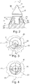
- figure 2 also shows the hard material element 22 that runs around the holding attachment 20 in the area of the conical surface 23 .
- the hard material element 22 is designed and arranged in such a way that its height h completely covers the height of the receptacle 21 in order to provide suitable protection against washing out.
- the build-up weld does not have the same thickness all the time. Rather, a varying thickness is conceivable in order to achieve an adapted wear behavior.
- the thickness of the hard material element 22 decreases in the direction of the central longitudinal axis of the cutting insert.
- the hard material element 22 can be applied circumferentially. However, it is also conceivable that the hard material element 22 is arranged over a curved area on the holding attachment 20, as is the case Figures 3 and 4 reveal. As figure 3 shows, the arc length I in the circumferential direction of the holding attachment 20 should preferably be selected to be greater than the diameter of the receptacle 21 or greater than the diameter of the head 33.
- the hard material element 22 does not have to have the same thickness in the circumferential direction either. Rather, it can also be provided that the thickness varies in the circumferential direction, preferably decreasing in the opposite direction to the feed direction.
- the hard material element 22 is formed by hard material segments that are attached to the holding attachment 20 .
- the hard material elements 22 can be formed, for example, from hard metal elements that are attached to the retaining attachment 22 in a materially bonded manner.
- the hard material elements 22 can be formed by hard material segments 22.1.
- the hard material segments 22.1 can be plate-shaped. It is also conceivable that as in figure 6 shown, the hard material segments 22.1 have a cover section 22.2, on which a fastening attachment 22.3 is formed. The hard material segments 22.1 are introduced into fastening receptacles 22.4 of the holding projection 22 with the fastening projection 22.3.
- FIG. 7 shows the structure of the cutting tip 31 as an example.
- a support body 31.1 for example consisting of hard metal, is used, on which an intermediate layer 31.2 is layered. It is also conceivable that two or several intermediate layers 31.2 are used.
- a cover layer 31.3 is applied to the intermediate layer 31.2.
- the cover layer 31.3 preferably has a proportion of polycrystalline diamond.
- the intermediate layer 31.2 also has a proportion of polycrystalline diamond.
- the proportion of polycrystalline diamond in the top layer 31.3 is higher than in the intermediate layer 31.2.
- FIG figure 8 shows a further embodiment of the invention.
- the carrier 10 essentially corresponds to the configuration of the carrier 10 according to FIG figure 1 , so that only the differences will be discussed below.
- the carrier 10 according to figure 1 has the carrier 10 according to figure 8 a retaining lug 25 which is formed on the base part 11 facing away from the fastening lug 14 .
- the holding attachment 25 has two bearing surfaces 26 and 27 which are at an angle to one another.
- the bearing surface 27 is directed in the feed direction V, the bearing surface 26 is directed opposite to the feed direction.
- the cutting element 40 is placed on the two bearing surfaces 26, 27 by means of a materially bonded connection, for example a soldered connection.
- the cutting element 40 has a head 43 which forms a mounting piece 45 .
- the attachment piece 45 has two lateral deflector surfaces 46 inclined in the direction of advance. At the back of the attachment piece 43 a projection 44 is formed.
- the cutting element 40 rests with the attachment piece 43 and the shoulder 44 on the bearing surfaces 26 and 27, as described above.
- the head 43 also carries a cutting tip 31, which in principle is constructed similarly to the cutting tip 31 according to the embodiment variants Figures 1 to 7 . However, the cutting tip 31 is constructed asymmetrically to its central longitudinal axis and has a larger volume in its radially outer area than in its radially inner area. In this way, an increased wear volume is offered in the area of the outer cutting edge of the cutting tip 31 .
- the cutting tip 31 is supported on the connecting piece 32 in the opposite direction to the feed direction on the head 33 and is attached here, preferably with an integral connection, in particular a soldered connection.
Landscapes
- Engineering & Computer Science (AREA)
- Mining & Mineral Resources (AREA)
- General Life Sciences & Earth Sciences (AREA)
- Geology (AREA)
- Geochemistry & Mineralogy (AREA)
- Mechanical Engineering (AREA)
- Life Sciences & Earth Sciences (AREA)
- Structural Engineering (AREA)
- Civil Engineering (AREA)
- Architecture (AREA)
- Earth Drilling (AREA)
- Drilling And Exploitation, And Mining Machines And Methods (AREA)
- Road Repair (AREA)
- Crushing And Pulverization Processes (AREA)
- Turning (AREA)
- Details Of Cutting Devices (AREA)
- Excavating Of Shafts Or Tunnels (AREA)
Claims (12)
- Dispositif de coupe pour une machine de travail du sol, en particulier une fraiseuse routière, avec un support (10) sur lequel est fixé un insert de coupe (30), le support (10) présentant une partie de base (11) sur laquelle est monté en saillie un appendice de retenue (20) avec un logement (21), l'insert de coupe (30) étant disposé au moins par zones dans le logement (21) et un appendice de fixation (14) étant disposé sur un côté de fixation opposé à l'appendice de retenue (20),l'insert de coupe (30) présentant une pointe de coupe (31) avec un matériau superdur, il appendice de retenue (20) portant un élément en matériau dur (22) au moins sur sa zone avant dans le sens d'avancement dans la zone entre la pointe de coupe (31) et la partie de base (11) etl'insert de coupe (30) présente une tête (33), il appendice de retenue (20) présentant une section d'appui (24) à l'opposé de la partie de base (11), et l'insert de coupe (30) recouvrant au moins partiellement la section d'appui (24) avec sa tête (33), caractérisé en ce queque l'élément en matériau dur (22) est guidé jusque dans la zone de la section d'appui (24) sous la tête (33) de l'insert de coupe (30).
- Dispositif de coupe selon la revendication 1,
caractérisé en ce que
que la pointe de coupe (31) est fixée à la tête (33), et que la tête (33) est constituée, au moins par zones, d'un matériau qui présente une résistance à l'usure inférieure à celle de la pointe de coupe (31) mais supérieure à celle du matériau de'l appendice de retenue (20). - Dispositif de coupe selon la revendication 2,
caractérisé en ce que
que la tête (33) est constituée au moins par zones de carbure de tungstène. - Dispositif de coupe selon l'une des revendications 1 à 3,
caractérisé en ce que
que l'insert de coupe (30) présente une tige (32) par laquelle il est inséré dans le logement (21) de l'appendice de retenue (20). - Dispositif de coupe selon la revendication 4,caractérisé en ce que l'insert de coupe (30) forme une transition concave dans la zone de transition entre la tête (33) et la tige (34),en ce que le logement (21) forme une transition convexe dans cette zone, et en ce qu'une zone de fente remplie de matériau composite, en particulier de matériau de brasage, est créée dans la zone de ces transitions.
- Dispositif de coupe selon l'une quelconque des revendications 1 à 5,
caractérisé en ce que
en ce que la tête (33) de l'insert de coupe (30) s'élargit à partir de la pointe de coupe en direction de l'appendice de retenue (20). - Dispositif de coupe selon l'une des revendications 1 à 6,
caractérisé en ce que
en ce que la pointe de coupe (31) présente un corps de support (31.1) qui est relié, de préférence brasé, à la tête (33) de l'insert de coupe (30), en ce qu'une ou plusieurs couches intermédiaires (31.2) sont appliquées sur le corps de support (31.1), en ce qu'une couche de recouvrement (31.3) est appliquée sur le côté le plus extérieur de la couche intermédiaire (31.2) qui est opposé au corps de support (31.1), et en ce que le matériau de la couche de recouvrement (31.3) est plus dur que le matériau de la couche intermédiaire (31.2). - Dispositif de coupe selon l'une des revendications 1 à 7,
caractérisé en ce que
que l'élément en matériau dur (22) est formé par un durcissement par rechargement, par exemple un soudage par rechargement, un durcissement par rechargement au plasma ou similaire et/ou que l'élément en matériau dur (22) est formé par un ou plusieurs segments en matériau dur (22.1) qui sont reliés à l'appendice de retenue (20). - Dispositif de coupe selon l'une des revendications 1 à 8,
caractérisé en ce que
en ce que l'insert de coupe (30) présente une surface déflectrice qui est conçue pour dévier, au moins par endroits, le matériau du sol enlevé par la pointe de coupe (31) devant la partie de base (11) du support (10). - Dispositif de coupe selon l'une des revendications 1 à 9,
caractérisé en ce que
en ce que l'élément en matériau dur (22) est disposé en forme d'arc autour du logement (21) de l' appendice de retenue (20), ou est appliqué en forme de cercle sur l' appendice de retenue (20) autour du logement (21). - Dispositif de coupe selon la revendication 10,
caractérisé en ce que
en ce que l'élément dur (22) en forme d'arc s'étend, dans la direction circonférentielle et dans la direction d'avance, en amont de l'insert de coupe (30), sur une longueur (I) qui est supérieure au diamètre ou à la dimension maximale en section transversale du logement (21). - Dispositif de coupe selon l'une quelconque des revendications 1 à 11, caractérisé en ce que
en ce que l'élément en matériau dur (22) présente une extension (h) dans la direction de l'axe longitudinal central du logement (21) qui est égale ou supérieure à la hauteur du logement (21) dans cette direction.
Applications Claiming Priority (2)
| Application Number | Priority Date | Filing Date | Title |
|---|---|---|---|
| DE102015112988.4A DE102015112988A1 (de) | 2015-08-06 | 2015-08-06 | Schneideinrichtung |
| PCT/EP2016/066430 WO2017021104A1 (fr) | 2015-08-06 | 2016-07-11 | Dispositif de coupe |
Publications (2)
| Publication Number | Publication Date |
|---|---|
| EP3332092A1 EP3332092A1 (fr) | 2018-06-13 |
| EP3332092B1 true EP3332092B1 (fr) | 2022-09-21 |
Family
ID=56404124
Family Applications (1)
| Application Number | Title | Priority Date | Filing Date |
|---|---|---|---|
| EP16736880.2A Active EP3332092B1 (fr) | 2015-08-06 | 2016-07-11 | Dispositif de coupe |
Country Status (7)
| Country | Link |
|---|---|
| US (1) | US10801322B2 (fr) |
| EP (1) | EP3332092B1 (fr) |
| JP (1) | JP6856622B2 (fr) |
| CN (2) | CN107923242B (fr) |
| AU (1) | AU2016304316B2 (fr) |
| DE (1) | DE102015112988A1 (fr) |
| WO (1) | WO2017021104A1 (fr) |
Families Citing this family (5)
| Publication number | Priority date | Publication date | Assignee | Title |
|---|---|---|---|---|
| DE102015112988A1 (de) | 2015-08-06 | 2017-02-09 | Betek Gmbh & Co. Kg | Schneideinrichtung |
| CN106978776A (zh) * | 2017-04-13 | 2017-07-25 | 苏州凯通工程机械有限公司 | 一种用于道路铣刨机的带柄刀具 |
| DE102017011131A1 (de) * | 2017-12-01 | 2019-06-06 | Bomag Gmbh | Hochverschleißfester, einstückiger Meißelspitzenkörper, Fräsmeißel für eine Bodenfräsmaschine, Fräswalze sowie Bodenfräsmaschine |
| USD906385S1 (en) * | 2020-01-21 | 2020-12-29 | Wirtgen Gmbh | Chisel holder |
| WO2022233589A1 (fr) * | 2021-05-03 | 2022-11-10 | Betek Gmbh & Co. Kg | Procédé de production d'un matériau de carbure cémenté ayant une phase liante renforcée |
Citations (5)
| Publication number | Priority date | Publication date | Assignee | Title |
|---|---|---|---|---|
| JPS63104487U (fr) * | 1986-12-23 | 1988-07-06 | ||
| EP0412287A2 (fr) * | 1989-08-11 | 1991-02-13 | VERSCHLEISS-TECHNIK DR.-ING. HANS WAHL GMBH & CO. | Pic ou outil dimilaire pour l'extraction de matières premières ou le recyclage |
| US20080035383A1 (en) * | 2006-08-11 | 2008-02-14 | Hall David R | Non-rotating Pick with a Pressed in Carbide Segment |
| WO2011128250A1 (fr) * | 2010-04-16 | 2011-10-20 | Element Six Holding Gmbh | Structure à face dure et corps comprenant celle-ci |
| DE102012101719A1 (de) * | 2012-03-01 | 2013-09-05 | Wirtgen Gmbh | Meißelhalter |
Family Cites Families (39)
| Publication number | Priority date | Publication date | Assignee | Title |
|---|---|---|---|---|
| US2053198A (en) * | 1934-11-01 | 1936-09-01 | Langlotz Barney | Fruit packer |
| US3343883A (en) * | 1965-06-11 | 1967-09-26 | Coal Industry Patents Ltd | Rotary cutter units for longwall mineral mining machines |
| SU402656A1 (ru) * | 1971-05-21 | 1973-10-19 | А. С. Ромашкин , А. Д. Сергеев | Резец для разрушения угля и горных пород |
| US4684176A (en) * | 1984-05-16 | 1987-08-04 | Den Besten Leroy E | Cutter bit device |
| DE3531787C1 (de) * | 1985-09-06 | 1986-06-26 | Berchem & Schaberg Gmbh, 4650 Gelsenkirchen | Auswechselbarer Zahn fuer ein Grab- und Brechwerkzeug mit Hartmetallspitze und Kantenbewehrung |
| JPS63104487A (ja) | 1986-10-22 | 1988-05-09 | Nitto Electric Ind Co Ltd | 光半導体装置 |
| JPH10246093A (ja) * | 1997-03-05 | 1998-09-14 | Ishikawajima Harima Heavy Ind Co Ltd | ローラカッタ |
| JPH11229777A (ja) | 1998-02-16 | 1999-08-24 | Ohbayashi Corp | 自由断面掘削機用掘削ビット |
| US6270165B1 (en) | 1999-10-22 | 2001-08-07 | Sandvik Rock Tools, Inc. | Cutting tool for breaking hard material, and a cutting cap therefor |
| AU750553B2 (en) * | 2000-08-07 | 2002-07-18 | Albert Daniel Dawood | A coal and rock cutting picks |
| JP4462771B2 (ja) * | 2001-02-15 | 2010-05-12 | 株式会社タンガロイ | 穿孔用ビット |
| JP4036728B2 (ja) * | 2002-11-05 | 2008-01-23 | 岡部株式会社 | 自穿孔ロックボルト用穿孔ビットおよびこれを用いた自穿孔ロックボルト |
| JP2005230888A (ja) * | 2004-02-23 | 2005-09-02 | Takeshi Honda | 掘削工具の製造方法 |
| US7600823B2 (en) | 2006-08-11 | 2009-10-13 | Hall David R | Pick assembly |
| DE102007007156A1 (de) * | 2007-02-09 | 2008-08-14 | Gerd Elfgen | Hartmetallspitze für einen Rundschaftmeißel |
| EP2053198A1 (fr) * | 2007-10-22 | 2009-04-29 | Element Six (Production) (Pty) Ltd. | Corps à pointe |
| US8540037B2 (en) * | 2008-04-30 | 2013-09-24 | Schlumberger Technology Corporation | Layered polycrystalline diamond |
| BE1018378A3 (nl) | 2008-12-12 | 2010-09-07 | Dredging Int | Sleepkop voor een sleephopperzuiger en werkwijze voor het baggeren met behulp van deze sleepkop. |
| US8789894B2 (en) * | 2009-01-13 | 2014-07-29 | Diamond Innovations, Inc. | Radial tool with superhard cutting surface |
| US8523290B2 (en) * | 2009-04-10 | 2013-09-03 | Kennametal Inc. | Rotatable cutting tool-tool holder-base assembly |
| AT508232B1 (de) | 2009-05-14 | 2011-05-15 | Sandvik Mining & Constr Oy | Schneidwerkzeug für eine bergbaumaschine |
| GB201000869D0 (en) * | 2010-01-20 | 2010-03-10 | Element Six Holding Gmbh | Superhard pick tool and method for making same |
| EP2547830A1 (fr) * | 2010-03-18 | 2013-01-23 | Southern Engineering Services Pty Ltd | Système de pic de coupe, d'usure et de montage pour machine minière |
| GB201006364D0 (en) | 2010-04-16 | 2010-06-02 | Univ Warwick | Intermittent control scanning electrochemical microscopy |
| JP5593873B2 (ja) | 2010-06-22 | 2014-09-24 | 三菱マテリアル株式会社 | ろう付け工具 |
| GB201011583D0 (en) * | 2010-07-09 | 2010-08-25 | Element Six Holding Gmbh | Hard face structure |
| DE102011051520B4 (de) | 2011-07-04 | 2014-10-23 | Wirtgen Gmbh | Meißelhalter |
| DE102011051525A1 (de) | 2011-07-04 | 2013-01-10 | Wirtgen Gmbh | Meißelhalter für eine Bodenbearbeitungsmaschine |
| US8668275B2 (en) * | 2011-07-06 | 2014-03-11 | David R. Hall | Pick assembly with a contiguous spinal region |
| GB201116414D0 (en) * | 2011-09-23 | 2011-11-02 | Element Six Holding Gmbh | Pick tool assembly, method for making same and method for refurbishing same |
| GB201118739D0 (en) | 2011-10-31 | 2011-12-14 | Element Six Abrasives Sa | Tip for a pick tool, method of making same and pick tool comprising same |
| US9103208B2 (en) * | 2012-06-12 | 2015-08-11 | Kennametal Inc. | Cutting bit with hard cutting tip centering and braze joint control feature |
| CN203161093U (zh) * | 2012-12-27 | 2013-08-28 | 三一重工股份有限公司 | 旋转式截齿、旋挖钻具及旋挖钻机 |
| US9074471B2 (en) * | 2013-08-05 | 2015-07-07 | Kennametal Inc. | Insert with offset apex for a cutter bit and a cutter bit having the same |
| DE102013110676A1 (de) * | 2013-09-26 | 2015-03-26 | Betek Gmbh & Co. Kg | Meißel |
| DE102013110680A1 (de) * | 2013-09-26 | 2015-03-26 | Betek Gmbh & Co. Kg | Meißelhalter und Kombination eines Meißelhalters mit einem Meißel |
| CN104032663A (zh) | 2014-05-29 | 2014-09-10 | 成都锋范科技有限公司 | 切刀可调式路面切割装置 |
| DE102014112966A1 (de) * | 2014-09-09 | 2016-03-31 | Betek Gmbh & Co. Kg | Vorrichtung mit einem Meißel |
| DE102015112988A1 (de) | 2015-08-06 | 2017-02-09 | Betek Gmbh & Co. Kg | Schneideinrichtung |
-
2015
- 2015-08-06 DE DE102015112988.4A patent/DE102015112988A1/de active Pending
-
2016
- 2016-07-11 AU AU2016304316A patent/AU2016304316B2/en active Active
- 2016-07-11 WO PCT/EP2016/066430 patent/WO2017021104A1/fr not_active Ceased
- 2016-07-11 CN CN201680045487.2A patent/CN107923242B/zh active Active
- 2016-07-11 CN CN202210352165.XA patent/CN114592419B/zh active Active
- 2016-07-11 US US15/749,246 patent/US10801322B2/en active Active
- 2016-07-11 JP JP2018506190A patent/JP6856622B2/ja active Active
- 2016-07-11 EP EP16736880.2A patent/EP3332092B1/fr active Active
Patent Citations (5)
| Publication number | Priority date | Publication date | Assignee | Title |
|---|---|---|---|---|
| JPS63104487U (fr) * | 1986-12-23 | 1988-07-06 | ||
| EP0412287A2 (fr) * | 1989-08-11 | 1991-02-13 | VERSCHLEISS-TECHNIK DR.-ING. HANS WAHL GMBH & CO. | Pic ou outil dimilaire pour l'extraction de matières premières ou le recyclage |
| US20080035383A1 (en) * | 2006-08-11 | 2008-02-14 | Hall David R | Non-rotating Pick with a Pressed in Carbide Segment |
| WO2011128250A1 (fr) * | 2010-04-16 | 2011-10-20 | Element Six Holding Gmbh | Structure à face dure et corps comprenant celle-ci |
| DE102012101719A1 (de) * | 2012-03-01 | 2013-09-05 | Wirtgen Gmbh | Meißelhalter |
Also Published As
| Publication number | Publication date |
|---|---|
| CN107923242B (zh) | 2022-07-19 |
| CN114592419B (zh) | 2025-06-27 |
| JP6856622B2 (ja) | 2021-04-07 |
| US10801322B2 (en) | 2020-10-13 |
| EP3332092A1 (fr) | 2018-06-13 |
| AU2016304316A1 (en) | 2018-02-22 |
| DE102015112988A1 (de) | 2017-02-09 |
| JP2018522154A (ja) | 2018-08-09 |
| AU2016304316B2 (en) | 2020-02-06 |
| CN114592419A (zh) | 2022-06-07 |
| WO2017021104A1 (fr) | 2017-02-09 |
| CN107923242A (zh) | 2018-04-17 |
| US20180223660A1 (en) | 2018-08-09 |
Similar Documents
| Publication | Publication Date | Title |
|---|---|---|
| EP3332092B1 (fr) | Dispositif de coupe | |
| EP2820243B1 (fr) | Porte-outil | |
| WO2015043884A2 (fr) | Trépan | |
| EP2766570A2 (fr) | Burin à tige | |
| EP2318656A1 (fr) | Porte-outil avec soudure comme element de protection contre l'usure | |
| DE4339245A1 (de) | Spiralbohrer | |
| DE102013218884B4 (de) | Spanendes Werkzeug | |
| DE19922208C2 (de) | Rundschaftmeißel | |
| EP3250788B1 (fr) | Burin, en particulier burin à queue d'aronde | |
| EP3405286B1 (fr) | Élément anti-usure pour dispositif de fragmentation | |
| EP3781785B1 (fr) | Trépan de fraisage | |
| EP3244717B1 (fr) | Outil de travail du sol | |
| EP3563000B1 (fr) | Combinaison d'outils comprenant un porte-outil et deux outils | |
| EP2766571A2 (fr) | Burin à tige et support | |
| DE102019105132B3 (de) | Arbeitswerkzeug, insbesondere Bodenbearbeitungswerkzeug | |
| EP3563038B1 (fr) | Porte-outil interchangeable | |
| EP4170096A1 (fr) | Outil de laminage pour un rouleau de traitement du sol | |
| WO2003069111A1 (fr) | Outil de perçage | |
| WO2017076669A1 (fr) | Outil pourvu d'un matériau dur | |
| DE19630653C1 (de) | Verschleißarme Abstürzung eines drehbar in einem Meißelhalter gelagerten Meißels | |
| EP1631733B1 (fr) | Element de retenue de burin a tige cylindrique pour une fraiseuse | |
| DE69622311T2 (de) | Schneidelement mit einer Oberfläche aus superhartem Werkstoff | |
| DE102016112204B4 (de) | Werkzeug und Hartstoffelement für ein Werkzeug | |
| EP2769055B2 (fr) | Élément de protection contre l'usure | |
| DE102016106148A1 (de) | Bearbeitungswerkzeug |
Legal Events
| Date | Code | Title | Description |
|---|---|---|---|
| STAA | Information on the status of an ep patent application or granted ep patent |
Free format text: STATUS: THE INTERNATIONAL PUBLICATION HAS BEEN MADE |
|
| PUAI | Public reference made under article 153(3) epc to a published international application that has entered the european phase |
Free format text: ORIGINAL CODE: 0009012 |
|
| STAA | Information on the status of an ep patent application or granted ep patent |
Free format text: STATUS: REQUEST FOR EXAMINATION WAS MADE |
|
| 17P | Request for examination filed |
Effective date: 20180306 |
|
| AK | Designated contracting states |
Kind code of ref document: A1 Designated state(s): AL AT BE BG CH CY CZ DE DK EE ES FI FR GB GR HR HU IE IS IT LI LT LU LV MC MK MT NL NO PL PT RO RS SE SI SK SM TR |
|
| AX | Request for extension of the european patent |
Extension state: BA ME |
|
| DAV | Request for validation of the european patent (deleted) | ||
| DAX | Request for extension of the european patent (deleted) | ||
| STAA | Information on the status of an ep patent application or granted ep patent |
Free format text: STATUS: EXAMINATION IS IN PROGRESS |
|
| 17Q | First examination report despatched |
Effective date: 20200512 |
|
| GRAP | Despatch of communication of intention to grant a patent |
Free format text: ORIGINAL CODE: EPIDOSNIGR1 |
|
| STAA | Information on the status of an ep patent application or granted ep patent |
Free format text: STATUS: GRANT OF PATENT IS INTENDED |
|
| INTG | Intention to grant announced |
Effective date: 20220323 |
|
| GRAJ | Information related to disapproval of communication of intention to grant by the applicant or resumption of examination proceedings by the epo deleted |
Free format text: ORIGINAL CODE: EPIDOSDIGR1 |
|
| STAA | Information on the status of an ep patent application or granted ep patent |
Free format text: STATUS: EXAMINATION IS IN PROGRESS |
|
| GRAP | Despatch of communication of intention to grant a patent |
Free format text: ORIGINAL CODE: EPIDOSNIGR1 |
|
| STAA | Information on the status of an ep patent application or granted ep patent |
Free format text: STATUS: GRANT OF PATENT IS INTENDED |
|
| INTC | Intention to grant announced (deleted) | ||
| INTG | Intention to grant announced |
Effective date: 20220527 |
|
| GRAS | Grant fee paid |
Free format text: ORIGINAL CODE: EPIDOSNIGR3 |
|
| GRAA | (expected) grant |
Free format text: ORIGINAL CODE: 0009210 |
|
| STAA | Information on the status of an ep patent application or granted ep patent |
Free format text: STATUS: THE PATENT HAS BEEN GRANTED |
|
| AK | Designated contracting states |
Kind code of ref document: B1 Designated state(s): AL AT BE BG CH CY CZ DE DK EE ES FI FR GB GR HR HU IE IS IT LI LT LU LV MC MK MT NL NO PL PT RO RS SE SI SK SM TR |
|
| REG | Reference to a national code |
Ref country code: GB Ref legal event code: FG4D Free format text: NOT ENGLISH |
|
| REG | Reference to a national code |
Ref country code: CH Ref legal event code: EP |
|
| REG | Reference to a national code |
Ref country code: IE Ref legal event code: FG4D Free format text: LANGUAGE OF EP DOCUMENT: GERMAN |
|
| REG | Reference to a national code |
Ref country code: DE Ref legal event code: R096 Ref document number: 502016015292 Country of ref document: DE |
|
| REG | Reference to a national code |
Ref country code: AT Ref legal event code: REF Ref document number: 1520049 Country of ref document: AT Kind code of ref document: T Effective date: 20221015 |
|
| REG | Reference to a national code |
Ref country code: LT Ref legal event code: MG9D |
|
| REG | Reference to a national code |
Ref country code: NL Ref legal event code: MP Effective date: 20220921 |
|
| PG25 | Lapsed in a contracting state [announced via postgrant information from national office to epo] |
Ref country code: SE Free format text: LAPSE BECAUSE OF FAILURE TO SUBMIT A TRANSLATION OF THE DESCRIPTION OR TO PAY THE FEE WITHIN THE PRESCRIBED TIME-LIMIT Effective date: 20220921 Ref country code: RS Free format text: LAPSE BECAUSE OF FAILURE TO SUBMIT A TRANSLATION OF THE DESCRIPTION OR TO PAY THE FEE WITHIN THE PRESCRIBED TIME-LIMIT Effective date: 20220921 Ref country code: NO Free format text: LAPSE BECAUSE OF FAILURE TO SUBMIT A TRANSLATION OF THE DESCRIPTION OR TO PAY THE FEE WITHIN THE PRESCRIBED TIME-LIMIT Effective date: 20221221 Ref country code: LV Free format text: LAPSE BECAUSE OF FAILURE TO SUBMIT A TRANSLATION OF THE DESCRIPTION OR TO PAY THE FEE WITHIN THE PRESCRIBED TIME-LIMIT Effective date: 20220921 Ref country code: LT Free format text: LAPSE BECAUSE OF FAILURE TO SUBMIT A TRANSLATION OF THE DESCRIPTION OR TO PAY THE FEE WITHIN THE PRESCRIBED TIME-LIMIT Effective date: 20220921 Ref country code: FI Free format text: LAPSE BECAUSE OF FAILURE TO SUBMIT A TRANSLATION OF THE DESCRIPTION OR TO PAY THE FEE WITHIN THE PRESCRIBED TIME-LIMIT Effective date: 20220921 |
|
| PG25 | Lapsed in a contracting state [announced via postgrant information from national office to epo] |
Ref country code: HR Free format text: LAPSE BECAUSE OF FAILURE TO SUBMIT A TRANSLATION OF THE DESCRIPTION OR TO PAY THE FEE WITHIN THE PRESCRIBED TIME-LIMIT Effective date: 20220921 Ref country code: GR Free format text: LAPSE BECAUSE OF FAILURE TO SUBMIT A TRANSLATION OF THE DESCRIPTION OR TO PAY THE FEE WITHIN THE PRESCRIBED TIME-LIMIT Effective date: 20221222 |
|
| PG25 | Lapsed in a contracting state [announced via postgrant information from national office to epo] |
Ref country code: SM Free format text: LAPSE BECAUSE OF FAILURE TO SUBMIT A TRANSLATION OF THE DESCRIPTION OR TO PAY THE FEE WITHIN THE PRESCRIBED TIME-LIMIT Effective date: 20220921 Ref country code: RO Free format text: LAPSE BECAUSE OF FAILURE TO SUBMIT A TRANSLATION OF THE DESCRIPTION OR TO PAY THE FEE WITHIN THE PRESCRIBED TIME-LIMIT Effective date: 20220921 Ref country code: PT Free format text: LAPSE BECAUSE OF FAILURE TO SUBMIT A TRANSLATION OF THE DESCRIPTION OR TO PAY THE FEE WITHIN THE PRESCRIBED TIME-LIMIT Effective date: 20230123 Ref country code: ES Free format text: LAPSE BECAUSE OF FAILURE TO SUBMIT A TRANSLATION OF THE DESCRIPTION OR TO PAY THE FEE WITHIN THE PRESCRIBED TIME-LIMIT Effective date: 20220921 Ref country code: CZ Free format text: LAPSE BECAUSE OF FAILURE TO SUBMIT A TRANSLATION OF THE DESCRIPTION OR TO PAY THE FEE WITHIN THE PRESCRIBED TIME-LIMIT Effective date: 20220921 |
|
| PG25 | Lapsed in a contracting state [announced via postgrant information from national office to epo] |
Ref country code: SK Free format text: LAPSE BECAUSE OF FAILURE TO SUBMIT A TRANSLATION OF THE DESCRIPTION OR TO PAY THE FEE WITHIN THE PRESCRIBED TIME-LIMIT Effective date: 20220921 Ref country code: PL Free format text: LAPSE BECAUSE OF FAILURE TO SUBMIT A TRANSLATION OF THE DESCRIPTION OR TO PAY THE FEE WITHIN THE PRESCRIBED TIME-LIMIT Effective date: 20220921 Ref country code: IS Free format text: LAPSE BECAUSE OF FAILURE TO SUBMIT A TRANSLATION OF THE DESCRIPTION OR TO PAY THE FEE WITHIN THE PRESCRIBED TIME-LIMIT Effective date: 20230121 Ref country code: EE Free format text: LAPSE BECAUSE OF FAILURE TO SUBMIT A TRANSLATION OF THE DESCRIPTION OR TO PAY THE FEE WITHIN THE PRESCRIBED TIME-LIMIT Effective date: 20220921 |
|
| REG | Reference to a national code |
Ref country code: DE Ref legal event code: R097 Ref document number: 502016015292 Country of ref document: DE |
|
| P01 | Opt-out of the competence of the unified patent court (upc) registered |
Effective date: 20230524 |
|
| PG25 | Lapsed in a contracting state [announced via postgrant information from national office to epo] |
Ref country code: NL Free format text: LAPSE BECAUSE OF FAILURE TO SUBMIT A TRANSLATION OF THE DESCRIPTION OR TO PAY THE FEE WITHIN THE PRESCRIBED TIME-LIMIT Effective date: 20220921 Ref country code: AL Free format text: LAPSE BECAUSE OF FAILURE TO SUBMIT A TRANSLATION OF THE DESCRIPTION OR TO PAY THE FEE WITHIN THE PRESCRIBED TIME-LIMIT Effective date: 20220921 |
|
| PLBE | No opposition filed within time limit |
Free format text: ORIGINAL CODE: 0009261 |
|
| STAA | Information on the status of an ep patent application or granted ep patent |
Free format text: STATUS: NO OPPOSITION FILED WITHIN TIME LIMIT |
|
| PG25 | Lapsed in a contracting state [announced via postgrant information from national office to epo] |
Ref country code: DK Free format text: LAPSE BECAUSE OF FAILURE TO SUBMIT A TRANSLATION OF THE DESCRIPTION OR TO PAY THE FEE WITHIN THE PRESCRIBED TIME-LIMIT Effective date: 20220921 |
|
| 26N | No opposition filed |
Effective date: 20230622 |
|
| PG25 | Lapsed in a contracting state [announced via postgrant information from national office to epo] |
Ref country code: SI Free format text: LAPSE BECAUSE OF FAILURE TO SUBMIT A TRANSLATION OF THE DESCRIPTION OR TO PAY THE FEE WITHIN THE PRESCRIBED TIME-LIMIT Effective date: 20220921 |
|
| PG25 | Lapsed in a contracting state [announced via postgrant information from national office to epo] |
Ref country code: MC Free format text: LAPSE BECAUSE OF FAILURE TO SUBMIT A TRANSLATION OF THE DESCRIPTION OR TO PAY THE FEE WITHIN THE PRESCRIBED TIME-LIMIT Effective date: 20220921 |
|
| PG25 | Lapsed in a contracting state [announced via postgrant information from national office to epo] |
Ref country code: MC Free format text: LAPSE BECAUSE OF FAILURE TO SUBMIT A TRANSLATION OF THE DESCRIPTION OR TO PAY THE FEE WITHIN THE PRESCRIBED TIME-LIMIT Effective date: 20220921 |
|
| REG | Reference to a national code |
Ref country code: CH Ref legal event code: PL |
|
| REG | Reference to a national code |
Ref country code: BE Ref legal event code: MM Effective date: 20230731 |
|
| PG25 | Lapsed in a contracting state [announced via postgrant information from national office to epo] |
Ref country code: LU Free format text: LAPSE BECAUSE OF NON-PAYMENT OF DUE FEES Effective date: 20230711 |
|
| PG25 | Lapsed in a contracting state [announced via postgrant information from national office to epo] |
Ref country code: LU Free format text: LAPSE BECAUSE OF NON-PAYMENT OF DUE FEES Effective date: 20230711 |
|
| REG | Reference to a national code |
Ref country code: IE Ref legal event code: MM4A |
|
| PG25 | Lapsed in a contracting state [announced via postgrant information from national office to epo] |
Ref country code: CH Free format text: LAPSE BECAUSE OF NON-PAYMENT OF DUE FEES Effective date: 20230731 |
|
| PG25 | Lapsed in a contracting state [announced via postgrant information from national office to epo] |
Ref country code: IT Free format text: LAPSE BECAUSE OF FAILURE TO SUBMIT A TRANSLATION OF THE DESCRIPTION OR TO PAY THE FEE WITHIN THE PRESCRIBED TIME-LIMIT Effective date: 20220921 Ref country code: BE Free format text: LAPSE BECAUSE OF NON-PAYMENT OF DUE FEES Effective date: 20230731 |
|
| PG25 | Lapsed in a contracting state [announced via postgrant information from national office to epo] |
Ref country code: IE Free format text: LAPSE BECAUSE OF NON-PAYMENT OF DUE FEES Effective date: 20230711 |
|
| PG25 | Lapsed in a contracting state [announced via postgrant information from national office to epo] |
Ref country code: IE Free format text: LAPSE BECAUSE OF NON-PAYMENT OF DUE FEES Effective date: 20230711 |
|
| REG | Reference to a national code |
Ref country code: AT Ref legal event code: MM01 Ref document number: 1520049 Country of ref document: AT Kind code of ref document: T Effective date: 20230711 |
|
| PG25 | Lapsed in a contracting state [announced via postgrant information from national office to epo] |
Ref country code: AT Free format text: LAPSE BECAUSE OF NON-PAYMENT OF DUE FEES Effective date: 20230711 |
|
| PG25 | Lapsed in a contracting state [announced via postgrant information from national office to epo] |
Ref country code: AT Free format text: LAPSE BECAUSE OF NON-PAYMENT OF DUE FEES Effective date: 20230711 |
|
| PG25 | Lapsed in a contracting state [announced via postgrant information from national office to epo] |
Ref country code: BG Free format text: LAPSE BECAUSE OF FAILURE TO SUBMIT A TRANSLATION OF THE DESCRIPTION OR TO PAY THE FEE WITHIN THE PRESCRIBED TIME-LIMIT Effective date: 20220921 |
|
| PG25 | Lapsed in a contracting state [announced via postgrant information from national office to epo] |
Ref country code: BG Free format text: LAPSE BECAUSE OF FAILURE TO SUBMIT A TRANSLATION OF THE DESCRIPTION OR TO PAY THE FEE WITHIN THE PRESCRIBED TIME-LIMIT Effective date: 20220921 |
|
| PG25 | Lapsed in a contracting state [announced via postgrant information from national office to epo] |
Ref country code: CY Free format text: LAPSE BECAUSE OF FAILURE TO SUBMIT A TRANSLATION OF THE DESCRIPTION OR TO PAY THE FEE WITHIN THE PRESCRIBED TIME-LIMIT; INVALID AB INITIO Effective date: 20160711 |
|
| PG25 | Lapsed in a contracting state [announced via postgrant information from national office to epo] |
Ref country code: HU Free format text: LAPSE BECAUSE OF FAILURE TO SUBMIT A TRANSLATION OF THE DESCRIPTION OR TO PAY THE FEE WITHIN THE PRESCRIBED TIME-LIMIT; INVALID AB INITIO Effective date: 20160711 |
|
| PGFP | Annual fee paid to national office [announced via postgrant information from national office to epo] |
Ref country code: DE Payment date: 20250722 Year of fee payment: 10 |
|
| PGFP | Annual fee paid to national office [announced via postgrant information from national office to epo] |
Ref country code: GB Payment date: 20250722 Year of fee payment: 10 |
|
| PGFP | Annual fee paid to national office [announced via postgrant information from national office to epo] |
Ref country code: FR Payment date: 20250725 Year of fee payment: 10 |
|
| PG25 | Lapsed in a contracting state [announced via postgrant information from national office to epo] |
Ref country code: TR Free format text: LAPSE BECAUSE OF FAILURE TO SUBMIT A TRANSLATION OF THE DESCRIPTION OR TO PAY THE FEE WITHIN THE PRESCRIBED TIME-LIMIT Effective date: 20220921 |