EP3333558B1 - Flexibler tastsensor und herstellungsverfahren dafür - Google Patents
Flexibler tastsensor und herstellungsverfahren dafür Download PDFInfo
- Publication number
- EP3333558B1 EP3333558B1 EP16835254.0A EP16835254A EP3333558B1 EP 3333558 B1 EP3333558 B1 EP 3333558B1 EP 16835254 A EP16835254 A EP 16835254A EP 3333558 B1 EP3333558 B1 EP 3333558B1
- Authority
- EP
- European Patent Office
- Prior art keywords
- strain gauge
- layer
- sensor
- strain
- tactile sensor
- Prior art date
- Legal status (The legal status is an assumption and is not a legal conclusion. Google has not performed a legal analysis and makes no representation as to the accuracy of the status listed.)
- Active
Links
Images





Classifications
-
- G—PHYSICS
- G01—MEASURING; TESTING
- G01L—MEASURING FORCE, STRESS, TORQUE, WORK, MECHANICAL POWER, MECHANICAL EFFICIENCY, OR FLUID PRESSURE
- G01L1/00—Measuring force or stress, in general
- G01L1/20—Measuring force or stress, in general by measuring variations in ohmic resistance of solid materials or of electrically-conductive fluids; by making use of electrokinetic cells, i.e. liquid-containing cells wherein an electrical potential is produced or varied upon the application of stress
- G01L1/22—Measuring force or stress, in general by measuring variations in ohmic resistance of solid materials or of electrically-conductive fluids; by making use of electrokinetic cells, i.e. liquid-containing cells wherein an electrical potential is produced or varied upon the application of stress using resistance strain gauges
- G01L1/2287—Measuring force or stress, in general by measuring variations in ohmic resistance of solid materials or of electrically-conductive fluids; by making use of electrokinetic cells, i.e. liquid-containing cells wherein an electrical potential is produced or varied upon the application of stress using resistance strain gauges constructional details of the strain gauges
-
- B—PERFORMING OPERATIONS; TRANSPORTING
- B25—HAND TOOLS; PORTABLE POWER-DRIVEN TOOLS; MANIPULATORS
- B25J—MANIPULATORS; CHAMBERS PROVIDED WITH MANIPULATION DEVICES
- B25J13/00—Controls for manipulators
- B25J13/08—Controls for manipulators by means of sensing devices, e.g. viewing or touching devices
- B25J13/081—Touching devices, e.g. pressure-sensitive
- B25J13/084—Tactile sensors
-
- G—PHYSICS
- G01—MEASURING; TESTING
- G01B—MEASURING LENGTH, THICKNESS OR SIMILAR LINEAR DIMENSIONS; MEASURING ANGLES; MEASURING AREAS; MEASURING IRREGULARITIES OF SURFACES OR CONTOURS
- G01B7/00—Measuring arrangements characterised by the use of electric or magnetic techniques
- G01B7/16—Measuring arrangements characterised by the use of electric or magnetic techniques for measuring the deformation in a solid, e.g. by resistance strain gauge
- G01B7/18—Measuring arrangements characterised by the use of electric or magnetic techniques for measuring the deformation in a solid, e.g. by resistance strain gauge using change in resistance
-
- G—PHYSICS
- G01—MEASURING; TESTING
- G01L—MEASURING FORCE, STRESS, TORQUE, WORK, MECHANICAL POWER, MECHANICAL EFFICIENCY, OR FLUID PRESSURE
- G01L1/00—Measuring force or stress, in general
- G01L1/20—Measuring force or stress, in general by measuring variations in ohmic resistance of solid materials or of electrically-conductive fluids; by making use of electrokinetic cells, i.e. liquid-containing cells wherein an electrical potential is produced or varied upon the application of stress
- G01L1/205—Measuring force or stress, in general by measuring variations in ohmic resistance of solid materials or of electrically-conductive fluids; by making use of electrokinetic cells, i.e. liquid-containing cells wherein an electrical potential is produced or varied upon the application of stress using distributed sensing elements
-
- G—PHYSICS
- G01—MEASURING; TESTING
- G01L—MEASURING FORCE, STRESS, TORQUE, WORK, MECHANICAL POWER, MECHANICAL EFFICIENCY, OR FLUID PRESSURE
- G01L1/00—Measuring force or stress, in general
- G01L1/20—Measuring force or stress, in general by measuring variations in ohmic resistance of solid materials or of electrically-conductive fluids; by making use of electrokinetic cells, i.e. liquid-containing cells wherein an electrical potential is produced or varied upon the application of stress
- G01L1/22—Measuring force or stress, in general by measuring variations in ohmic resistance of solid materials or of electrically-conductive fluids; by making use of electrokinetic cells, i.e. liquid-containing cells wherein an electrical potential is produced or varied upon the application of stress using resistance strain gauges
-
- G—PHYSICS
- G01—MEASURING; TESTING
- G01L—MEASURING FORCE, STRESS, TORQUE, WORK, MECHANICAL POWER, MECHANICAL EFFICIENCY, OR FLUID PRESSURE
- G01L1/00—Measuring force or stress, in general
- G01L1/20—Measuring force or stress, in general by measuring variations in ohmic resistance of solid materials or of electrically-conductive fluids; by making use of electrokinetic cells, i.e. liquid-containing cells wherein an electrical potential is produced or varied upon the application of stress
- G01L1/22—Measuring force or stress, in general by measuring variations in ohmic resistance of solid materials or of electrically-conductive fluids; by making use of electrokinetic cells, i.e. liquid-containing cells wherein an electrical potential is produced or varied upon the application of stress using resistance strain gauges
- G01L1/2268—Arrangements for correcting or for compensating unwanted effects
-
- G—PHYSICS
- G01—MEASURING; TESTING
- G01L—MEASURING FORCE, STRESS, TORQUE, WORK, MECHANICAL POWER, MECHANICAL EFFICIENCY, OR FLUID PRESSURE
- G01L5/00—Apparatus for, or methods of, measuring force, work, mechanical power, or torque, specially adapted for specific purposes
- G01L5/16—Apparatus for, or methods of, measuring force, work, mechanical power, or torque, specially adapted for specific purposes for measuring several components of force
- G01L5/161—Apparatus for, or methods of, measuring force, work, mechanical power, or torque, specially adapted for specific purposes for measuring several components of force using variations in ohmic resistance
- G01L5/1627—Apparatus for, or methods of, measuring force, work, mechanical power, or torque, specially adapted for specific purposes for measuring several components of force using variations in ohmic resistance of strain gauges
-
- G—PHYSICS
- G01—MEASURING; TESTING
- G01L—MEASURING FORCE, STRESS, TORQUE, WORK, MECHANICAL POWER, MECHANICAL EFFICIENCY, OR FLUID PRESSURE
- G01L5/00—Apparatus for, or methods of, measuring force, work, mechanical power, or torque, specially adapted for specific purposes
- G01L5/22—Apparatus for, or methods of, measuring force, work, mechanical power, or torque, specially adapted for specific purposes for measuring the force applied to control members, e.g. control members of vehicles, triggers
- G01L5/226—Apparatus for, or methods of, measuring force, work, mechanical power, or torque, specially adapted for specific purposes for measuring the force applied to control members, e.g. control members of vehicles, triggers to manipulators, e.g. the force due to gripping
- G01L5/228—Apparatus for, or methods of, measuring force, work, mechanical power, or torque, specially adapted for specific purposes for measuring the force applied to control members, e.g. control members of vehicles, triggers to manipulators, e.g. the force due to gripping using tactile array force sensors
Definitions
- the present invention relates to a flexible tactile sensor and a method for manufacturing the same, and more particularly, to a flexible tactile sensor capable of sensing a touch on both sides and a method for manufacturing the same.
- a tactile sensor is a sensor that measures a local force or pressure affected by a contact parameter, i.e., a contact, between the sensor and an object.
- Tactile sensors may not only be used in various medical devices for surgery, cancer diagnosis, and the like, and medical procedures but also be applied to various fields such as a virtual environment implementation field, a tactile display field, and the like.
- a force/torque sensor of six degrees of freedom used for the wrist of an industrial robot and a tactile sensor capable of sensing a contact force and momentary slip for a gripper of a robot have already been developed.
- the already developed tactile sensors include a 3-axis force component-based tactile sensor capable of sensing information regarding a contact force in X, Y, and Z axis directions, and the like.
- Korean Patent Registration No. 10-0703082 discloses a flexible tactile sensor and a method for manufacturing the same.
- This patent provides a tactile sensor including a membrane layer having a sensing region and formed of a photosensitive polymer, a membrane support layer formed on a lower surface of the membrane layer to have a window defining the sensing region and including at least two photosensitive polymer layers, a plurality of metal strain gauges formed on the lower surface of the membrane layer such that at least a portion thereof is positioned in the sensing region, and arranged to face each other, a first metal wire formed on a lower surface of the membrane layer so as to be connected to each of the plurality of metal strain gauges, and a second metal wire formed between the at least two photosensitive polymer layers so as to be connected to each of the plurality of metal strain gauges.
- Korean Patent Registration No. 10-0997108 discloses a tactile sensor and a method for manufacturing the same.
- This patent provides a miniaturized tactile sensor capable of sensing an action even when a magnitude of the action on the tactile sensor from the outside is small, and a method for manufacturing the same including a simplified manufacturing process, contributing to a reduction manufacturing cost and manufacturing time and enhancement of productivity.
- US 7 094 061 B1 discloses an integral strain measurement layer for use in an assembly printed circuit board.
- strain sensitive layers are arranged symmetrically on both sides of the insulating substrate layer of the circuit board. Additional conductive coating layers cover each of the strain sensitive layers.
- a flexible layered tactile sensor is formed from a flexible support layer, an electronic layer mounted to one surface thereof, wherein the electronic layer supports a sensing layer, which is in turn covered by a protective layer.
- the layered sensing structure is formed on only one surface / side of the support layer.
- the present invention provides a flexible tactile sensor according to claim 1 and a method for manufacturing the same according to claim 6.
- the present invention provides a flexible tactile sensor capable of sensing a force on both sides thereof and a method for manufacturing the same.
- the present invention also provides a flexible tactile sensor which is reduced in thickness to obtain high flexibility and enables sensing on both sides to increase accuracy of sensing, and a method for manufacturing the same.
- the present invention also provides a flexible tactile sensor having a simplified sensor structure to enhance productivity, and a method for manufacturing the same.
- the polymer layer may be a polyimide layer.
- the first metal layer and the second metal layer may be nickel-chromium (Ni-Cr) layers.
- the first strain gauge and the second strain gauge may be formed such that longitudinal axes thereof are at a predetermined angle with respect to a vertical axis of a plane.
- first strain gauge and the second strain gauge may be spaced apart from each other and formed such that longitudinal axes thereof have a ' ⁇ ' shape.
- the first strain gauge and the second strain gauge may have a continuous ' ' shape.
- the first strain gauge and the second strain gauge may have an 'X' shape.
- the first strain gauge and the second strain gauge may be formed such that lengths of line widths and lengths of gaps between lines thereof are different.
- a length of a line width of the first strain gauge may be 40 to 90 ⁇ m and a length of a gap between lines may be 110 to 160 ⁇ m
- a length of a line width of the second strain gauge may be 50 to 100 ⁇ m and a length of a gap between lines may be 100 to 150 ⁇ m.
- the second sensor layer may include a third strain gauge and a third metal wire connected to one end and the other end of the third strain gauge and a fourth strain gauge and a fourth metal wire connected to one end and the other end of the fourth strain gauge.
- first strain gauge and the second strain gauge may be formed such that longitudinal axes thereof are perpendicular to each other.
- a method for manufacturing a flexible tactile sensor includes: forming a first metal layer and a second metal layer on upper and lower surfaces of a polymer layer, respectively; patterning a strain gauge on each of an upper surface of the first metal layer and a lower surface of the second metal layer; patterning a metal wire connected to each of the strain gauges; and forming a first cover layer protecting the strain gauge and the metal wire formed on the upper surface of the first metal layer and a second cover layer protecting the strain gauge and the metal wire formed on the lower surface of the second metal layer.
- the patterning of a strain gauge may include: patterning a first strain gauge and a second strain gauge on the upper surface of the first metal layer and the lower surface of the second metal layer, respectively.
- the first strain gauge and the second strain gauge may be patterned such that longitudinal axes thereof are at a predetermined angle with respect to a vertical axis of a plane.
- the first strain gauge and the second strain gauge may be patterned such that lengths of line widths and gaps between lines thereof are different.
- the patterning of a strain gauge may include patterning a first strain gauge on an upper surface of the first metal layer and patterning a second strain gauge on a lower surface of the second metal layer.
- the first strain gauge and the second strain gauge may be patterned such that longitudinal axis thereof are perpendicular to each other.
- the flexible tactile sensor according to an embodiment of the present invention may provide an accurate sensing result by sensing a force from both sides thereof.
- a thickness of the sensor may be reduced to increase flexibility, and since it is possible to sense from both sides, accuracy of sensing may be increased.
- the flexible tactile sensor and the method for manufacturing the same according to an embodiment of the present invention may enhance productivity of the sensor through a simplified sensor structure.
- first and second may be used to describe various components, such components must not be understood as being limited to the above terms.
- a first component may be named a second component and, similarly, the second component may also be named the first component.
- FIG. 1 is a schematic cross-sectional view of a flexible tactile sensor according to an embodiment of the present invention.
- a flexible tactile sensor includes a polymer layer 110, a first metal layer 120 formed on the polymer layer 110, a first sensor layer 130 formed on the first metal layer 120 and including a strain gauge changed in a resistance value according to strain (or deformation) and a metal wire connected to the strain gauge, a first cover layer 150 protecting the first sensor layer 130, a second metal layer 121 formed on a lower surface of the polymer layer 110, a second sensor layer 131 formed on a lower surface of the second metal layer 121 and including a strain gauge changed in a resistance value according to strain and a metal wire connected to the strain gauge, and a second cover layer 151 protecting the second sensor layer 131.
- the polymer layer 110 may be flexibly bent by an external force, while maintaining a structure of the sensor.
- the polymer layer 110 may be a polyimide (PI) layer.
- PI polyimide
- Polyimide has high thermal stability and stable physical and chemical properties and is thin and flexible.
- the polymer layer 110 may have a thickness of 25 ⁇ m.
- the first metal layer 120 and the second metal layer 121 are formed on an upper surface (in an outward direction) and a lower surface (or in an outward direction) of the polymer layer 110, respectively.
- the first metal layer 120 and the second metal layer 121 may be formed by depositing nickel-chromium (Ni-Cr) on the upper and lower surfaces of the polymer layer 110, respectively.
- the first metal layer 120 and the second metal layer 121 may each have a thickness of 400 ⁇ .
- the first metal layer 120 and the second metal layer 121 may be deposited only at positions where a strain gauge is to be patterned.
- the first sensor layer 130 includes a strain gauge formed on an upper surface of the first metal layer 120 and having a resistance value changed according to strain and a metal wire connected to the strain gauge. After the strain gauge is patterned on top of the first metal layer 120, a metal wire may be connected to the strain gauge. After the metal wire is connected to one end and the other end of the strain gauge, the strain gate may be connected to a first electrode and a second electrode. The metal wire may be patterned with copper (Cu) and connected to the strain gauge. In an embodiment, the first sensor layer 130 may have a thickness of 13 ⁇ m.
- the second sensor layer 131 includes a strain gauge formed on a lower surface of the second metal layer 121 and having a resistance value changed according to strain and a metal wire connected to the strain gauge.
- a description of the second sensor layer 131 is the same as that of the first sensor layer 130.
- the first cover layer 150 is provided on the first sensor layer 130 to protect the first sensor layer 130 and the second cover layer 151 is provided under the second sensor layer 131 to protect the second sensor layer 131.
- the cover layers 150 and 151 are polyester (PET) layers.
- a first adhesive layer 140 may be formed on the first sensor layer 130 and the first cover layer 150 may be adhered to the first sensor layer 130 via the first adhesive layer 140.
- a second adhesive layer 141 may be formed under the second sensor layer 131 and the second cover layer 151 may be adhered to the second sensor layer 131 via the second adhesive layer 141.
- the cover layers 150 and 151 may be adhered to the sensor layers 130 and 131.
- the flexible tactile sensor of FIG. 1 has sensors on both sides thereof to sense a force on both sides. For example, when the flexible tactile sensor is bent to one side by an external force, the flexible tactile sensor may sense the bending from both sides (bending up and bending down), and thus, accuracy of sensing may be improved. Further, the flexible tactile sensor may measure a normal force applied to a point thereof.
- FIG. 2 is a specific cross-sectional view of the flexible tactile sensor of FIG. 1 .
- the first sensor layer 130 includes a first strain gauge 132a and a first metal wire 132b connected to one end and the other end of the first strain gauge 132a and a second strain gauge 134a and a second metal wire 134b connected to one end and the other end of the second strain gauge 134a.
- the first strain gauge 132a and the second strain gauge 134a may be spaced apart from each other.
- the first strain gauge 132a and the first metal wire 132b correspond to a sensor module for driving (or a driving sensor module), and the second strain gauge 134a and the second metal wire 134b correspond to a sensor module for correction (or a correction sensor module).
- the first strain gauge 132a outputs a first sensing value via the first metal wire 132b
- the second strain gauge 134a outputs a second sensing value for correcting the first sensing value via the second metal wire 134b.
- a monitoring server may include a module or an algorithm for correcting a sensing value and correct an error of a sensing value based on a temperature difference between the sensor modules using the first sensing value output from the driving sensor module and the second sensing value output from the correction sensor module.
- the second sensor layer 131 includes a third strain gauge 136a and a third metal wire 136b connected to one end and the other end of the third strain gauge 136a and a fourth strain gauge 138a and a fourth metal wire 138b connected to one end and the other end of the fourth strain gauge 138a.
- the third strain gauge 136a and the fourth strain gauge 138a may be spaced apart from each other.
- the third strain gauge 136a and the third metal wire 136b correspond to a driving sensor module
- the fourth strain gauge 138a and the fourth metal wire 138b correspond to a correction sensor module.
- the third strain gauge 136a may output a third sensing value via the third metal wire 136b
- the fourth strain gauge 138a may output a fourth sensing value for correcting the third sensing value via the fourth metal wire 138b.
- the first metal layer and the second metal layer may be deposited on the entirety of the polymer layer 110 or may be deposited only at positions 120a, 120b, 121a, and 121b where the strain gauges are patterned.
- FIG. 3 is a view illustrating strain gauges and metal wires of the flexible tactile sensor of FIG. 2 .
- the strain gauges 132a, 134a, 136a, and 138a may be patterned in a continuous ' shape.
- a metal wire may be connected to each of the ends of the strain gauges.
- lengths of line widths and lengths of gaps between lines of the strain gauges 132a and 136a of the driving sensor module and lengths of line widths and gaps between lines of the strain gauges 134a and 138a of the correction sensor module may be different.
- the lengths of the line widths and the lengths of the gaps between the lines may be implemented to be different depending on an application target of the sensor, a main measurement direction of a force, and the like.
- the lengths of the line widths of the strain gauges 132a and 136a of the driving sensor module may be 40 to 90 ⁇ m
- the lengths of the gaps between the lines may be 110 to 160 ⁇ m
- the lengths of the line widths of the strain gauges 134a and 138a may be 50 to 100 ⁇ m and the lengths of the gaps between the lines may be 100 to 150 ⁇ m.
- the lengths of the line widths of the strain gauges 132a and 136a of the driving sensor module may be 65 ⁇ m and the lengths of the gaps between the lines may be 135 ⁇ m, and the lengths of the line widths of strain gauges 134a and 138a may be 75 ⁇ m and the lengths of the gaps between the lines may be 125 ⁇ m.
- the strain gauges 132a, 134a, 136a, and 138a may be formed such that an expected folding line or bending line of the flexible tactile sensor is horizontal to longitudinal axes 310, 312, 320, and 322 of the strain gauges 132a, 134a, 136a, and 138a. As the folding line or bending line of the flexible tactile sensor becomes horizontal to the longitudinal axis 310, 312, 320, and 322 of the strain gauges 132a, 134a, 136a, and 138a, strain of the strain gauges is increased to increase measurement accuracy.
- the expected folding line or bending line of the flexible tactile sensor may be assumed by a designer in advance in consideration of an application target, an application position, a measurement target force, and the like, and the strain gauges 132a, 134a, 136a, may be formed based on the corresponding assumption.
- the first strain gauge 132a of the driving sensor module and the second strain gauge 134a of the correction sensor module may be arranged such that the longitudinal axes 310 and 312 thereof are at a predetermined angle with respect to a vertical axis of the plane.
- the first strain gauge 132a and the second strain gauge 134a may be oblique to each other.
- first strain gauge 132a and the second strain gauge 134a may be spaced from each other and the longitudinal axes 310 and 312 thereof intersect at the top to form a ' ⁇ ' shape.
- the third strain gauge 136a of the driving sensor module and the fourth strain gauge 138a of the correction sensor module may be formed such that the longitudinal axes 320 and 322 are ata predetermined angle with respect to a vertical axis of the plane.
- the third strain gauge 136a and the fourth strain gauge 138a may be oblique to each other.
- the third strain gauge 136a and the fourth strain gauge 138a may be spaced from each other and the longitudinal axes 320 and 322 intersect at the bottom to form a ' ⁇ ' shape.
- first strain gauge 132a and the third strain gauge 136a may be formed at opposite positions corresponding to each other and the second strain gauge 134a and the fourth strain gauge 138a may be formed at opposite positions corresponding to each other.
- first strain gauge 132a and the second strain gauge 134a on one side and the third strain gauge 136a and the fourth strain gauge 138a on the other side may be formed to intersect with each other.
- first strain gauge 132a, the third strain gauge 136a, the second strain gauge 134a, and the fourth strain gauge 138a may be formed to intersect with each other in this order.
- the flexible tactile sensor configured as described above is equipped with the sensors on both sides to accurately sense a force on both sides.
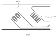
- FIG. 4 is a view illustrating an embodiment of a flexible tactile sensor of FIG. 2 .
- a driving sensor module 410 and a correction sensor module 420 are provided on one side of the flexible tactile sensor.
- the strain gauges of the tactile sensor module may be formed on the same side as illustrated in FIG. 4 or on different sides.
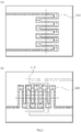
- FIG. 5 is a view illustrating another embodiment of a tactile sensor module.
- a first strain gauge 510 may be formed on a first side ((a) of FIG. 5 ) and a second strain gauge 520 may be formed on a second side (opposite side of the first side) ((b) of FIG. 5 ).
- the first strain gauge 510 and the second strain gauge 520 may be formed such that the longitudinal axes thereof are perpendicular to each other.
- the first strain gauge 510 and the second strain gauge 520 may be formed such that longitudinal axes thereof intersect with each other slantingly.
- the first strain gauge 510 may be formed such that the longitudinal axis thereof is perpendicular to a horizontal plane of the first side ((a) of FIG. 5 ) and the second strain gauge 520 may be formed so that the longitudinal axis thereof are parallel to the horizontal plane of the second side ((b) of FIG. 5 ), so as to be perpendicular to each other.
- a user may check a strain direction based on an applied force.
- the first strain gauge 510 corresponds to a strain gauge of a first driving sensor module and the second strain gauge 520 corresponds to a strain gauge of a second driving sensor module.
- the monitoring server (or a manager) may include a module or algorithm for correcting a sensing value in a predetermined manner and correct the sensing value output from each driving sensor module.
- the first strain gauge 510 corresponds to the strain gauge of the driving sensor module
- the second strain gauge 520 may correspond to the strain gauge of the correction sensor module.
- FIG. 6 is a view illustrating another embodiment of a tactile sensor module.
- a first strain gauge 610 and a second strain gauge 620 may be formed on the same plane. In another embodiment, the first strain gauge 610 and the second strain gauge 620 may be formed on different sides.
- the strain gauges 610 and 620 may be patterned in an 'X' shape, and metal wires may be connected to ends of the strain gauges 610 and 620, respectively.
- a longitudinal axis of the first strain gauge 610 and a longitudinal axis of the second strain gauge 620 may be in different directions.
- the first strain gauge 610 may be formed such that the longitudinal axis is parallel to a horizontal plane of the corresponding surface
- the second strain gauge 620 may be formed such that the longitudinal axis is perpendicular to the horizontal plane of the corresponding surface.
- the longitudinal axis of first strain gauge 610 and the longitudinal axis of the second strain gauge 620 may be in the same direction.
- the first strain gauge 610 may correspond to a strain gauge of a first driving sensor module and the second strain gauge 620 may correspond to a strain gauge of a second driving sensor module.
- the monitoring server (or the manager) may include a module or algorithm for correcting a sensing value in a predetermined manner and may correct a sensing value output from each driving sensor module.
- the first strain gauge 610 corresponds to a strain gauge of a driving sensor module and the second strain gauge 620 may correspond to a strain gauge of a correction sensor module.
- each flexible tactile sensor includes a strain gauge of the same pattern, but a single flexible tactile sensor may include strain gauges of different patterns.
- the single flexible tactile sensor may include both a strain gauge in a ' ' shape and a strain gauge in an 'X' shape.
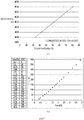
- FIG. 7 is a graph illustrating characteristics of the flexible tactile sensor of FIG. 4 .
- FIG. 7 is a graph illustrating a variation in resistance of a flexible tactile sensor over temperature. Referring to (a) of FIG. 7 , it can be seen that the resistance of the manufactured flexible tactile sensor increases linearly as temperature increases.
- FIG. 7 is a graph illustrating an output value of the flexible tactile sensor over externally applied force. Referring to (b) of FIG. 7 , it can be seen that the output value of the manufactured flexible tactile sensor linearly increases as the external applied force increases.
- FIG. 8 is a graph illustrating a variation in resistance over bending radius of the flexible tactile sensor of FIG. 4 .
- the flexible tactile sensor When the bending radius is within 5 mm, the flexible tactile sensor may be used stably
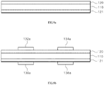
- FIGS. 9A to 9D are views illustrating a method of manufacturing a flexible tactile sensor according to an embodiment of the present invention.
- FIGS. 9A to 9D illustrate a method of simultaneously manufacturing both sides of a flexible tactile sensor.
- a first metal layer 120 and a second metal layer 121 are formed on upper and lower surfaces of a polymer layer 110, respectively ( FIG. 9A ).
- the first metal layer 120 and the second metal layer 121 may be formed by depositing nickel-chromium (Ni-Cr) on the upper and lower surfaces of the polymer layer 110.
- strain gauges 132a, 134a, 136a and 138a are patterned on an upper surface of the first metal layer 120 and a lower surface of the second metal layer 121, respectively ( FIG. 9B ).
- each of the strain gauges 132a, 134a, 136a, and 138a may be patterned in a continuous ' ' shape.
- each of the strain gauges 132a, 134a, 136a, 138a may be patterned in an 'X' shape.
- lengths of line widths and lengths of gaps between lines of the strain gauges 132a and 136a of the driving sensor module and the strain gauges 134a and 138a of the correction sensor module may be different.
- the strain gauges 132a and 136a of a driving sensor module and the strain gauges 134a and 138a of a correction sensor module may be formed such that the longitudinal axes thereof are at a predetermined angle with respect to the vertical axis of the plane.
- the first strain gauge may be patterned on an upper surface of the first metal layer and the second strain gauge may be patterned on a lower surface of the second metal layer.
- the first strain gauge and the second strain gauge may be patterned such that longitudinal axes thereof are perpendicular to each other.
- strain gauges 132a, 134a, 136a, and 138a are patterned.
- a first cover layer 150 protecting the strain gauge and the metal wire formed on the upper surface of the first metal layer 120 and a second cover layer 150 protecting the strain gauge and the metal wire formed on the lower surface of the second metal layer 121 are formed ( FIG. 9D )
- cover layers 150 and 151 may be adhered after applying an adhesive to the strain gauges and the metal wires formed on the metal layers 120 and 121 or attaching an adhesive film thereto.
- FIGS. 9A to 9D illustrate the method of simultaneously manufacturing both sides of a flexible tactile sensor, but one side thereof may be manufactured first and the other side may then be manufactured.
- a specific manufacturing process of each layer excluding manufacturing order is the same as that described with reference to FIGS. 9A to 9D .
- the present invention relates to a flexible tactile sensor and a method of manufacturing the same, and more particularly, to a flexible tactile sensor capable of sensing a touch on both sides thereof and a method of manufacturing the same.
Landscapes
- Physics & Mathematics (AREA)
- General Physics & Mathematics (AREA)
- Engineering & Computer Science (AREA)
- Chemical & Material Sciences (AREA)
- Analytical Chemistry (AREA)
- Human Computer Interaction (AREA)
- Robotics (AREA)
- Mechanical Engineering (AREA)
- Force Measurement Appropriate To Specific Purposes (AREA)
- Measurement Of Length, Angles, Or The Like Using Electric Or Magnetic Means (AREA)
Claims (6)
- Biegsamer, berührungsempfindlicher Sensor, umfassend:eine Polymerschicht (110),eine erste Metallschicht (120), die auf einer obenliegenden Fläche der Polymerschicht (110) gebildet ist,eine erste Sensorschicht (130), die auf einer obenliegenden Fläche der ersten Metallschicht (120) gebildet ist und einen Dehnungsmessstreifen (132a, 134a, 510, 520, 610, 620), der sich in Abhängigkeit von der Dehnung in einen Widerstandswert ändert, sowie einen Metalldraht (132b, 134b) aufweist, der dazu dient, einen Messwert auszugeben und mit dem Dehnungsmessstreifen (132a, 134a, 510, 520, 610, 620) verbunden ist;eine erste Deckschicht (150), die aus Polyester ist und die erste Sensorschicht (130) schützt;eine zweite Metallschicht (121), die auf einer untenliegenden Fläche der Polymerschicht (110) gebildet ist;eine zweite Sensorschicht (131), die auf einer untenliegenden Fläche der zweiten Metallschicht (121) gebildet ist und einen Dehnungsmessstreifen (136a, 138a),der sich in Abhängigkeit von der Dehnung in einen Widerstandswert ändert, sowie einen Metalldraht (136b, 138b) aufweist, der dazu dient, einen Messwert auszugeben und mit dem Dehnungsmessstreifen (136a, 138a) verbunden ist;eine zweite Deckschicht (151), die aus Polyester ist und die zweite Sensorschicht (131) schützt,wobei die erste Sensorschicht (130) aufweist:einen ersten Dehnungsmessstreifen (132a, 510, 610), der dafür ausgelegt ist, über einen ersten Metalldraht (132b),der mit jedem der Enden des ersten Dehnungsmessstreifens (132a, 510, 610) verbunden ist, einen ersten Messwert auszugeben; undeinen zweiten Dehnungsmessstreifen (134a, 520, 620), der dafür ausgelegt ist, über einen zweiten Metalldraht (134b),der mit jedem der Enden des zweiten Dehnungsmessstreifens (134a, 520, 620) verbunden ist, einen zweiten Messwert auszugeben.
- Biegsamer berührungsempfindlicher Sensor nach Anspruch 1, wobei
der erste Dehnungsmessstreifen (132a) und der zweite Dehnungsmessstreifen (134a) jeweils in einer durchgehenden '' -Form ausgebildet sind, wobei sie sich jeweils entlang einer eigenen Längsachse (310, 312) erstrecken, wobei die Längsachsen sich schneiden.
- Biegsamer berührungsempfindlicher Sensor nach Anspruch 2, wobei
der erste Dehnungsmessstreifen (132a) und der zweite Dehnungsmessstreifen (134a) voneinander beabstandet sind und derart ausgebildet sind, dass ihre Längsachsen (310, 312) eine '∧' -Form aufweisen. - Biegsamer berührungsempfindlicher Sensor nach Anspruch 1, wobei
der erste Dehnungsmessstreifen (132a, 510) und der zweite Dehnungsmessstreifen (134a, 520) in einer durchgehenden ''- Form ausgebildet sind, wobei die Längen der Linien sowie die Breiten und Längen zwischen den Linien unterschiedlich sind. - Biegsamer berührungsempfindlicher Sensor nach Anspruch 1, wobei
der erste Dehnungsmessstreifen (610) und der zweite Dehnungsmessstreifen (620) eine 'X'-Form aufweisen. - Verfahren zur Herstellung eines biegsamen berührungsempfindlichen Sensors, wobei das Verfahren umfasst:Bilden einer ersten Metallschicht (120) auf einer obenliegenden Fläche einer Polymerschicht (110);mustergetreues Aufbringen eines ersten und eines zweiten Dehnungsmessstreifens (132a, 134a) in einer durchgehenden '' -Form auf einer obenliegenden Fläche der ersten Metallschicht (120),mustergetreues Aufbringen von Metalldrähten (132b, 134b), die mit beiden der ersten und zweiten Dehnungsmessstreifen (132a, 134a) verbunden sind;Bilden einer ersten Deckschicht (150), die aus Polyester besteht, wobei sie die Dehnungsmessstreifen (132a, 134a) und die Metalldrähte (132b, 134b) schützt, die auf der obenliegenden Fläche der ersten Metallschicht (120) gebildet sind;Bilden einer zweiten Metallschicht (121) auf einer untenliegenden Fläche der Polymerschicht (110);mustergetreues Aufbringen eines Dehnungsmessstreifens (136a, 138a) in einer durchgehenden '' -Form auf einer untenliegenden Oberfläche der zweiten Metallschicht (121);mustergetreues Aufbringen eines Metalldrahts (136b, 138b), der mit dem Dehnungsmessstreifen (136a, 138a) verbunden ist; undBilden einer zweien Deckschicht (151), die aus Polyester besteht, wobei sie den Dehnungsmessstreifen (136a, 138a) und den Metalldraht (136b, 138b) schützt, die auf der untenliegenden Fläche der zweiten Metallschicht (121) gebildet sind.
Applications Claiming Priority (2)
| Application Number | Priority Date | Filing Date | Title |
|---|---|---|---|
| KR1020150111692A KR101817966B1 (ko) | 2015-08-07 | 2015-08-07 | 플렉서블 촉각 센서 및 이의 제조 방법 |
| PCT/KR2016/001245 WO2017026610A1 (ko) | 2015-08-07 | 2016-02-04 | 플렉서블 촉각 센서 및 이의 제조 방법 |
Publications (3)
| Publication Number | Publication Date |
|---|---|
| EP3333558A1 EP3333558A1 (de) | 2018-06-13 |
| EP3333558A4 EP3333558A4 (de) | 2019-03-06 |
| EP3333558B1 true EP3333558B1 (de) | 2021-04-14 |
Family
ID=57983767
Family Applications (1)
| Application Number | Title | Priority Date | Filing Date |
|---|---|---|---|
| EP16835254.0A Active EP3333558B1 (de) | 2015-08-07 | 2016-02-04 | Flexibler tastsensor und herstellungsverfahren dafür |
Country Status (5)
| Country | Link |
|---|---|
| US (1) | US10578501B2 (de) |
| EP (1) | EP3333558B1 (de) |
| KR (1) | KR101817966B1 (de) |
| CN (1) | CN108139283B (de) |
| WO (1) | WO2017026610A1 (de) |
Families Citing this family (23)
| Publication number | Priority date | Publication date | Assignee | Title |
|---|---|---|---|---|
| CN110192172B (zh) * | 2017-01-21 | 2022-10-14 | 深圳纽迪瑞科技开发有限公司 | 压力感应式结构及电子产品 |
| EP3642582B1 (de) * | 2017-06-22 | 2024-07-31 | Ezmems Ltd. | Sensorelemente auf dünnen folien/filmen |
| US10119869B1 (en) * | 2017-12-21 | 2018-11-06 | Tactotek Oy | Method for manufacturing a strain gauge device, a strain gauge device, and the use of the device |
| KR102048829B1 (ko) * | 2017-12-28 | 2019-11-26 | 주식회사 지에스엠 | 차축 부착형 차량 축하중 센서모듈 |
| JP7332770B2 (ja) * | 2018-07-23 | 2023-08-23 | ミネベアミツミ株式会社 | 触覚センサ |
| JP7193262B2 (ja) * | 2018-07-23 | 2022-12-20 | ミネベアミツミ株式会社 | 触覚センサ |
| JP6783830B2 (ja) * | 2018-08-27 | 2020-11-11 | ミネベアミツミ株式会社 | 滑りセンサ |
| JP7008618B2 (ja) | 2018-08-28 | 2022-01-25 | ミネベアミツミ株式会社 | 電池パック |
| CN109860384B (zh) * | 2019-01-17 | 2022-07-01 | 业成科技(成都)有限公司 | 应变规驱动压电装置 |
| CN109781315B (zh) * | 2019-02-02 | 2020-08-25 | 五邑大学 | 一种触觉传感器 |
| CN110186487B (zh) * | 2019-06-03 | 2020-10-27 | 北京航空航天大学 | 一种变阻式柔性传感单元及其制作方法 |
| US12491057B2 (en) * | 2019-10-23 | 2025-12-09 | Solventum Intellectual Properties Company | Force sensor system |
| JP7402060B2 (ja) * | 2020-01-15 | 2023-12-20 | ミネベアミツミ株式会社 | タイヤ |
| JP7185649B2 (ja) * | 2020-01-27 | 2022-12-07 | ミネベアミツミ株式会社 | タイヤ |
| KR102394469B1 (ko) | 2020-05-29 | 2022-05-04 | 연세대학교 산학협력단 | 3차원 다공성 구조체, 이의 제조방법 및 이를 이용한 감압 센서 |
| KR102388964B1 (ko) | 2020-06-17 | 2022-04-22 | 연세대학교 산학협력단 | 3차원 다공성 구조체, 이의 제조방법 및 이를 이용한 감압 센서 |
| JP7762513B2 (ja) * | 2021-05-19 | 2025-10-30 | ニデックドライブテクノロジー株式会社 | 歪みセンサおよび動力伝達装置 |
| CN113282192A (zh) * | 2021-05-24 | 2021-08-20 | 维沃移动通信有限公司 | 压感模组及电子设备 |
| DE102021117868A1 (de) * | 2021-07-12 | 2023-01-12 | Valeo Schalter Und Sensoren Gmbh | Bedienvorrichtung für ein Kraftfahrzeug mit einem spezifischen Aufbau eines Sensors mit Dehnungsmesselementen |
| CN113340480B (zh) * | 2021-07-14 | 2023-12-01 | 苏州能斯达电子科技有限公司 | 一种柔性压力传感器及其制备方法 |
| CN114674483B (zh) * | 2022-04-08 | 2023-03-24 | 浙江大学 | 一种具有高切向角分辨率的三维力柔性触觉传感器 |
| KR102673678B1 (ko) * | 2022-04-11 | 2024-06-10 | 동국대학교 산학협력단 | 전도성 천 기반의 유연 촉각센서 |
| CN115323337B (zh) * | 2022-10-11 | 2023-01-10 | 松诺盟科技有限公司 | 一种纳米薄膜复合应变传感器及其制备方法与应用 |
Family Cites Families (21)
| Publication number | Priority date | Publication date | Assignee | Title |
|---|---|---|---|---|
| GB560260A (en) * | 1942-10-08 | 1944-03-28 | Frank Aughtie | Improvements in or relating to electrical strain gauges |
| US5375474A (en) * | 1992-08-12 | 1994-12-27 | The United States Of America As Represented By The United States National Aeronautics And Space Administration | Compensated high temperature strain gage |
| JP2000082608A (ja) | 1998-07-09 | 2000-03-21 | Denso Corp | 感圧抵抗体及び感圧センサ |
| JP2001015882A (ja) * | 1999-07-02 | 2001-01-19 | Nec Corp | 歪みゲージ内蔵回路基板およびその製造方法 |
| US7123026B2 (en) * | 2001-01-23 | 2006-10-17 | Nippon Telegraph And Telephone Corporation | Surface shape recognition sensor and method of manufacturing the same |
| US6948377B2 (en) * | 2003-12-08 | 2005-09-27 | Honeywell International, Inc. | Method and apparatus for detecting the strain levels imposed on a circuit board |
| US7096748B2 (en) * | 2004-07-28 | 2006-08-29 | Lsi Logic Corporation | Embedded strain gauge in printed circuit boards |
| US20060185446A1 (en) * | 2005-02-18 | 2006-08-24 | Speckhart Frank H | Printed strain gage for vehicle seats |
| US7094061B1 (en) * | 2005-02-22 | 2006-08-22 | Vishay Measurements Group, Inc. | Printed circuit board with integral strain gage |
| KR100703082B1 (ko) | 2005-07-08 | 2007-04-06 | 삼성전기주식회사 | 플렉서블 촉각센서 및 그 제조방법 |
| ES2294934B1 (es) * | 2006-07-06 | 2008-11-16 | Fundacio Privada Per A La Innovacio Textil D'igualada | Sensor textil de esfuerzos de presion y/o tension y/o torsion. |
| KR100997108B1 (ko) | 2008-05-19 | 2010-11-29 | 한국표준과학연구원 | 촉각센서와 그 제조방법 |
| TWI388813B (zh) | 2009-08-31 | 2013-03-11 | Universal Cement Corp | 壓力感測器以及具有壓力感測器之拳擊機 |
| DE102010002274A1 (de) * | 2010-02-24 | 2011-08-25 | Robert Bosch GmbH, 70469 | Vorrichtung zur Messung von Torsionen, Biegungen und dergleichen sowie entsprechendes Herstellungsverfahren |
| DE102010052991A1 (de) * | 2010-11-30 | 2012-05-31 | Giesecke & Devrient Gmbh | Portabler Datenträger |
| EP2758760B1 (de) * | 2011-09-24 | 2021-02-17 | President and Fellows of Harvard College | Elastischer dehnungssensor |
| JP5827583B2 (ja) * | 2012-03-08 | 2015-12-02 | タカノ株式会社 | 面圧センサ |
| US8997588B2 (en) * | 2012-09-29 | 2015-04-07 | Stryker Corporation | Force detecting mat with multiple sensor types |
| KR101542971B1 (ko) * | 2013-12-27 | 2015-08-07 | 현대자동차 주식회사 | 압저항 센서 |
| KR101788664B1 (ko) * | 2015-08-07 | 2017-10-20 | 전자부품연구원 | 사용자 움직임 모니터링 방법 및 이를 수행하는 시스템 |
| WO2017026611A1 (ko) * | 2015-08-07 | 2017-02-16 | 전자부품연구원 | 스마트 베드, 이를 이용한 사용자 상태 모니터링 시스템 및 사용자 상태 모니터링 방법 |
-
2015
- 2015-08-07 KR KR1020150111692A patent/KR101817966B1/ko active Active
-
2016
- 2016-02-04 CN CN201680046396.0A patent/CN108139283B/zh active Active
- 2016-02-04 EP EP16835254.0A patent/EP3333558B1/de active Active
- 2016-02-04 WO PCT/KR2016/001245 patent/WO2017026610A1/ko not_active Ceased
-
2018
- 2018-02-07 US US15/891,259 patent/US10578501B2/en active Active
Non-Patent Citations (1)
| Title |
|---|
| None * |
Also Published As
| Publication number | Publication date |
|---|---|
| CN108139283A (zh) | 2018-06-08 |
| EP3333558A1 (de) | 2018-06-13 |
| KR20170017563A (ko) | 2017-02-15 |
| US20180172527A1 (en) | 2018-06-21 |
| WO2017026610A1 (ko) | 2017-02-16 |
| EP3333558A4 (de) | 2019-03-06 |
| KR101817966B1 (ko) | 2018-01-11 |
| CN108139283B (zh) | 2021-04-13 |
| US10578501B2 (en) | 2020-03-03 |
Similar Documents
| Publication | Publication Date | Title |
|---|---|---|
| EP3333558B1 (de) | Flexibler tastsensor und herstellungsverfahren dafür | |
| Qiu et al. | A path beyond metal and silicon: polymer/nanomaterial composites for stretchable strain sensors | |
| US10585456B2 (en) | Flexible display device having bending sensing device | |
| KR101066672B1 (ko) | 어레이형 정전용량식 센서 | |
| US10678363B2 (en) | Pressure sensor and display device | |
| CN205091721U (zh) | 电子设备和用于电子设备的力传感器 | |
| US8640549B2 (en) | Strain gage and manufacturing method thereof | |
| US9257632B2 (en) | Physical quantity sensor and process for production thereof | |
| US8049591B2 (en) | Tactile sensor for curved surface and manufacturing method thereof | |
| EP3588040B1 (de) | Dehnelement und kraftsensor mit dehnelement | |
| EP2585801B1 (de) | Widerstandstemperatursensor | |
| US9972768B2 (en) | Actuator structure and method | |
| US10309846B2 (en) | Magnetic field cancellation for strain sensors | |
| US11761837B2 (en) | Multi-axial tactile sensor | |
| TW202202804A (zh) | 用於彎曲感測器之非均勻電極間隔 | |
| JP2025084185A (ja) | 検出装置 | |
| EP3588039A1 (de) | Elastischer körper und kraftsensor mit dem elastischen körper | |
| Qaiser et al. | Design, mechanics, and operation of spiral-interconnect based networked sensor for stretchable electronics | |
| CN113167662B (zh) | 具有集成电路和传感器的装置及形成其的方法 | |
| JP5815356B2 (ja) | 面圧センサ | |
| CN117848553A (zh) | 压力传感器以及可穿戴传感器 | |
| JP2008224406A (ja) | 物理量センサ | |
| TWI396835B (zh) | Piezoelectric tactile sensor and its manufacturing method | |
| JP5647567B2 (ja) | 応力センサ | |
| CN118518001B (zh) | 一种含缝阵列的电阻柔性应变传感器及其制备方法 |
Legal Events
| Date | Code | Title | Description |
|---|---|---|---|
| STAA | Information on the status of an ep patent application or granted ep patent |
Free format text: STATUS: THE INTERNATIONAL PUBLICATION HAS BEEN MADE |
|
| PUAI | Public reference made under article 153(3) epc to a published international application that has entered the european phase |
Free format text: ORIGINAL CODE: 0009012 |
|
| STAA | Information on the status of an ep patent application or granted ep patent |
Free format text: STATUS: REQUEST FOR EXAMINATION WAS MADE |
|
| 17P | Request for examination filed |
Effective date: 20180223 |
|
| AK | Designated contracting states |
Kind code of ref document: A1 Designated state(s): AL AT BE BG CH CY CZ DE DK EE ES FI FR GB GR HR HU IE IS IT LI LT LU LV MC MK MT NL NO PL PT RO RS SE SI SK SM TR |
|
| AX | Request for extension of the european patent |
Extension state: BA ME |
|
| DAV | Request for validation of the european patent (deleted) | ||
| DAX | Request for extension of the european patent (deleted) | ||
| A4 | Supplementary search report drawn up and despatched |
Effective date: 20190204 |
|
| RIC1 | Information provided on ipc code assigned before grant |
Ipc: G01L 1/22 20060101AFI20190129BHEP Ipc: G01L 5/22 20060101ALI20190129BHEP Ipc: G06F 3/041 20060101ALI20190129BHEP Ipc: G01L 5/16 20060101ALI20190129BHEP Ipc: H01L 21/768 20060101ALI20190129BHEP Ipc: G01L 1/20 20060101ALI20190129BHEP Ipc: G01B 7/16 20060101ALI20190129BHEP Ipc: B25J 13/08 20060101ALI20190129BHEP |
|
| STAA | Information on the status of an ep patent application or granted ep patent |
Free format text: STATUS: EXAMINATION IS IN PROGRESS |
|
| 17Q | First examination report despatched |
Effective date: 20200409 |
|
| GRAP | Despatch of communication of intention to grant a patent |
Free format text: ORIGINAL CODE: EPIDOSNIGR1 |
|
| STAA | Information on the status of an ep patent application or granted ep patent |
Free format text: STATUS: GRANT OF PATENT IS INTENDED |
|
| RIC1 | Information provided on ipc code assigned before grant |
Ipc: G01L 5/16 20200101ALI20201012BHEP Ipc: G01L 5/161 20200101ALI20201012BHEP Ipc: G06F 3/041 20060101ALI20201012BHEP Ipc: H01L 21/768 20060101ALI20201012BHEP Ipc: B25J 13/08 20060101ALI20201012BHEP Ipc: G01L 5/22 20060101ALI20201012BHEP Ipc: G01L 1/20 20060101ALI20201012BHEP Ipc: G01L 1/22 20060101AFI20201012BHEP Ipc: G01B 7/16 20060101ALI20201012BHEP |
|
| INTG | Intention to grant announced |
Effective date: 20201105 |
|
| GRAS | Grant fee paid |
Free format text: ORIGINAL CODE: EPIDOSNIGR3 |
|
| GRAA | (expected) grant |
Free format text: ORIGINAL CODE: 0009210 |
|
| STAA | Information on the status of an ep patent application or granted ep patent |
Free format text: STATUS: THE PATENT HAS BEEN GRANTED |
|
| AK | Designated contracting states |
Kind code of ref document: B1 Designated state(s): AL AT BE BG CH CY CZ DE DK EE ES FI FR GB GR HR HU IE IS IT LI LT LU LV MC MK MT NL NO PL PT RO RS SE SI SK SM TR |
|
| REG | Reference to a national code |
Ref country code: GB Ref legal event code: FG4D |
|
| REG | Reference to a national code |
Ref country code: CH Ref legal event code: EP |
|
| REG | Reference to a national code |
Ref country code: DE Ref legal event code: R096 Ref document number: 602016056210 Country of ref document: DE |
|
| REG | Reference to a national code |
Ref country code: IE Ref legal event code: FG4D |
|
| REG | Reference to a national code |
Ref country code: AT Ref legal event code: REF Ref document number: 1382836 Country of ref document: AT Kind code of ref document: T Effective date: 20210515 |
|
| REG | Reference to a national code |
Ref country code: LT Ref legal event code: MG9D |
|
| REG | Reference to a national code |
Ref country code: AT Ref legal event code: MK05 Ref document number: 1382836 Country of ref document: AT Kind code of ref document: T Effective date: 20210414 |
|
| REG | Reference to a national code |
Ref country code: NL Ref legal event code: MP Effective date: 20210414 |
|
| PG25 | Lapsed in a contracting state [announced via postgrant information from national office to epo] |
Ref country code: FI Free format text: LAPSE BECAUSE OF FAILURE TO SUBMIT A TRANSLATION OF THE DESCRIPTION OR TO PAY THE FEE WITHIN THE PRESCRIBED TIME-LIMIT Effective date: 20210414 Ref country code: LT Free format text: LAPSE BECAUSE OF FAILURE TO SUBMIT A TRANSLATION OF THE DESCRIPTION OR TO PAY THE FEE WITHIN THE PRESCRIBED TIME-LIMIT Effective date: 20210414 Ref country code: AT Free format text: LAPSE BECAUSE OF FAILURE TO SUBMIT A TRANSLATION OF THE DESCRIPTION OR TO PAY THE FEE WITHIN THE PRESCRIBED TIME-LIMIT Effective date: 20210414 Ref country code: BG Free format text: LAPSE BECAUSE OF FAILURE TO SUBMIT A TRANSLATION OF THE DESCRIPTION OR TO PAY THE FEE WITHIN THE PRESCRIBED TIME-LIMIT Effective date: 20210714 Ref country code: HR Free format text: LAPSE BECAUSE OF FAILURE TO SUBMIT A TRANSLATION OF THE DESCRIPTION OR TO PAY THE FEE WITHIN THE PRESCRIBED TIME-LIMIT Effective date: 20210414 Ref country code: NL Free format text: LAPSE BECAUSE OF FAILURE TO SUBMIT A TRANSLATION OF THE DESCRIPTION OR TO PAY THE FEE WITHIN THE PRESCRIBED TIME-LIMIT Effective date: 20210414 |
|
| PG25 | Lapsed in a contracting state [announced via postgrant information from national office to epo] |
Ref country code: PT Free format text: LAPSE BECAUSE OF FAILURE TO SUBMIT A TRANSLATION OF THE DESCRIPTION OR TO PAY THE FEE WITHIN THE PRESCRIBED TIME-LIMIT Effective date: 20210816 Ref country code: PL Free format text: LAPSE BECAUSE OF FAILURE TO SUBMIT A TRANSLATION OF THE DESCRIPTION OR TO PAY THE FEE WITHIN THE PRESCRIBED TIME-LIMIT Effective date: 20210414 Ref country code: NO Free format text: LAPSE BECAUSE OF FAILURE TO SUBMIT A TRANSLATION OF THE DESCRIPTION OR TO PAY THE FEE WITHIN THE PRESCRIBED TIME-LIMIT Effective date: 20210714 Ref country code: RS Free format text: LAPSE BECAUSE OF FAILURE TO SUBMIT A TRANSLATION OF THE DESCRIPTION OR TO PAY THE FEE WITHIN THE PRESCRIBED TIME-LIMIT Effective date: 20210414 Ref country code: SE Free format text: LAPSE BECAUSE OF FAILURE TO SUBMIT A TRANSLATION OF THE DESCRIPTION OR TO PAY THE FEE WITHIN THE PRESCRIBED TIME-LIMIT Effective date: 20210414 Ref country code: GR Free format text: LAPSE BECAUSE OF FAILURE TO SUBMIT A TRANSLATION OF THE DESCRIPTION OR TO PAY THE FEE WITHIN THE PRESCRIBED TIME-LIMIT Effective date: 20210715 Ref country code: LV Free format text: LAPSE BECAUSE OF FAILURE TO SUBMIT A TRANSLATION OF THE DESCRIPTION OR TO PAY THE FEE WITHIN THE PRESCRIBED TIME-LIMIT Effective date: 20210414 Ref country code: IS Free format text: LAPSE BECAUSE OF FAILURE TO SUBMIT A TRANSLATION OF THE DESCRIPTION OR TO PAY THE FEE WITHIN THE PRESCRIBED TIME-LIMIT Effective date: 20210814 |
|
| REG | Reference to a national code |
Ref country code: DE Ref legal event code: R097 Ref document number: 602016056210 Country of ref document: DE |
|
| PG25 | Lapsed in a contracting state [announced via postgrant information from national office to epo] |
Ref country code: ES Free format text: LAPSE BECAUSE OF FAILURE TO SUBMIT A TRANSLATION OF THE DESCRIPTION OR TO PAY THE FEE WITHIN THE PRESCRIBED TIME-LIMIT Effective date: 20210414 Ref country code: RO Free format text: LAPSE BECAUSE OF FAILURE TO SUBMIT A TRANSLATION OF THE DESCRIPTION OR TO PAY THE FEE WITHIN THE PRESCRIBED TIME-LIMIT Effective date: 20210414 Ref country code: EE Free format text: LAPSE BECAUSE OF FAILURE TO SUBMIT A TRANSLATION OF THE DESCRIPTION OR TO PAY THE FEE WITHIN THE PRESCRIBED TIME-LIMIT Effective date: 20210414 Ref country code: DK Free format text: LAPSE BECAUSE OF FAILURE TO SUBMIT A TRANSLATION OF THE DESCRIPTION OR TO PAY THE FEE WITHIN THE PRESCRIBED TIME-LIMIT Effective date: 20210414 Ref country code: CZ Free format text: LAPSE BECAUSE OF FAILURE TO SUBMIT A TRANSLATION OF THE DESCRIPTION OR TO PAY THE FEE WITHIN THE PRESCRIBED TIME-LIMIT Effective date: 20210414 Ref country code: SM Free format text: LAPSE BECAUSE OF FAILURE TO SUBMIT A TRANSLATION OF THE DESCRIPTION OR TO PAY THE FEE WITHIN THE PRESCRIBED TIME-LIMIT Effective date: 20210414 Ref country code: SK Free format text: LAPSE BECAUSE OF FAILURE TO SUBMIT A TRANSLATION OF THE DESCRIPTION OR TO PAY THE FEE WITHIN THE PRESCRIBED TIME-LIMIT Effective date: 20210414 |
|
| PLBE | No opposition filed within time limit |
Free format text: ORIGINAL CODE: 0009261 |
|
| STAA | Information on the status of an ep patent application or granted ep patent |
Free format text: STATUS: NO OPPOSITION FILED WITHIN TIME LIMIT |
|
| 26N | No opposition filed |
Effective date: 20220117 |
|
| PG25 | Lapsed in a contracting state [announced via postgrant information from national office to epo] |
Ref country code: IS Free format text: LAPSE BECAUSE OF FAILURE TO SUBMIT A TRANSLATION OF THE DESCRIPTION OR TO PAY THE FEE WITHIN THE PRESCRIBED TIME-LIMIT Effective date: 20210814 Ref country code: AL Free format text: LAPSE BECAUSE OF FAILURE TO SUBMIT A TRANSLATION OF THE DESCRIPTION OR TO PAY THE FEE WITHIN THE PRESCRIBED TIME-LIMIT Effective date: 20210414 |
|
| PG25 | Lapsed in a contracting state [announced via postgrant information from national office to epo] |
Ref country code: IT Free format text: LAPSE BECAUSE OF FAILURE TO SUBMIT A TRANSLATION OF THE DESCRIPTION OR TO PAY THE FEE WITHIN THE PRESCRIBED TIME-LIMIT Effective date: 20210414 |
|
| PG25 | Lapsed in a contracting state [announced via postgrant information from national office to epo] |
Ref country code: MC Free format text: LAPSE BECAUSE OF FAILURE TO SUBMIT A TRANSLATION OF THE DESCRIPTION OR TO PAY THE FEE WITHIN THE PRESCRIBED TIME-LIMIT Effective date: 20210414 |
|
| REG | Reference to a national code |
Ref country code: CH Ref legal event code: PL |
|
| REG | Reference to a national code |
Ref country code: BE Ref legal event code: MM Effective date: 20220228 |
|
| GBPC | Gb: european patent ceased through non-payment of renewal fee |
Effective date: 20220204 |
|
| PG25 | Lapsed in a contracting state [announced via postgrant information from national office to epo] |
Ref country code: LU Free format text: LAPSE BECAUSE OF NON-PAYMENT OF DUE FEES Effective date: 20220204 |
|
| PG25 | Lapsed in a contracting state [announced via postgrant information from national office to epo] |
Ref country code: FR Free format text: LAPSE BECAUSE OF NON-PAYMENT OF DUE FEES Effective date: 20220228 |
|
| PG25 | Lapsed in a contracting state [announced via postgrant information from national office to epo] |
Ref country code: LI Free format text: LAPSE BECAUSE OF NON-PAYMENT OF DUE FEES Effective date: 20220228 Ref country code: IE Free format text: LAPSE BECAUSE OF NON-PAYMENT OF DUE FEES Effective date: 20220204 Ref country code: GB Free format text: LAPSE BECAUSE OF NON-PAYMENT OF DUE FEES Effective date: 20220204 Ref country code: CH Free format text: LAPSE BECAUSE OF NON-PAYMENT OF DUE FEES Effective date: 20220228 |
|
| PG25 | Lapsed in a contracting state [announced via postgrant information from national office to epo] |
Ref country code: BE Free format text: LAPSE BECAUSE OF NON-PAYMENT OF DUE FEES Effective date: 20220228 |
|
| PG25 | Lapsed in a contracting state [announced via postgrant information from national office to epo] |
Ref country code: HU Free format text: LAPSE BECAUSE OF FAILURE TO SUBMIT A TRANSLATION OF THE DESCRIPTION OR TO PAY THE FEE WITHIN THE PRESCRIBED TIME-LIMIT; INVALID AB INITIO Effective date: 20160204 |
|
| PG25 | Lapsed in a contracting state [announced via postgrant information from national office to epo] |
Ref country code: MK Free format text: LAPSE BECAUSE OF FAILURE TO SUBMIT A TRANSLATION OF THE DESCRIPTION OR TO PAY THE FEE WITHIN THE PRESCRIBED TIME-LIMIT Effective date: 20210414 Ref country code: CY Free format text: LAPSE BECAUSE OF FAILURE TO SUBMIT A TRANSLATION OF THE DESCRIPTION OR TO PAY THE FEE WITHIN THE PRESCRIBED TIME-LIMIT Effective date: 20210414 |
|
| PG25 | Lapsed in a contracting state [announced via postgrant information from national office to epo] |
Ref country code: TR Free format text: LAPSE BECAUSE OF FAILURE TO SUBMIT A TRANSLATION OF THE DESCRIPTION OR TO PAY THE FEE WITHIN THE PRESCRIBED TIME-LIMIT Effective date: 20210414 |
|
| PG25 | Lapsed in a contracting state [announced via postgrant information from national office to epo] |
Ref country code: MT Free format text: LAPSE BECAUSE OF FAILURE TO SUBMIT A TRANSLATION OF THE DESCRIPTION OR TO PAY THE FEE WITHIN THE PRESCRIBED TIME-LIMIT Effective date: 20210414 |
|
| PGFP | Annual fee paid to national office [announced via postgrant information from national office to epo] |
Ref country code: DE Payment date: 20260105 Year of fee payment: 11 |