EP3335595A1 - Groupe d'éléments améliorés permettant d'assembler les plinthes d'un meuble ou similaire - Google Patents
Groupe d'éléments améliorés permettant d'assembler les plinthes d'un meuble ou similaire Download PDFInfo
- Publication number
- EP3335595A1 EP3335595A1 EP17206889.2A EP17206889A EP3335595A1 EP 3335595 A1 EP3335595 A1 EP 3335595A1 EP 17206889 A EP17206889 A EP 17206889A EP 3335595 A1 EP3335595 A1 EP 3335595A1
- Authority
- EP
- European Patent Office
- Prior art keywords
- plinth
- foot
- plinths
- group according
- furniture
- Prior art date
- Legal status (The legal status is an assumption and is not a legal conclusion. Google has not performed a legal analysis and makes no representation as to the accuracy of the status listed.)
- Withdrawn
Links
- 238000005304 joining Methods 0.000 title claims abstract description 11
- 230000008878 coupling Effects 0.000 claims abstract description 7
- 238000010168 coupling process Methods 0.000 claims abstract description 7
- 238000005859 coupling reaction Methods 0.000 claims abstract description 7
- 230000000295 complement effect Effects 0.000 claims description 6
- 230000000717 retained effect Effects 0.000 claims description 4
- 238000003780 insertion Methods 0.000 claims description 3
- 230000037431 insertion Effects 0.000 claims description 3
- 230000005489 elastic deformation Effects 0.000 claims description 2
- 238000000034 method Methods 0.000 claims 3
- 230000000284 resting effect Effects 0.000 claims 3
- 238000010276 construction Methods 0.000 description 4
- 238000012937 correction Methods 0.000 description 3
- 238000004519 manufacturing process Methods 0.000 description 3
- 238000011161 development Methods 0.000 description 2
- 230000000694 effects Effects 0.000 description 2
- 238000009434 installation Methods 0.000 description 2
- 229910052782 aluminium Inorganic materials 0.000 description 1
- XAGFODPZIPBFFR-UHFFFAOYSA-N aluminium Chemical compound [Al] XAGFODPZIPBFFR-UHFFFAOYSA-N 0.000 description 1
- 238000004873 anchoring Methods 0.000 description 1
- 238000012512 characterization method Methods 0.000 description 1
- 238000005520 cutting process Methods 0.000 description 1
- 230000001419 dependent effect Effects 0.000 description 1
- 238000009792 diffusion process Methods 0.000 description 1
- 239000003000 extruded plastic Substances 0.000 description 1
- 238000001125 extrusion Methods 0.000 description 1
- 230000003993 interaction Effects 0.000 description 1
- 239000000463 material Substances 0.000 description 1
- 229910052751 metal Inorganic materials 0.000 description 1
- 239000002184 metal Substances 0.000 description 1
- 238000011017 operating method Methods 0.000 description 1
- 238000012545 processing Methods 0.000 description 1
- 230000000452 restraining effect Effects 0.000 description 1
- 230000035807 sensation Effects 0.000 description 1
- 239000002023 wood Substances 0.000 description 1
Images

Classifications
-
- A—HUMAN NECESSITIES
- A47—FURNITURE; DOMESTIC ARTICLES OR APPLIANCES; COFFEE MILLS; SPICE MILLS; SUCTION CLEANERS IN GENERAL
- A47B—TABLES; DESKS; OFFICE FURNITURE; CABINETS; DRAWERS; GENERAL DETAILS OF FURNITURE
- A47B95/00—Fittings for furniture
- A47B95/002—Plinths, e.g. between furniture and ceiling or wall
-
- A—HUMAN NECESSITIES
- A47—FURNITURE; DOMESTIC ARTICLES OR APPLIANCES; COFFEE MILLS; SPICE MILLS; SUCTION CLEANERS IN GENERAL
- A47B—TABLES; DESKS; OFFICE FURNITURE; CABINETS; DRAWERS; GENERAL DETAILS OF FURNITURE
- A47B95/00—Fittings for furniture
- A47B95/002—Plinths, e.g. between furniture and ceiling or wall
- A47B2095/004—Base plinths
Definitions
- the present invention relates to a group of improved elements for joining the plinths of a piece of furniture or the like.
- plinths made of extruded plastic material or based on wood or metal (generally aluminum).
- such plinths are frontally latched to the supporting feet of the piece of furniture, while their surface in sight is appropriately treated and coated so as to be esthetically pleasing.
- This device has been present on the market for some time and is already widely appreciated for its qualities, but is not optimum for latching the feet positioned at the corners of the piece of furniture.
- the plinths are connected to one another by means of an angle bar having a cross section which displays a substantially square or rectangular-shaped hollow central portion. Furthermore, sides depart parallel in pairs from the hollow portion, which sides laterally define the respective housings in which the head edges of the two plinths to be joined are fitted.
- angle bar is strongly dependent of the manufacturing and construction tolerances of the plinth, because the latter must be correctly sized in order to be inserted and stably retained within the corresponding housing defined by the sides of the angle bar. It can be easily understood that this is particular inconvenient, also considering that rather frequently the plinths have manufacturing inaccuracies (e.g. they are not accurately cut), but also construction inaccuracies, in particular when they are obtained by extrusion.
- angle bars are rather laborious because the non-optimal engagement of the head of the plinth in a first angle bar requires applying a corresponding proportional correction in the opposite direction when inserting the other head of the same plinth in a second angle bar, whereby forcing the installer to perform a plurality of attempts and corrections.
- JP S63 189029 describes a solution in which the two plinths are associated with each other by means of an angle bar formed by two portions arranged in an "L"; furthermore, one of the two plinths is fixed to a foot by means of a latching device constituted by an element which on the back is provided with sliding means within one or more guide slots defined in said plinth, while frontally it is provided with wings for latching the foot itself.
- the angle bar is fixed to said plinth by means of a screw, thus requiring to have available a screwdriver or other appropriate tool; furthermore, considering that some plinths are rather thin, the insertion and stable anchoring of a screw to the plinth is not always a feasible operation.
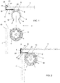
- the group 2, according to the invention, for joining a first plinth 4 to a second plinth 4' of a piece of furniture or the like comprises two elements, 6 and 8 respectively, to be both associated with one of the two plinths to be joined.
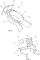
- the first element 6 comprises a plate 10, which is provided on a face (the front one) with connection means 12 to the foot 14 provided at the corner of the piece of furniture.
- connection means 12 comprise a fork hook configured to engage the leg of the foot 4 in removable manner.
- such fork hook comprises elastic wings 16 which surround and embrace the leg of the foot 14.
- the elastic wings 16 are shaped so as to mutually define a first zone, intended to engage the upper leg of such foot, and a second flared zone, adapted to promote said engagement.
- the plate 10 is provided with a hammer-shaped protrusion 18 which is intended to be inserted in a channel (not shown) which is counter-shaped with respect to said protrusion and which is obtained longitudinally on the plinths 4.
- the connection between the first element 6 and the plinth 4 occurs in traditional manner by inserting the protrusion 18 in the channel so that the outermost hammer-shaped part of the latter is parallel in the development direction of the channel itself.
- the first element 6 is turned by 90° so that the undercut hammer-shaped portions of the protrusion 18 abut on corresponding counter-shaped edges of the channel, thus preventing the first element 6 of the plinth 4 from being pulled out.
- the plate 10 also comprises a lateral extension 20 which is provided at its rear face (i.e. the one facing the plinth) with first means 22 which are intended to cooperate with corresponding second means 24 obtained in the second element 8, as will appear clearer below in order to contrast the relative sliding of said first element 6 with respect to said second element 8.
- the first cooperation means 22 comprises a plurality of recessed semi-circular ribs 23, which are vertical and parallel to one another.
- the lateral extension 20 is slightly frontally offset with respect to the remaining part of the body of the plate 10 so that once the first element 6 is connected to the plinth 4, the lateral extension 20 delimits a loop with the plinth itself for inserting a corresponding terminal stretch 33 of the second element 8.
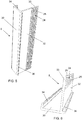
- the second element 8 comprises a substantially "L"-shaped section bar, i.e. with two portions 30 and 32, preferably not equal, substantially orthogonal to one another.
- the free longitudinal edge of the first portion 30 of the section bar i.e. the smaller one, is folded so as to define a wing 34, which is substantially parallel to the second portion 32, i.e. the greater one, of the section bar itself. Furthermore, the other edge of the first portion 30 extends beyond the second portion 32, thus defining a longitudinal shoulder 36 which is orthogonal to it.
- section bar which defines the second element 8 is dimensioned so that the distance between the facing surfaces of the folded wing 34 and of the second portion 32 substantially corresponds to the thickness of the end 40 of the plinth 4.
- the second portion 32 On the side of the longitudinal shoulder 36 and at its end zone 33, the second portion 32 is concerned by the second means 24, which are intended to cooperate with the first means 22 of the first element 6.
- these second cooperation means 24 comprise a plurality of protruding semi-circular ribs 25, vertical and parallel to one another.
- the first means 22 of the first element 6 have a surface profile which is complementary to that of the second means 24 of the second element 8.
- the first means 22 and the second means 24, obtained in the first element 6 and in the second element 8, respectively, are configured so as to increase the friction resulting from the contact and/or the sliding of the first element 6 towards the second element 8.
- the end stretch 33 may be offset with respect to the remaining part of the second portion 32 of the second element 8 so that, once the latter is associated with the plinth 4, the end stretch 33 delimits a loop with the plinth itself for inserting the side extension 20 which, in this case, is coplanar with the remaining part of the body of the plate 10.
- the other plinth 4' intended to define the joint may be associated with/constrained to the foot 14 of the piece of furniture by means of a device 5 which has the same construction features of the first element 6 of the group 2, or by means of any traditional latching device.
- first means 22 which are intended to cooperate with corresponding second means 24 obtained in the second element 8 in order to contrast the relative sliding of said first element 6 with respect to said second element 8 may comprise other traditional types of interaction and/or mechanical coupling between two elements, such as for example means and counter-means for achieving a coupling by latching, or by fitting (e.g. of the male-female type), or by restraining, by interference, by even partial shape coupling etc.
- the first element 6 is applied to the plinth 4 by appropriately inserting the hammer-shaped protrusion 18 in the longitudinal channel obtained in the plinth itself. Successively, the first element 6 is made to slide along the channel of the plinth 4 so as to distance it from the end 40 of the latter enough to allow the application of the second element 8.
- the second element 8 is applied onto the end 40 of the plinth 4 so that its head edge 42 abuts frontally on the base of the first position 30, while it is retained laterally between the folded wing 34 and the second portion 32.
- the first element 6 is made to slide towards the end of the plinth 40, and then towards the second element 8, until the lateral protrusion 20 of the first element 6 comes into contact with the end stretch 33 of the second portion 32 of the second element 8.
- the first cooperation means 22 and the second cooperation means 24 mutually interact by adjusting the positioning of the first element 6 on the second element 8 and locking any involuntary sliding of the first element 6 away from the second element 8.
- first cooperation means 22 and the second cooperation means 24 are constituted by vertical ribs which are respectively recessed and protruding, or vice versa, makes it possible to adjust the sliding of the first element 6 on the second element 8 in successive steps.
- the first element 6 is made to slide towards the second element 8 on the plinth 4 until the latching means 12 of the first element are in position facing or aligned with a foot 14 which was already previously constrained to the other plinth 4' to be joined.
- the plinth 4 thus arranged is approached to the feet 14 and, by applying an appropriate pressure, the elastic wings 16 of the latching means 12 are elastically deformed to allow them to embrace the foot 14.
- the head edge 43 of the plinth 4' arrives to rest frontally on the second portion of the second element 8 while its outer edge 45 rests on the shoulder 36 of the second element itself.
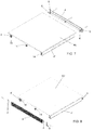
- the first element 6 is provided on its front face with an appendix 50 that develops at the lateral extension 20.
- the group of elements 2 according to the invention also comprises a third element 60 to be inserted/applied at the other plinth 4' to be joined.
- the third element 60 comprises two orthogonal faces 62, 64 between which a profile 66 develops internally which is complementary at least in part and thus rests on the cylindrical portion of the leg of the foot 14.
- a hammer-shaped protrusion (not shown) is provided at a first face 62 of the third element 60 with constructive and functional features similar to those described above related to the first element 6.
- a plurality of parallel ribs 68 are provided, preferably with enlarged head 70, at the other face 64 of the third element 60 between which the appendix 50 of the first element 6 can be inserted by elastic deformation.
- the appendix has a convex head 52 of width greater than the distance between the enlarged heads 70 of two continuous ribs 68.
- the embodiment of fig. 12 substantially corresponds to that of fig. 11 except in that the first element 6 comprises two protruding appendixes 50, one at a lateral extension 20 and one at the base body of the plate 10 of the first element 10. Furthermore, the face of the third element 60 is provided with ribs 68 has a greater development in order to allow both appendixes 50 of the first element 6 to be inserted within two distinct pairs of mutually adjacent ribs 68. Appropriately, the complementary profile 66 is shaped so as to embrace/envelop nearly half of the cylindrical surface of the leg of the foot 14.
- the group of elements 2 according to the invention is particularly advantageous with respect to traditional ones, because:
- the present invention differs from JP S63 189029 because the latter neither describes nor suggests any type of cooperation or above all any type of contact between the first element (i.e. the one which latches the foot) and the second element (i.e. the angular section bar in which the two plinths to be joined abut frontally).
Landscapes
- Furniture Connections (AREA)
- Connection Of Plates (AREA)
- Assembled Shelves (AREA)
Applications Claiming Priority (1)
| Application Number | Priority Date | Filing Date | Title |
|---|---|---|---|
| IT102016000126356A IT201600126356A1 (it) | 2016-12-14 | 2016-12-14 | Complesso di elementi perfezionato per la giunzione degli zoccoli di un mobile o simile. |
Publications (1)
| Publication Number | Publication Date |
|---|---|
| EP3335595A1 true EP3335595A1 (fr) | 2018-06-20 |
Family
ID=58455534
Family Applications (1)
| Application Number | Title | Priority Date | Filing Date |
|---|---|---|---|
| EP17206889.2A Withdrawn EP3335595A1 (fr) | 2016-12-14 | 2017-12-13 | Groupe d'éléments améliorés permettant d'assembler les plinthes d'un meuble ou similaire |
Country Status (2)
| Country | Link |
|---|---|
| EP (1) | EP3335595A1 (fr) |
| IT (1) | IT201600126356A1 (fr) |
Cited By (3)
| Publication number | Priority date | Publication date | Assignee | Title |
|---|---|---|---|---|
| EP3903638A1 (fr) * | 2020-04-30 | 2021-11-03 | Volpato Industrie S.p.A. | Set d'éléments perfectionnés pour assembler une plinthe au pied d'un meuble ou similaire |
| IT202000022456A1 (it) * | 2020-09-23 | 2022-03-23 | Volpato Ind S P A | Complesso di elementi perfezionato per la giunzione di uno zoccolo al piedino di un mobile o simile |
| EP4762995A1 (fr) * | 2024-12-20 | 2026-06-24 | Volpato Industrie S.p.A. | Système amélioré pour assembler des plinthes au pied d'un meuble ou similaire |
Citations (3)
| Publication number | Priority date | Publication date | Assignee | Title |
|---|---|---|---|---|
| JPS63189029A (ja) | 1987-02-02 | 1988-08-04 | Nec Corp | タイミング抽出回路 |
| JPS63189029U (fr) * | 1987-05-29 | 1988-12-05 | ||
| EP1362530A1 (fr) * | 2002-05-17 | 2003-11-19 | SCILM S.p.A. | Dispositif pour coupler la plinthe d'une pièce de mobilier au pied de cette pièce de mobilier |
-
2016
- 2016-12-14 IT IT102016000126356A patent/IT201600126356A1/it unknown
-
2017
- 2017-12-13 EP EP17206889.2A patent/EP3335595A1/fr not_active Withdrawn
Patent Citations (3)
| Publication number | Priority date | Publication date | Assignee | Title |
|---|---|---|---|---|
| JPS63189029A (ja) | 1987-02-02 | 1988-08-04 | Nec Corp | タイミング抽出回路 |
| JPS63189029U (fr) * | 1987-05-29 | 1988-12-05 | ||
| EP1362530A1 (fr) * | 2002-05-17 | 2003-11-19 | SCILM S.p.A. | Dispositif pour coupler la plinthe d'une pièce de mobilier au pied de cette pièce de mobilier |
Cited By (3)
| Publication number | Priority date | Publication date | Assignee | Title |
|---|---|---|---|---|
| EP3903638A1 (fr) * | 2020-04-30 | 2021-11-03 | Volpato Industrie S.p.A. | Set d'éléments perfectionnés pour assembler une plinthe au pied d'un meuble ou similaire |
| IT202000022456A1 (it) * | 2020-09-23 | 2022-03-23 | Volpato Ind S P A | Complesso di elementi perfezionato per la giunzione di uno zoccolo al piedino di un mobile o simile |
| EP4762995A1 (fr) * | 2024-12-20 | 2026-06-24 | Volpato Industrie S.p.A. | Système amélioré pour assembler des plinthes au pied d'un meuble ou similaire |
Also Published As
| Publication number | Publication date |
|---|---|
| IT201600126356A1 (it) | 2018-06-14 |
Similar Documents
| Publication | Publication Date | Title |
|---|---|---|
| US10441074B2 (en) | Shelf frame assembly system | |
| US5970675A (en) | Modular panel assembly | |
| US10376053B2 (en) | Drawer | |
| KR20170002540A (ko) | 빌딩 패널용 기계적 잠금 시스템 | |
| US20210164235A1 (en) | Step clip fastening system and method | |
| KR100921262B1 (ko) | 조립식 가구 | |
| EP2241216A1 (fr) | Système d'assemblage pour connecter les éléments de mobilier | |
| EP2881010A1 (fr) | Système de fixation pour meubles | |
| US12193588B1 (en) | Fast fit bracket | |
| WO2012065209A1 (fr) | Organe d'assemblage pour mobilier modulaire | |
| US20180073255A1 (en) | Cabinet with snap-in frame | |
| EP0487127A1 (fr) | Construction de cloison, avec éléments de cloison fixés aux éléments d'ossature ou moyen d'accouplements cachés | |
| CN103620240B (zh) | 连接元件 | |
| EP2886012B1 (fr) | Systeme de fixation pour des meubles | |
| CN107529888A (zh) | 用于家具的组装式抽屉和用于组装该抽屉的方法 | |
| US20170311716A1 (en) | Cabinet assembly | |
| US20050084323A1 (en) | Securing device for rear walls of cabinet furniture | |
| US10617205B2 (en) | Systems for quick mounting applied to a cabinet body | |
| WO2020027667A1 (fr) | Composants de meuble améliorés et ensembles associés | |
| CA2205164C (fr) | Cadre de porte | |
| GB2534002A (en) | A frame | |
| IT201600126356A1 (it) | Complesso di elementi perfezionato per la giunzione degli zoccoli di un mobile o simile. | |
| EP3317467A1 (fr) | Raccord pour cadres de construction structurels | |
| EP1647650A2 (fr) | Plinthe | |
| CN113226119B (zh) | 具有锁定系统的搁架和用于将搁架锁定至家具用品的方法 |
Legal Events
| Date | Code | Title | Description |
|---|---|---|---|
| PUAI | Public reference made under article 153(3) epc to a published international application that has entered the european phase |
Free format text: ORIGINAL CODE: 0009012 |
|
| AK | Designated contracting states |
Kind code of ref document: A1 Designated state(s): AL AT BE BG CH CY CZ DE DK EE ES FI FR GB GR HR HU IE IS IT LI LT LU LV MC MK MT NL NO PL PT RO RS SE SI SK SM TR |
|
| AX | Request for extension of the european patent |
Extension state: BA ME |
|
| STAA | Information on the status of an ep patent application or granted ep patent |
Free format text: STATUS: THE APPLICATION IS DEEMED TO BE WITHDRAWN |
|
| 18D | Application deemed to be withdrawn |
Effective date: 20181221 |