EP3336201B1 - Klebemaschine - Google Patents
Klebemaschine Download PDFInfo
- Publication number
- EP3336201B1 EP3336201B1 EP17207135.9A EP17207135A EP3336201B1 EP 3336201 B1 EP3336201 B1 EP 3336201B1 EP 17207135 A EP17207135 A EP 17207135A EP 3336201 B1 EP3336201 B1 EP 3336201B1
- Authority
- EP
- European Patent Office
- Prior art keywords
- conveyor belt
- machine
- projector
- extreme
- gluing
- Prior art date
- Legal status (The legal status is an assumption and is not a legal conclusion. Google has not performed a legal analysis and makes no representation as to the accuracy of the status listed.)
- Not-in-force
Links
- 238000004026 adhesive bonding Methods 0.000 title claims description 34
- 239000010985 leather Substances 0.000 claims description 32
- 239000000463 material Substances 0.000 claims description 9
- 230000010355 oscillation Effects 0.000 claims description 6
- 239000007787 solid Substances 0.000 claims description 3
- 239000011111 cardboard Substances 0.000 claims description 2
- 239000004744 fabric Substances 0.000 claims description 2
- 238000011144 upstream manufacturing Methods 0.000 claims description 2
- 239000003292 glue Substances 0.000 description 19
- 230000003534 oscillatory effect Effects 0.000 description 10
- 239000011248 coating agent Substances 0.000 description 3
- 238000000576 coating method Methods 0.000 description 3
- 238000004519 manufacturing process Methods 0.000 description 3
- 239000002699 waste material Substances 0.000 description 3
- 239000000853 adhesive Substances 0.000 description 1
- 230000001070 adhesive effect Effects 0.000 description 1
- 238000003754 machining Methods 0.000 description 1
- 238000000034 method Methods 0.000 description 1
- 230000000007 visual effect Effects 0.000 description 1
Images


Classifications
-
- C—CHEMISTRY; METALLURGY
- C14—SKINS; HIDES; PELTS; LEATHER
- C14B—MECHANICAL TREATMENT OR PROCESSING OF SKINS, HIDES OR LEATHER IN GENERAL; PELT-SHEARING MACHINES; INTESTINE-SPLITTING MACHINES
- C14B7/00—Special leathers and their manufacture
- C14B7/02—Composite leathers
-
- B—PERFORMING OPERATIONS; TRANSPORTING
- B05—SPRAYING OR ATOMISING IN GENERAL; APPLYING FLUENT MATERIALS TO SURFACES, IN GENERAL
- B05C—APPARATUS FOR APPLYING FLUENT MATERIALS TO SURFACES, IN GENERAL
- B05C5/00—Apparatus in which liquid or other fluent material is projected, poured or allowed to flow on to the surface of the work
- B05C5/02—Apparatus in which liquid or other fluent material is projected, poured or allowed to flow on to the surface of the work the liquid or other fluent material being discharged through an outlet orifice by pressure, e.g. from an outlet device in contact or almost in contact, with the work
- B05C5/0245—Apparatus in which liquid or other fluent material is projected, poured or allowed to flow on to the surface of the work the liquid or other fluent material being discharged through an outlet orifice by pressure, e.g. from an outlet device in contact or almost in contact, with the work for applying liquid or other fluent material to a moving work of indefinite length, e.g. to a moving web
-
- C—CHEMISTRY; METALLURGY
- C14—SKINS; HIDES; PELTS; LEATHER
- C14B—MECHANICAL TREATMENT OR PROCESSING OF SKINS, HIDES OR LEATHER IN GENERAL; PELT-SHEARING MACHINES; INTESTINE-SPLITTING MACHINES
- C14B17/00—Details of apparatus or machines for manufacturing or treating skins, hides, leather, or furs
-
- A—HUMAN NECESSITIES
- A43—FOOTWEAR
- A43D—MACHINES, TOOLS, EQUIPMENT OR METHODS FOR MANUFACTURING OR REPAIRING FOOTWEAR
- A43D25/00—Devices for gluing shoe parts
- A43D25/18—Devices for applying adhesives to shoe parts
- A43D25/183—Devices for applying adhesives to shoe parts by nozzles
-
- B—PERFORMING OPERATIONS; TRANSPORTING
- B05—SPRAYING OR ATOMISING IN GENERAL; APPLYING FLUENT MATERIALS TO SURFACES, IN GENERAL
- B05C—APPARATUS FOR APPLYING FLUENT MATERIALS TO SURFACES, IN GENERAL
- B05C11/00—Component parts, details or accessories not specifically provided for in groups B05C1/00 - B05C9/00
- B05C11/10—Storage, supply or control of liquid or other fluent material; Recovery of excess liquid or other fluent material
Definitions
- the present invention relates to a gluing machine.
- the present invention finds particular use in the processing of leather or imitation leather, fabric, cardboard and various materials in sheet form for the production of leather goods and the like.
- Gluing machines are used to cover, with specific glues for the material, the base elements in leather or imitation leather which are then used to make leather goods and the like, such as belts, diaries, bags, wallets, key rings or otherwise.
- a gluing machine is used to evenly coat these elements or to coat specific sections.
- gluing machines are loaded by an operator, who places the material elements to be glued, generically defined strips of material, on a conveyor belt of a single machine, which brings the strips in succession towards a gluing station where there is a glue dispenser.
- the glue dispenser preferably a gun with nozzle, is positioned above the conveyor belt and moves along a path transversal to the feed direction of the elements to be glued, dispensing the amount of glue needed on the surface of the pieces.
- the conveyor belt has an intermittent progress to allow the coating with glue by the dispenser.
- the conveyor belt moves continuously at a speed sufficient to allow an optimal dispensing of the adhesive on the surface of the pieces.
- the dispenser performs a stroke longer than the length of the elements to be glued, sometimes even equivalent to the width of the conveyor belt.
- the machine is, in fact, used to glue different types of elements for the production of various leather goods or the like, which may thus be different sizes from each other, without however always being able to set the stroke of the dispenser.
- the operator must be properly trained. In particular he/she must know the right distance between the strips, the size of the same, to adjust wherever possible the stroke of the dispenser, and of course he/she must place the strips so that they are perfectly aligned with each other to allow the dispenser to coat them evenly.
- the purpose of the present invention is to provide a gluing machine which makes it possible to overcome the drawbacks of the prior art.
- the purpose of the present invention is to provide a gluing machine that allows even an untrained or not particularly expert operator to place correctly the elements to be glued on the conveyor belt and to configure the machine accordingly.
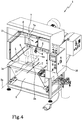
- reference numeral 1 globally denotes a gluing machine, for simplicity hereinafter referred to as the machine 1.
- machine 1 The elements in common to the various embodiments shown in the attached drawings have been indicated with the same reference numeral.
- Figure 1 shows a machine 1 for coating a plurality of elements or strips 2, preferably in leather or imitation leather, with glue.
- the machine 1 comprises a feeding station 1a, at which the elements in leather or imitation leather 2 to be glued are loaded onto a conveyor belt 3, and a gluing station 1b of the leather or imitation leather elements 2.
- the machine 1 further comprises the aforementioned conveyor belt 3, which is configured to transport the elements in leather or imitation leather 2 in a feed direction "T", between the feeding station 1a and the gluing station 1b.
- the conveyor belt 3 moves along the feed direction "T" with an intermittent movement.
- a continuous movement may be provided.
- the leather or imitation leather elements 2 are aligned with each other on the conveyor belt 3, along a machining line "L”, transverse, preferably perpendicular, to the feed direction "T".
- the machine 1 comprises a dispenser 4 of glue placed above the conveyor belt 3 at the gluing station 1b.
- the dispenser 4 is configured to move along a stroke 5 transversal, preferably perpendicular, to the feed direction "T" of the conveyor belt 3, to dispense the glue on a top surface 2a of each leather or imitation leather elements.
- the dispenser 4 is configured to dispense the glue on a gluing area 4a when the leather or imitation leather elements 2 pass through the gluing station 1b.
- the machine 1 further comprises at least one alignment device 7 of the leather or imitation leather elements 2. Said alignment device 7 is adapted to identify a positioning area 2a of the leather or imitation leather elements 2 on the conveyor belt 3 having an extension equal to the effective gluing area 4a.
- the alignment device 7 identifies reference points, which will be used later by the operator to arrange and manually align in the correct position on the conveyor belt 3, the leather or imitation leather elements 2 to be glued.
- the alignment device 7 comprises a projector 7a adapted to project a beam of light 8 on the conveyor belt 3 to identify the positioning area 2a.
- the projector 7a is positioned upstream of the dispenser 4, in a raised position with respect to the conveyor belt 3, so as to project the beam of light 8 at said feeding station 1a.
- a support crossbeam 6 may be provided bearing the projector 7a by means of a projector 7a flange 6a.
- the projector 7a is preferably mobile and can rotate about an axis of rotation X parallel to the feed direction "T" of the conveyor belt 3.
- the projector 7a performs, about the axis of rotation X, a limited oscillation within an angular stroke preferably of 90°.
- the axis of rotation "X" is transverse, preferably perpendicular, to a lying plane “P" of the projector 7a.
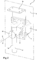
- the machine 1 comprises then an engine 9, configured to impart a rotary, more precisely oscillatory motion "R" to the projector 7a; engine 9 and projector 7a are connected with a first support flange 11 of the motor 9 and a second support flange 12 of the projector 7a.
- the second flange 12 comprises a limiting pin 13.
- the limiting pin 13 is inside the second flange 12 and is configured to limit the oscillatory movement "R" of the projector 7a.
- the limiting pin 13 of the projector 7a is configured to limit the oscillatory movement "R" within an angular stroke. Even more preferably the angular stroke is 90°, so that the oscillatory movement "R” is an oscillation angle limited within the angular stroke of 90°.
- the projector 7a is a LASER pointer or a LED pointer 10. According to a first embodiment shown in Figures 1 and 3 , the projector 7a is configured to project the beam of light 8 in the form of a line 14.
- the line 14 is projected alternately onto the conveyor belt 3 at the first 15a and the second 15b extreme.
- the line 14 is projected onto the conveyor belt 3 when the projector reaches the first 15a or second 15b extreme within the angular stroke.
- the line 14 is not projected during the oscillatory movement "R" between the first 15a or second 15b extreme.
- the machine 1 further comprises a control unit 16, as shown in Figure 1 .
- the control unit 16 controls both the dispenser 4 and the projector 7a.
- the control unit 16 is adapted to configure the oscillatory movement "R" of the projector 7a, making it possible to adjust the angular stroke to define the first extreme 15a and the second extreme 15b and accordingly set the stroke 5 of the dispenser 4.
- the embodiment of Figure 3 shows a machine 1 comprising two projectors 7 positioned above the conveyor belt 3.
- the projectors 7 of this embodiment are placed on opposite sides with respect to the central axis 3a of the conveyor belt 3 oriented along the feed direction "T" and are configured to project the line 14 in the first extreme 15a and in the second extreme 15b.
- Both projectors 7a and 7b have an engine 9 but in this case the oscillatory movement "R" sets out to position the projectors 7 so as to have the extremes 15a and 15b in positions not necessarily symmetrical to each other in relation to the centre of the conveyor belt 3.
- the engine 9 does not operate continuously as in the previous embodiment, but only and solely to position the extremes 15a and 15b during the control step with the control unit 16.
- the control unit 16 enables the adjustment of both projectors 7a and 7b to define the extremes 15a and 15b, then adjusting the stroke 5 of the dispenser 4.
- the projector 7a projects a beam of light 8 in the form of profiles 17. In this case also it is placed in a raised position and central to the conveyor belt 3.
- the projector 7a thus configured projects on the conveyor belt 3 at the positioning area 2a the beam of light 8 in the form of a specific profile corresponding to a particular geometry of the product to be glued in order to define a precise gluing area 4a.
- the profile 17 that is projected onto the conveyor belt 3 is a solid figure or set of lines configured to reproduce a perimeter of the figure.
- the figure, solid or perimetral, which is projected onto the conveyor belt 3 is such as to match the shape of the element 2 to be placed on the conveyor belt 3 on which to apply the glue, also projecting the piece ID.
- all the embodiments described above identify a visual aid for the operator.
- the operator uses the control unit 16. Based on the size of the elements 2 to be placed on the conveyor belt 3, the operator uses the control unit 16 to set the extremes within which the projector 7a must act. Therefore, the control unit 16 will set the stroke 5 within which the dispenser 4 must act.
- the user may decide to set the stroke 5 of the dispenser 4 thus obtaining the extremes between which to place the strips 2 or positions of the profiles 17 as regards strips 2 of particular shapes.
- the machine 1 described above makes it possible to overcome the drawbacks of the prior art.
- the machine 1 described above can be used by an inexperienced and untrained operator very easily. It also saves time and resources thanks to the shorter set-up time and the glue saved by a more precise stroke 5 of the dispenser 4.
Landscapes
- Engineering & Computer Science (AREA)
- Chemical & Material Sciences (AREA)
- Manufacturing & Machinery (AREA)
- Mechanical Engineering (AREA)
- Organic Chemistry (AREA)
- Composite Materials (AREA)
- Application Of Or Painting With Fluid Materials (AREA)
- Coating Apparatus (AREA)
- Cereal-Derived Products (AREA)
- Saccharide Compounds (AREA)
Claims (9)
- Maschine (1) zum Kleben von Elementen (2), bestehend aus verschiedenen Bahnen aus Material wie Leder oder Lederimitat, Stoff oder Pappe, umfassend:- eine Zuführungsstation (1a) zum Zuführen der zu verklebenden Elemente (2);- eine Klebestation (1b) zum Kleben der Elemente (2);- ein Förderband (3), das ausgelegt ist, um eine Vielzahl dieser Elemente (2) entlang einer Vorschubrichtung (T) zwischen der Zuführungsstation (1a) und der Klebestation (1b) zu transportieren;- eine Ausgabevorrichtung (4) für Klebematerial, die über dem Förderband (3) bewegbar und ausgelegt ist, um das Klebematerial auf einem Klebebereich (4a) zu verteilen, wenn die Elemente (2) durch die Klebestation (1b) geführt werden;- mindestens eine Ausrichtungsvorrichtung (7) für die Elemente (2), die einen Positionierungsbereich (2a) identifiziert und Referenzpunkte für das manuelle Ausrichten der Elemente (2) auf dem Förderband (3) definiert, aufweisend eine Ausdehnung, die größer oder gleich dem Klebebereich (4a) ist, dadurch gekennzeichnet, dass die Ausrichtungsvorrichtung (7) einen Projektor (7a) umfasst, der ausgelegt ist, um einen Lichtstrahl (8) auf das Förderband (3) zu projizieren, um den Positionierungsbereich (2a) zu identifizieren, wobei sich der Projektor (7a) um eine Rotationsachse (X) drehen kann, die parallel zur Vorschubrichtung (T) des Förderbands (3) angeordnet ist, wobei die Rotationsachse (X) eine Schwingbewegung (R) zwischen einem ersten Endpunkt (15a) und einem zweiten Endpunkt (15b) definiert, wodurch es dem Bediener ermöglicht wird, die Position des Elements (2) zwischen dem ersten Endpunkt (15a) und dem zweiten Endpunkt (15b) zu korrigieren, wobei die Maschine eine Steuereinheit (16) für den Projektor (7a) umfasst und die Ausgabevorrichtung (4) ausgelegt ist, um die Bewegung des Projektors (7a) zu steuern, um die Bewegung der Ausgabevorrichtung (4) zu regeln, oder umgekehrt.
- Maschine (1) nach dem vorhergehenden Anspruch, wobei der Projektor (7a) nach der Ausgabevorrichtung (4) in einer angehobenen Position zum Förderband (3) positioniert ist, sodass der Lichtstrahl (8) an der Zuführungsstation (1a) projiziert wird.
- Maschine (1) nach dem vorhergehenden Anspruch, wobei der Projektor (7a) um die Rotationsachse (X) eine begrenzte Schwingung mit einem Winkelhub von vorzugsweise 90° durchführt.
- Maschine (1) nach dem vorhergehenden Anspruch, wobei die Schwingung zwischen einem ersten Endpunkt (15a) und einem zweiten Endpunkt (15b) begrenzt ist, enthalten zwischen dem Winkelhub und übereinstimmend mit den Endpunkten der Elemente (2), wobei die Schwingbewegung zwischen dem ersten Endpunkt (15a) und dem zweiten Endpunkt (15b) alterniert.
- Maschine (1) nach dem vorhergehenden Anspruch, wobei der Projektor (7a) den Lichtstrahl (8) in Form einer Linie (14) projiziert,
wobei die Linie (14) abwechselnd auf das Förderband (3) am ersten (15a) oder zweiten (15b) Endpunkt projiziert wird. - Maschine (1) nach einem oder mehreren der Ansprüche 1 bis 4, wobei der Projektor (7a) den Lichtstrahl (8) in Form von Profilen (17) projiziert.
- Maschine (1) nach dem vorhergehenden Anspruch, wobei ein jedes der Profile (17), die auf das Förderband (3) projiziert werden, eine Festkörperfigur oder ein Satz von Linien ist, ausgelegt, um einen Umfang des Elements (2) zu reproduzieren, auf dem das Klebematerial aufgebracht werden muss.
- Maschine (1) nach einem oder mehreren der vorhergehenden Ansprüche, wobei der Projektor (7a) ein Laserprojektor (10) oder ein LED-Pointer ist.
- Maschine (1) nach einem oder mehreren der vorhergehenden Ansprüche, umfassend zwei oder mehr Projektoren (7a, 7b), die über dem Förderband (3) positioniert sind.
Applications Claiming Priority (1)
| Application Number | Priority Date | Filing Date | Title |
|---|---|---|---|
| IT102016000127036A IT201600127036A1 (it) | 2016-12-15 | 2016-12-15 | Macchina per incollaggio |
Publications (2)
| Publication Number | Publication Date |
|---|---|
| EP3336201A1 EP3336201A1 (de) | 2018-06-20 |
| EP3336201B1 true EP3336201B1 (de) | 2019-07-10 |
Family
ID=58455551
Family Applications (1)
| Application Number | Title | Priority Date | Filing Date |
|---|---|---|---|
| EP17207135.9A Not-in-force EP3336201B1 (de) | 2016-12-15 | 2017-12-13 | Klebemaschine |
Country Status (2)
| Country | Link |
|---|---|
| EP (1) | EP3336201B1 (de) |
| IT (1) | IT201600127036A1 (de) |
Families Citing this family (9)
| Publication number | Priority date | Publication date | Assignee | Title |
|---|---|---|---|---|
| PT115672A (pt) * | 2019-07-26 | 2021-01-26 | Jorge Maciel Lima Ricardo | Equipamento para aplicação de matéria adesiva em estamparia têxtil |
| CN112642665B (zh) * | 2019-10-11 | 2025-04-08 | 律致新能源科技(上海)有限公司 | 燃料电池双极板自动涂胶机 |
| CN110976211A (zh) * | 2019-12-19 | 2020-04-10 | 东莞市南工机械设备科技有限公司 | 工件高精度点胶装置 |
| CN112916259B (zh) * | 2021-01-20 | 2022-04-05 | 睢县中宇马具服装有限公司 | 一种皮雕软包加工设备 |
| CN113019844A (zh) * | 2021-03-18 | 2021-06-25 | 苏州小蜂视觉科技有限公司 | 一种规划点胶轨迹的方法和装置、点胶设备 |
| CN113926654B (zh) * | 2021-11-05 | 2022-09-06 | 浙江企鹅鞋业有限公司 | 一种高效的皮鞋自动涂胶装置及其工作方法 |
| CN114260144A (zh) * | 2021-12-29 | 2022-04-01 | 深圳市兴威格科技有限公司 | 一种防水双面胶的涂胶工艺及其涂胶装置 |
| CN116919057B (zh) * | 2023-08-23 | 2025-10-03 | 晋江市崇丰鞋材有限公司 | 一种抗断裂的橡胶鞋底及其生产方法 |
| CN119405129B (zh) * | 2025-01-08 | 2025-03-21 | 温州市利步达鞋业有限公司 | 一种体能训练鞋复合鞋底内垫层粘合压合设备 |
Family Cites Families (4)
| Publication number | Priority date | Publication date | Assignee | Title |
|---|---|---|---|---|
| DE3915042A1 (de) * | 1989-05-08 | 1990-11-15 | Dokoupil Jiri | Verfahren und einrichtugn zum bearbeiten von weichflexiblen flachmaterialstuecken |
| ITBO940166A1 (it) * | 1994-04-18 | 1995-10-18 | Talamonti Macchine S N C Flli | Metodo per l'applicazione di collane sulla superficie superiore di suole per calzature e dispositivo che attua tale metodo |
| EP1157793A1 (de) * | 2000-05-26 | 2001-11-28 | Thea Felber | Vorrichtung und Verfahren zum Ausrichten eines Zuschnittmusters auf der Oberfläche eines Materials |
| ITBO20070237A1 (it) * | 2007-04-02 | 2008-10-03 | Teseo Spa | Procedimento per ottimizzare l'ottenimento di articoli interessati da loghi |
-
2016
- 2016-12-15 IT IT102016000127036A patent/IT201600127036A1/it unknown
-
2017
- 2017-12-13 EP EP17207135.9A patent/EP3336201B1/de not_active Not-in-force
Non-Patent Citations (1)
| Title |
|---|
| None * |
Also Published As
| Publication number | Publication date |
|---|---|
| EP3336201A1 (de) | 2018-06-20 |
| IT201600127036A1 (it) | 2018-06-15 |
Similar Documents
| Publication | Publication Date | Title |
|---|---|---|
| EP3336201B1 (de) | Klebemaschine | |
| CA3075092C (en) | Container decoration apparatus and method | |
| US20180050499A1 (en) | Vamp 3d-printing system | |
| CN108349287B (zh) | 制书装置 | |
| US20180312288A1 (en) | Sealing device | |
| EP3538443A1 (de) | Etikettiervorrichtung und verfahren zum betrieb solch einer etikettiervorrichtung | |
| JP5588094B2 (ja) | 弁シート材等をチューブ状のピースの各構成要素に対して位置決めする方法および装置 | |
| KR20180063488A (ko) | 코일 포장용 자동 내주링 제조 장치 | |
| US4710256A (en) | Apparatus for attaching flap-over covers to stacks of paper sheets or the like | |
| KR101557675B1 (ko) | 접착제 도포수단 및 이를 이용한 포장용 상자 제조장치 | |
| JP7241083B2 (ja) | ブックブロック綴じのためのシステム及び装置並びにブックブロック綴じの方法 | |
| CN111497349B (zh) | 一种薄料折边机及用于薄料折边机的折边方法 | |
| US12280390B2 (en) | Glue application device | |
| WO2021026815A1 (zh) | 薄膜处理系统以及撕膜装置的撕膜方法 | |
| JP7273737B2 (ja) | 喫煙物品の包装バンドに接着剤を塗布するための方法 | |
| JP5729772B2 (ja) | 高速自動製凾機における圧着痕防止用のブランク間隔制御装置およびその制御方法 | |
| US20080314513A1 (en) | Device for imparting a pattern onto the surface of work pieces | |
| KR101523874B1 (ko) | 인쇄지 접착 장치 | |
| CN205573133U (zh) | 一种制袋机 | |
| KR101629196B1 (ko) | 타이어용 반제품 압연물 시트의 접합장치 | |
| JP7601584B2 (ja) | ラベル貼付装置およびラベル貼付方法 | |
| CN109476433B (zh) | 用于板材元件加工机的具有相机校准系统的质量控制站 | |
| KR101291457B1 (ko) | 다무늬 랩핑시트를 이용한 프레임 및 그 제조방법 | |
| CN116209578A (zh) | 用于膜的表面处理的机器 | |
| JP2025179019A (ja) | 加工機 |
Legal Events
| Date | Code | Title | Description |
|---|---|---|---|
| PUAI | Public reference made under article 153(3) epc to a published international application that has entered the european phase |
Free format text: ORIGINAL CODE: 0009012 |
|
| STAA | Information on the status of an ep patent application or granted ep patent |
Free format text: STATUS: THE APPLICATION HAS BEEN PUBLISHED |
|
| AK | Designated contracting states |
Kind code of ref document: A1 Designated state(s): AL AT BE BG CH CY CZ DE DK EE ES FI FR GB GR HR HU IE IS IT LI LT LU LV MC MK MT NL NO PL PT RO RS SE SI SK SM TR |
|
| AX | Request for extension of the european patent |
Extension state: BA ME |
|
| STAA | Information on the status of an ep patent application or granted ep patent |
Free format text: STATUS: REQUEST FOR EXAMINATION WAS MADE |
|
| 17P | Request for examination filed |
Effective date: 20181205 |
|
| RBV | Designated contracting states (corrected) |
Designated state(s): AL AT BE BG CH CY CZ DE DK EE ES FI FR GB GR HR HU IE IS IT LI LT LU LV MC MK MT NL NO PL PT RO RS SE SI SK SM TR |
|
| GRAP | Despatch of communication of intention to grant a patent |
Free format text: ORIGINAL CODE: EPIDOSNIGR1 |
|
| STAA | Information on the status of an ep patent application or granted ep patent |
Free format text: STATUS: GRANT OF PATENT IS INTENDED |
|
| INTG | Intention to grant announced |
Effective date: 20190205 |
|
| GRAA | (expected) grant |
Free format text: ORIGINAL CODE: 0009210 |
|
| STAA | Information on the status of an ep patent application or granted ep patent |
Free format text: STATUS: THE PATENT HAS BEEN GRANTED |
|
| AK | Designated contracting states |
Kind code of ref document: B1 Designated state(s): AL AT BE BG CH CY CZ DE DK EE ES FI FR GB GR HR HU IE IS IT LI LT LU LV MC MK MT NL NO PL PT RO RS SE SI SK SM TR |
|
| REG | Reference to a national code |
Ref country code: GB Ref legal event code: FG4D |
|
| REG | Reference to a national code |
Ref country code: CH Ref legal event code: EP Ref country code: AT Ref legal event code: REF Ref document number: 1153646 Country of ref document: AT Kind code of ref document: T Effective date: 20190715 |
|
| REG | Reference to a national code |
Ref country code: DE Ref legal event code: R096 Ref document number: 602017005205 Country of ref document: DE |
|
| REG | Reference to a national code |
Ref country code: IE Ref legal event code: FG4D |
|
| REG | Reference to a national code |
Ref country code: NL Ref legal event code: MP Effective date: 20190710 |
|
| REG | Reference to a national code |
Ref country code: LT Ref legal event code: MG4D |
|
| REG | Reference to a national code |
Ref country code: AT Ref legal event code: MK05 Ref document number: 1153646 Country of ref document: AT Kind code of ref document: T Effective date: 20190710 |
|
| PG25 | Lapsed in a contracting state [announced via postgrant information from national office to epo] |
Ref country code: HR Free format text: LAPSE BECAUSE OF FAILURE TO SUBMIT A TRANSLATION OF THE DESCRIPTION OR TO PAY THE FEE WITHIN THE PRESCRIBED TIME-LIMIT Effective date: 20190710 Ref country code: FI Free format text: LAPSE BECAUSE OF FAILURE TO SUBMIT A TRANSLATION OF THE DESCRIPTION OR TO PAY THE FEE WITHIN THE PRESCRIBED TIME-LIMIT Effective date: 20190710 Ref country code: LT Free format text: LAPSE BECAUSE OF FAILURE TO SUBMIT A TRANSLATION OF THE DESCRIPTION OR TO PAY THE FEE WITHIN THE PRESCRIBED TIME-LIMIT Effective date: 20190710 Ref country code: BG Free format text: LAPSE BECAUSE OF FAILURE TO SUBMIT A TRANSLATION OF THE DESCRIPTION OR TO PAY THE FEE WITHIN THE PRESCRIBED TIME-LIMIT Effective date: 20191010 Ref country code: NL Free format text: LAPSE BECAUSE OF FAILURE TO SUBMIT A TRANSLATION OF THE DESCRIPTION OR TO PAY THE FEE WITHIN THE PRESCRIBED TIME-LIMIT Effective date: 20190710 Ref country code: AT Free format text: LAPSE BECAUSE OF FAILURE TO SUBMIT A TRANSLATION OF THE DESCRIPTION OR TO PAY THE FEE WITHIN THE PRESCRIBED TIME-LIMIT Effective date: 20190710 Ref country code: PT Free format text: LAPSE BECAUSE OF FAILURE TO SUBMIT A TRANSLATION OF THE DESCRIPTION OR TO PAY THE FEE WITHIN THE PRESCRIBED TIME-LIMIT Effective date: 20191111 Ref country code: NO Free format text: LAPSE BECAUSE OF FAILURE TO SUBMIT A TRANSLATION OF THE DESCRIPTION OR TO PAY THE FEE WITHIN THE PRESCRIBED TIME-LIMIT Effective date: 20191010 Ref country code: SE Free format text: LAPSE BECAUSE OF FAILURE TO SUBMIT A TRANSLATION OF THE DESCRIPTION OR TO PAY THE FEE WITHIN THE PRESCRIBED TIME-LIMIT Effective date: 20190710 |
|
| PG25 | Lapsed in a contracting state [announced via postgrant information from national office to epo] |
Ref country code: GR Free format text: LAPSE BECAUSE OF FAILURE TO SUBMIT A TRANSLATION OF THE DESCRIPTION OR TO PAY THE FEE WITHIN THE PRESCRIBED TIME-LIMIT Effective date: 20191011 Ref country code: RS Free format text: LAPSE BECAUSE OF FAILURE TO SUBMIT A TRANSLATION OF THE DESCRIPTION OR TO PAY THE FEE WITHIN THE PRESCRIBED TIME-LIMIT Effective date: 20190710 Ref country code: IS Free format text: LAPSE BECAUSE OF FAILURE TO SUBMIT A TRANSLATION OF THE DESCRIPTION OR TO PAY THE FEE WITHIN THE PRESCRIBED TIME-LIMIT Effective date: 20191110 Ref country code: AL Free format text: LAPSE BECAUSE OF FAILURE TO SUBMIT A TRANSLATION OF THE DESCRIPTION OR TO PAY THE FEE WITHIN THE PRESCRIBED TIME-LIMIT Effective date: 20190710 Ref country code: LV Free format text: LAPSE BECAUSE OF FAILURE TO SUBMIT A TRANSLATION OF THE DESCRIPTION OR TO PAY THE FEE WITHIN THE PRESCRIBED TIME-LIMIT Effective date: 20190710 Ref country code: ES Free format text: LAPSE BECAUSE OF FAILURE TO SUBMIT A TRANSLATION OF THE DESCRIPTION OR TO PAY THE FEE WITHIN THE PRESCRIBED TIME-LIMIT Effective date: 20190710 |
|
| PG25 | Lapsed in a contracting state [announced via postgrant information from national office to epo] |
Ref country code: TR Free format text: LAPSE BECAUSE OF FAILURE TO SUBMIT A TRANSLATION OF THE DESCRIPTION OR TO PAY THE FEE WITHIN THE PRESCRIBED TIME-LIMIT Effective date: 20190710 |
|
| PG25 | Lapsed in a contracting state [announced via postgrant information from national office to epo] |
Ref country code: DK Free format text: LAPSE BECAUSE OF FAILURE TO SUBMIT A TRANSLATION OF THE DESCRIPTION OR TO PAY THE FEE WITHIN THE PRESCRIBED TIME-LIMIT Effective date: 20190710 Ref country code: PL Free format text: LAPSE BECAUSE OF FAILURE TO SUBMIT A TRANSLATION OF THE DESCRIPTION OR TO PAY THE FEE WITHIN THE PRESCRIBED TIME-LIMIT Effective date: 20190710 Ref country code: EE Free format text: LAPSE BECAUSE OF FAILURE TO SUBMIT A TRANSLATION OF THE DESCRIPTION OR TO PAY THE FEE WITHIN THE PRESCRIBED TIME-LIMIT Effective date: 20190710 Ref country code: IT Free format text: LAPSE BECAUSE OF FAILURE TO SUBMIT A TRANSLATION OF THE DESCRIPTION OR TO PAY THE FEE WITHIN THE PRESCRIBED TIME-LIMIT Effective date: 20190710 Ref country code: RO Free format text: LAPSE BECAUSE OF FAILURE TO SUBMIT A TRANSLATION OF THE DESCRIPTION OR TO PAY THE FEE WITHIN THE PRESCRIBED TIME-LIMIT Effective date: 20190710 |
|
| PG25 | Lapsed in a contracting state [announced via postgrant information from national office to epo] |
Ref country code: SM Free format text: LAPSE BECAUSE OF FAILURE TO SUBMIT A TRANSLATION OF THE DESCRIPTION OR TO PAY THE FEE WITHIN THE PRESCRIBED TIME-LIMIT Effective date: 20190710 Ref country code: SK Free format text: LAPSE BECAUSE OF FAILURE TO SUBMIT A TRANSLATION OF THE DESCRIPTION OR TO PAY THE FEE WITHIN THE PRESCRIBED TIME-LIMIT Effective date: 20190710 Ref country code: CZ Free format text: LAPSE BECAUSE OF FAILURE TO SUBMIT A TRANSLATION OF THE DESCRIPTION OR TO PAY THE FEE WITHIN THE PRESCRIBED TIME-LIMIT Effective date: 20190710 Ref country code: IS Free format text: LAPSE BECAUSE OF FAILURE TO SUBMIT A TRANSLATION OF THE DESCRIPTION OR TO PAY THE FEE WITHIN THE PRESCRIBED TIME-LIMIT Effective date: 20200224 |
|
| REG | Reference to a national code |
Ref country code: DE Ref legal event code: R097 Ref document number: 602017005205 Country of ref document: DE |
|
| REG | Reference to a national code |
Ref country code: DE Ref legal event code: R119 Ref document number: 602017005205 Country of ref document: DE |
|
| PLBE | No opposition filed within time limit |
Free format text: ORIGINAL CODE: 0009261 |
|
| STAA | Information on the status of an ep patent application or granted ep patent |
Free format text: STATUS: NO OPPOSITION FILED WITHIN TIME LIMIT |
|
| PG2D | Information on lapse in contracting state deleted |
Ref country code: IS |
|
| 26N | No opposition filed |
Effective date: 20200603 |
|
| REG | Reference to a national code |
Ref country code: BE Ref legal event code: MM Effective date: 20191231 |
|
| PG25 | Lapsed in a contracting state [announced via postgrant information from national office to epo] |
Ref country code: SI Free format text: LAPSE BECAUSE OF FAILURE TO SUBMIT A TRANSLATION OF THE DESCRIPTION OR TO PAY THE FEE WITHIN THE PRESCRIBED TIME-LIMIT Effective date: 20190710 Ref country code: MC Free format text: LAPSE BECAUSE OF FAILURE TO SUBMIT A TRANSLATION OF THE DESCRIPTION OR TO PAY THE FEE WITHIN THE PRESCRIBED TIME-LIMIT Effective date: 20190710 |
|
| PG25 | Lapsed in a contracting state [announced via postgrant information from national office to epo] |
Ref country code: LU Free format text: LAPSE BECAUSE OF NON-PAYMENT OF DUE FEES Effective date: 20191213 Ref country code: IE Free format text: LAPSE BECAUSE OF NON-PAYMENT OF DUE FEES Effective date: 20191213 Ref country code: DE Free format text: LAPSE BECAUSE OF NON-PAYMENT OF DUE FEES Effective date: 20200701 Ref country code: FR Free format text: LAPSE BECAUSE OF NON-PAYMENT OF DUE FEES Effective date: 20191231 |
|
| PG25 | Lapsed in a contracting state [announced via postgrant information from national office to epo] |
Ref country code: BE Free format text: LAPSE BECAUSE OF NON-PAYMENT OF DUE FEES Effective date: 20191231 |
|
| PG25 | Lapsed in a contracting state [announced via postgrant information from national office to epo] |
Ref country code: CY Free format text: LAPSE BECAUSE OF FAILURE TO SUBMIT A TRANSLATION OF THE DESCRIPTION OR TO PAY THE FEE WITHIN THE PRESCRIBED TIME-LIMIT Effective date: 20190710 |
|
| PG25 | Lapsed in a contracting state [announced via postgrant information from national office to epo] |
Ref country code: HU Free format text: LAPSE BECAUSE OF FAILURE TO SUBMIT A TRANSLATION OF THE DESCRIPTION OR TO PAY THE FEE WITHIN THE PRESCRIBED TIME-LIMIT; INVALID AB INITIO Effective date: 20171213 Ref country code: MT Free format text: LAPSE BECAUSE OF FAILURE TO SUBMIT A TRANSLATION OF THE DESCRIPTION OR TO PAY THE FEE WITHIN THE PRESCRIBED TIME-LIMIT Effective date: 20190710 |
|
| REG | Reference to a national code |
Ref country code: CH Ref legal event code: PL |
|
| PG25 | Lapsed in a contracting state [announced via postgrant information from national office to epo] |
Ref country code: CH Free format text: LAPSE BECAUSE OF NON-PAYMENT OF DUE FEES Effective date: 20201231 Ref country code: LI Free format text: LAPSE BECAUSE OF NON-PAYMENT OF DUE FEES Effective date: 20201231 |
|
| PG25 | Lapsed in a contracting state [announced via postgrant information from national office to epo] |
Ref country code: MK Free format text: LAPSE BECAUSE OF FAILURE TO SUBMIT A TRANSLATION OF THE DESCRIPTION OR TO PAY THE FEE WITHIN THE PRESCRIBED TIME-LIMIT Effective date: 20190710 |
|
| GBPC | Gb: european patent ceased through non-payment of renewal fee |
Effective date: 20211213 |
|
| PG25 | Lapsed in a contracting state [announced via postgrant information from national office to epo] |
Ref country code: GB Free format text: LAPSE BECAUSE OF NON-PAYMENT OF DUE FEES Effective date: 20211213 |