EP3336292B1 - Procédé d'actionnement d'une serrure de porte et serrure de porte - Google Patents
Procédé d'actionnement d'une serrure de porte et serrure de porte Download PDFInfo
- Publication number
- EP3336292B1 EP3336292B1 EP16204036.4A EP16204036A EP3336292B1 EP 3336292 B1 EP3336292 B1 EP 3336292B1 EP 16204036 A EP16204036 A EP 16204036A EP 3336292 B1 EP3336292 B1 EP 3336292B1
- Authority
- EP
- European Patent Office
- Prior art keywords
- striker
- door
- locking bar
- door lock
- locked position
- Prior art date
- Legal status (The legal status is an assumption and is not a legal conclusion. Google has not performed a legal analysis and makes no representation as to the accuracy of the status listed.)
- Active
Links
Images


Classifications
-
- E—FIXED CONSTRUCTIONS
- E05—LOCKS; KEYS; WINDOW OR DOOR FITTINGS; SAFES
- E05B—LOCKS; ACCESSORIES THEREFOR; HANDCUFFS
- E05B63/00—Locks or fastenings with special structural characteristics
- E05B63/22—Locks or fastenings with special structural characteristics operated by a pulling or pushing action perpendicular to the front plate, i.e. by pulling or pushing the wing itself
-
- A—HUMAN NECESSITIES
- A47—FURNITURE; DOMESTIC ARTICLES OR APPLIANCES; COFFEE MILLS; SPICE MILLS; SUCTION CLEANERS IN GENERAL
- A47L—DOMESTIC WASHING OR CLEANING; SUCTION CLEANERS IN GENERAL
- A47L15/00—Washing or rinsing machines for crockery or tableware
- A47L15/42—Details
- A47L15/4251—Details of the casing
- A47L15/4257—Details of the loading door
- A47L15/4259—Arrangements of locking or security/safety devices for doors, e.g. door latches, switch to stop operation when door is open
-
- E—FIXED CONSTRUCTIONS
- E05—LOCKS; KEYS; WINDOW OR DOOR FITTINGS; SAFES
- E05B—LOCKS; ACCESSORIES THEREFOR; HANDCUFFS
- E05B15/00—Other details of locks; Parts for engagement by bolts of fastening devices
- E05B15/04—Spring arrangements in locks
-
- E—FIXED CONSTRUCTIONS
- E05—LOCKS; KEYS; WINDOW OR DOOR FITTINGS; SAFES
- E05B—LOCKS; ACCESSORIES THEREFOR; HANDCUFFS
- E05B17/00—Accessories in connection with locks
- E05B17/0025—Devices for forcing the wing firmly against its seat or to initiate the opening of the wing
-
- E—FIXED CONSTRUCTIONS
- E05—LOCKS; KEYS; WINDOW OR DOOR FITTINGS; SAFES
- E05B—LOCKS; ACCESSORIES THEREFOR; HANDCUFFS
- E05B17/00—Accessories in connection with locks
- E05B17/0025—Devices for forcing the wing firmly against its seat or to initiate the opening of the wing
- E05B17/0029—Devices for forcing the wing firmly against its seat or to initiate the opening of the wing motor-operated
-
- E—FIXED CONSTRUCTIONS
- E05—LOCKS; KEYS; WINDOW OR DOOR FITTINGS; SAFES
- E05B—LOCKS; ACCESSORIES THEREFOR; HANDCUFFS
- E05B17/00—Accessories in connection with locks
- E05B17/0025—Devices for forcing the wing firmly against its seat or to initiate the opening of the wing
- E05B17/0033—Devices for forcing the wing firmly against its seat or to initiate the opening of the wing for opening only
- E05B17/0037—Spring-operated
-
- E—FIXED CONSTRUCTIONS
- E05—LOCKS; KEYS; WINDOW OR DOOR FITTINGS; SAFES
- E05B—LOCKS; ACCESSORIES THEREFOR; HANDCUFFS
- E05B47/00—Operating or controlling locks or other fastening devices by electric or magnetic means
- E05B47/0001—Operating or controlling locks or other fastening devices by electric or magnetic means with electric actuators; Constructional features thereof
- E05B47/0002—Operating or controlling locks or other fastening devices by electric or magnetic means with electric actuators; Constructional features thereof with electromagnets
- E05B47/0003—Operating or controlling locks or other fastening devices by electric or magnetic means with electric actuators; Constructional features thereof with electromagnets having a movable core
- E05B47/0004—Operating or controlling locks or other fastening devices by electric or magnetic means with electric actuators; Constructional features thereof with electromagnets having a movable core said core being linearly movable
-
- E—FIXED CONSTRUCTIONS
- E05—LOCKS; KEYS; WINDOW OR DOOR FITTINGS; SAFES
- E05C—BOLTS OR FASTENING DEVICES FOR WINGS, SPECIALLY FOR DOORS OR WINDOWS
- E05C19/00—Other devices specially designed for securing wings, e.g. with suction cups
- E05C19/02—Automatic catches, i.e. released by pull or pressure on the wing
-
- E—FIXED CONSTRUCTIONS
- E05—LOCKS; KEYS; WINDOW OR DOOR FITTINGS; SAFES
- E05C—BOLTS OR FASTENING DEVICES FOR WINGS, SPECIALLY FOR DOORS OR WINDOWS
- E05C3/00—Fastening devices with bolts moving pivotally or rotatively
- E05C3/12—Fastening devices with bolts moving pivotally or rotatively with latching action
- E05C3/16—Fastening devices with bolts moving pivotally or rotatively with latching action with operating handle or equivalent member moving otherwise than rigidly with the latch
- E05C3/22—Fastening devices with bolts moving pivotally or rotatively with latching action with operating handle or equivalent member moving otherwise than rigidly with the latch the bolt being spring controlled
-
- E—FIXED CONSTRUCTIONS
- E05—LOCKS; KEYS; WINDOW OR DOOR FITTINGS; SAFES
- E05B—LOCKS; ACCESSORIES THEREFOR; HANDCUFFS
- E05B53/00—Operation or control of locks by mechanical transmissions, e.g. from a distance
- E05B53/006—Operation or control of locks by mechanical transmissions, e.g. from a distance of ball-train type
-
- E—FIXED CONSTRUCTIONS
- E05—LOCKS; KEYS; WINDOW OR DOOR FITTINGS; SAFES
- E05C—BOLTS OR FASTENING DEVICES FOR WINGS, SPECIALLY FOR DOORS OR WINDOWS
- E05C5/00—Fastening devices with bolts moving otherwise than only rectilinearly and only pivotally or rotatively
- E05C2005/005—Pivoting bolts or catches being able to move in an additional direction, e.g. by sliding or by pivoting about an additional axis, in order to allow closing of the wing even if the bolt or catch is in its locked position
-
- E—FIXED CONSTRUCTIONS
- E05—LOCKS; KEYS; WINDOW OR DOOR FITTINGS; SAFES
- E05Y—INDEXING SCHEME ASSOCIATED WITH SUBCLASSES E05D AND E05F, RELATING TO CONSTRUCTION ELEMENTS, ELECTRIC CONTROL, POWER SUPPLY, POWER SIGNAL OR TRANSMISSION, USER INTERFACES, MOUNTING OR COUPLING, DETAILS, ACCESSORIES, AUXILIARY OPERATIONS NOT OTHERWISE PROVIDED FOR, APPLICATION THEREOF
- E05Y2900/00—Application of doors, windows, wings or fittings thereof
- E05Y2900/30—Application of doors, windows, wings or fittings thereof for domestic appliances
- E05Y2900/304—Application of doors, windows, wings or fittings thereof for domestic appliances for dishwashers
-
- Y—GENERAL TAGGING OF NEW TECHNOLOGICAL DEVELOPMENTS; GENERAL TAGGING OF CROSS-SECTIONAL TECHNOLOGIES SPANNING OVER SEVERAL SECTIONS OF THE IPC; TECHNICAL SUBJECTS COVERED BY FORMER USPC CROSS-REFERENCE ART COLLECTIONS [XRACs] AND DIGESTS
- Y10—TECHNICAL SUBJECTS COVERED BY FORMER USPC
- Y10S—TECHNICAL SUBJECTS COVERED BY FORMER USPC CROSS-REFERENCE ART COLLECTIONS [XRACs] AND DIGESTS
- Y10S292/00—Closure fasteners
- Y10S292/69—Washing machine or stove closure latch
-
- Y—GENERAL TAGGING OF NEW TECHNOLOGICAL DEVELOPMENTS; GENERAL TAGGING OF CROSS-SECTIONAL TECHNOLOGIES SPANNING OVER SEVERAL SECTIONS OF THE IPC; TECHNICAL SUBJECTS COVERED BY FORMER USPC CROSS-REFERENCE ART COLLECTIONS [XRACs] AND DIGESTS
- Y10—TECHNICAL SUBJECTS COVERED BY FORMER USPC
- Y10T—TECHNICAL SUBJECTS COVERED BY FORMER US CLASSIFICATION
- Y10T292/00—Closure fasteners
- Y10T292/08—Bolts
- Y10T292/1043—Swinging
- Y10T292/1051—Spring projected
- Y10T292/1052—Operating means
- Y10T292/1057—Flexible
Definitions
- the present invention relates to a method for actuating a door lock with a lock mechanism in a door lock housing for a door of an electrical household appliance, preferably a dishwasher, in which a bolt is moved by a spring element for locking from an open position to a locked position, the door being in the open position opened and the bolt is disengaged from a latch of a striker arranged on the household appliance and the door is closed in the locking position, the striker is in a locking position in the door lock housing and the bolt is engaged with the latch, starting to lock the door is brought from the open position of the bolt under tension of the spring element into the locking position, in which a closing force acting on the bolt is determined by the spring element, and for unlocking the door of the bolt by a spring not Relatively applied actuating force is brought from the locking position into an unlocking position and, after the locking bracket has been moved away from the locking position, the bolt is moved into the open position by means of the force of the spring element.
- the invention also relates to a door lock for an electrical household appliance for carrying out the method with a door lock housing which can be arranged in the door of the household appliance and has an opening for an opening which can be fastened to the household appliance Striker, a bolt arranged in the door lock housing for engaging a latch in the striker in a locking position, in which the striker is in a locking position, the bolt having a contact surface and being connected to a lever element rotatably mounted about an axis, and one Spring element, is arranged between the lever element and an abutment, wherein in an open position in which the door is unlocked, the spring element is relaxed with respect to a closing force to be applied, and the lever element holds the bolt in a striker area, which in the locking position is occupied by the striker becomes.
- the door lock In the case of electrical household appliances in the manner of a dishwasher, the door lock can be installed both in the door and in the housing of the appliance. On the other of these two parts there is a striker that is inserted into the lock when the door is closed and hooks into it.
- the present invention relates to the cases where the door lock is placed in the door.
- the fronts of the household appliances can have a handle for opening the door in the tried-and-tested manner or, in the case of handle-less fronts, can be opened by appropriate adjusting mechanisms which are triggered either automatically by the machine or by the operator.
- the closing spring is usually tensioned when the door is opened, in order to build up the closing force for the closed state.
- a door lock of the type described in the opening paragraph is known in which the closing spring is tensioned when the door lock is in an open position.
- the door lock has a frame with an opening for a striker and a locking member, such as a locking lever, in the frame.
- a closing spring which is arranged between the closing member and an abutment in the frame, is provided, the closing member being connected to a gripping device.
- the gripping device has a gripping trap, into which the striker enters can be inserted through the opening of the frame, and which has a contact surface against which the entering striker presses and thereby causes a movement of the gripping device.
- the gripping device is shaped in such a way that it loses contact with the contact point when the hook moves and the closing spring can thereby relax.
- the spring has to be pretensioned by the operator when it is opened.
- the door can only be opened automatically, in particular in the case of handle-free doors, only by means of additional complex devices, for example a motor. This is needed to open the door and to bias the spring. Since a motor is usually too complex, such locking systems rely on the handle to open the door. Regarding dishwashers in particular, manufacturers are required by regulations to allow the door to open automatically after washing to support the drying process. This automatic opening can then also be used for handleless doors.
- the present invention is therefore based on the object of proposing a possibility for actuating a door lock or a door lock for household appliances, in particular for dishwashers, in which the lock mechanism is designed in such a functional manner that it can be unlocked (opened) both manually and automatically and a suitably designed door lock can be easily adapted for doors with or without a handle.
- the bolt is brought into the locking position starting from the open position under tension of the spring element.
- a locking force acts on the bolt which is determined by the spring element.
- the bolt is moved from the locking position into an unlocking position by an actuating force not applied by the spring element and, after the locking bracket has been moved away from the locking position of the bolts, is moved into the open position by means of the force of the spring element.
- the applied operating force can be applied manually by muscle power, for example by pulling on the door or by an active element.
- the locking positions assumed may differ from one another.
- the movement of the bolt from the locked position to the open position can, depending on the type of the actuation, by a single or by multiple movements.
- an actuator of the lock mechanism located at the locking position of the locking bracket is pressed against the locking bracket, so that the locking bracket moves into the locking position by moving the actuator away.
- the spring element is first stretched over the actuator by means of the striker and the bolt is moved from the open position into an intermediate position and then the spring element is partially relaxed and the bolt is retained from the intermediate position while maintaining a residual tension of the spring element which forms the closing force moved into the locking position.
- the door is moved when it is closed, so that the movement of the door lock housing causes the striker to enter the door lock housing.
- the bolt thus moves from the open position first into an intermediate position in which the bolt is not yet in engagement with the striker, and then from the intermediate position into the locking position.
- the spring element which is initially relaxed with regard to the closing force, is fully tensioned in the intermediate position and partially tensioned in the locking position, and thus maintains an adjustable closing force with which the bolt presses on the locking bracket in the case of the locking bracket.
- the bolt For manual unlocking by pulling on the door, the bolt is preferably moved from the locking position into a first unlocking position by a relative movement of the striker relative to the bolt against the closing force of the spring element.
- the bolt is expediently moved into a second unlocking position, the actuating force being applied by an electrical active element.
- the unlocking positions for the different types of opening are therefore different.
- the bolt is by the spring force of the Spring element brought back into the open position, regardless of the unlocking position in which the bolt is.
- the actuator is moved back to its starting position when or after leaving the locking position by the striker. This movement can be brought about by supporting the spring element via the lever element and the inherent force of the actuator or solely by the inherent force of the actuator.
- the door lock according to the invention is characterized in that in the open position, in which the door is unlocked, the spring element is relaxed with respect to a closing force to be applied and the lever element holds the bolt in a striker area which is taken up by the striker in the locking position.
- the bolt is therefore essentially in an area which it also occupies in the locking position in which it is arranged in the latch in the striker. In order to get into the locking position, the bolt must first be moved out of this striker area.
- the spring element itself can also be pretensioned in the open position, but this pretension only has an effect on the active forces of the spring element as such, but not on actuation in connection with the locking.
- an actuator which comprises an actuating element and a rotary element which is mounted in the door lock housing and can be rotated about an axis and on which the striker acts during the locking process.
- the actuating element is in the open position in a recess in the door lock housing and extends in the striker area. In the locked position, it lies in an arcuate guide area of the recess in the door lock housing which adjoins the striker area. The guide area serves to deflect the actuating element in the door lock housing by approximately 180 °.
- the actuating element acting tangentially on the rotary element when locking can be configured, for example, as an elastic spring band which is formed by the
- the spring element can relax and thereby move back into the open position, so that the rotary element interacting with the actuating element thereby also comes back to its starting position.
- the same can also be realized by a roller belt consisting of a plurality of parallel cylindrical rollers, in which case a torsion spring is to be arranged on the rotary element, which causes the actuator, that is to say the rotary element and the actuating element, to move back into the starting position in the open position.
- the rollers and the spring band can be made of plastic or metal. The magnetic formation of metallic rollers can be advantageous.
- the actuating element extends into an area of the recess, the striker area, which is taken up by the striker in its locking position.
- the striker presses against the actuating element and pushes it into the arcuate recess in the door lock housing.
- the rotary element of the actuator rotates around the axis mounted in the door lock housing.
- the rotary element of the actuator and the lever element have teeth arranged on the circumference which can be brought into and out of engagement with one another.
- the teeth of the rotary element of the actuator and the teeth of the lever element come into engagement during the initial movement of the actuator.
- the number of teeth depends on the distance that has to be moved into the lever element. These are usually one to three teeth, which are to be provided for both the actuator and the rotating element. Due to the toothing, the actuator rotatably mounted about its axis rotates the lever element about its deviating axis.
- the lever element tensions the spring element, which is preferably designed in the form of a helical spring that can be pressurized in the axial direction.
- the lever element is rotatably mounted in a tilting bearing mounted on the axis of the rotating element in the door lock housing.
- the lever element can advantageously be rotated about the axis of the rotating element by the striker pressing on the bolt in order to move the bolt from the open position into the intermediate position.
- the bolt is not only moved by the teeth from the open position to the intermediate position, but first by the indirect action of the striker via the actuator with the interlocking teeth and finally by the striker directly.
- This configuration also enables the bolt to be opened by the lever element moving about the axis of the rotary element under the action of the striker.
- This embodiment advantageously also enables the automatic opening expediently by means of an electromagnetic active element which acts on the axis of the lever element. This movement also disengages the teeth of the rotary element of the actuator and the teeth of the lever element, so that the actuator can move back into its starting position into the open position in the manner described above.
- the door can be opened either manually or automatically.
- the lever element In the manual opening by pulling on the door, preferably over the bolt by a relative movement of the striker to the bolt against the closing force of the spring element, the lever element is at least partially rotated about its axis until either the bolt has come out of the case of the striker by the rotational movement alone or by a force applied by the striker to the tilting bearing.
- the actuating element can thereby relax and stretch in the direction of the locking bracket, wherein, as stated above, either a spring band relaxes or a torsion spring moving a roller band relaxes.
- an electromagnetic active element preferably a lifting magnet, acts on the axis of the lever element, so that the lever element can be moved out of its position when locking under the action of force to open the bolt by the tilting bearing.
- the unlocked position taken up by the bolt deviates from the unlocked position during manual opening.
- the spring element moves, in the absence of an opposing force, regardless of the manner in which the door lock was opened and the unlocking position of the bolt, again in the open position and thereby relaxes, so that the starting position is achieved by all the elements involved in the door lock in the open position with the spring element relaxed.
- the lever element rotates back into its position in the open position, the axis of the lever element also being brought back into the starting position by the tilting bearing.
- Microswitches can be arranged in the door lock housing in order to transmit the respective position of the bolt to a machine control.
- a microswitch can report the open position and, if necessary, the closed position to the machine control system by means of an appropriate electrical signal.
- it can be detected, for example, by a sensor that is usually provided for this, when the user presses against the door and thus the position of the bolt or the door changes slightly overall. This change triggers a corresponding signal in the machine control off, so that the solenoid is actuated and the bolt is moved out of the latch of the striker.
- the configuration also makes it possible for the machine control to actuate the lifting magnet at a specific point in time, for example to support the drying process (EcoDry), and to unlock the door lock.
- the door is then usually opened by the force of gravity of the door, with additional support being provided by the relaxing actuator which presses against the striker.
- a transmitter body connected to the end of the spring element can be provided, which is guided with the movement of the end of the spring element via at least one coil located in a printed circuit board to generate a measurement signal.
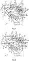
- FIG. 1 shows the open position of the door lock 1 with a door lock housing 2, which is arranged in a door 4 of an electrical household appliance, in particular a dishwasher.
- a striker 9 protrudes from the housing of a household appliance 5 in order to be brought into engagement with the lock mechanism 3 arranged in the door lock housing 2 through an opening 23.
- the striker 9 has a catch 8 for the engagement of a bolt 6 arranged in the door lock housing 2.
- the tip of the striker 9 has a closing surface 17 on the latch side and a butt surface 19 at the free end of the striker 9.
- On the underside of the striker 9 there is an oblique pressure surface 18.
- a lever element 12 which is rotatably mounted about an axis 24 and on which the bolt 6 is arranged.
- the spring element 7 is designed as a compression spring, which is in the open position under an adjustable bias to adjust the spring properties and spring forces for the function of the lock mechanism 3.
- the oblique arrangement of the spring element 7 in this exemplary embodiment results from the predetermined installation space in the door 4. In principle, with the corresponding installation space available, another arrangement of the spring element 7 with or without deflection is also possible.
- an actuator 20 which consists of parallel rollers 35, which can also be magnetic.
- the actuating element 20 bears with its end facing away from the locking bracket 9 against a rotating element 21 and together forms an actuator 10.
- the rollers 35 are guided at their ends in a recess 22 and laterally project beyond the rotating element 21, which has one end 21 'protrudes into the arcuate region 22' of the recess 22.
- the arcuate region 22 'of the recess 22 allows the actuating element 20 to be deflected by 180 °.
- the spring element 7 In the open position of the door lock 1 shown in this figure, the spring element 7 is in a relaxed position with respect to the closing process, the bolt 6 and also the actuating element 20 in a striker area 41 which is taken up by the striker 9 in its locking position.
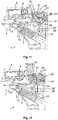
- FIG 2 accordingly shows the opposite side of the door lock 1.
- Tilting element 28 with two tilting element arms 28 ′, 28 ′′ which can be seen from the other side, is shown partially in section, which is rotatable about the axis 25 of the rotating element 21 mounted in the door lock housing 2.
- the lever element 12 Between the tilting element arms 28 ′, 28 ′′ is the lever element 12 with its axis 24 stored.
- a torsion spring 31 is arranged, which with a Arm engages in the rotating element 21 and rotates with it, while the other arm of the torsion spring 31 lies in a recess 40 in the tilting element arms 28 ', 28 "of the tilting element 28 and is supported on the tilting element arms 28', 28".
- a circuit board 32 with the associated control electronics is arranged outside the door lock housing 2, but connected to it.
- the control electronics also contain coils, not shown, arranged in the circuit board 32, via which a transmitter body 33 can be moved.
- the encoder body 33 can also be arranged on only one side of the circuit board 32. It is rigidly connected to the spring holder 15 and thus moves with it. By moving the transmitter body 33 along the coils (not shown), measurement signals can be generated in a known manner which are used to detect the current position of the bolt 6. These are essentially the open position and the locked position.
- the view according to Figure 3 shows the door lock housing 2 with a lifting magnet 11 arranged outside the door lock housing 2 with an armature 34 which engages on the axis 24 of the lever element 12 protruding from the door lock housing 2.
- the lifting magnet 11 is also connected to the door lock housing 2 like the circuit board 32.
- the figure also illustrates the rigid one-piece design of the spring holder 15 with the transmitter body 33.
- Figure 4 points to the open position again according to the Figure 1 in this figure and in the following, the sectional plane was placed partially deeper into the door lock housing 2, so that in particular the actuator 10 and the lever element 12 are shown in section in order to better illustrate the mode of operation.
- the rotating element 12 now lacks the counterforce, so that by the force of the spring element 7 as soon as the latch 8 is released for the bolt tip 37 by the further movement of the locking bracket 9, that the spring element 7 relaxes and the lever element 12 with the bolt 6 rotates back about the axis 24.
- the figure also clearly shows that compared to the Figure 6 changed position of the tilting element arm 28 "of the tilting element 28 can be seen.
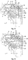
- the manual opening by hand by pulling in a handle, not shown, on the door 4 is in the Figures 10-12 shown and explained based on this.
- the striker 9 already leave its locking position and moved back somewhat.
- the closing surface 17 presses against the bolt tip 37 and thereby turns the lever element 12 against the Force of the spring element 7 about its axis 24 in the direction of the arrow.
- the in the Figure 2 The torsion spring 31 shown has actuated the actuator 10 due to the lack of a counterforce by the striker 9 and engages the rotating element 21, rotated it about its axis 25 in the direction of the arrow and thus also moved the actuating element 20 in the direction of the striker 9.
- the automatic opening is represented by an active element in the form of the lifting magnet 11 with its armature 34 acting on the axis 24 of the lever element 12.
- Figure 13 shows the locking position again according to the Figure 9 , wherein here the rotating element 21 and the lever element 12 are not shown in section and additionally the outside of the Door lock housing 2 arranged lifting magnet 11 is shown.
- the armature 34 moves with the closing movements of the lever element 12. It is only activated when, as described above, the user presses against the door 4, thereby squeezing the seal a little more and generating a signal that triggers the actuation of the solenoid 11, or the machine control triggers drying support.
- Figure 16 finally shows the position of the striker 9, the lever member 12 and the rocker member 22 in the same position as Figure 15 from the opposite side.
Landscapes
- Engineering & Computer Science (AREA)
- Mechanical Engineering (AREA)
- Physics & Mathematics (AREA)
- Electromagnetism (AREA)
- Structural Engineering (AREA)
- Lock And Its Accessories (AREA)
Claims (11)
- Procédé d'actionnement d'une serrure (1) de porte, munie d'un mécanisme (3) logé dans un boîtier (2) et dédiée à une porte (4) d'un appareil électroménager (5), de préférence un lave-vaisselle, dans lequel un loquet (6) est mû d'une position d'ouverture à une position de verrouillage au moyen d'un élément élastique (7), en vue du verrouillage, sachant que, dans ladite position d'ouverture, la porte (4) est ouverte et le loquet (6) n'est pas en prise avec une gâche (8) d'un arceau de fermeture (9) implanté sur l'appareil électroménager (5), et que, dans ladite position de verrouillage, ladite porte (4) est fermée, ledit arceau de fermeture (9) occupe un emplacement de verrouillage dans le boîtier (2) de la serrure de porte, et ledit loquet (6) est en prise avec ladite gâche (8),
sachant que, pour verrouiller la porte (4) à partir de la position d'ouverture, le loquet (6) est amené, sous la contrainte de l'élément élastique (7), à la position de verrouillage dans laquelle une force de fermeture, agissant sur ledit loquet (6), est déterminée par ledit élément élastique (7), et que,
pour déverrouiller ladite porte (4), ledit loquet (6) est amené de ladite position de verrouillage à une position de déverrouillage par une force d'actionnement non appliquée par ledit élément élastique (7) et, après que l'arceau de fermeture (9) a été mû à l'écart de l'emplacement de verrouillage, ledit loquet (6) est mû vers ladite position d'ouverture au moyen de la force dudit élément élastique (7),
caractérisé par le fait que,
pour verrouiller la porte (4), et donc pour mouvoir le loquet (6) à l'écart de la position d'ouverture, un actionneur (10) du mécanisme (3) de la serrure, situé à l'emplacement de verrouillage de l'arceau de fermeture (9), est pressé contre ledit arceau de fermeture (9) et ledit arceau de fermeture (9) parvient audit emplacement de verrouillage, par mouvement d'éloignement dudit actionneur (10), cependant que,
dans un premier temps, l'élément élastique (7) est bandé au moyen de l'arceau de fermeture (9), par l'intermédiaire de l'actionneur (10), et le loquet (6) est alors mû vers une position intermédiaire à partir de la position d'ouverture et,
dans l'enchaînement, ledit élément élastique (7) est soulagé en partie et ledit loquet (6) est alors mû vers la position de verrouillage, à partir de ladite position intermédiaire, avec maintien d'une contrainte résiduelle subsistante dudit élément élastique (7) qui constitue la force de fermeture. - Procédé selon la revendication 1, caractérisé par le fait que, pour instaurer le déverrouillage manuel par traction exercée sur la porte (4), le loquet (6) est mû vers une première position de déverrouillage à partir de la position de verrouillage, sous l'effet du mouvement relatif de l'arceau de fermeture (9) par rapport audit loquet (6), en opposition à la force de fermeture de l'élément élastique (7).
- Procédé selon la revendication 1, caractérisé par le fait que, pour instaurer le déverrouillage automatique, le loquet (6) est mû vers une seconde position de déverrouillage par l'intermédiaire d'un élément opérant électrique (11).
- Procédé selon l'une des revendications 2 ou 3, caractérisé par le fait que l'actionneur (10) est ramené à son emplacement de départ lorsque l'arceau de fermeture (9) quitte l'emplacement de verrouillage, ou après qu'il a quitté ce dernier.
- Serrure (1) de porte destinée à un appareil électroménager (5), de préférence à un lave-vaisselle, pour la mise en œuvre du procédé conforme à l'une des revendications 1 à 4, comprenant un boîtier (2) qui peut être intégré dans la porte (4) dudit appareil électroménager (5), et est muni d'un orifice (23) dédié à un arceau de fermeture (9) pouvant être fixé audit appareil électroménager (5),
un loquet (6) intégré dans ledit boîtier (2) de la serrure de porte et conçu pour venir se loger dans une gâche (8), située dans l'arceau de fermeture (9), dans une position de verrouillage dans laquelle ledit arceau de fermeture (9) occupe un emplacement de verrouillage, lequel loquet (6) est pourvu d'une surface de contact (37) et est relié à un élément (12) formant levier, monté à rotation autour d'un axe (24),
et un élément élastique (7), interposé entre ledit élément (12) formant levier et une contrebutée (13), sachant que, dans une position d'ouverture dans laquelle la porte (4) n'est pas verrouillée, ledit élément élastique (7) est soulagé relativement à une force de fermeture devant être appliquée et ledit élément (12), formant levier, maintient ledit loquet (6) dans une région (41) que ledit arceau de fermeture (9) vient occuper à l'emplacement de verrouillage,
caractérisée par un actionneur (10) incluant un élément flexible d'actionnement (20) et un élément rotatif (21), lequel est monté dans le boîtier (2) de la serrure de porte, peut tourner autour d'un axe (25), dans lequel l'élément flexible d'actionnement (20) est logé, dans la position d'ouverture, dans un évidement (22) pratiqué dans ledit boîtier (2) de la serrure de porte en s'engageant alors dans la région (41) de l'arceau de fermeture, et est logé, dans la position de verrouillage, dans une zone curviligne de guidage (22'), adjacente à ladite région (41) de l'arceau de fermeture, dudit évidement (22) pratiqué dans ledit boîtier (2) de la serrure de porte. - Serrure de porte, selon la revendication 5, caractérisée par le fait que l'élément rotatif (21) de l'actionneur (10), et l'élément (12) formant levier, sont pourvus de dents (27 ; 26) qui sont situées sur le pourtour et peuvent être mises en prise mutuelle et hors prise, sachant que, lors du mouvement de l'arceau de fermeture (9) vers l'emplacement de verrouillage, les dents (27) dudit élément rotatif (21) et les dents (26) dudit élément (12) formant levier viennent tout d'abord en prise de façon telle que l'élément d'actionnement (20) imprime une rotation audit élément (12) formant levier, autour de son axe (24), lequel élément bande alors l'élément élastique (7), et que la prise desdites dents (26 ; 27) est supprimée à l'instant auquel une position intermédiaire est atteinte, de telle sorte que ledit élément élastique (7) se détende, avec maintien d'une contrainte résiduelle subsistante, et imprime une rotation rétrograde audit élément (12) formant levier, autour de son axe (24), jusqu'à ce que le loquet (6) repose dans la gâche (8) de l'arceau de fermeture (9), par sa surface de contact (37), et exerce une pression contre ledit arceau de fermeture (9) avec une force de fermeture résultant de ladite contrainte résiduelle.
- Serrure de porte, selon la revendication 5 ou 6, caractérisée par le fait que l'élément (12) formant levier est monté sur l'axe (25) de l'élément rotatif (21), par son axe (24), au moyen d'un appui basculant.
- Serrure de porte, selon la revendication 7, caractérisée par le fait que l'arceau de fermeture (9) pousse le loquet (6) hors de la région (41) dudit arceau de fermeture, au moyen de l'appui basculant de l'élément (12) formant levier, jusqu'à ce que la position intermédiaire soit atteinte.
- Serrure de porte, selon l'une des revendications 5 à 8 précédentes, caractérisée par le fait que, pour instaurer le déverrouillage manuel par traction exercée sur la porte (4) par l'intermédiaire du loquet (6), sous l'effet d'un mouvement relatif de l'arceau de fermeture (9) par rapport audit loquet (6) en opposition à la force de fermeture de l'élément élastique (7), l'élément (12) formant levier tourne autour de son axe (24), au moins en partie, jusqu'à ce que ledit loquet (6) soit parvenu hors de la gâche (8) dudit arceau de fermeture (9) soit uniquement sous l'effet du mouvement rotatoire, soit sous l'action d'une force appliquée à l'appui basculant par ledit arceau de fermeture (9).
- Serrure de porte, selon l'une des revendications 7 ou 8 précédentes, caractérisée par le fait qu'un élément opérant électromagnétique (11), de préférence un aimant de levage, vient en prise avec l'axe (24) de l'élément (12) formant levier de façon telle que, pour ouvrir le loquet (6), ledit élément (12) formant levier puisse être mû au moyen de l'appui basculant, par application de force, à l'écart de sa position occupée lors du verrouillage.
- Serrure de porte, selon l'une des revendications 9 ou 10, caractérisée par le fait que l'élément élastique (7) imprime à l'élément (12) formant levier, lors du soulagement, un mouvement vers la position d'ouverture dans laquelle le loquet (6) se trouve dans la région (41) de l'arceau de fermeture (9) présentant l'évidement (22).
Priority Applications (2)
| Application Number | Priority Date | Filing Date | Title |
|---|---|---|---|
| EP16204036.4A EP3336292B1 (fr) | 2016-12-14 | 2016-12-14 | Procédé d'actionnement d'une serrure de porte et serrure de porte |
| US15/837,354 US11015371B2 (en) | 2016-12-14 | 2017-12-11 | Method for actuating a door lock, and door lock |
Applications Claiming Priority (1)
| Application Number | Priority Date | Filing Date | Title |
|---|---|---|---|
| EP16204036.4A EP3336292B1 (fr) | 2016-12-14 | 2016-12-14 | Procédé d'actionnement d'une serrure de porte et serrure de porte |
Publications (2)
| Publication Number | Publication Date |
|---|---|
| EP3336292A1 EP3336292A1 (fr) | 2018-06-20 |
| EP3336292B1 true EP3336292B1 (fr) | 2020-04-08 |
Family
ID=57569993
Family Applications (1)
| Application Number | Title | Priority Date | Filing Date |
|---|---|---|---|
| EP16204036.4A Active EP3336292B1 (fr) | 2016-12-14 | 2016-12-14 | Procédé d'actionnement d'une serrure de porte et serrure de porte |
Country Status (2)
| Country | Link |
|---|---|
| US (1) | US11015371B2 (fr) |
| EP (1) | EP3336292B1 (fr) |
Families Citing this family (11)
| Publication number | Priority date | Publication date | Assignee | Title |
|---|---|---|---|---|
| WO2018169755A1 (fr) * | 2017-03-14 | 2018-09-20 | Illinois Tool Works, Inc. | Verrou de porte |
| TR201707943A2 (tr) * | 2017-05-30 | 2018-12-21 | Serdar Plastik Sanayi Ve Ticaret Anonim Sirketi | Kendi̇nden ayarlanan ki̇li̇t si̇stemi̇ |
| DE102017006649B3 (de) * | 2017-07-13 | 2018-09-27 | Emz-Hanauer Gmbh & Co. Kgaa | Türverschluss für ein elektrisches Haushaltsgerät |
| IT201700084013A1 (it) * | 2017-07-24 | 2019-01-24 | Illinois Tool Works | Dispositivo blocco-porta per elettrodomestici, in particolare per lavastoviglie |
| US11359414B2 (en) | 2019-01-24 | 2022-06-14 | Whirlpool Corporation | Latch assembly |
| US20210238888A1 (en) * | 2020-01-31 | 2021-08-05 | Bitron S.P.A. | Door-lock device and household appliance equipped with such door-lock device |
| CN113143159B (zh) * | 2021-04-12 | 2025-06-27 | 珠海格力电器股份有限公司 | 门锁和洗碗机 |
| DE102022116999B4 (de) * | 2022-07-07 | 2024-02-15 | Emz-Hanauer Gmbh & Co. Kgaa | Türverschluss mit Selbstheilung |
| US20240335087A1 (en) * | 2023-04-06 | 2024-10-10 | Illinois Tool Works Inc. | Dishwasher latch resistant to sticking from food soils |
| DE102023123152A1 (de) * | 2023-08-29 | 2025-03-06 | Emz-Hanauer Gmbh & Co. Kgaa | Türschlossmechanismus für Haushaltsgeräte |
| EP4567229A1 (fr) * | 2023-12-05 | 2025-06-11 | Quadient Technologies France | Système de verrouillage amélioré pour une porte d'un compartiment d'une banque de casiers de colis |
Family Cites Families (30)
| Publication number | Priority date | Publication date | Assignee | Title |
|---|---|---|---|---|
| US959241A (en) * | 1909-03-29 | 1910-05-24 | George W Mallory | Door catch or check. |
| US1090305A (en) * | 1912-07-31 | 1914-03-17 | Richards Wilcox Mfg Co | Sliding-door lock. |
| US1269467A (en) * | 1915-12-01 | 1918-06-11 | Grand Rapids Refrigerator Company | Refrigerator-latch. |
| US1302168A (en) * | 1918-04-30 | 1919-04-29 | Stanley R Hughes | Door-catch. |
| US1396163A (en) * | 1920-02-28 | 1921-11-08 | Cleal Joseph Pacy | Lock |
| GB395910A (en) * | 1932-10-18 | 1933-07-27 | William Francis Banham | Improvements in or relating to door fastenings |
| US2129926A (en) * | 1936-11-30 | 1938-09-13 | Winters & Crampton Corp | Refrigerator latch |
| US2359150A (en) * | 1941-07-10 | 1944-09-26 | Westinghouse Electric & Mfg Co | Latch construction |
| US2348955A (en) * | 1942-01-08 | 1944-05-16 | Westinghouse Electric & Mfg Co | Door latch mechanism |
| US2341416A (en) * | 1942-09-07 | 1944-02-08 | Winters & Crampton Corp | Latch mechanism |
| US2698197A (en) * | 1949-08-01 | 1954-12-28 | Edwin B Jacobson | Door latch mechanism |
| US2679428A (en) * | 1952-03-13 | 1954-05-25 | Jervis Corp | Latch mechanism |
| US2833578A (en) * | 1956-11-14 | 1958-05-06 | Nat Lock Co | Refrigerator latch mechanism |
| US3041098A (en) * | 1959-06-18 | 1962-06-26 | Stanley Works | Latch assembly for surface-mounted doors |
| US3968984A (en) * | 1975-04-14 | 1976-07-13 | General Electric Company | Door latch |
| US4210349A (en) * | 1978-12-26 | 1980-07-01 | Standard Keil Hardware Manufacturing Co. | Device for holding a door firmly closed |
| US5518282A (en) * | 1993-11-30 | 1996-05-21 | Koei Sangyo Co., Ltd. | Locking device for open-close mechanism of a cabinet |
| US5595409A (en) * | 1994-07-05 | 1997-01-21 | Anderson Corporation | Gliding door latch assembly |
| DE19504797C2 (de) * | 1995-02-14 | 1997-04-24 | Ymos Ag Ind Produkte | Schließvorrichtung für die Tür einer Spülmaschine |
| DE19540843C2 (de) * | 1995-10-30 | 1998-07-02 | Zangenstein Elektro | Verschluß für eine Tür eines elektrischen Haushaltsgerätes |
| FR2749343B1 (fr) * | 1996-06-04 | 1999-02-26 | Sirandre Sa | Dispositif de fermeture de porte a commande electrique |
| DE19837248C2 (de) | 1998-07-28 | 2000-05-31 | Zangenstein Elektro | Türschloß für ein elektrisches Haushaltsgerät |
| DE19944050A1 (de) * | 1999-09-14 | 2001-03-15 | Wilke Heinrich Hewi Gmbh | Verriegelungsvorrichtung |
| US6733051B1 (en) * | 2000-11-23 | 2004-05-11 | Banham Patent Locks Limited | Door fastening device |
| EP1212973B1 (fr) * | 2000-12-01 | 2007-07-04 | emz-Hanauer GmbH & Co. KGaA | Verrou de porte |
| DE10350710B4 (de) * | 2003-10-30 | 2021-01-07 | Marquardt Gmbh | Verschluß für ein Hausgerät |
| ITTO20040534A1 (it) * | 2004-07-30 | 2004-10-30 | Itw Ind Components Srl | Dispositivo di incaglio per una porta di un elettrodomestico, in particolare una lavastoviglie |
| US7255375B2 (en) * | 2004-11-22 | 2007-08-14 | Newell Operating Company | Reach out lock |
| DE102007044577B4 (de) * | 2007-09-19 | 2009-11-05 | Emz-Hanauer Gmbh & Co. Kgaa | Türschließvorrichtung für ein elektrisches Haushaltsgerät |
| US9267315B2 (en) * | 2013-03-18 | 2016-02-23 | Poong Won Industry Co., Ltd. | Door safety locking apparatus |
-
2016
- 2016-12-14 EP EP16204036.4A patent/EP3336292B1/fr active Active
-
2017
- 2017-12-11 US US15/837,354 patent/US11015371B2/en not_active Expired - Fee Related
Non-Patent Citations (1)
| Title |
|---|
| None * |
Also Published As
| Publication number | Publication date |
|---|---|
| US11015371B2 (en) | 2021-05-25 |
| US20180163433A1 (en) | 2018-06-14 |
| EP3336292A1 (fr) | 2018-06-20 |
Similar Documents
| Publication | Publication Date | Title |
|---|---|---|
| EP3336292B1 (fr) | Procédé d'actionnement d'une serrure de porte et serrure de porte | |
| EP2326781B1 (fr) | Unité de serrure comportant des cliquets d'arrêt à plusieurs parties et un cliquet de blocage précontraint par ressort | |
| DE60217285T2 (de) | Kraftfahrzeugtürsystem mit Verriegelungsanzeige | |
| DE102017006649B3 (de) | Türverschluss für ein elektrisches Haushaltsgerät | |
| DE102018123949A1 (de) | Betätigungsvorrichtung | |
| EP2828456B1 (fr) | Verrouillage de portière de véhicule automobile | |
| DE102011076704A1 (de) | Schloss für eine Klappe oder Tür | |
| EP0481503A1 (fr) | Verrouillage de porte pour appareil ménager | |
| DE2633218C3 (de) | Antriebsmechanismus für die Kontaktbewegung in einem Leistungsschalter | |
| DE10331080A1 (de) | Kraftfahrzeugtürverschluss | |
| DE10360225B3 (de) | Elektrisch betätigbarer Türöffner | |
| EP0853176B1 (fr) | Dispositif d'ouverture de porte | |
| EP3222802B1 (fr) | Dispositif d'actionnement d'une serrure de porte coulissante d'un véhicule automobile | |
| EP1460163B1 (fr) | Verrouillage de porte pour appareil électrique, en particulier pour machine à laver. | |
| WO2017182023A1 (fr) | Assistance à la fermeture pour véhicules automobiles | |
| DE202009012289U1 (de) | Elektronisches Verschlusssystem für Schränke mit einer im Schrankinneren angeordneten elektromotorisch gesteuerten Verriegelungsmechanik | |
| EP1201853B1 (fr) | Dispositif de fermeture supérieur pour serrure des portes de secours | |
| DE10151870A1 (de) | Vorrichtung zur Betätigung eines Verschlusses von Türen oder Klappen, insbesondere an Fahrzeugen | |
| EP1672153A1 (fr) | Serrure avec pêne dormant et dispositif de commande du pêne dormant | |
| DE10140957A1 (de) | Kraftfahrzeugtürverschluss | |
| DE10232184A1 (de) | Übertragungseinheit für Türschlösser von Kraftfahrzeugen | |
| DE102012110026A1 (de) | Feststellvorrichtung für eine Tür und Verfahren zum Betrieb der Feststellvorrichtung | |
| DE102012010438B4 (de) | Türöffner mit Sperr-Riegel | |
| WO2017005247A1 (fr) | Dispositif d'actionnement pour serrure de véhicule à moteur | |
| DE102024103537A1 (de) | Vorrichtung zur mechanischen Schließfolgeregelung |
Legal Events
| Date | Code | Title | Description |
|---|---|---|---|
| PUAI | Public reference made under article 153(3) epc to a published international application that has entered the european phase |
Free format text: ORIGINAL CODE: 0009012 |
|
| STAA | Information on the status of an ep patent application or granted ep patent |
Free format text: STATUS: REQUEST FOR EXAMINATION WAS MADE |
|
| 17P | Request for examination filed |
Effective date: 20171123 |
|
| AK | Designated contracting states |
Kind code of ref document: A1 Designated state(s): AL AT BE BG CH CY CZ DE DK EE ES FI FR GB GR HR HU IE IS IT LI LT LU LV MC MK MT NL NO PL PT RO RS SE SI SK SM TR |
|
| AX | Request for extension of the european patent |
Extension state: BA ME |
|
| RBV | Designated contracting states (corrected) |
Designated state(s): AL AT BE BG CH CY CZ DE DK EE ES FI FR GB GR HR HU IE IS IT LI LT LU LV MC MK MT NL NO PL PT RO RS SE SI SK SM TR |
|
| GRAP | Despatch of communication of intention to grant a patent |
Free format text: ORIGINAL CODE: EPIDOSNIGR1 |
|
| STAA | Information on the status of an ep patent application or granted ep patent |
Free format text: STATUS: GRANT OF PATENT IS INTENDED |
|
| RIC1 | Information provided on ipc code assigned before grant |
Ipc: E05C 3/22 20060101ALI20190920BHEP Ipc: E05C 19/02 20060101AFI20190920BHEP Ipc: E05C 5/00 20060101ALN20190920BHEP Ipc: E05B 17/00 20060101ALI20190920BHEP Ipc: E05B 53/00 20060101ALN20190920BHEP Ipc: E05B 47/00 20060101ALN20190920BHEP Ipc: E05B 15/04 20060101ALI20190920BHEP Ipc: A47L 15/42 20060101ALI20190920BHEP |
|
| INTG | Intention to grant announced |
Effective date: 20191015 |
|
| GRAS | Grant fee paid |
Free format text: ORIGINAL CODE: EPIDOSNIGR3 |
|
| GRAJ | Information related to disapproval of communication of intention to grant by the applicant or resumption of examination proceedings by the epo deleted |
Free format text: ORIGINAL CODE: EPIDOSDIGR1 |
|
| GRAL | Information related to payment of fee for publishing/printing deleted |
Free format text: ORIGINAL CODE: EPIDOSDIGR3 |
|
| STAA | Information on the status of an ep patent application or granted ep patent |
Free format text: STATUS: REQUEST FOR EXAMINATION WAS MADE |
|
| GRAP | Despatch of communication of intention to grant a patent |
Free format text: ORIGINAL CODE: EPIDOSNIGR1 |
|
| STAA | Information on the status of an ep patent application or granted ep patent |
Free format text: STATUS: GRANT OF PATENT IS INTENDED |
|
| GRAA | (expected) grant |
Free format text: ORIGINAL CODE: 0009210 |
|
| STAA | Information on the status of an ep patent application or granted ep patent |
Free format text: STATUS: THE PATENT HAS BEEN GRANTED |
|
| INTC | Intention to grant announced (deleted) | ||
| RIC1 | Information provided on ipc code assigned before grant |
Ipc: E05B 53/00 20060101ALN20200213BHEP Ipc: E05B 15/04 20060101ALI20200213BHEP Ipc: E05B 17/00 20060101ALI20200213BHEP Ipc: E05B 47/00 20060101ALN20200213BHEP Ipc: E05C 19/02 20060101AFI20200213BHEP Ipc: E05C 3/22 20060101ALI20200213BHEP Ipc: E05C 5/00 20060101ALN20200213BHEP Ipc: A47L 15/42 20060101ALI20200213BHEP |
|
| INTG | Intention to grant announced |
Effective date: 20200225 |
|
| AK | Designated contracting states |
Kind code of ref document: B1 Designated state(s): AL AT BE BG CH CY CZ DE DK EE ES FI FR GB GR HR HU IE IS IT LI LT LU LV MC MK MT NL NO PL PT RO RS SE SI SK SM TR |
|
| REG | Reference to a national code |
Ref country code: AT Ref legal event code: REF Ref document number: 1254600 Country of ref document: AT Kind code of ref document: T Effective date: 20200415 Ref country code: CH Ref legal event code: EP |
|
| REG | Reference to a national code |
Ref country code: DE Ref legal event code: R096 Ref document number: 502016009452 Country of ref document: DE |
|
| REG | Reference to a national code |
Ref country code: IE Ref legal event code: FG4D Free format text: LANGUAGE OF EP DOCUMENT: GERMAN |
|
| REG | Reference to a national code |
Ref country code: CH Ref legal event code: NV Representative=s name: ABACUS PATENTANWAELTE KLOCKE SPAETH BARTH, CH |
|
| REG | Reference to a national code |
Ref country code: NL Ref legal event code: MP Effective date: 20200408 |
|
| REG | Reference to a national code |
Ref country code: LT Ref legal event code: MG4D |
|
| PG25 | Lapsed in a contracting state [announced via postgrant information from national office to epo] |
Ref country code: NO Free format text: LAPSE BECAUSE OF FAILURE TO SUBMIT A TRANSLATION OF THE DESCRIPTION OR TO PAY THE FEE WITHIN THE PRESCRIBED TIME-LIMIT Effective date: 20200708 Ref country code: FI Free format text: LAPSE BECAUSE OF FAILURE TO SUBMIT A TRANSLATION OF THE DESCRIPTION OR TO PAY THE FEE WITHIN THE PRESCRIBED TIME-LIMIT Effective date: 20200408 Ref country code: IS Free format text: LAPSE BECAUSE OF FAILURE TO SUBMIT A TRANSLATION OF THE DESCRIPTION OR TO PAY THE FEE WITHIN THE PRESCRIBED TIME-LIMIT Effective date: 20200808 Ref country code: SE Free format text: LAPSE BECAUSE OF FAILURE TO SUBMIT A TRANSLATION OF THE DESCRIPTION OR TO PAY THE FEE WITHIN THE PRESCRIBED TIME-LIMIT Effective date: 20200408 Ref country code: PT Free format text: LAPSE BECAUSE OF FAILURE TO SUBMIT A TRANSLATION OF THE DESCRIPTION OR TO PAY THE FEE WITHIN THE PRESCRIBED TIME-LIMIT Effective date: 20200817 Ref country code: GR Free format text: LAPSE BECAUSE OF FAILURE TO SUBMIT A TRANSLATION OF THE DESCRIPTION OR TO PAY THE FEE WITHIN THE PRESCRIBED TIME-LIMIT Effective date: 20200709 Ref country code: LT Free format text: LAPSE BECAUSE OF FAILURE TO SUBMIT A TRANSLATION OF THE DESCRIPTION OR TO PAY THE FEE WITHIN THE PRESCRIBED TIME-LIMIT Effective date: 20200408 Ref country code: NL Free format text: LAPSE BECAUSE OF FAILURE TO SUBMIT A TRANSLATION OF THE DESCRIPTION OR TO PAY THE FEE WITHIN THE PRESCRIBED TIME-LIMIT Effective date: 20200408 |
|
| PG25 | Lapsed in a contracting state [announced via postgrant information from national office to epo] |
Ref country code: LV Free format text: LAPSE BECAUSE OF FAILURE TO SUBMIT A TRANSLATION OF THE DESCRIPTION OR TO PAY THE FEE WITHIN THE PRESCRIBED TIME-LIMIT Effective date: 20200408 Ref country code: BG Free format text: LAPSE BECAUSE OF FAILURE TO SUBMIT A TRANSLATION OF THE DESCRIPTION OR TO PAY THE FEE WITHIN THE PRESCRIBED TIME-LIMIT Effective date: 20200708 Ref country code: RS Free format text: LAPSE BECAUSE OF FAILURE TO SUBMIT A TRANSLATION OF THE DESCRIPTION OR TO PAY THE FEE WITHIN THE PRESCRIBED TIME-LIMIT Effective date: 20200408 Ref country code: HR Free format text: LAPSE BECAUSE OF FAILURE TO SUBMIT A TRANSLATION OF THE DESCRIPTION OR TO PAY THE FEE WITHIN THE PRESCRIBED TIME-LIMIT Effective date: 20200408 |
|
| PG25 | Lapsed in a contracting state [announced via postgrant information from national office to epo] |
Ref country code: AL Free format text: LAPSE BECAUSE OF FAILURE TO SUBMIT A TRANSLATION OF THE DESCRIPTION OR TO PAY THE FEE WITHIN THE PRESCRIBED TIME-LIMIT Effective date: 20200408 |
|
| REG | Reference to a national code |
Ref country code: DE Ref legal event code: R097 Ref document number: 502016009452 Country of ref document: DE |
|
| PG25 | Lapsed in a contracting state [announced via postgrant information from national office to epo] |
Ref country code: DK Free format text: LAPSE BECAUSE OF FAILURE TO SUBMIT A TRANSLATION OF THE DESCRIPTION OR TO PAY THE FEE WITHIN THE PRESCRIBED TIME-LIMIT Effective date: 20200408 Ref country code: IT Free format text: LAPSE BECAUSE OF FAILURE TO SUBMIT A TRANSLATION OF THE DESCRIPTION OR TO PAY THE FEE WITHIN THE PRESCRIBED TIME-LIMIT Effective date: 20200408 Ref country code: CZ Free format text: LAPSE BECAUSE OF FAILURE TO SUBMIT A TRANSLATION OF THE DESCRIPTION OR TO PAY THE FEE WITHIN THE PRESCRIBED TIME-LIMIT Effective date: 20200408 Ref country code: ES Free format text: LAPSE BECAUSE OF FAILURE TO SUBMIT A TRANSLATION OF THE DESCRIPTION OR TO PAY THE FEE WITHIN THE PRESCRIBED TIME-LIMIT Effective date: 20200408 Ref country code: RO Free format text: LAPSE BECAUSE OF FAILURE TO SUBMIT A TRANSLATION OF THE DESCRIPTION OR TO PAY THE FEE WITHIN THE PRESCRIBED TIME-LIMIT Effective date: 20200408 Ref country code: EE Free format text: LAPSE BECAUSE OF FAILURE TO SUBMIT A TRANSLATION OF THE DESCRIPTION OR TO PAY THE FEE WITHIN THE PRESCRIBED TIME-LIMIT Effective date: 20200408 Ref country code: SM Free format text: LAPSE BECAUSE OF FAILURE TO SUBMIT A TRANSLATION OF THE DESCRIPTION OR TO PAY THE FEE WITHIN THE PRESCRIBED TIME-LIMIT Effective date: 20200408 |
|
| PLBE | No opposition filed within time limit |
Free format text: ORIGINAL CODE: 0009261 |
|
| STAA | Information on the status of an ep patent application or granted ep patent |
Free format text: STATUS: NO OPPOSITION FILED WITHIN TIME LIMIT |
|
| PG25 | Lapsed in a contracting state [announced via postgrant information from national office to epo] |
Ref country code: SK Free format text: LAPSE BECAUSE OF FAILURE TO SUBMIT A TRANSLATION OF THE DESCRIPTION OR TO PAY THE FEE WITHIN THE PRESCRIBED TIME-LIMIT Effective date: 20200408 Ref country code: PL Free format text: LAPSE BECAUSE OF FAILURE TO SUBMIT A TRANSLATION OF THE DESCRIPTION OR TO PAY THE FEE WITHIN THE PRESCRIBED TIME-LIMIT Effective date: 20200408 |
|
| 26N | No opposition filed |
Effective date: 20210112 |
|
| PG25 | Lapsed in a contracting state [announced via postgrant information from national office to epo] |
Ref country code: SI Free format text: LAPSE BECAUSE OF FAILURE TO SUBMIT A TRANSLATION OF THE DESCRIPTION OR TO PAY THE FEE WITHIN THE PRESCRIBED TIME-LIMIT Effective date: 20200408 |
|
| GBPC | Gb: european patent ceased through non-payment of renewal fee |
Effective date: 20201214 |
|
| PG25 | Lapsed in a contracting state [announced via postgrant information from national office to epo] |
Ref country code: MC Free format text: LAPSE BECAUSE OF FAILURE TO SUBMIT A TRANSLATION OF THE DESCRIPTION OR TO PAY THE FEE WITHIN THE PRESCRIBED TIME-LIMIT Effective date: 20200408 |
|
| REG | Reference to a national code |
Ref country code: BE Ref legal event code: MM Effective date: 20201231 |
|
| PG25 | Lapsed in a contracting state [announced via postgrant information from national office to epo] |
Ref country code: IE Free format text: LAPSE BECAUSE OF NON-PAYMENT OF DUE FEES Effective date: 20201214 Ref country code: LU Free format text: LAPSE BECAUSE OF NON-PAYMENT OF DUE FEES Effective date: 20201214 Ref country code: FR Free format text: LAPSE BECAUSE OF NON-PAYMENT OF DUE FEES Effective date: 20201231 |
|
| PG25 | Lapsed in a contracting state [announced via postgrant information from national office to epo] |
Ref country code: GB Free format text: LAPSE BECAUSE OF NON-PAYMENT OF DUE FEES Effective date: 20201214 |
|
| REG | Reference to a national code |
Ref country code: DE Ref legal event code: R082 Ref document number: 502016009452 Country of ref document: DE Representative=s name: WITTE, WELLER & PARTNER PATENTANWAELTE MBB, DE |
|
| PG25 | Lapsed in a contracting state [announced via postgrant information from national office to epo] |
Ref country code: TR Free format text: LAPSE BECAUSE OF FAILURE TO SUBMIT A TRANSLATION OF THE DESCRIPTION OR TO PAY THE FEE WITHIN THE PRESCRIBED TIME-LIMIT Effective date: 20200408 Ref country code: MT Free format text: LAPSE BECAUSE OF FAILURE TO SUBMIT A TRANSLATION OF THE DESCRIPTION OR TO PAY THE FEE WITHIN THE PRESCRIBED TIME-LIMIT Effective date: 20200408 Ref country code: CY Free format text: LAPSE BECAUSE OF FAILURE TO SUBMIT A TRANSLATION OF THE DESCRIPTION OR TO PAY THE FEE WITHIN THE PRESCRIBED TIME-LIMIT Effective date: 20200408 |
|
| PG25 | Lapsed in a contracting state [announced via postgrant information from national office to epo] |
Ref country code: MK Free format text: LAPSE BECAUSE OF FAILURE TO SUBMIT A TRANSLATION OF THE DESCRIPTION OR TO PAY THE FEE WITHIN THE PRESCRIBED TIME-LIMIT Effective date: 20200408 |
|
| PG25 | Lapsed in a contracting state [announced via postgrant information from national office to epo] |
Ref country code: BE Free format text: LAPSE BECAUSE OF NON-PAYMENT OF DUE FEES Effective date: 20201231 |
|
| REG | Reference to a national code |
Ref country code: AT Ref legal event code: MM01 Ref document number: 1254600 Country of ref document: AT Kind code of ref document: T Effective date: 20211214 |
|
| PG25 | Lapsed in a contracting state [announced via postgrant information from national office to epo] |
Ref country code: AT Free format text: LAPSE BECAUSE OF NON-PAYMENT OF DUE FEES Effective date: 20211214 |
|
| PGFP | Annual fee paid to national office [announced via postgrant information from national office to epo] |
Ref country code: DE Payment date: 20240129 Year of fee payment: 8 |
|
| PGFP | Annual fee paid to national office [announced via postgrant information from national office to epo] |
Ref country code: CH Payment date: 20250101 Year of fee payment: 9 |
|
| REG | Reference to a national code |
Ref country code: DE Ref legal event code: R119 Ref document number: 502016009452 Country of ref document: DE |
|
| PG25 | Lapsed in a contracting state [announced via postgrant information from national office to epo] |
Ref country code: DE Free format text: LAPSE BECAUSE OF NON-PAYMENT OF DUE FEES Effective date: 20250701 |
|
| PG25 | Lapsed in a contracting state [announced via postgrant information from national office to epo] |
Ref country code: IS Free format text: LAPSE BECAUSE OF NON-PAYMENT OF DUE FEES Effective date: 20200808 |
|
| REG | Reference to a national code |
Ref country code: CH Ref legal event code: U11 Free format text: ST27 STATUS EVENT CODE: U-0-0-U10-U11 (AS PROVIDED BY THE NATIONAL OFFICE) Effective date: 20260101 |