EP3336334A1 - Transmission à entraînement par traction pour boîte de vitesses d'accessoire de moteur à turbine à gaz - Google Patents
Transmission à entraînement par traction pour boîte de vitesses d'accessoire de moteur à turbine à gaz Download PDFInfo
- Publication number
- EP3336334A1 EP3336334A1 EP17207856.0A EP17207856A EP3336334A1 EP 3336334 A1 EP3336334 A1 EP 3336334A1 EP 17207856 A EP17207856 A EP 17207856A EP 3336334 A1 EP3336334 A1 EP 3336334A1
- Authority
- EP
- European Patent Office
- Prior art keywords
- towershaft
- turbine
- shaft
- gears
- gas turbine
- Prior art date
- Legal status (The legal status is an assumption and is not a legal conclusion. Google has not performed a legal analysis and makes no representation as to the accuracy of the status listed.)
- Granted
Links
Images

Classifications
-
- F—MECHANICAL ENGINEERING; LIGHTING; HEATING; WEAPONS; BLASTING
- F01—MACHINES OR ENGINES IN GENERAL; ENGINE PLANTS IN GENERAL; STEAM ENGINES
- F01D—NON-POSITIVE DISPLACEMENT MACHINES OR ENGINES, e.g. STEAM TURBINES
- F01D15/00—Adaptations of machines or engines for special use; Combinations of engines with devices driven thereby
- F01D15/12—Combinations with mechanical gearing
-
- F—MECHANICAL ENGINEERING; LIGHTING; HEATING; WEAPONS; BLASTING
- F01—MACHINES OR ENGINES IN GENERAL; ENGINE PLANTS IN GENERAL; STEAM ENGINES
- F01D—NON-POSITIVE DISPLACEMENT MACHINES OR ENGINES, e.g. STEAM TURBINES
- F01D15/00—Adaptations of machines or engines for special use; Combinations of engines with devices driven thereby
- F01D15/10—Adaptations for driving, or combinations with, electric generators
-
- F—MECHANICAL ENGINEERING; LIGHTING; HEATING; WEAPONS; BLASTING
- F01—MACHINES OR ENGINES IN GENERAL; ENGINE PLANTS IN GENERAL; STEAM ENGINES
- F01D—NON-POSITIVE DISPLACEMENT MACHINES OR ENGINES, e.g. STEAM TURBINES
- F01D15/00—Adaptations of machines or engines for special use; Combinations of engines with devices driven thereby
- F01D15/08—Adaptations for driving, or combinations with, pumps
-
- F—MECHANICAL ENGINEERING; LIGHTING; HEATING; WEAPONS; BLASTING
- F01—MACHINES OR ENGINES IN GENERAL; ENGINE PLANTS IN GENERAL; STEAM ENGINES
- F01D—NON-POSITIVE DISPLACEMENT MACHINES OR ENGINES, e.g. STEAM TURBINES
- F01D25/00—Component parts, details, or accessories, not provided for in, or of interest apart from, other groups
- F01D25/18—Lubricating arrangements
- F01D25/20—Lubricating arrangements using lubrication pumps
-
- F—MECHANICAL ENGINEERING; LIGHTING; HEATING; WEAPONS; BLASTING
- F02—COMBUSTION ENGINES; HOT-GAS OR COMBUSTION-PRODUCT ENGINE PLANTS
- F02C—GAS-TURBINE PLANTS; AIR INTAKES FOR JET-PROPULSION PLANTS; CONTROLLING FUEL SUPPLY IN AIR-BREATHING JET-PROPULSION PLANTS
- F02C7/00—Features, components parts, details or accessories, not provided for in, or of interest apart form groups F02C1/00 - F02C6/00; Air intakes for jet-propulsion plants
- F02C7/32—Arrangement, mounting, or driving, of auxiliaries
-
- F—MECHANICAL ENGINEERING; LIGHTING; HEATING; WEAPONS; BLASTING
- F02—COMBUSTION ENGINES; HOT-GAS OR COMBUSTION-PRODUCT ENGINE PLANTS
- F02C—GAS-TURBINE PLANTS; AIR INTAKES FOR JET-PROPULSION PLANTS; CONTROLLING FUEL SUPPLY IN AIR-BREATHING JET-PROPULSION PLANTS
- F02C7/00—Features, components parts, details or accessories, not provided for in, or of interest apart form groups F02C1/00 - F02C6/00; Air intakes for jet-propulsion plants
- F02C7/36—Power transmission arrangements between the different shafts of the gas turbine plant, or between the gas-turbine plant and the power user
-
- F—MECHANICAL ENGINEERING; LIGHTING; HEATING; WEAPONS; BLASTING
- F16—ENGINEERING ELEMENTS AND UNITS; GENERAL MEASURES FOR PRODUCING AND MAINTAINING EFFECTIVE FUNCTIONING OF MACHINES OR INSTALLATIONS; THERMAL INSULATION IN GENERAL
- F16H—GEARING
- F16H1/00—Toothed gearings for conveying rotary motion
- F16H1/02—Toothed gearings for conveying rotary motion without gears having orbital motion
- F16H1/20—Toothed gearings for conveying rotary motion without gears having orbital motion involving more than two intermeshing members
- F16H1/22—Toothed gearings for conveying rotary motion without gears having orbital motion involving more than two intermeshing members with a plurality of driving or driven shafts; with arrangements for dividing torque between two or more intermediate shafts
- F16H1/222—Toothed gearings for conveying rotary motion without gears having orbital motion involving more than two intermeshing members with a plurality of driving or driven shafts; with arrangements for dividing torque between two or more intermediate shafts with non-parallel axes
-
- F—MECHANICAL ENGINEERING; LIGHTING; HEATING; WEAPONS; BLASTING
- F16—ENGINEERING ELEMENTS AND UNITS; GENERAL MEASURES FOR PRODUCING AND MAINTAINING EFFECTIVE FUNCTIONING OF MACHINES OR INSTALLATIONS; THERMAL INSULATION IN GENERAL
- F16H—GEARING
- F16H15/00—Gearings for conveying rotary motion with variable gear ratio, or for reversing rotary motion, by friction between rotary members
- F16H15/02—Gearings for conveying rotary motion with variable gear ratio, or for reversing rotary motion, by friction between rotary members without members having orbital motion
- F16H15/04—Gearings providing a continuous range of gear ratios
-
- F—MECHANICAL ENGINEERING; LIGHTING; HEATING; WEAPONS; BLASTING
- F16—ENGINEERING ELEMENTS AND UNITS; GENERAL MEASURES FOR PRODUCING AND MAINTAINING EFFECTIVE FUNCTIONING OF MACHINES OR INSTALLATIONS; THERMAL INSULATION IN GENERAL
- F16H—GEARING
- F16H37/00—Combinations of mechanical gearings, not provided for in groups F16H1/00 - F16H35/00
- F16H37/02—Combinations of mechanical gearings, not provided for in groups F16H1/00 - F16H35/00 comprising essentially only toothed or friction gearings
- F16H37/021—Combinations of mechanical gearings, not provided for in groups F16H1/00 - F16H35/00 comprising essentially only toothed or friction gearings toothed gearing combined with continuously variable friction gearing
-
- F—MECHANICAL ENGINEERING; LIGHTING; HEATING; WEAPONS; BLASTING
- F01—MACHINES OR ENGINES IN GENERAL; ENGINE PLANTS IN GENERAL; STEAM ENGINES
- F01D—NON-POSITIVE DISPLACEMENT MACHINES OR ENGINES, e.g. STEAM TURBINES
- F01D25/00—Component parts, details, or accessories, not provided for in, or of interest apart from, other groups
- F01D25/16—Arrangement of bearings; Supporting or mounting bearings in casings
-
- F—MECHANICAL ENGINEERING; LIGHTING; HEATING; WEAPONS; BLASTING
- F01—MACHINES OR ENGINES IN GENERAL; ENGINE PLANTS IN GENERAL; STEAM ENGINES
- F01D—NON-POSITIVE DISPLACEMENT MACHINES OR ENGINES, e.g. STEAM TURBINES
- F01D25/00—Component parts, details, or accessories, not provided for in, or of interest apart from, other groups
- F01D25/18—Lubricating arrangements
-
- F—MECHANICAL ENGINEERING; LIGHTING; HEATING; WEAPONS; BLASTING
- F01—MACHINES OR ENGINES IN GENERAL; ENGINE PLANTS IN GENERAL; STEAM ENGINES
- F01D—NON-POSITIVE DISPLACEMENT MACHINES OR ENGINES, e.g. STEAM TURBINES
- F01D5/00—Blades; Blade-carrying members; Heating, heat-insulating, cooling or antivibration means on the blades or the members
- F01D5/02—Blade-carrying members, e.g. rotors
- F01D5/06—Rotors for more than one axial stage, e.g. of drum or multiple disc type; Details thereof, e.g. shafts, shaft connections
-
- F—MECHANICAL ENGINEERING; LIGHTING; HEATING; WEAPONS; BLASTING
- F05—INDEXING SCHEMES RELATING TO ENGINES OR PUMPS IN VARIOUS SUBCLASSES OF CLASSES F01-F04
- F05D—INDEXING SCHEME FOR ASPECTS RELATING TO NON-POSITIVE-DISPLACEMENT MACHINES OR ENGINES, GAS-TURBINES OR JET-PROPULSION PLANTS
- F05D2220/00—Application
- F05D2220/30—Application in turbines
- F05D2220/32—Application in turbines in gas turbines
-
- F—MECHANICAL ENGINEERING; LIGHTING; HEATING; WEAPONS; BLASTING
- F05—INDEXING SCHEMES RELATING TO ENGINES OR PUMPS IN VARIOUS SUBCLASSES OF CLASSES F01-F04
- F05D—INDEXING SCHEME FOR ASPECTS RELATING TO NON-POSITIVE-DISPLACEMENT MACHINES OR ENGINES, GAS-TURBINES OR JET-PROPULSION PLANTS
- F05D2240/00—Components
- F05D2240/60—Shafts
-
- F—MECHANICAL ENGINEERING; LIGHTING; HEATING; WEAPONS; BLASTING
- F05—INDEXING SCHEMES RELATING TO ENGINES OR PUMPS IN VARIOUS SUBCLASSES OF CLASSES F01-F04
- F05D—INDEXING SCHEME FOR ASPECTS RELATING TO NON-POSITIVE-DISPLACEMENT MACHINES OR ENGINES, GAS-TURBINES OR JET-PROPULSION PLANTS
- F05D2260/00—Function
- F05D2260/40—Transmission of power
- F05D2260/402—Transmission of power through friction drives
-
- F—MECHANICAL ENGINEERING; LIGHTING; HEATING; WEAPONS; BLASTING
- F05—INDEXING SCHEMES RELATING TO ENGINES OR PUMPS IN VARIOUS SUBCLASSES OF CLASSES F01-F04
- F05D—INDEXING SCHEME FOR ASPECTS RELATING TO NON-POSITIVE-DISPLACEMENT MACHINES OR ENGINES, GAS-TURBINES OR JET-PROPULSION PLANTS
- F05D2260/00—Function
- F05D2260/40—Transmission of power
- F05D2260/403—Transmission of power through the shape of the drive components
- F05D2260/4031—Transmission of power through the shape of the drive components as in toothed gearing
-
- F—MECHANICAL ENGINEERING; LIGHTING; HEATING; WEAPONS; BLASTING
- F05—INDEXING SCHEMES RELATING TO ENGINES OR PUMPS IN VARIOUS SUBCLASSES OF CLASSES F01-F04
- F05D—INDEXING SCHEME FOR ASPECTS RELATING TO NON-POSITIVE-DISPLACEMENT MACHINES OR ENGINES, GAS-TURBINES OR JET-PROPULSION PLANTS
- F05D2270/00—Control
- F05D2270/01—Purpose of the control system
- F05D2270/02—Purpose of the control system to control rotational speed (n)
- F05D2270/024—Purpose of the control system to control rotational speed (n) to keep rotational speed constant
Definitions
- This disclosure relates to a traction drive transmission for an accessory drive gearbox of a gas turbine engine.
- a gas turbine engine typically includes a fan section, a compressor section, a combustor section, and a turbine section. Air entering the compressor section is compressed and delivered into the combustor section where it is mixed with fuel and ignited to generate a high-speed exhaust gas flow. The high-speed exhaust gas flow expands through the turbine section to drive the compressor and the fan section.
- the compressor section typically includes low and high pressure compressors, and the turbine section includes low and high pressure turbines.
- a typical gas turbine engine utilizes one or more gearboxes to drive accessory components, such as generators, fuel pumps and oil pumps.
- Each of the accessory drive components must be driven at a desired rotational speed.
- the accessory is coupled to either the low or high speed spool and geared accordingly to obtain the speed at which the accessory operates more efficiently.
- gearbox has been proposed in which the accessory drive components are driven by a single towershaft.
- Other gearboxes have been proposed in which some accessory drive components are driven by a first towershaft, and other accessory drive components are driven by a second towershaft.
- the invention provides a gas turbine engine assembly that includes a turbine section having first and second turbines mounted for rotation about a common rotational axis within an engine static structure, first and second turbine shafts coaxial with one another and to which the first and second turbines are respectively operatively mounted, an accessory drive gearbox, a first towershaft interconnecting the accessory drive gearbox and the first or second turbine shaft, and a multispeed transmission interconnecting the accessory drive gearbox and at least one accessory component.
- the multispeed transmission includes an output shaft coupled to the at least one accessory component, and the multispeed transmission varies a rotational speed of the output shaft relative to the first towershaft during operation.
- the multispeed transmission is a traction drive transmission.
- the at least one accessory component includes at least one of an electric machine and a hydraulic pump.
- the first towershaft is geared to the first or second turbine shaft such that a rotational speed of the first towershaft and a first set of gears of the accessory drive gearbox varies linearly with a rotational speed of the first or second turbine shaft, with the multispeed transmission driven by the first set of gears.
- a further embodiment of any other embodiments includes an oil pump driven by the first set of gears at a fixed ratio relative to the rotational speed of the first towershaft, wherein the oil pump delivers fluid to a bearing system including a bearing that supports the first turbine shaft, and the first towershaft is rotatably coupled to the first turbine shaft.
- a further embodiment of any other embodiments includes an electronic engine control coupled to the multispeed transmission that causes the output shaft to rotate within a defined range.
- first and second turbine shafts are inner and outer shafts, respectively, and the first and second turbines are low and high pressure turbines, respectively.
- the second turbine shaft is rotatable at a higher speed than the first turbine shaft during operation.
- the multispeed transmission includes an output shaft coupled to the at least one accessory component, and the multispeed transmission varies a rotational speed of the output shaft relative to the first towershaft during operation.
- the multispeed transmission is a continuously variable transmission defining a continuous range of effective gear ratios.
- a further embodiment of any other embodiments includes a second towershaft rotatably coupled to another one of the first or second turbine shaft.
- the accessory drive gearbox includes a housing in which a first set of gears and a second set of gears are arranged.
- the first towershaft interconnects the first set of gears and the first turbine shaft
- the second towershaft interconnects the second set of gears and the second turbine shaft.
- the invention also provides a method of driving accessories through an accessory gearbox of a gas turbine engine that includes rotating a first turbine shaft to drive a first towershaft.
- the first turbine shaft is mounted for rotation about a common rotational axis with a second turbine shaft.
- the first turbine shaft is coupled to a first turbine, and the second turbine shaft coupled to a second turbine driving a first set of gears of an accessory drive gearbox with the first towershaft.
- the method includes the step of driving a multispeed transmission with the first set of gears to rotate at least one accessory component at a first speed that differs from a second speed of the first towershaft.
- the multispeed transmission includes an output shaft that drives the at least one accessory component
- the step of driving the multispeed transmission includes varying a rotational speed of the output shaft relative to the first towershaft.
- the step of driving a multispeed transmission includes driving the at least one accessory component within a first range of rotational speeds that is less than a second range of rotational speeds of the first towershaft.
- the multispeed transmission is a traction drive transmission.
- the at least one accessory component includes at least one of an electric machine and a hydraulic pump.
- a further embodiment of any other embodiments includes driving an oil pump with the first set of gears to supplying oil to a bearing system.
- the bearing system has a bearing supporting the first turbine shaft, and the first turbine shaft coupled to a geared architecture driving a fan through the geared architecture such that the fan rotates at a lower speed than the first turbine shaft.
- a further embodiment of any other embodiments includes rotating the second turbine shaft at a higher speed than the first turbine shaft.
- the step of driving the oil pump includes supplying oil to the bearing system during a windmilling event.
- a gas turbine engine assembly includes, among other things, a turbine section having first and second turbines mounted for rotation about a common rotational axis within an engine static structure, first and second turbine shafts coaxial with one another and to which the first and second turbines are respectively operatively mounted, an accessory drive gearbox driven by a towershaft rotatable coupled to the first or second turbine shaft, and a traction drive transmission to drive at least one component rotatably coupled to the accessory drive gearbox.
- an electric machine is driven by the traction drive transmission.
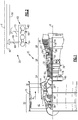
- FIG. 1 schematically illustrates a gas turbine engine 20.
- the gas turbine engine 20 is disclosed herein as a two-spool turbofan that generally incorporates a fan section 22, a compressor section 24, a combustor section 26 and a turbine section 28.
- Alternative engines might include an augmenter section (not shown) among other systems or features.
- the fan section 22 drives air along a bypass flow path B in a bypass duct defined within a nacelle 15, while the compressor section 24 drives air along a core flow path C for compression and communication into the combustor section 26 then expansion through the turbine section 28.
- the exemplary gas turbine engine 20 generally includes a low speed spool 30 and a high speed spool 32 mounted for rotation about an engine central longitudinal axis X relative to an engine static structure 36 via several bearing systems 38. It should be understood that various bearing systems 38 at various locations may alternatively or additionally be provided, and the location of bearing systems 38 may be varied as appropriate to the application.
- the low speed spool 30 generally includes an inner shaft 40 that interconnects a fan 42, a first (or low) pressure compressor 44 and a first (or low) pressure turbine 46.
- the inner shaft 40 is connected to the fan 42 through a speed change mechanism, which in exemplary gas turbine engine 20 is illustrated as a geared architecture 48 to drive the fan 42 at a lower speed than the low speed spool 30.
- the high speed spool 32 includes an outer shaft 50 that interconnects a second (or high) pressure compressor 52 and a second (or high) pressure turbine 54.
- a combustor 56 is arranged in the exemplary gas turbine engine 20 between the high pressure compressor 52 and the high pressure turbine 54.
- a mid-turbine frame 57 of the engine static structure 36 is arranged generally between the high pressure turbine 54 and the low pressure turbine 46.
- the mid-turbine frame 57 further supports bearing systems 38 in the turbine section 28.
- the inner shaft 40 and the outer shaft 50 are concentric and rotate via bearing systems 38 about the engine central longitudinal axis X which is collinear with their longitudinal axes.
- the core airflow is compressed by the low pressure compressor 44 then the high pressure compressor 52, mixed and burned with fuel in the combustor 56, then expanded over the high pressure turbine 54 and low pressure turbine 46.
- the mid-turbine frame 57 includes airfoils 59 which are in the core airflow path C.
- the turbines 46, 54 rotationally drive the respective low speed spool 30 and high speed spool 32 in response to the expansion.
- gear system 48 may be located aft of combustor section 26 or even aft of turbine section 28, and fan section 22 may be positioned forward or aft of the location of gear system 48.
- the gas turbine engine 20 in one example is a high-bypass geared aircraft engine.
- the gas turbine engine 20 bypass ratio is greater than about six, with an example embodiment being greater than about ten
- the geared architecture 48 is an epicyclic gear train, such as a planetary gear system or other gear system, with a gear reduction ratio of greater than about 2.3 and the low pressure turbine 46 has a pressure ratio that is greater than about five.
- the gas turbine engine 20 bypass ratio is greater than about ten
- the fan diameter is significantly larger than that of the low pressure compressor 44
- the low pressure turbine 46 has a pressure ratio that is greater than about five.
- Low pressure turbine 46 pressure ratio is pressure measured prior to inlet of low pressure turbine 46 as related to the pressure at the outlet of the low pressure turbine 46 prior to an exhaust nozzle.
- the geared architecture 48 may be an epicycle gear train, such as a planetary gear system or other gear system, with a gear reduction ratio of greater than about 2.3:1. It should be understood, however, that the above parameters are only exemplary of one embodiment of a geared architecture engine and that the present invention is applicable to other gas turbine engines including direct drive turbofans.
- the fan section 22 of the gas turbine engine 20 is designed for a particular flight condition - typically cruise at about 0.8 Mach and about 35,000 feet (10,668 meters).
- the flight condition of 0.8 Mach and 35,000 ft (10,668 meters), with the engine at its best fuel consumption - also known as "bucket cruise Thrust Specific Fuel Consumption ('TSFC')" - is the industry standard parameter of lbm of fuel being burned divided by lbf of thrust the engine produces at that minimum point.
- "Low fan pressure ratio” is the pressure ratio across the fan blade alone, without a Fan Exit Guide Vane (“FEGV”) system.
- the low fan pressure ratio as disclosed herein according to one non-limiting embodiment is less than about 1.45.
- the "Low corrected fan tip speed" as disclosed herein according to one non-limiting embodiment is less than about 1150 ft / second (350.5 meters/second).
- the gas turbine engine 20 includes an accessory drive gearbox 60, or gearbox, that is rotationally driven by both the inner and outer shafts 40, 50.
- the accessory drive gearbox 60 includes a housing 62 within which first and second sets of gears 64, 66 are arranged.
- a first towershaft 68 extends through a strut 69 to interconnect the inner shaft 40 to the first set of gears 64.
- the first towershaft 68 can drive the first set of gears 64 through a layshaft, for example.
- a second towershaft 70 extends through a strut 71 to interconnect the outer shaft 50 to the second set of gears 66.
- the second towershaft 70 can drive the second set of gears 66 through a layshaft, for example.
- the first towershaft 68 could interconnect to the outer shaft 50 and the second towershaft 70 could interconnect to the inner shaft 40.
- the exemplary accessory drive gearbox 60 is described as incorporating the first and second sets of gears 64, 66, another example of the accessory drive gearbox 60 could include a set of gears driven by the first towershaft 68, without any gears being driven by the second towershaft 70. Yet another example of the accessory drive gearbox 60 could include a set of gears driven by the second towershaft 70, without any gears being driven by the first towershaft 68.
- a portion of the exemplary accessory drive gearbox 60 utilizes the first set of gears 64 to rotatably drive to rotatably drive an oil pump 80 and a transmission 84.
- An output shaft 88 from the transmission 84 drives an electric machine 92 and a hydraulic pump 96.
- the first towershaft 68 is driven by the inner shaft 40 to rotatably drive the first set of gears 64.
- the oil pump 80 is driven by the first towershaft 68 such that the rotational speed of the oil pump 80 varies linearly with the rotational speed of the first towershaft 68.
- the electric machine 92 and the hydraulic pump 96 are driven by the first towershaft 68, but through the transmission 84.
- the transmission 84 can step up or step down the rotational speed of the output shaft 88 from the transmission 84 relative to the rotational speed of the first towershaft 68. This permits the electric machine 92 and the hydraulic pump 96 to rotate relative to the first towershaft 68 at different ratios.
- oil pump 80 is directly driven by the first towershaft 68, other examples could include directly driving other accessories instead of, or in addition to, the oil pump 80 with the first towershaft 68.
- the electric machine 92 and the hydraulic pump 96 are driven by the output shaft 88 from the transmission 84, other examples could include driving other accessories instead of, or in addition to, the electric machine 92 or the hydraulic pump 96.
- the inner shaft 40 can experience a greater range of rotational speeds that the outer shaft 50. That is, the speed excursion for the inner shaft 40 can be higher than the speed excursion for the outer shaft 50.
- the inner shaft 40 can operate at speed excursions of up to 80% during operation of the gas turbine engine 20, whereas the outer shaft 50 can operate at speed excursions of up to 30% during operation of the gas turbine engine 20.
- the first towershaft 68 is geared to the inner shaft 40, such that the rotational speed of the first towershaft 68 and the first set of gears 64 varies linearly with the rotational speed of the inner shaft 40.
- the second towershaft 70 is geared to the outer shaft 50 so that the rotational speed of the second towershaft 70 and the second set of gears 66 varies linearly with the rotational speed of the outer shaft 50.
- the transmission 84 addresses issues associated with rotating the electric machine 92 and the hydraulic pump 96 with a rotatable input from the first towershaft 68 from the inner shaft 40.
- the transmission 84 can vary the rotational speed of the output shaft 88 relative to the rotational speed of the first towershaft 68 to rotate the electric machine 92 and hydraulic pump 96 at a desired rotational speed.
- An electronic engine control (EEC) 100 can control the transmission 84 so that the output shaft 88 is rotated at a desired speed or within a desired range.
- the transmission 84 is a traction drive or multispeed transmission.
- the transmission 84 lacks a plurality of fixed gear ratios and instead can change through a continuous range of effective gear ratios.
- the transmission 84 can be considered a continuously variable transmission (CVT) in some examples.
- the electric machine 92 is an integrated drive generator or a variable frequency generator that receives a rotational input to generate power utilized by components of the gas turbine engine 20.
- the transmission 84 permits operating the electric machine 92 to be driven in a narrower rpm range while still being driven by rotation of the inner shaft 40 and the first towershaft 68.
- the hydraulic pump 96 generally moves hydraulic fluid needed to move components of an air frame to which the gas turbine engine 20 is mounted.
- the transmission 84 permits operating the hydraulic pump 96 to be driven in a narrower rpm range while still being driven by rotation of the inner shaft 40 and the first towershaft 68.
- the oil pump 80 is driven at a fixed ratio relative to the speed of the first towershaft 68. That is, the transmission 84 transitioning between its continuous range of effective gear ratios does not substantially change a ratio of rotational speeds between the first towershaft 68 and the oil pump 80.
- the oil pump 80 is dedicated to supplying oil to the number 1 bearing systems 38', which incorporates thrust bearings directly supporting the inner shaft 40.
- the thrust bearings are tapered bearings in some examples.
- the rotational speed of the first towershaft 68 increases when the rotational speed of the inner shaft 40 increases.
- the inner shaft 40 may require additional lubrication, such as oil, directed to bearing systems 38 supporting the inner shaft 40 when the rotational speed of the inner shaft 40 increases.
- the increased lubrication demands due to increasing the rotational speed of the inner shaft 40 are met by increasing the rotational input speed to the oil pump 82.
- the amount of oil moved to the number 1 bearing system 38' varies linearly with the rotational speed of the inner shaft 40. If the oil pump 82 were instead varying linearly with the rotational speed of the outer shaft 50, the oil pump 82 may move more oil than is required for lubrication. The excess oil would need to recirculated, or accommodated in some other way, which results in losses.
- An added feature of coupling rotation of the oil pump 82 with rotation of the inner shaft 40 is that the inner shaft 40 spins with the fan 42.
- the oil pump 80 can continue to pump oil lubricating the bearings associated with the inner shaft 40, including bearing system 38 supporting a fan rotor of the fan 42 and the geared architecture 48 ( Figure 1 ). If the oil pump 80 were decoupled from rotation with the inner shaft 40, another pump or an electronic pump could be required to move oil to lubricate the fan 42 when windmilling.
- features of the some of the disclosed examples include driving accessory components of an accessory gearbox using a traction drive transmission. This can provide an idle thrust reduction, a reduction in EGT and mission fuel burn.
Landscapes
- Engineering & Computer Science (AREA)
- General Engineering & Computer Science (AREA)
- Mechanical Engineering (AREA)
- Chemical & Material Sciences (AREA)
- Combustion & Propulsion (AREA)
- General Details Of Gearings (AREA)
Applications Claiming Priority (1)
| Application Number | Priority Date | Filing Date | Title |
|---|---|---|---|
| US201662435342P | 2016-12-16 | 2016-12-16 |
Publications (2)
| Publication Number | Publication Date |
|---|---|
| EP3336334A1 true EP3336334A1 (fr) | 2018-06-20 |
| EP3336334B1 EP3336334B1 (fr) | 2021-05-26 |
Family
ID=60781621
Family Applications (1)
| Application Number | Title | Priority Date | Filing Date |
|---|---|---|---|
| EP17207856.0A Active EP3336334B1 (fr) | 2016-12-16 | 2017-12-15 | Transmission à entraînement par traction pour boîte de vitesses d'accessoire de moteur à turbine à gaz |
Country Status (2)
| Country | Link |
|---|---|
| US (1) | US20180171815A1 (fr) |
| EP (1) | EP3336334B1 (fr) |
Cited By (1)
| Publication number | Priority date | Publication date | Assignee | Title |
|---|---|---|---|---|
| EP3696391A1 (fr) * | 2019-02-13 | 2020-08-19 | United Technologies Corporation | Boîte de vitesse accessoire pour moteur à turbine à gaz à transmission variable |
Families Citing this family (14)
| Publication number | Priority date | Publication date | Assignee | Title |
|---|---|---|---|---|
| US10883424B2 (en) | 2016-07-19 | 2021-01-05 | Pratt & Whitney Canada Corp. | Multi-spool gas turbine engine architecture |
| US11415063B2 (en) | 2016-09-15 | 2022-08-16 | Pratt & Whitney Canada Corp. | Reverse-flow gas turbine engine |
| US11035293B2 (en) | 2016-09-15 | 2021-06-15 | Pratt & Whitney Canada Corp. | Reverse flow gas turbine engine with offset RGB |
| US10465611B2 (en) | 2016-09-15 | 2019-11-05 | Pratt & Whitney Canada Corp. | Reverse flow multi-spool gas turbine engine with aft-end accessory gearbox drivingly connected to both high pressure spool and low pressure spool |
| US10815899B2 (en) | 2016-11-15 | 2020-10-27 | Pratt & Whitney Canada Corp. | Gas turbine engine accessories arrangement |
| US10808624B2 (en) | 2017-02-09 | 2020-10-20 | Pratt & Whitney Canada Corp. | Turbine rotor with low over-speed requirements |
| US10746188B2 (en) | 2017-03-14 | 2020-08-18 | Pratt & Whitney Canada Corp. | Inter-shaft bearing connected to a compressor boost system |
| EP4339440A3 (fr) | 2018-08-08 | 2024-05-22 | Pratt & Whitney Canada Corp. | Système et procédé multimoteur |
| US10634064B1 (en) | 2018-10-11 | 2020-04-28 | United Technologies Corporation | Accessory gearbox with superposition gearbox |
| US12276230B2 (en) * | 2019-03-20 | 2025-04-15 | Rtx Corporation | Variable transmission driven fuel pump for a gas turbine engine |
| US20200340411A1 (en) * | 2019-04-29 | 2020-10-29 | Hamilton Sundstrand Corporation | Fuel delivery system for gas turbine engine |
| DE102019120462A1 (de) * | 2019-07-29 | 2021-02-04 | Rolls-Royce Deutschland Ltd & Co Kg | Hilfsgerätegetriebe eines Gasturbinentriebwerkes und Gasturbinentriebwerk |
| CN118499453A (zh) | 2023-02-16 | 2024-08-16 | 通用电气阿维奥有限责任公司 | 齿轮箱组件 |
| US12372032B1 (en) * | 2024-08-01 | 2025-07-29 | Rtx Corporation | Gas turbine engine with controlled return of fuel to power accessories and retrofitting method |
Citations (4)
| Publication number | Priority date | Publication date | Assignee | Title |
|---|---|---|---|---|
| EP1031717A2 (fr) * | 1999-02-25 | 2000-08-30 | Rolls-Royce Plc | Turbine à gaz |
| EP1106870A2 (fr) * | 1999-12-01 | 2001-06-13 | Kawasaki Jukogyo Kabushiki Kaisha | Méthode et appareil d'entraínement d'une génératrice d'avion à vitesse constante |
| EP2320067A2 (fr) * | 2009-11-04 | 2011-05-11 | Kawasaki Jukogyo Kabushiki Kaisha | Alternateur-démarreur d'avion |
| EP2584174A2 (fr) * | 2011-10-21 | 2013-04-24 | United Technologies Corporation | Fonctionnement à eolienne d'un moteur à turbine à gaz |
Family Cites Families (4)
| Publication number | Priority date | Publication date | Assignee | Title |
|---|---|---|---|---|
| US5845483A (en) * | 1996-04-10 | 1998-12-08 | General Electric Company | Windmill engine starting system with fluid driven motor and pump |
| US9062611B2 (en) * | 2011-10-19 | 2015-06-23 | United Technologies Corporation | Split accessory drive system |
| US8572943B1 (en) * | 2012-05-31 | 2013-11-05 | United Technologies Corporation | Fundamental gear system architecture |
| EP2801707B1 (fr) * | 2013-05-10 | 2017-07-05 | Safran Aero Boosters SA | Circuit de lubrification de turbomachine avec vanne anti-siphon pour windmilling |
-
2017
- 2017-11-30 US US15/827,132 patent/US20180171815A1/en not_active Abandoned
- 2017-12-15 EP EP17207856.0A patent/EP3336334B1/fr active Active
Patent Citations (4)
| Publication number | Priority date | Publication date | Assignee | Title |
|---|---|---|---|---|
| EP1031717A2 (fr) * | 1999-02-25 | 2000-08-30 | Rolls-Royce Plc | Turbine à gaz |
| EP1106870A2 (fr) * | 1999-12-01 | 2001-06-13 | Kawasaki Jukogyo Kabushiki Kaisha | Méthode et appareil d'entraínement d'une génératrice d'avion à vitesse constante |
| EP2320067A2 (fr) * | 2009-11-04 | 2011-05-11 | Kawasaki Jukogyo Kabushiki Kaisha | Alternateur-démarreur d'avion |
| EP2584174A2 (fr) * | 2011-10-21 | 2013-04-24 | United Technologies Corporation | Fonctionnement à eolienne d'un moteur à turbine à gaz |
Cited By (2)
| Publication number | Priority date | Publication date | Assignee | Title |
|---|---|---|---|---|
| EP3696391A1 (fr) * | 2019-02-13 | 2020-08-19 | United Technologies Corporation | Boîte de vitesse accessoire pour moteur à turbine à gaz à transmission variable |
| US11346427B2 (en) | 2019-02-13 | 2022-05-31 | Raytheon Technologies Corporation | Accessory gearbox for gas turbine engine with variable transmission |
Also Published As
| Publication number | Publication date |
|---|---|
| EP3336334B1 (fr) | 2021-05-26 |
| US20180171815A1 (en) | 2018-06-21 |
Similar Documents
| Publication | Publication Date | Title |
|---|---|---|
| EP3336334B1 (fr) | Transmission à entraînement par traction pour boîte de vitesses d'accessoire de moteur à turbine à gaz | |
| US11846237B2 (en) | Gas turbine engine with intercooled cooling air and dual towershaft accessory gearbox | |
| EP3354881B1 (fr) | Boîte d'engrenages d'accessoires de moteur à turbine à gaz à deux arbres d'entraînement et ensemble générateur de démarreur | |
| EP3063387B1 (fr) | Pompe à huile auxiliaire pour organe de démultiplication de moteur à turbine à gaz | |
| EP3032074A1 (fr) | Boîtier d'accessoires avec deux arbres d'entraînement pour turbine à gaz | |
| US10605173B2 (en) | High and low spool accessory gearbox drive | |
| EP3431738B1 (fr) | Entraînement tangentiel pour accessoires de moteur de turbine à gaz | |
| EP2959129B1 (fr) | Étage auxiliaire de pompe d'alimentation en lubrifiant formé d'un seul tenant avec un étage principal de pompe à lubrifiant | |
| WO2015047577A1 (fr) | Moteur à turbine à gaz avec système de lubrification fractionné | |
| EP4215737B1 (fr) | Extraction de puissance à double bobine avec boîte de vitesses à superposition | |
| US10590853B2 (en) | Gas turbine engine dual towershaft accessory gearbox assembly with a transmission | |
| WO2014052558A1 (fr) | Turboventilateur à engrenages comprenant des boîtiers d'accessoires montés sur le ventilateur et le cœur | |
| US10590852B2 (en) | Gas turbine engine dual towershaft accessory gearbox assembly with a transmission | |
| WO2015094539A1 (fr) | Palier de transfert pour réacteur à double flux à réducteur | |
| EP4074952B1 (fr) | Turbine à gaz à engrenage avec assistance par pompe à éjecteur de vidange d'huile |
Legal Events
| Date | Code | Title | Description |
|---|---|---|---|
| PUAI | Public reference made under article 153(3) epc to a published international application that has entered the european phase |
Free format text: ORIGINAL CODE: 0009012 |
|
| STAA | Information on the status of an ep patent application or granted ep patent |
Free format text: STATUS: THE APPLICATION HAS BEEN PUBLISHED |
|
| AK | Designated contracting states |
Kind code of ref document: A1 Designated state(s): AL AT BE BG CH CY CZ DE DK EE ES FI FR GB GR HR HU IE IS IT LI LT LU LV MC MK MT NL NO PL PT RO RS SE SI SK SM TR |
|
| AX | Request for extension of the european patent |
Extension state: BA ME |
|
| STAA | Information on the status of an ep patent application or granted ep patent |
Free format text: STATUS: REQUEST FOR EXAMINATION WAS MADE |
|
| 17P | Request for examination filed |
Effective date: 20181220 |
|
| RBV | Designated contracting states (corrected) |
Designated state(s): AL AT BE BG CH CY CZ DE DK EE ES FI FR GB GR HR HU IE IS IT LI LT LU LV MC MK MT NL NO PL PT RO RS SE SI SK SM TR |
|
| REG | Reference to a national code |
Ref country code: DE Ref legal event code: R079 Ref document number: 602017039188 Country of ref document: DE Free format text: PREVIOUS MAIN CLASS: F02C0007320000 Ipc: F01D0025200000 |
|
| RIC1 | Information provided on ipc code assigned before grant |
Ipc: F01D 15/10 20060101ALI20201029BHEP Ipc: F01D 25/20 20060101AFI20201029BHEP Ipc: F02C 7/32 20060101ALI20201029BHEP Ipc: F02C 7/36 20060101ALI20201029BHEP |
|
| GRAP | Despatch of communication of intention to grant a patent |
Free format text: ORIGINAL CODE: EPIDOSNIGR1 |
|
| STAA | Information on the status of an ep patent application or granted ep patent |
Free format text: STATUS: GRANT OF PATENT IS INTENDED |
|
| RIN1 | Information on inventor provided before grant (corrected) |
Inventor name: MCCUNE, MICHAEL E. Inventor name: MERRY, BRIAN Inventor name: SUCIU, GABRIEL L. Inventor name: SHERIDAN, WILLIAM G. |
|
| INTG | Intention to grant announced |
Effective date: 20201209 |
|
| RAP1 | Party data changed (applicant data changed or rights of an application transferred) |
Owner name: RAYTHEON TECHNOLOGIES CORPORATION |
|
| GRAS | Grant fee paid |
Free format text: ORIGINAL CODE: EPIDOSNIGR3 |
|
| GRAA | (expected) grant |
Free format text: ORIGINAL CODE: 0009210 |
|
| STAA | Information on the status of an ep patent application or granted ep patent |
Free format text: STATUS: THE PATENT HAS BEEN GRANTED |
|
| AK | Designated contracting states |
Kind code of ref document: B1 Designated state(s): AL AT BE BG CH CY CZ DE DK EE ES FI FR GB GR HR HU IE IS IT LI LT LU LV MC MK MT NL NO PL PT RO RS SE SI SK SM TR |
|
| REG | Reference to a national code |
Ref country code: GB Ref legal event code: FG4D |
|
| REG | Reference to a national code |
Ref country code: CH Ref legal event code: EP |
|
| REG | Reference to a national code |
Ref country code: DE Ref legal event code: R096 Ref document number: 602017039188 Country of ref document: DE |
|
| REG | Reference to a national code |
Ref country code: AT Ref legal event code: REF Ref document number: 1396418 Country of ref document: AT Kind code of ref document: T Effective date: 20210615 |
|
| REG | Reference to a national code |
Ref country code: IE Ref legal event code: FG4D |
|
| REG | Reference to a national code |
Ref country code: LT Ref legal event code: MG9D |
|
| REG | Reference to a national code |
Ref country code: AT Ref legal event code: MK05 Ref document number: 1396418 Country of ref document: AT Kind code of ref document: T Effective date: 20210526 |
|
| PG25 | Lapsed in a contracting state [announced via postgrant information from national office to epo] |
Ref country code: AT Free format text: LAPSE BECAUSE OF FAILURE TO SUBMIT A TRANSLATION OF THE DESCRIPTION OR TO PAY THE FEE WITHIN THE PRESCRIBED TIME-LIMIT Effective date: 20210526 Ref country code: BG Free format text: LAPSE BECAUSE OF FAILURE TO SUBMIT A TRANSLATION OF THE DESCRIPTION OR TO PAY THE FEE WITHIN THE PRESCRIBED TIME-LIMIT Effective date: 20210826 Ref country code: HR Free format text: LAPSE BECAUSE OF FAILURE TO SUBMIT A TRANSLATION OF THE DESCRIPTION OR TO PAY THE FEE WITHIN THE PRESCRIBED TIME-LIMIT Effective date: 20210526 Ref country code: FI Free format text: LAPSE BECAUSE OF FAILURE TO SUBMIT A TRANSLATION OF THE DESCRIPTION OR TO PAY THE FEE WITHIN THE PRESCRIBED TIME-LIMIT Effective date: 20210526 Ref country code: LT Free format text: LAPSE BECAUSE OF FAILURE TO SUBMIT A TRANSLATION OF THE DESCRIPTION OR TO PAY THE FEE WITHIN THE PRESCRIBED TIME-LIMIT Effective date: 20210526 |
|
| REG | Reference to a national code |
Ref country code: NL Ref legal event code: MP Effective date: 20210526 |
|
| PG25 | Lapsed in a contracting state [announced via postgrant information from national office to epo] |
Ref country code: RS Free format text: LAPSE BECAUSE OF FAILURE TO SUBMIT A TRANSLATION OF THE DESCRIPTION OR TO PAY THE FEE WITHIN THE PRESCRIBED TIME-LIMIT Effective date: 20210526 Ref country code: SE Free format text: LAPSE BECAUSE OF FAILURE TO SUBMIT A TRANSLATION OF THE DESCRIPTION OR TO PAY THE FEE WITHIN THE PRESCRIBED TIME-LIMIT Effective date: 20210526 Ref country code: PT Free format text: LAPSE BECAUSE OF FAILURE TO SUBMIT A TRANSLATION OF THE DESCRIPTION OR TO PAY THE FEE WITHIN THE PRESCRIBED TIME-LIMIT Effective date: 20210927 Ref country code: NO Free format text: LAPSE BECAUSE OF FAILURE TO SUBMIT A TRANSLATION OF THE DESCRIPTION OR TO PAY THE FEE WITHIN THE PRESCRIBED TIME-LIMIT Effective date: 20210826 Ref country code: PL Free format text: LAPSE BECAUSE OF FAILURE TO SUBMIT A TRANSLATION OF THE DESCRIPTION OR TO PAY THE FEE WITHIN THE PRESCRIBED TIME-LIMIT Effective date: 20210526 Ref country code: LV Free format text: LAPSE BECAUSE OF FAILURE TO SUBMIT A TRANSLATION OF THE DESCRIPTION OR TO PAY THE FEE WITHIN THE PRESCRIBED TIME-LIMIT Effective date: 20210526 Ref country code: GR Free format text: LAPSE BECAUSE OF FAILURE TO SUBMIT A TRANSLATION OF THE DESCRIPTION OR TO PAY THE FEE WITHIN THE PRESCRIBED TIME-LIMIT Effective date: 20210827 Ref country code: IS Free format text: LAPSE BECAUSE OF FAILURE TO SUBMIT A TRANSLATION OF THE DESCRIPTION OR TO PAY THE FEE WITHIN THE PRESCRIBED TIME-LIMIT Effective date: 20210926 |
|
| PG25 | Lapsed in a contracting state [announced via postgrant information from national office to epo] |
Ref country code: NL Free format text: LAPSE BECAUSE OF FAILURE TO SUBMIT A TRANSLATION OF THE DESCRIPTION OR TO PAY THE FEE WITHIN THE PRESCRIBED TIME-LIMIT Effective date: 20210526 |
|
| PG25 | Lapsed in a contracting state [announced via postgrant information from national office to epo] |
Ref country code: RO Free format text: LAPSE BECAUSE OF FAILURE TO SUBMIT A TRANSLATION OF THE DESCRIPTION OR TO PAY THE FEE WITHIN THE PRESCRIBED TIME-LIMIT Effective date: 20210526 Ref country code: ES Free format text: LAPSE BECAUSE OF FAILURE TO SUBMIT A TRANSLATION OF THE DESCRIPTION OR TO PAY THE FEE WITHIN THE PRESCRIBED TIME-LIMIT Effective date: 20210526 Ref country code: EE Free format text: LAPSE BECAUSE OF FAILURE TO SUBMIT A TRANSLATION OF THE DESCRIPTION OR TO PAY THE FEE WITHIN THE PRESCRIBED TIME-LIMIT Effective date: 20210526 Ref country code: CZ Free format text: LAPSE BECAUSE OF FAILURE TO SUBMIT A TRANSLATION OF THE DESCRIPTION OR TO PAY THE FEE WITHIN THE PRESCRIBED TIME-LIMIT Effective date: 20210526 Ref country code: DK Free format text: LAPSE BECAUSE OF FAILURE TO SUBMIT A TRANSLATION OF THE DESCRIPTION OR TO PAY THE FEE WITHIN THE PRESCRIBED TIME-LIMIT Effective date: 20210526 Ref country code: SK Free format text: LAPSE BECAUSE OF FAILURE TO SUBMIT A TRANSLATION OF THE DESCRIPTION OR TO PAY THE FEE WITHIN THE PRESCRIBED TIME-LIMIT Effective date: 20210526 Ref country code: SM Free format text: LAPSE BECAUSE OF FAILURE TO SUBMIT A TRANSLATION OF THE DESCRIPTION OR TO PAY THE FEE WITHIN THE PRESCRIBED TIME-LIMIT Effective date: 20210526 |
|
| REG | Reference to a national code |
Ref country code: DE Ref legal event code: R097 Ref document number: 602017039188 Country of ref document: DE |
|
| PLBE | No opposition filed within time limit |
Free format text: ORIGINAL CODE: 0009261 |
|
| STAA | Information on the status of an ep patent application or granted ep patent |
Free format text: STATUS: NO OPPOSITION FILED WITHIN TIME LIMIT |
|
| 26N | No opposition filed |
Effective date: 20220301 |
|
| PG25 | Lapsed in a contracting state [announced via postgrant information from national office to epo] |
Ref country code: IS Free format text: LAPSE BECAUSE OF FAILURE TO SUBMIT A TRANSLATION OF THE DESCRIPTION OR TO PAY THE FEE WITHIN THE PRESCRIBED TIME-LIMIT Effective date: 20210926 Ref country code: AL Free format text: LAPSE BECAUSE OF FAILURE TO SUBMIT A TRANSLATION OF THE DESCRIPTION OR TO PAY THE FEE WITHIN THE PRESCRIBED TIME-LIMIT Effective date: 20210526 |
|
| PG25 | Lapsed in a contracting state [announced via postgrant information from national office to epo] |
Ref country code: MC Free format text: LAPSE BECAUSE OF FAILURE TO SUBMIT A TRANSLATION OF THE DESCRIPTION OR TO PAY THE FEE WITHIN THE PRESCRIBED TIME-LIMIT Effective date: 20210526 Ref country code: IT Free format text: LAPSE BECAUSE OF FAILURE TO SUBMIT A TRANSLATION OF THE DESCRIPTION OR TO PAY THE FEE WITHIN THE PRESCRIBED TIME-LIMIT Effective date: 20210526 |
|
| REG | Reference to a national code |
Ref country code: CH Ref legal event code: PL |
|
| REG | Reference to a national code |
Ref country code: BE Ref legal event code: MM Effective date: 20211231 |
|
| PG25 | Lapsed in a contracting state [announced via postgrant information from national office to epo] |
Ref country code: LU Free format text: LAPSE BECAUSE OF NON-PAYMENT OF DUE FEES Effective date: 20211215 Ref country code: IE Free format text: LAPSE BECAUSE OF NON-PAYMENT OF DUE FEES Effective date: 20211215 |
|
| PG25 | Lapsed in a contracting state [announced via postgrant information from national office to epo] |
Ref country code: BE Free format text: LAPSE BECAUSE OF NON-PAYMENT OF DUE FEES Effective date: 20211231 |
|
| PG25 | Lapsed in a contracting state [announced via postgrant information from national office to epo] |
Ref country code: LI Free format text: LAPSE BECAUSE OF NON-PAYMENT OF DUE FEES Effective date: 20211231 Ref country code: CH Free format text: LAPSE BECAUSE OF NON-PAYMENT OF DUE FEES Effective date: 20211231 |
|
| PG25 | Lapsed in a contracting state [announced via postgrant information from national office to epo] |
Ref country code: HU Free format text: LAPSE BECAUSE OF FAILURE TO SUBMIT A TRANSLATION OF THE DESCRIPTION OR TO PAY THE FEE WITHIN THE PRESCRIBED TIME-LIMIT; INVALID AB INITIO Effective date: 20171215 |
|
| P01 | Opt-out of the competence of the unified patent court (upc) registered |
Effective date: 20230520 |
|
| PG25 | Lapsed in a contracting state [announced via postgrant information from national office to epo] |
Ref country code: CY Free format text: LAPSE BECAUSE OF FAILURE TO SUBMIT A TRANSLATION OF THE DESCRIPTION OR TO PAY THE FEE WITHIN THE PRESCRIBED TIME-LIMIT Effective date: 20210526 |
|
| PG25 | Lapsed in a contracting state [announced via postgrant information from national office to epo] |
Ref country code: MK Free format text: LAPSE BECAUSE OF FAILURE TO SUBMIT A TRANSLATION OF THE DESCRIPTION OR TO PAY THE FEE WITHIN THE PRESCRIBED TIME-LIMIT Effective date: 20210526 |
|
| PG25 | Lapsed in a contracting state [announced via postgrant information from national office to epo] |
Ref country code: TR Free format text: LAPSE BECAUSE OF FAILURE TO SUBMIT A TRANSLATION OF THE DESCRIPTION OR TO PAY THE FEE WITHIN THE PRESCRIBED TIME-LIMIT Effective date: 20210526 |
|
| PG25 | Lapsed in a contracting state [announced via postgrant information from national office to epo] |
Ref country code: MT Free format text: LAPSE BECAUSE OF FAILURE TO SUBMIT A TRANSLATION OF THE DESCRIPTION OR TO PAY THE FEE WITHIN THE PRESCRIBED TIME-LIMIT Effective date: 20210526 |
|
| REG | Reference to a national code |
Ref country code: DE Ref legal event code: R081 Ref document number: 602017039188 Country of ref document: DE Owner name: RTX CORPORATION (N.D.GES.D. STAATES DELAWARE),, US Free format text: FORMER OWNER: RAYTHEON TECHNOLOGIES CORPORATION, FARMINGTON, CT, US |
|
| PGFP | Annual fee paid to national office [announced via postgrant information from national office to epo] |
Ref country code: DE Payment date: 20251126 Year of fee payment: 9 |
|
| PGFP | Annual fee paid to national office [announced via postgrant information from national office to epo] |
Ref country code: GB Payment date: 20251119 Year of fee payment: 9 |
|
| PGFP | Annual fee paid to national office [announced via postgrant information from national office to epo] |
Ref country code: FR Payment date: 20251120 Year of fee payment: 9 |