EP3336854B1 - Four de fusion à plasma à grilles de décharge latérales - Google Patents
Four de fusion à plasma à grilles de décharge latérales Download PDFInfo
- Publication number
- EP3336854B1 EP3336854B1 EP15901044.6A EP15901044A EP3336854B1 EP 3336854 B1 EP3336854 B1 EP 3336854B1 EP 15901044 A EP15901044 A EP 15901044A EP 3336854 B1 EP3336854 B1 EP 3336854B1
- Authority
- EP
- European Patent Office
- Prior art keywords
- discharge
- lateral
- furnace body
- molten material
- furnace
- Prior art date
- Legal status (The legal status is an assumption and is not a legal conclusion. Google has not performed a legal analysis and makes no representation as to the accuracy of the status listed.)
- Active
Links
Images


Classifications
-
- F—MECHANICAL ENGINEERING; LIGHTING; HEATING; WEAPONS; BLASTING
- F27—FURNACES; KILNS; OVENS; RETORTS
- F27D—DETAILS OR ACCESSORIES OF FURNACES, KILNS, OVENS OR RETORTS, IN SO FAR AS THEY ARE OF KINDS OCCURRING IN MORE THAN ONE KIND OF FURNACE
- F27D3/00—Charging; Discharging; Manipulation of charge
- F27D3/14—Charging or discharging liquid or molten material
-
- F—MECHANICAL ENGINEERING; LIGHTING; HEATING; WEAPONS; BLASTING
- F23—COMBUSTION APPARATUS; COMBUSTION PROCESSES
- F23G—CREMATION FURNACES; CONSUMING WASTE PRODUCTS BY COMBUSTION
- F23G5/00—Incineration of waste; Incinerator constructions; Details, accessories or control therefor
- F23G5/08—Incineration of waste; Incinerator constructions; Details, accessories or control therefor having supplementary heating
- F23G5/085—High-temperature heating means, e.g. plasma, for partly melting the waste
-
- F—MECHANICAL ENGINEERING; LIGHTING; HEATING; WEAPONS; BLASTING
- F27—FURNACES; KILNS; OVENS; RETORTS
- F27B—FURNACES, KILNS, OVENS OR RETORTS IN GENERAL; OPEN SINTERING OR LIKE APPARATUS
- F27B17/00—Furnaces of a kind not covered by any of groups F27B1/00 - F27B15/00
- F27B17/0016—Chamber type furnaces
-
- F—MECHANICAL ENGINEERING; LIGHTING; HEATING; WEAPONS; BLASTING
- F27—FURNACES; KILNS; OVENS; RETORTS
- F27B—FURNACES, KILNS, OVENS OR RETORTS IN GENERAL; OPEN SINTERING OR LIKE APPARATUS
- F27B3/00—Hearth-type furnaces, e.g. of reverberatory type; Electric arc furnaces ; Tank furnaces
- F27B3/10—Details, accessories or equipment, e.g. dust-collectors, specially adapted for hearth-type furnaces
- F27B3/105—Slag chamber
-
- F—MECHANICAL ENGINEERING; LIGHTING; HEATING; WEAPONS; BLASTING
- F27—FURNACES; KILNS; OVENS; RETORTS
- F27B—FURNACES, KILNS, OVENS OR RETORTS IN GENERAL; OPEN SINTERING OR LIKE APPARATUS
- F27B3/00—Hearth-type furnaces, e.g. of reverberatory type; Electric arc furnaces ; Tank furnaces
- F27B3/10—Details, accessories or equipment, e.g. dust-collectors, specially adapted for hearth-type furnaces
- F27B3/19—Arrangements of devices for discharging
-
- F—MECHANICAL ENGINEERING; LIGHTING; HEATING; WEAPONS; BLASTING
- F27—FURNACES; KILNS; OVENS; RETORTS
- F27D—DETAILS OR ACCESSORIES OF FURNACES, KILNS, OVENS OR RETORTS, IN SO FAR AS THEY ARE OF KINDS OCCURRING IN MORE THAN ONE KIND OF FURNACE
- F27D99/00—Subject matter not provided for in other groups of this subclass
- F27D99/0001—Heating elements or systems
- F27D99/0006—Electric heating elements or system
-
- G—PHYSICS
- G21—NUCLEAR PHYSICS; NUCLEAR ENGINEERING
- G21F—PROTECTION AGAINST X-RADIATION, GAMMA RADIATION, CORPUSCULAR RADIATION OR PARTICLE BOMBARDMENT; TREATING RADIOACTIVELY CONTAMINATED MATERIAL; DECONTAMINATION ARRANGEMENTS THEREFOR
- G21F9/00—Treating radioactively contaminated material; Decontamination arrangements therefor
- G21F9/28—Treating solids
- G21F9/30—Processing
-
- F—MECHANICAL ENGINEERING; LIGHTING; HEATING; WEAPONS; BLASTING
- F27—FURNACES; KILNS; OVENS; RETORTS
- F27B—FURNACES, KILNS, OVENS OR RETORTS IN GENERAL; OPEN SINTERING OR LIKE APPARATUS
- F27B17/00—Furnaces of a kind not covered by any of groups F27B1/00 - F27B15/00
- F27B17/0016—Chamber type furnaces
- F27B2017/0091—Series of chambers, e.g. associated in their use
-
- F—MECHANICAL ENGINEERING; LIGHTING; HEATING; WEAPONS; BLASTING
- F27—FURNACES; KILNS; OVENS; RETORTS
- F27D—DETAILS OR ACCESSORIES OF FURNACES, KILNS, OVENS OR RETORTS, IN SO FAR AS THEY ARE OF KINDS OCCURRING IN MORE THAN ONE KIND OF FURNACE
- F27D99/00—Subject matter not provided for in other groups of this subclass
- F27D99/0001—Heating elements or systems
- F27D99/0006—Electric heating elements or system
- F27D2099/0015—Induction heating
-
- F—MECHANICAL ENGINEERING; LIGHTING; HEATING; WEAPONS; BLASTING
- F27—FURNACES; KILNS; OVENS; RETORTS
- F27D—DETAILS OR ACCESSORIES OF FURNACES, KILNS, OVENS OR RETORTS, IN SO FAR AS THEY ARE OF KINDS OCCURRING IN MORE THAN ONE KIND OF FURNACE
- F27D99/00—Subject matter not provided for in other groups of this subclass
- F27D99/0001—Heating elements or systems
- F27D99/0006—Electric heating elements or system
- F27D2099/0031—Plasma-torch heating
Definitions
- the present invention relates to a plasma furnace having a lateral discharge gate capable of efficiently discharging molten material in a low viscosity state.
- a method of discharging molten material is a method of discharging molten material by tilting a furnace or a method of discharging molten material after further heating the molten material using an induction heating device around an outlet of the furnace.
- the plasma furnace of Tsuruga nuclear power plant in Japan or Zwilag in Switzerland manufactured by Retech, USA uses a method of discharging through an outlet positioned the bottom.
- an outlet positioned at the center of the bottom of the cone type furnace is heated by an induction heating method and then molten material is discharged.
- a method of heating and discharging the molten material by using a heating torch as an additional heat source near the outlet is used.
- the molten material at a high temperature over 1,600°C is discharged to the outlet of the furnace, its viscosity rapidly becomes higher than 100 poise due to the decrease in the temperature of the molten material so that the outlet may become clogged by solidification at the outlet.
- the present invention has been made to solve the above problems occurring in the prior art, and the purpose of the present invention is to provide a plasma furnace capable of effectively discharging molten material in a low viscosity state and separating and discharging different kinds of molten material according to their specific gravity.
- a drum type waste input apparatus for a plasma furnace is as defined in claim 1, with preferred embodiments being set out in the dependent claims.
- the plasma furnace comprises: a furnace body; and a heating portion, wherein the furnace body comprises a melt discharge portion formed through a lower portion of the melting chamber provided for accommodating molten material; and at least two lateral discharge gates provided at different heights capable of discharging molten material, and wherein the heating portion is capable of heating the lateral discharge gate.
- the melt discharge portion comprises a dam type discharge gate provided to protrude on the lower portion of the melting chamber to discharge the molten material above a predefined height.
- the dam type discharge gate further comprises an induction heater.
- the lateral discharge gate is moved up and down with respect to the furnace body to open and close a discharge flow path.
- the plasma furnace further comprises a discharge chamber provided on the lateral portion of the furnace body for accommodating the discharged melt along the lateral discharge gate and having an outlet at the lower portion.
- the discharge chamber may further comprise a window for observing the inside, and may further comprise a door that can be opened and closed.
- the plasma furnace of the present invention comprises a melt discharge portion formed through a lower portion of a melting chamber and at least two lateral discharge gates provided on the side of the melting chamber at different heights for discharging the molten material. Accordingly, the clogging phenomenon at the melt discharge portion in the lower portion of the melting chamber due to the molten material in a high viscosity state can be solved and also the different kinds of melts can be separated and discharged according to the specific gravity.
- first and/or second etc. may be used to describe various components, but the components are not limited to the terms. The terms may be referred only for the purpose of distinguishing one component from another component.
- first component may also be referred to as a second component to the extent not departing from the scope of the invention in accordance with the claims likewise, the second component may also be referred to as a first component.
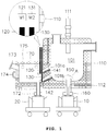
- the plasma furnace of the present invention comprises a furnace body 110; and a heating portion 141, 142 capable heating a lateral discharge gate 120, 130, wherein the furnace body comprises a melting chamber 101 for accommodating molten material, and two lateral discharge gates 120, 130 capable of discharging molten material at different heights on the side of the melting chamber 101.
- the furnace body 110 may be made using a material with a high thermal stability such as heat-resistant bricks, and a cooling channel 112 is formed in the inside of the furnace body 110. Accordingly, the outer surface of the furnace body 110 can be cooled and maintained at a proper temperature below 60 °C by circulation of cooling water.
- the furnace body 110 provides melting heat for melting the introduced waste by an installed plasma torch 111.
- the plasma torch 111 is installed at the upper end of the melting chamber 101 of the furnace body 110 and a dual plasma torch capable of transferred or non-transferred operation may be provided. Electrodes (not shown) for transferred operation may be provided at the lower portion of the melting chamber, and the melting efficiency can be maximized by using the Joule's heat and torch frame temperature and arc heat.
- a melt discharge portion is provided in the lower portion of the furnace body 110, and in particular, the melt discharge portion is provided by a dam-type discharge gate 150, and preferably further includes an induction heating type heater.
- a first clamp 160 may be provided at the lower end of the dam-type discharge gate 150 so as to be detachably coupled to a first mold apparatus 10.
- the first clamp 160 may be connected to the first mold apparatus 10 with a hermetic seal, Accordingly, when the molten material is discharged into the first mold apparatus 10, the outside air cannot flow into the inside of the furnace, and the atmosphere inside the furnace can be maintained.
- the first clamp 160 may be provided with a packing member such as a gasket or a synthetic rubber so that the first clamp 160 can be assembled with the first mold apparatus 10 in an airtight state.
- a cooling circuit may be provided to have the cooling water circulated to the first clamp 160 or its periphery so as to prevent degradation of the packing member due to a high temperature.
- the dam-type discharge gate 150 is formed to protrude from the bottom surface of the furnace body 110 by a predetermined height, h or more and may include an induction coil 151 of a cylindrical shape provided to surround the lower outlet 150a, and an exhaust tube 152, that is, an electric conductor for indirect induction heating fixed inside the induction coil 151.
- the molten material in the melting chamber 101 is completely discharged through the dam-type discharge gate 150, the molten material under a predetermined height (h) remains in the melting chamber 101 at all times.
- the inner wall of the melting chamber 101 is prevented from being directly exposed to a high temperature by the high-temperature plasma generated in the plasma torch 111 in the preheating process.
- the molten material becomes a solid in a high viscosity state to close the lower outlet 150a.
- the solid becomes thin to be discharged to the outside through the lower outlet 150a by its own weight.
- the melt discharge portion provided at the lower portion of the furnace body 110 may be used for discharging a metal material having a large specific gravity among the molten material or for discharging the entire molten material.
- the furnace body 110 is provided with two lateral discharge gates 120, 130 for discharging the molten material at different heights on the side of the melting chamber 101, and the heating portion 141, 142 capable of heating the lateral discharge gates 120, 130 is further included.
- Each lateral discharge gate 120, 130 is provided with a motor-operated or hydraulic drive unit 121, 131 to open and close each discharge flow path 101a, 101b by a vertical movement in the furnace body 110.
- Each discharge flow path 101a, 101b is formed with a predetermined slope through the furnace body 110 so that the molten material can be easily discharged to the outside by its own weight.
- a heating portion 141, 142 is provided adjacent to the discharge flow path 101a, 101b to maintain the discharged molten material at a melting temperature (1600°C) or higher.
- the heating portion 141, 142 may be provided as a metal or non-metal heater and may be formed as a wire or a plane depending on the size and length of the discharge flow path 101a, 101b. On the other hand, it can be provided by an induction heating-type heat source as another embodiment of the heating portion.
- each discharge flow path 101a, 101b it is exemplified that a heating element is provided in each discharge flow path 101a, 101b.
- the two discharge flow paths 101a, 101b may be heated by one common heating element.
- a discharge chamber 170 provided at the side of the furnace body 110 may be further comprised to accommodate the molten material discharged from each lateral discharge gate 120, 130.
- the discharge chamber 170 may be an enclosed structure integrated with the furnace body 110 or may be a detachable structure with the furnace body 110. Meanwhile, when the discharge chamber 170 is provided as a detachable structure with the furnace body 110, a hermetic member may be added between the discharge chamber 170 and the furnace body 110 to maintain a hermetic seal.
- the discharge chamber 170 is provided with a slag outlet 171 at a lower portion thereof and a second clamp 172 at a lower end of the slag outlet 171 to which the second mold apparatus 20 is detachably coupled.
- the second clamp 172 is connected to the second mold apparatus 20 with a hermetic seal. Accordingly, when the molten material, slag is discharged into the second mold apparatus 20, outside air cannot flow into the discharge chamber and the atmosphere inside the furnace can be maintained.
- the second clamp 172 may be provided with a packing member such as a gasket or a synthetic rubber so that the second clamp 172 can be assembled with the second mold apparatus 20 in an airtight state.
- a cooling circuit may be provided to have the cooling water circulated to the second clamp 172 or the periphery thereof so as to prevent degradation of the packing member due to a high temperature.
- the discharge chamber 170 may be provided with an observation window 173 for observing the discharge gate 120, 130 and may be provided with a surveillance camera (not shown) capable of capturing an image signal.
- the discharge chamber 170 may be provided with a door 174 that can be opened and closed at the front thereof so as to be able to collect a sample when the molten material is discharged.
- a heating means 175 may be provided so as to control the temperature inside the discharge chamber 170.
- Such a heating means 175 may be provided by molybdenum disilicide, MOSi 2 , which is effective as a heating element even at a high temperature of 1,500°C or higher.
- the lateral discharge gate 120, 130 is provided outside the furnace body 110 to be opened and closed.
- the lateral discharge gate may be provided inside the furnace body or in the melting chamber to discharge the molten material.
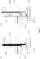
- FIG. 4(a) (b) shows a lateral discharge gate of the plasma furnace according to other embodiments.
- two lateral discharge gates 220, 230 are inserted through the lateral wall of the furnace body 210 so as to move up and down to open and close the discharge flow path 201a, 201b.
- two lateral discharge gates 320, 330 can be provided on the inner lateral wall of the furnace body 310 to control the discharge of molten material from the melting chamber 301 into the discharge flow path 301a, 301b.
- the lateral discharge gate can have a variety of layouts, and preferably is located outside the furnace body.
- two lateral discharge gates 120, 130 are provided outside the furnace body, by which maintenance of the lateral discharge gate 120, 130 can be performed more easily than the case where lateral discharge gates are inserted through the lateral wall of the furnace body.
- the possibility of design interference with the cooling channel 112 provided in the furnace body 110 can be eliminated.
Landscapes
- Engineering & Computer Science (AREA)
- General Engineering & Computer Science (AREA)
- Mechanical Engineering (AREA)
- Physics & Mathematics (AREA)
- High Energy & Nuclear Physics (AREA)
- Plasma & Fusion (AREA)
- Furnace Details (AREA)
- Vertical, Hearth, Or Arc Furnaces (AREA)
- Gasification And Melting Of Waste (AREA)
- Waste-Gas Treatment And Other Accessory Devices For Furnaces (AREA)
- Furnace Charging Or Discharging (AREA)
Claims (6)
- Four à plasma comprenant :un corps de four (110) comprenant une chambre de fusion (101) prévue pour abriter du matériau fondu, une section de décharge de coulée formée à travers une partie inférieure de la chambre de fusion (101) et au moins deux grilles de décharge latérales (120,130) prévues à différentes hauteurs et capables de décharger du matériau fondu ;une section de chauffage (141,142) prévue pour chauffer le parcours d'écoulement de décharge (101a, 101b)une chambre de décharge (170) prévue sur la section latérale du corps de four (110) pour abriter la coulée déchargée le long des grilles de décharge latérales (120,130) et comportant une sortie (171) à la partie inférieure ; etun moyen de chauffage (175) prévu pour commander la température à l'intérieur de la chambre de décharge (170) ;
les grilles de décharge latérales (120,130) étant insérées à travers une paroi latérale du corps de four (110) ou prévues sur une paroi latérale interne du corps de four (110) de manière à monter et descendre pour ouvrir et fermer les parcours d'écoulement de décharge respectifs (101a, 101b) avec les grilles de décharge latérales (120,130) - Four à plasma selon la revendication 1,
dans lequel la section de décharge de coulée comprend une grille de décharge de type barrage (150) prévue pour saillir sur la partie inférieure de la chambre de fusion (101) pour décharger le matériau fondu au-dessus d'une hauteur prédéfinie. - Four à plasma selon la revendication 2,
dans lequel la grille de décharge de type barrage (150) comprend en outre un système de chauffage à induction. - Four à plasma selon la revendication 1,
dans lequel la grille de décharge latérale (120,130) est montée et descendue par rapport au corps de four (110) pour ouvrir et fermer un parcours d'écoulement de décharge (101a, 101b). - Four à plasma selon la revendication 1,
dans lequel la chambre de décharge (170) comprend en outre une fenêtre (173) pour observer l'intérieur du four. - Four à plasma selon la revendication 1 ou 5,
dans lequel la chambre de décharge (170) comprend en outre une porte (174) qui peut être ouverte et fermée.
Applications Claiming Priority (2)
| Application Number | Priority Date | Filing Date | Title |
|---|---|---|---|
| KR1020150114045A KR101617167B1 (ko) | 2015-08-12 | 2015-08-12 | 측면 배출게이트가 구비된 플라즈마 용융로 |
| PCT/KR2015/008580 WO2017026562A1 (fr) | 2015-08-12 | 2015-08-18 | Four de fusion à plasma à grilles de décharge latérales |
Publications (3)
| Publication Number | Publication Date |
|---|---|
| EP3336854A1 EP3336854A1 (fr) | 2018-06-20 |
| EP3336854A4 EP3336854A4 (fr) | 2018-12-19 |
| EP3336854B1 true EP3336854B1 (fr) | 2021-01-20 |
Family
ID=56022679
Family Applications (1)
| Application Number | Title | Priority Date | Filing Date |
|---|---|---|---|
| EP15901044.6A Active EP3336854B1 (fr) | 2015-08-12 | 2015-08-18 | Four de fusion à plasma à grilles de décharge latérales |
Country Status (6)
| Country | Link |
|---|---|
| US (1) | US10914523B2 (fr) |
| EP (1) | EP3336854B1 (fr) |
| JP (2) | JP2018521294A (fr) |
| KR (1) | KR101617167B1 (fr) |
| CN (1) | CN107924728A (fr) |
| WO (1) | WO2017026562A1 (fr) |
Families Citing this family (6)
| Publication number | Priority date | Publication date | Assignee | Title |
|---|---|---|---|---|
| KR101687660B1 (ko) * | 2016-07-28 | 2016-12-21 | 주식회사 트리플 | 중ㆍ저준위 방사성폐기물 처리를 위한 밀폐형 플라즈마 용융로 |
| KR101912722B1 (ko) * | 2016-11-29 | 2018-10-30 | 한국수력원자력 주식회사 | 유도가열 방식이 구비된 폐기물 처리장치 |
| KR102047313B1 (ko) | 2018-04-30 | 2019-11-21 | 한국수력원자력 주식회사 | 용융물 배출 시스템 |
| KR102122937B1 (ko) | 2018-04-30 | 2020-06-15 | 한국수력원자력 주식회사 | 용융로 배출구 가열장치 |
| CN108730986B (zh) * | 2018-07-12 | 2026-02-06 | 上海齐耀热能工程有限公司 | 固废处理装置 |
| JP2021170511A (ja) | 2020-04-17 | 2021-10-28 | 株式会社エンビジョンAescジャパン | 残容量推定装置、モデル生成装置、残容量推定方法、モデル生成方法、及びプログラム |
Family Cites Families (38)
| Publication number | Priority date | Publication date | Assignee | Title |
|---|---|---|---|---|
| US3744438A (en) * | 1968-12-24 | 1973-07-10 | Pyro Magnetics Corp | Incinerating |
| EP0096493B1 (fr) * | 1982-05-25 | 1987-08-19 | Johnson Matthey Public Limited Company | Four à arc à plasma |
| US4655437A (en) * | 1985-05-03 | 1987-04-07 | Huron Valley Steel Corp. | Apparatus for simultaneously separating volatile and non-volatile metals |
| CA1278431C (fr) * | 1985-09-26 | 1991-01-02 | Nicholas Adrian Barcza | Production thermique de magnesium |
| JPH0480514A (ja) * | 1990-07-24 | 1992-03-13 | Daido Steel Co Ltd | 溶融処理用アーク炉のベースメタル取出装置 |
| DE4024700A1 (de) | 1990-08-03 | 1992-02-06 | Telefunken Systemtechnik | Muellverarbeitungsanlage |
| JPH06502220A (ja) * | 1990-11-14 | 1994-03-10 | ミンプロック テクノロジー プロプライエタリー リミテッド | 亜鉛の直接的硫化発煙 |
| US5280757A (en) * | 1992-04-13 | 1994-01-25 | Carter George W | Municipal solid waste disposal process |
| US5579705A (en) * | 1993-03-08 | 1996-12-03 | Kabushiki Kaisha Kobe Seiko Sho | Plasma furnace and a method of operating the same |
| FR2710861B1 (fr) * | 1993-10-08 | 1995-11-03 | Commissariat Energie Atomique | Procédé d'incinération et de vitrification de déchets dans un creuset. |
| GB2298701B (en) | 1993-11-19 | 1998-07-01 | Phoenix Environmental Limited | System for converting solid waste material into environmentally safe products |
| US5673285A (en) * | 1994-06-27 | 1997-09-30 | Electro-Pyrolysis, Inc. | Concentric electrode DC arc systems and their use in processing waste materials |
| JP3037097B2 (ja) * | 1995-03-17 | 2000-04-24 | 日立造船株式会社 | 電気式灰溶融炉のメタル排出方法および装置 |
| US5690888A (en) * | 1995-06-07 | 1997-11-25 | Molten Metal Technologies, Inc. | Apparatus and method for tapping a reactor containing a molten fluid |
| KR200343807Y1 (ko) | 1998-12-30 | 2004-05-17 | 삼성중공업 주식회사 | 플라즈마 용융로 |
| KR100334439B1 (ko) | 1998-12-30 | 2002-08-28 | 삼성중공업 주식회사 | 플라즈마용융로슬래그배출장치 |
| JP2001050530A (ja) * | 1999-08-05 | 2001-02-23 | Nkk Corp | 塩類を含む焼却残渣の溶融処理方法及びその溶融炉 |
| KR100415801B1 (ko) | 2003-04-14 | 2004-01-24 | 주식회사 케이비 엔텍 | 폐기물의 용융방법 및 그 장치 |
| JP3860135B2 (ja) * | 2003-04-30 | 2006-12-20 | 株式会社メイチュー | 金属溶解炉 |
| US6971323B2 (en) * | 2004-03-19 | 2005-12-06 | Peat International, Inc. | Method and apparatus for treating waste |
| CN2869728Y (zh) * | 2005-11-15 | 2007-02-14 | 宁波金田铜业(集团)股份有限公司 | 有色金属熔炼、保温复合炉 |
| JP4949074B2 (ja) | 2007-02-23 | 2012-06-06 | 三菱重工環境・化学エンジニアリング株式会社 | プラズマ式溶融炉の運転制御方法及び装置 |
| ES2334870B1 (es) * | 2007-10-04 | 2011-01-03 | Consejo Superior De Investigaciones Cientificas | Horno de induccion modificado para la eliminacion de residuos siderurgicos con cinc con recuperacion de sus metales. |
| KR101032055B1 (ko) | 2008-11-26 | 2011-05-02 | 지에스플라텍 주식회사 | 플라즈마 토치 용융로의 용융물 출탕 장치 및 방법 |
| JP5391770B2 (ja) | 2009-03-25 | 2014-01-15 | Jfeエンジニアリング株式会社 | 廃棄物処理装置および廃棄物処理方法 |
| KR20110113223A (ko) | 2010-04-09 | 2011-10-17 | 정정철 | 플라즈마를 이용한 철 분진의 철괴 제조방법 |
| KR101188210B1 (ko) | 2010-08-03 | 2012-10-05 | 인하대학교 산학협력단 | 선점형 우선순위 기반의 이더넷 데이타 스케줄링 방법 및 이를 이용한 시스템 |
| JP2012132631A (ja) * | 2010-12-22 | 2012-07-12 | Tokai Konetsu Kogyo Co Ltd | 溶融炉 |
| KR20120128752A (ko) * | 2011-05-18 | 2012-11-28 | 주식회사 플라즈마 그린 테크놀러지 | 플라즈마를 이용한 방사성 폐기물 처리장치 및 처리방법 |
| KR101277817B1 (ko) * | 2011-09-30 | 2013-06-21 | 주식회사 서울엔지니어링 | 슬래그 배출 도어 제조 방법 |
| JP2013101088A (ja) | 2011-11-10 | 2013-05-23 | Ngk Insulators Ltd | 放射性廃棄物焼却炉および放射性廃棄物焼却処理方法 |
| KR101330970B1 (ko) * | 2011-11-29 | 2013-11-18 | 현대제철 주식회사 | 슬래그를 이용한 유가금속 회수 및 다기능성 골재의 제조 장치 |
| CN202350509U (zh) * | 2011-12-14 | 2012-07-25 | 北京建筑工程学院 | 近零污染物排放的天然气无焰催化燃烧炉窑 |
| SE537235C2 (sv) * | 2012-09-21 | 2015-03-10 | Valeas Recycling Ab | Förfarande och arrangemang för återvinning av förångningsbara ämnen ur en slagg medelst plasmainducerad förångning |
| KR101457368B1 (ko) * | 2013-10-04 | 2014-11-03 | 한국수력원자력 주식회사 | 용융물의 유도가열식 배출장치 및 방법 |
| CN103833035B (zh) * | 2014-03-06 | 2017-01-11 | 台州市一能科技有限公司 | 一种碳化硅的制备方法 |
| KR101418105B1 (ko) | 2014-04-24 | 2014-07-11 | 주식회사 플라즈마 그린 테크놀로지 | 무기성 폐자원을 이용한 암면 부산물 제조를 위한 플라즈마 토치형 용융장치 및 그 제조방법 |
| KR20240090634A (ko) * | 2015-08-07 | 2024-06-21 | 파이로제네시스 캐나다 인코퍼레이티드 | 실리카로부터 고순도 실리콘을 제조하는 방법 |
-
2015
- 2015-08-12 KR KR1020150114045A patent/KR101617167B1/ko active Active
- 2015-08-18 EP EP15901044.6A patent/EP3336854B1/fr active Active
- 2015-08-18 JP JP2018504290A patent/JP2018521294A/ja active Pending
- 2015-08-18 WO PCT/KR2015/008580 patent/WO2017026562A1/fr not_active Ceased
- 2015-08-18 US US15/750,278 patent/US10914523B2/en active Active
- 2015-08-18 CN CN201580082296.9A patent/CN107924728A/zh active Pending
-
2019
- 2019-12-26 JP JP2019236022A patent/JP2020073844A/ja active Pending
Non-Patent Citations (1)
| Title |
|---|
| None * |
Also Published As
| Publication number | Publication date |
|---|---|
| EP3336854A1 (fr) | 2018-06-20 |
| KR101617167B1 (ko) | 2016-05-03 |
| JP2020073844A (ja) | 2020-05-14 |
| CN107924728A (zh) | 2018-04-17 |
| US20180363982A1 (en) | 2018-12-20 |
| WO2017026562A1 (fr) | 2017-02-16 |
| EP3336854A4 (fr) | 2018-12-19 |
| JP2018521294A (ja) | 2018-08-02 |
| US10914523B2 (en) | 2021-02-09 |
Similar Documents
| Publication | Publication Date | Title |
|---|---|---|
| EP3336854B1 (fr) | Four de fusion à plasma à grilles de décharge latérales | |
| JP3672942B2 (ja) | 冷却壁を有する融解炉で融解された材料の調節可能な流量での注ぎによる抽出用の装置 | |
| EP3099991B1 (fr) | Installation et procédé de fusion de matériaux métalliques | |
| EP3336855B1 (fr) | Four de fusion à plasma | |
| RU2420368C2 (ru) | Непрерывная разливка реакционно-способных металлов при использовании покрытия из стекла | |
| US10731923B2 (en) | Furnace for melting and treating metal and metallic waste and method therefor | |
| KR102048318B1 (ko) | 노 | |
| US20160091249A1 (en) | Crucibles for melting material and methods of transferring material therefrom | |
| CN215391537U (zh) | 熔融炉和放浆装置 | |
| KR102086142B1 (ko) | 고철 분리구조를 가진 알루미늄 용해로 | |
| KR20140042181A (ko) | 알루미늄 압축칩 덩어리를 침적 용해할 수 있는 용해로 | |
| EP3332043B1 (fr) | Système et procédé de gestion de laitier | |
| CN113560318A (zh) | 熔融炉和放浆装置 | |
| KR20180137681A (ko) | 질소냉각구조를 갖는 용탕배출장치 | |
| TR2023004620U5 (tr) | Dolayli gaz isitmali yolluk si̇stemi̇ | |
| JP2012132631A (ja) | 溶融炉 | |
| KR101665770B1 (ko) | 슬래그 배출 도어장치 | |
| JP2012233665A (ja) | 加熱用容器、局所加熱装置および加熱方法 | |
| CN204854333U (zh) | 金属熔化炉 | |
| SE177069C1 (fr) | ||
| JP3631973B2 (ja) | 廃棄物溶融炉 | |
| CN107842861A (zh) | 一种用于等离子熔融炉的自动式玻璃熔渣排放装置 | |
| US3780201A (en) | Plasma kiln | |
| KR200461167Y1 (ko) | 전기로 출강구의 홀더 고정장치 | |
| JP2005082417A (ja) | ガラス溶融炉 |
Legal Events
| Date | Code | Title | Description |
|---|---|---|---|
| STAA | Information on the status of an ep patent application or granted ep patent |
Free format text: STATUS: THE INTERNATIONAL PUBLICATION HAS BEEN MADE |
|
| PUAI | Public reference made under article 153(3) epc to a published international application that has entered the european phase |
Free format text: ORIGINAL CODE: 0009012 |
|
| STAA | Information on the status of an ep patent application or granted ep patent |
Free format text: STATUS: REQUEST FOR EXAMINATION WAS MADE |
|
| 17P | Request for examination filed |
Effective date: 20180312 |
|
| AK | Designated contracting states |
Kind code of ref document: A1 Designated state(s): AL AT BE BG CH CY CZ DE DK EE ES FI FR GB GR HR HU IE IS IT LI LT LU LV MC MK MT NL NO PL PT RO RS SE SI SK SM TR |
|
| AX | Request for extension of the european patent |
Extension state: BA ME |
|
| DAV | Request for validation of the european patent (deleted) | ||
| DAX | Request for extension of the european patent (deleted) | ||
| A4 | Supplementary search report drawn up and despatched |
Effective date: 20181119 |
|
| RIC1 | Information provided on ipc code assigned before grant |
Ipc: F27B 3/19 20060101ALI20181113BHEP Ipc: F27B 3/10 20060101ALI20181113BHEP Ipc: G21F 9/30 20060101AFI20181113BHEP Ipc: F27D 99/00 20100101ALI20181113BHEP Ipc: F27B 17/00 20060101ALI20181113BHEP Ipc: F23G 5/08 20060101ALI20181113BHEP |
|
| STAA | Information on the status of an ep patent application or granted ep patent |
Free format text: STATUS: EXAMINATION IS IN PROGRESS |
|
| 17Q | First examination report despatched |
Effective date: 20190724 |
|
| REG | Reference to a national code |
Ref country code: DE Ref legal event code: R079 Ref document number: 602015065110 Country of ref document: DE Free format text: PREVIOUS MAIN CLASS: G21F0009300000 Ipc: F27D0003140000 |
|
| GRAP | Despatch of communication of intention to grant a patent |
Free format text: ORIGINAL CODE: EPIDOSNIGR1 |
|
| STAA | Information on the status of an ep patent application or granted ep patent |
Free format text: STATUS: GRANT OF PATENT IS INTENDED |
|
| RIC1 | Information provided on ipc code assigned before grant |
Ipc: F27D 3/14 20060101AFI20200720BHEP Ipc: F27B 17/00 20060101ALI20200720BHEP Ipc: F27B 3/10 20060101ALI20200720BHEP Ipc: F27B 3/19 20060101ALI20200720BHEP Ipc: F27D 99/00 20100101ALI20200720BHEP Ipc: F23G 5/08 20060101ALI20200720BHEP Ipc: G21F 9/30 20060101ALI20200720BHEP |
|
| INTG | Intention to grant announced |
Effective date: 20200810 |
|
| RAP1 | Party data changed (applicant data changed or rights of an application transferred) |
Owner name: KOREA HYDRO & NUCLEAR POWER CO., LTD |
|
| GRAS | Grant fee paid |
Free format text: ORIGINAL CODE: EPIDOSNIGR3 |
|
| GRAA | (expected) grant |
Free format text: ORIGINAL CODE: 0009210 |
|
| STAA | Information on the status of an ep patent application or granted ep patent |
Free format text: STATUS: THE PATENT HAS BEEN GRANTED |
|
| AK | Designated contracting states |
Kind code of ref document: B1 Designated state(s): AL AT BE BG CH CY CZ DE DK EE ES FI FR GB GR HR HU IE IS IT LI LT LU LV MC MK MT NL NO PL PT RO RS SE SI SK SM TR |
|
| REG | Reference to a national code |
Ref country code: GB Ref legal event code: FG4D |
|
| REG | Reference to a national code |
Ref country code: CH Ref legal event code: EP |
|
| REG | Reference to a national code |
Ref country code: DE Ref legal event code: R096 Ref document number: 602015065110 Country of ref document: DE |
|
| REG | Reference to a national code |
Ref country code: AT Ref legal event code: REF Ref document number: 1356769 Country of ref document: AT Kind code of ref document: T Effective date: 20210215 |
|
| REG | Reference to a national code |
Ref country code: IE Ref legal event code: FG4D |
|
| REG | Reference to a national code |
Ref country code: NL Ref legal event code: MP Effective date: 20210120 |
|
| REG | Reference to a national code |
Ref country code: LT Ref legal event code: MG9D |
|
| REG | Reference to a national code |
Ref country code: AT Ref legal event code: MK05 Ref document number: 1356769 Country of ref document: AT Kind code of ref document: T Effective date: 20210120 |
|
| PG25 | Lapsed in a contracting state [announced via postgrant information from national office to epo] |
Ref country code: PT Free format text: LAPSE BECAUSE OF FAILURE TO SUBMIT A TRANSLATION OF THE DESCRIPTION OR TO PAY THE FEE WITHIN THE PRESCRIBED TIME-LIMIT Effective date: 20210520 Ref country code: NO Free format text: LAPSE BECAUSE OF FAILURE TO SUBMIT A TRANSLATION OF THE DESCRIPTION OR TO PAY THE FEE WITHIN THE PRESCRIBED TIME-LIMIT Effective date: 20210420 Ref country code: LT Free format text: LAPSE BECAUSE OF FAILURE TO SUBMIT A TRANSLATION OF THE DESCRIPTION OR TO PAY THE FEE WITHIN THE PRESCRIBED TIME-LIMIT Effective date: 20210120 Ref country code: GR Free format text: LAPSE BECAUSE OF FAILURE TO SUBMIT A TRANSLATION OF THE DESCRIPTION OR TO PAY THE FEE WITHIN THE PRESCRIBED TIME-LIMIT Effective date: 20210421 Ref country code: HR Free format text: LAPSE BECAUSE OF FAILURE TO SUBMIT A TRANSLATION OF THE DESCRIPTION OR TO PAY THE FEE WITHIN THE PRESCRIBED TIME-LIMIT Effective date: 20210120 Ref country code: FI Free format text: LAPSE BECAUSE OF FAILURE TO SUBMIT A TRANSLATION OF THE DESCRIPTION OR TO PAY THE FEE WITHIN THE PRESCRIBED TIME-LIMIT Effective date: 20210120 Ref country code: BG Free format text: LAPSE BECAUSE OF FAILURE TO SUBMIT A TRANSLATION OF THE DESCRIPTION OR TO PAY THE FEE WITHIN THE PRESCRIBED TIME-LIMIT Effective date: 20210420 |
|
| PG25 | Lapsed in a contracting state [announced via postgrant information from national office to epo] |
Ref country code: AT Free format text: LAPSE BECAUSE OF FAILURE TO SUBMIT A TRANSLATION OF THE DESCRIPTION OR TO PAY THE FEE WITHIN THE PRESCRIBED TIME-LIMIT Effective date: 20210120 Ref country code: PL Free format text: LAPSE BECAUSE OF FAILURE TO SUBMIT A TRANSLATION OF THE DESCRIPTION OR TO PAY THE FEE WITHIN THE PRESCRIBED TIME-LIMIT Effective date: 20210120 Ref country code: LV Free format text: LAPSE BECAUSE OF FAILURE TO SUBMIT A TRANSLATION OF THE DESCRIPTION OR TO PAY THE FEE WITHIN THE PRESCRIBED TIME-LIMIT Effective date: 20210120 Ref country code: RS Free format text: LAPSE BECAUSE OF FAILURE TO SUBMIT A TRANSLATION OF THE DESCRIPTION OR TO PAY THE FEE WITHIN THE PRESCRIBED TIME-LIMIT Effective date: 20210120 Ref country code: SE Free format text: LAPSE BECAUSE OF FAILURE TO SUBMIT A TRANSLATION OF THE DESCRIPTION OR TO PAY THE FEE WITHIN THE PRESCRIBED TIME-LIMIT Effective date: 20210120 |
|
| PG25 | Lapsed in a contracting state [announced via postgrant information from national office to epo] |
Ref country code: IS Free format text: LAPSE BECAUSE OF FAILURE TO SUBMIT A TRANSLATION OF THE DESCRIPTION OR TO PAY THE FEE WITHIN THE PRESCRIBED TIME-LIMIT Effective date: 20210520 |
|
| REG | Reference to a national code |
Ref country code: DE Ref legal event code: R097 Ref document number: 602015065110 Country of ref document: DE |
|
| PG25 | Lapsed in a contracting state [announced via postgrant information from national office to epo] |
Ref country code: EE Free format text: LAPSE BECAUSE OF FAILURE TO SUBMIT A TRANSLATION OF THE DESCRIPTION OR TO PAY THE FEE WITHIN THE PRESCRIBED TIME-LIMIT Effective date: 20210120 Ref country code: CZ Free format text: LAPSE BECAUSE OF FAILURE TO SUBMIT A TRANSLATION OF THE DESCRIPTION OR TO PAY THE FEE WITHIN THE PRESCRIBED TIME-LIMIT Effective date: 20210120 Ref country code: SM Free format text: LAPSE BECAUSE OF FAILURE TO SUBMIT A TRANSLATION OF THE DESCRIPTION OR TO PAY THE FEE WITHIN THE PRESCRIBED TIME-LIMIT Effective date: 20210120 |
|
| PLBE | No opposition filed within time limit |
Free format text: ORIGINAL CODE: 0009261 |
|
| STAA | Information on the status of an ep patent application or granted ep patent |
Free format text: STATUS: NO OPPOSITION FILED WITHIN TIME LIMIT |
|
| PG25 | Lapsed in a contracting state [announced via postgrant information from national office to epo] |
Ref country code: SK Free format text: LAPSE BECAUSE OF FAILURE TO SUBMIT A TRANSLATION OF THE DESCRIPTION OR TO PAY THE FEE WITHIN THE PRESCRIBED TIME-LIMIT Effective date: 20210120 Ref country code: DK Free format text: LAPSE BECAUSE OF FAILURE TO SUBMIT A TRANSLATION OF THE DESCRIPTION OR TO PAY THE FEE WITHIN THE PRESCRIBED TIME-LIMIT Effective date: 20210120 Ref country code: RO Free format text: LAPSE BECAUSE OF FAILURE TO SUBMIT A TRANSLATION OF THE DESCRIPTION OR TO PAY THE FEE WITHIN THE PRESCRIBED TIME-LIMIT Effective date: 20210120 |
|
| 26N | No opposition filed |
Effective date: 20211021 |
|
| PG25 | Lapsed in a contracting state [announced via postgrant information from national office to epo] |
Ref country code: ES Free format text: LAPSE BECAUSE OF FAILURE TO SUBMIT A TRANSLATION OF THE DESCRIPTION OR TO PAY THE FEE WITHIN THE PRESCRIBED TIME-LIMIT Effective date: 20210120 Ref country code: AL Free format text: LAPSE BECAUSE OF FAILURE TO SUBMIT A TRANSLATION OF THE DESCRIPTION OR TO PAY THE FEE WITHIN THE PRESCRIBED TIME-LIMIT Effective date: 20210120 |
|
| PG25 | Lapsed in a contracting state [announced via postgrant information from national office to epo] |
Ref country code: SI Free format text: LAPSE BECAUSE OF FAILURE TO SUBMIT A TRANSLATION OF THE DESCRIPTION OR TO PAY THE FEE WITHIN THE PRESCRIBED TIME-LIMIT Effective date: 20210120 |
|
| REG | Reference to a national code |
Ref country code: DE Ref legal event code: R119 Ref document number: 602015065110 Country of ref document: DE |
|
| PG25 | Lapsed in a contracting state [announced via postgrant information from national office to epo] |
Ref country code: MC Free format text: LAPSE BECAUSE OF FAILURE TO SUBMIT A TRANSLATION OF THE DESCRIPTION OR TO PAY THE FEE WITHIN THE PRESCRIBED TIME-LIMIT Effective date: 20210120 |
|
| REG | Reference to a national code |
Ref country code: BE Ref legal event code: MM Effective date: 20210831 |
|
| PG25 | Lapsed in a contracting state [announced via postgrant information from national office to epo] |
Ref country code: IT Free format text: LAPSE BECAUSE OF FAILURE TO SUBMIT A TRANSLATION OF THE DESCRIPTION OR TO PAY THE FEE WITHIN THE PRESCRIBED TIME-LIMIT Effective date: 20210120 |
|
| PG25 | Lapsed in a contracting state [announced via postgrant information from national office to epo] |
Ref country code: IS Free format text: LAPSE BECAUSE OF FAILURE TO SUBMIT A TRANSLATION OF THE DESCRIPTION OR TO PAY THE FEE WITHIN THE PRESCRIBED TIME-LIMIT Effective date: 20210520 Ref country code: LU Free format text: LAPSE BECAUSE OF NON-PAYMENT OF DUE FEES Effective date: 20210818 |
|
| PG25 | Lapsed in a contracting state [announced via postgrant information from national office to epo] |
Ref country code: IE Free format text: LAPSE BECAUSE OF NON-PAYMENT OF DUE FEES Effective date: 20210818 Ref country code: FR Free format text: LAPSE BECAUSE OF NON-PAYMENT OF DUE FEES Effective date: 20210831 Ref country code: DE Free format text: LAPSE BECAUSE OF NON-PAYMENT OF DUE FEES Effective date: 20220301 Ref country code: BE Free format text: LAPSE BECAUSE OF NON-PAYMENT OF DUE FEES Effective date: 20210831 |
|
| PG25 | Lapsed in a contracting state [announced via postgrant information from national office to epo] |
Ref country code: HU Free format text: LAPSE BECAUSE OF FAILURE TO SUBMIT A TRANSLATION OF THE DESCRIPTION OR TO PAY THE FEE WITHIN THE PRESCRIBED TIME-LIMIT; INVALID AB INITIO Effective date: 20150818 |
|
| PG25 | Lapsed in a contracting state [announced via postgrant information from national office to epo] |
Ref country code: NL Free format text: LAPSE BECAUSE OF NON-PAYMENT OF DUE FEES Effective date: 20210120 Ref country code: CY Free format text: LAPSE BECAUSE OF FAILURE TO SUBMIT A TRANSLATION OF THE DESCRIPTION OR TO PAY THE FEE WITHIN THE PRESCRIBED TIME-LIMIT Effective date: 20210120 |
|
| PG25 | Lapsed in a contracting state [announced via postgrant information from national office to epo] |
Ref country code: MK Free format text: LAPSE BECAUSE OF FAILURE TO SUBMIT A TRANSLATION OF THE DESCRIPTION OR TO PAY THE FEE WITHIN THE PRESCRIBED TIME-LIMIT Effective date: 20210120 |
|
| PG25 | Lapsed in a contracting state [announced via postgrant information from national office to epo] |
Ref country code: MT Free format text: LAPSE BECAUSE OF FAILURE TO SUBMIT A TRANSLATION OF THE DESCRIPTION OR TO PAY THE FEE WITHIN THE PRESCRIBED TIME-LIMIT Effective date: 20210120 |
|
| PGFP | Annual fee paid to national office [announced via postgrant information from national office to epo] |
Ref country code: GB Payment date: 20250828 Year of fee payment: 11 |
|
| PGFP | Annual fee paid to national office [announced via postgrant information from national office to epo] |
Ref country code: CH Payment date: 20250916 Year of fee payment: 11 |
|
| PG25 | Lapsed in a contracting state [announced via postgrant information from national office to epo] |
Ref country code: TR Free format text: LAPSE BECAUSE OF FAILURE TO SUBMIT A TRANSLATION OF THE DESCRIPTION OR TO PAY THE FEE WITHIN THE PRESCRIBED TIME-LIMIT Effective date: 20210120 |