EP3336855A1 - Four de fusion à plasma - Google Patents
Four de fusion à plasma Download PDFInfo
- Publication number
- EP3336855A1 EP3336855A1 EP15901058.6A EP15901058A EP3336855A1 EP 3336855 A1 EP3336855 A1 EP 3336855A1 EP 15901058 A EP15901058 A EP 15901058A EP 3336855 A1 EP3336855 A1 EP 3336855A1
- Authority
- EP
- European Patent Office
- Prior art keywords
- melting chamber
- plasma
- drum
- furnace body
- waste
- Prior art date
- Legal status (The legal status is an assumption and is not a legal conclusion. Google has not performed a legal analysis and makes no representation as to the accuracy of the status listed.)
- Granted
Links
Images


Classifications
-
- G—PHYSICS
- G21—NUCLEAR PHYSICS; NUCLEAR ENGINEERING
- G21F—PROTECTION AGAINST X-RADIATION, GAMMA RADIATION, CORPUSCULAR RADIATION OR PARTICLE BOMBARDMENT; TREATING RADIOACTIVELY CONTAMINATED MATERIAL; DECONTAMINATION ARRANGEMENTS THEREFOR
- G21F9/00—Treating radioactively contaminated material; Decontamination arrangements therefor
- G21F9/28—Treating solids
- G21F9/30—Processing
- G21F9/308—Processing by melting the waste
-
- F—MECHANICAL ENGINEERING; LIGHTING; HEATING; WEAPONS; BLASTING
- F27—FURNACES; KILNS; OVENS; RETORTS
- F27B—FURNACES, KILNS, OVENS OR RETORTS IN GENERAL; OPEN SINTERING OR LIKE APPARATUS
- F27B3/00—Hearth-type furnaces, e.g. of reverberatory type; Electric arc furnaces ; Tank furnaces
- F27B3/04—Hearth-type furnaces, e.g. of reverberatory type; Electric arc furnaces ; Tank furnaces of multiple-hearth type; of multiple-chamber type; Combinations of hearth-type furnaces
- F27B3/045—Multiple chambers, e.g. one of which is used for charging
-
- F—MECHANICAL ENGINEERING; LIGHTING; HEATING; WEAPONS; BLASTING
- F23—COMBUSTION APPARATUS; COMBUSTION PROCESSES
- F23G—CREMATION FURNACES; CONSUMING WASTE PRODUCTS BY COMBUSTION
- F23G5/00—Incineration of waste; Incinerator constructions; Details, accessories or control therefor
- F23G5/08—Incineration of waste; Incinerator constructions; Details, accessories or control therefor having supplementary heating
- F23G5/085—High-temperature heating means, e.g. plasma, for partly melting the waste
-
- F—MECHANICAL ENGINEERING; LIGHTING; HEATING; WEAPONS; BLASTING
- F23—COMBUSTION APPARATUS; COMBUSTION PROCESSES
- F23G—CREMATION FURNACES; CONSUMING WASTE PRODUCTS BY COMBUSTION
- F23G5/00—Incineration of waste; Incinerator constructions; Details, accessories or control therefor
- F23G5/44—Details; Accessories
- F23G5/442—Waste feed arrangements
- F23G5/444—Waste feed arrangements for solid waste
-
- F—MECHANICAL ENGINEERING; LIGHTING; HEATING; WEAPONS; BLASTING
- F23—COMBUSTION APPARATUS; COMBUSTION PROCESSES
- F23G—CREMATION FURNACES; CONSUMING WASTE PRODUCTS BY COMBUSTION
- F23G5/00—Incineration of waste; Incinerator constructions; Details, accessories or control therefor
- F23G5/44—Details; Accessories
- F23G5/442—Waste feed arrangements
- F23G5/448—Waste feed arrangements in which the waste is fed in containers or the like
-
- F—MECHANICAL ENGINEERING; LIGHTING; HEATING; WEAPONS; BLASTING
- F27—FURNACES; KILNS; OVENS; RETORTS
- F27B—FURNACES, KILNS, OVENS OR RETORTS IN GENERAL; OPEN SINTERING OR LIKE APPARATUS
- F27B17/00—Furnaces of a kind not covered by any of groups F27B1/00 - F27B15/00
-
- F—MECHANICAL ENGINEERING; LIGHTING; HEATING; WEAPONS; BLASTING
- F27—FURNACES; KILNS; OVENS; RETORTS
- F27D—DETAILS OR ACCESSORIES OF FURNACES, KILNS, OVENS OR RETORTS, IN SO FAR AS THEY ARE OF KINDS OCCURRING IN MORE THAN ONE KIND OF FURNACE
- F27D11/00—Arrangement of elements for electric heating in or on furnaces
- F27D11/08—Heating by electric discharge, e.g. arc discharge
-
- F—MECHANICAL ENGINEERING; LIGHTING; HEATING; WEAPONS; BLASTING
- F27—FURNACES; KILNS; OVENS; RETORTS
- F27D—DETAILS OR ACCESSORIES OF FURNACES, KILNS, OVENS OR RETORTS, IN SO FAR AS THEY ARE OF KINDS OCCURRING IN MORE THAN ONE KIND OF FURNACE
- F27D3/00—Charging; Discharging; Manipulation of charge
- F27D3/0025—Charging or loading melting furnaces with material in the solid state
- F27D3/003—Charging laterally, e.g. with a charging box
-
- F—MECHANICAL ENGINEERING; LIGHTING; HEATING; WEAPONS; BLASTING
- F27—FURNACES; KILNS; OVENS; RETORTS
- F27D—DETAILS OR ACCESSORIES OF FURNACES, KILNS, OVENS OR RETORTS, IN SO FAR AS THEY ARE OF KINDS OCCURRING IN MORE THAN ONE KIND OF FURNACE
- F27D3/00—Charging; Discharging; Manipulation of charge
- F27D3/14—Charging or discharging liquid or molten material
-
- G—PHYSICS
- G21—NUCLEAR PHYSICS; NUCLEAR ENGINEERING
- G21F—PROTECTION AGAINST X-RADIATION, GAMMA RADIATION, CORPUSCULAR RADIATION OR PARTICLE BOMBARDMENT; TREATING RADIOACTIVELY CONTAMINATED MATERIAL; DECONTAMINATION ARRANGEMENTS THEREFOR
- G21F9/00—Treating radioactively contaminated material; Decontamination arrangements therefor
- G21F9/28—Treating solids
- G21F9/30—Processing
-
- F—MECHANICAL ENGINEERING; LIGHTING; HEATING; WEAPONS; BLASTING
- F23—COMBUSTION APPARATUS; COMBUSTION PROCESSES
- F23G—CREMATION FURNACES; CONSUMING WASTE PRODUCTS BY COMBUSTION
- F23G2209/00—Specific waste
- F23G2209/18—Radioactive materials
-
- F—MECHANICAL ENGINEERING; LIGHTING; HEATING; WEAPONS; BLASTING
- F27—FURNACES; KILNS; OVENS; RETORTS
- F27D—DETAILS OR ACCESSORIES OF FURNACES, KILNS, OVENS OR RETORTS, IN SO FAR AS THEY ARE OF KINDS OCCURRING IN MORE THAN ONE KIND OF FURNACE
- F27D99/00—Subject matter not provided for in other groups of this subclass
- F27D99/0001—Heating elements or systems
- F27D99/0006—Electric heating elements or system
- F27D2099/0031—Plasma-torch heating
-
- Y—GENERAL TAGGING OF NEW TECHNOLOGICAL DEVELOPMENTS; GENERAL TAGGING OF CROSS-SECTIONAL TECHNOLOGIES SPANNING OVER SEVERAL SECTIONS OF THE IPC; TECHNICAL SUBJECTS COVERED BY FORMER USPC CROSS-REFERENCE ART COLLECTIONS [XRACs] AND DIGESTS
- Y02—TECHNOLOGIES OR APPLICATIONS FOR MITIGATION OR ADAPTATION AGAINST CLIMATE CHANGE
- Y02E—REDUCTION OF GREENHOUSE GAS [GHG] EMISSIONS, RELATED TO ENERGY GENERATION, TRANSMISSION OR DISTRIBUTION
- Y02E20/00—Combustion technologies with mitigation potential
- Y02E20/12—Heat utilisation in combustion or incineration of waste
Definitions
- the present invention relates to a plasma furnace which can efficiently treat various types of waste in large amounts.
- Radioactive wastes are classified as medium and low level waste, and high level waste including nuclear fuels used.
- Solid-state waste among the medium and low level radioactive wastes includes working clothes, gloves, overshoes, mops, and equipment replacement parts used in nuclear power plants and also includes sludge, concentrated waste fluid, ion exchange resin and the like generated secondarily by treatment such as coagulating precipitation, evaporation, and ion exchange for radioactive waste generated from liquid-state waste.
- reagent bottles, syringes, tubes and the like generated in the department of radiology of hospitals and industrial research institutes using a radioactive isotope.
- medium and low level radioactive waste is larger and more various than high level radioactive waste in generation amount and types.
- concentrated wastewater spent ion exchange resins, incineration ashes, and dried matter of concentrated waste solution which generally have a risk of scattering and spreading appropriate solidification medium is used to minimize leakage of radionuclides to the environment.
- Plasma furnaces are typically used to dispose of radioactive waste generated from nuclear power plants.
- the plasma furnace melts non-combustible materials such as metals and concrete, thereby reducing the volume.
- the treated waste can be stably stored in a radioactive waste repository for good.
- a plasma torch method When a plasma torch method is used for heating and melting a target material in a plasma furnace, a plasma torch has been utilized as a heat source in a top, side, or bottom of a furnace. In this case, the operation of the plasma torch may be limited depending on the structure of the furnace, and the generated plasma cannot maintain uniform heat in the furnace.
- the plasma torch inserted into the conventional plasma furnaces has a problem in that it needs to additionally include not only a main heating torch but a preheating torch for pre-heating target material in order to transfer sufficient heat into the furnace. Also, the plasma torch used in a large scale or large sized furnace has a disadvantage in terms of thermal efficiency, operation and maintenance of the torch since it is required to have more than a necessary amount of output.
- a large-sized furnace for directly processing a 200 L drum scale is used to increase the throughput of a target material, and a MW (mega watt) scale plasma torch is applied in consideration of the heat loss in the furnace and the torch.
- the present invention is intended to solve the above problems occurring in the prior arts, and provide a plasma furnace capable of efficiently processing various wastes.
- a plasma furnace according to the present invention in order to achieve the above purpose may comprise a furnace body and a mixed type plasma torch, wherein the furnace body comprises a melting chamber for accommodating a melt, an upper surface forming the upper portion of the melting chamber with a horizontal upper surface and an inclined upper surface having a slope with respect to the horizontal upper surface, a melt discharge portion formed through a bottom surface of the melting chamber for discharging molten material therethrough, and an input apparatus having a slope for inputting waste into the melting chamber, and wherein the mixed type plasma torch is provided on the inclined upper surface with a slope for generating melting heat in the melting chamber.
- the furnace body comprises a melting chamber for accommodating a melt, an upper surface forming the upper portion of the melting chamber with a horizontal upper surface and an inclined upper surface having a slope with respect to the horizontal upper surface, a melt discharge portion formed through a bottom surface of the melting chamber for discharging molten material therethrough, and an input apparatus having a slope for inputting waste into the melting chamber, and wherein the mixed type plasma torch
- the input apparatus and the inclined upper surface are provided in directions opposite to each other based on the furnace body.
- the input apparatus comprises a drum waiting portion provided with a slope to be charged with a waste drum; a pusher provided movable back and forth in the drum waiting portion for pushing the waste drum into the melting chamber; and a guide support for guiding the input of the waste drum by connecting the drum waiting portion and the lateral inlet of the furnace body.
- the input apparatus comprises a slide gate capable of opening and closing by sliding and provided on the upper portion of the drum waiting portion, and an input gate capable of opening and closing vertically by separating the drum waiting portion and the guide support spatially.
- the melt discharge portion includes a dam-type discharge gate provided to protrude from the lower portion of the melting chamber to discharge molten material above a predefined height.
- the dam-type discharge gate further comprises an induction heater.
- the furnace body further comprises at least two lateral discharge gates capable of discharging molten material at different heights on the side of the melting chamber; and a heating portion capable of heating the lateral discharge gate.
- it further comprises a discharge chamber which is provided on the lateral portion of the furnace body to accommodate the molten material discharged along the lateral discharge gate and have an outlet formed at the lower portion thereof.
- a plasma furnace according to the present invention is provided so that the upper portion of the melting chamber of the furnace body is formed and a part of the upper surface on which the plasma torch is installed is provided with a constant inclined surface. Accordingly, the torch in the melting chamber is smoothly operated, and plasma heat source generated by the torch can easily keep balanced up to the upper portion of the furnace.
- the present invention provides a structure in which nozzles of a mixed type plasma torch can be disposed in close proximity to an input apparatus for inputting a waste drum. Accordingly, there is no need to make a torch with an excessively large size in consideration of heat loss while stability of the torch can be maintained.
- the terms such as a first and/or second etc. may be used to describe various components, but the components are not limited to the terms. The terms may be referred only for the purpose of distinguishing one component from another component.
- the first component may also be referred to as a second component to the extent not departing from the scope of the invention in accordance with the concept of the present invention; likewise, the second component may also be referred to as a first component.
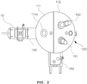
- the plasma furnace according to the first embodiment of the present invention comprises a furnace body 100 provided with a melting chamber 101 for accommodating molten material, and a plasma torch 191, 192 for generating melting heat in the melting chamber 101.
- the furnace body 100 may be made of a material having excellent heat resistance such as a heat resisting brick, and a metal material may be further used together for structural reinforcement.
- a cooling channel 102 is formed inside the furnace body 100 so that the outer surface of the furnace body 100 is maintained at an appropriate temperature (below 60°C) by circulation of cooling water.
- the melting chamber (101) is a structure capable of maintaining a negative pressure during operation and it is desirable to keep down dust generation and splashing of the molten material as much as possible.
- An upper input portion 111a is provided on the upper portion of the furnace body 100 and a separate input apparatus 120 is provided on the side portion so that waste can be input.
- the upper input portion 111a can be provided by a small-diameter (approximately 20 cm) input pipe and non-drum-shaped combustible waste can be input.
- the input apparatus 120 is installed at the lateral inlet 101a formed through the side of the furnace body 100 such that direct input of the waste drum 10 of 200L can be made.
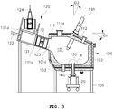
- the input apparatus 120 comprises a drum waiting portion 121 provided with a slope to be charged with a waste drum 10, a pusher 122 provided movable back and forth in the drum waiting portion for pushing the waste drum 10 into the melting chamber 101, and a guide support 123 for guiding the input of the waste drum 10 by connecting the drum waiting portion 121 and the lateral inlet 101a of the furnace body 100.
- the drum waiting portion 120 is provided to have a gentle slope in a range of approximately 20 to 45 degrees so that the waste drum 10 can be input along the inclined surface. Accordingly, the waste drum 10 is input into the melting chamber 101 along a gently inclined surface, thereby minimizing the impact that may be applied to the furnace body 100.
- the drum waiting portion 121 preferably comprises a slide gate 121a provided on the upper portion which is sliding openable; and an input gate 121b for spatially separating the drum waiting portion 121 and the guide support 123 and being vertically openable.
- the input apparatus 120 configured as aforementioned, when the slide gate 121a is opened, the waste drum 10 is positioned on the drum waiting portion 121 by the conveying crane 124. While the slide gate 121a is closed afterward, the inlet gate 121b is opened and the pusher 122 is operated for inputting the waste drum 10 on the drum waiting portion 121 into the melting chamber 101.
- the waste drum 10 can be charged as its original form into the melting chamber 101, and the opening and closing operations of the slide gate 121a and the inlet gate 121b can prevent the inflow of outside air and the gas generated in the melting chamber 101 from being discharged to the outside.
- the medium and low level wastes generated in nuclear power plants are stored in a closed 200L drum container.
- the wastes stored in drums are collected and stored in various forms, and the wastes comprise a variety of components having characteristic such as flammable, inorganic, etc. Therefore, it is difficult to separate and treat the radioactive waste stored in the 200L drum separately because of the concern on secondary contamination. Therefore, it is very important that a series of stabilization treatments such as waste input, crushing, combustion and melting, etc. should be continuously made in a single furnace. Accordingly, in the present invention, the waste drum moved from the repository can be introduced in its original form into the furnace, go through the melting treatment to the final disposal stage.
- the furnace body 100 has a cylindrical shape as a whole.
- the upper portion of the melting chamber 101 is formed by the upper surface 111, 112 comprising a horizontal upper surface 111, and an inclined upper surface 112 having a predefined angle ( ⁇ 1) to the rear and lower direction.
- the upper portion comprising the horizontal upper surface 111 and the inclined upper surface 112 may be provided in an integrated structure with the furnace body 100 or the upper portion 111, 112 may be provided as separable from the furnace body 100 such that the convenience of maintenance of the furnace body (100) can be improved.
- the horizontal upper surface 111 may be provided with an upper input portion 111a which is substantially horizontal with the ground and through which waste can be input.
- the inclined upper surface 111 has a slope at a predetermined angle ⁇ 1 in a down direction with respect to the horizontal upper surface 111.
- Plasma torches 191, 192 are provided on the upper surface 112 with a predefined angle ⁇ 2 with respect to the vertical direction.
- the horizontal upper surface 111 in the present invention does not mean that the horizontal upper surface 111 is horizontal with respect to the ground in an absolute sense, but may be provided substantially horizontally relative to the inclined upper surface 112. Accordingly, the horizontal upper surface 111 may have a slope within an angle range smaller than the slope angle ⁇ 1 of the inclined upper surface 112.
- Each of the plasma torches 191, 192 installed on the inclined upper surface 112 is provided with a separate guide member (not shown) and a driving source (not shown) so as to adjust the insertion length in the vertical direction for the transitional operation .
- the plasma torches 191, 192 are installed on the inclined upper surface 112 as described above, the flame generated in the plasma torch is uniformly distributed in the melting chamber 101. In addition, although the plasma torches keep a small range of vertical movement, stable output can be obtained.
- the slope angle ⁇ 1 of the inclined upper surface 112 and the slope angle ⁇ 2 of the plasma torches 191, 192 may be different from each other or may be the same.
- the inclined upper surface 112 is provided so as to be positioned opposite to the input apparatus 120 installed at one side of the furnace body 100 so that the nozzle at the lower end of the plasma torch 191, 192 can point to the input apparatus 120. Accordingly, sufficient melting heat can be provided to the position where the waste drum 10 is input and a separate plasma torch can be excluded for cutting and crushing the waste drum 10.
- the plasma torches 191, 192 in the present invention may be composed of a first plasma torch 191 and a second plasma torch 192 of a mixed type in which operations are performed independently of each other.
- the bottom electrode 103 is provided on the bottom surface of the furnace body 110 in parallel with the direction of the nozzle of the torch so that the transitional operation of the mixed type plasma torch can be performed and the bottom electrode 103 can be detachably attached to the furnace body 110.
- the other one can be on call as a spare. Accordingly, when the operation is not performed smoothly due to reasons such as a failure in supply of working gas to the torch in operation, the other torch on call can be operated.
- the operation control of these two plasma torches can be controlled automatically by interlocking with a separate torch monitoring device.
- the mixed type plasma torches 191, 192 installed on the inclined upper surface 112 are arranged in the vicinity of the charging direction of the waste drum 10 charged into the melting chamber 101 through the input apparatus 120 thereby, allowing a structure where a torch nozzle can be arranged.
- the waste drum 10 is charged into the melting chamber, the waste drum 10 is crushed through the preheating by the back and forth movement of the torch.
- torch stability can be maintained by moving the torch up and down quickly when pouring on the floor.
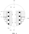
- a melt discharge portion is provided in the lower portion of the furnace body 100, and in particular, a melt discharge portion is provided by a dam-type discharge gate 130, and preferably further includes an induction heating type heater.
- a first clamp 140 may be provided at the lower end of the dam-type discharge gate 130 so as to be detachably coupled to a first mold apparatus 20.
- the first clamp 140 may be connected to the first mold apparatus 20 with a hermetic seal, Accordingly, when the molten material is discharged into the first mold apparatus 20, the outside air cannot flow into the inside of the furnace, and the atmosphere inside the furnace can be maintained.
- the first clamp 140 may be provided with a packing member such as a gasket or a synthetic rubber so that the first clamp 140 can be assembled with the first mold apparatus 20 in an airtight state.
- a cooling circuit may be provided to have the cooling water circulated to the first clamp 140 or its periphery so as to prevent degradation of the packing member due to a high temperature.
- the dam-type discharge gate 130 is formed to protrude from the bottom surface of the furnace body 100 by a predetermined height, h or more and may include an induction coil 132 provided to surround the lower outlet 131, and an exhaust tube 133, that is, an electric conductor for indirect induction heating provided inside the induction coil 132.
- the molten material in the melting chamber 101 is completely discharged through the dam-type discharge gate 130, the molten material under a predetermined height (h) remains in the melting chamber 101 at all times.
- the inner wall of the melting chamber 101 is prevented from being directly exposed to a high temperature by the high-temperature plasma generated in the plasma torch in the preheating process.
- the molten material becomes a solid in a high viscosity state to close the lower outlet 131.
- the solid becomes thin to be discharged to the outside through the lower outlet 131 by its own weight.
- the melt discharge portion provided at the lower portion of the furnace body 100 may be used for discharging a metal material having a large specific gravity among the molten material or for discharging the entire molten material.
- Reference numeral 105 denotes a lower support structure for supporting the furnace body 100.
- a discharge chamber 150 which accommodates the molten material discharged through a plurality of lateral discharge gates and is capable of discharging it may be further included in the side of the furnace body 100.
- the furnace body 100 is provided with lateral discharge gates 160, 170 for discharging the molten material at different heights on the sides of the melting chamber 101, and the heating portion 181, 182 capable of heating the lateral discharge gates 160 is further included.
- Each lateral discharge gate 160, 170 is provided with a motor-operated or hydraulic drive unit 161, 171 to open and close each discharge flow path 104a, 104b formed in the furnace body 100 by a vertical movement.
- Each discharge flow path 104a, 104b is formed with a predetermined slope through the furnace body 100 so that the molten material can be easily discharged to the outside by its own weight.
- a heating portion 181, 182 is provided adjacent to the discharge flow path 104a, 104b to maintain the discharged molten material at a melting temperature (1600°C) or higher.
- the heating portion 181, 182 may be provided as a metal or non-metal heat generating material and may be formed as a wire or a plane depending on the size and length of the discharge flow path 104a, 104b. On the other hand, it can be provided by an induction heating-type heat source as another embodiment of the heating portion.
- each discharge flow path 104a, 104b it is exemplified that a heating element is provided in each discharge flow path 104a, 104b.
- the two discharge flow paths 104a, 104b may be heated by one common heating element.
- a discharge chamber 150 provided at the side of the furnace body 100 may be further comprised to accommodate the molten material discharged from each lateral discharge gate 160, 170.
- the discharge chamber 150 may be an enclosed structure integrated with the furnace body 100 or may be a detachable structure with the furnace body 100. Meanwhile, when the discharge chamber 150 is provided as a detachable structure with the furnace body 100, a hermetic member may be added between the discharge chamber 150 and the furnace body 100 to maintain a hermetic seal.
- the discharge chamber 150 is provided with a slag outlet 151 at a lower portion thereof and a second clamp 152 at a lower end of the slag outlet 151 to which the second mold apparatus 30 is detachably coupled.
- the second clamp 152 is connected to the second mold apparatus 30 with a hermetic seal. Accordingly, when the molten material, slag is discharged into the second mold apparatus 30, outside air cannot flow into the discharge chamber 150 and the atmosphere inside the furnace can be maintained.
- the second clamp 152 may be provided with a packing member such as a gasket or a synthetic rubber so that the second clamp 152 can be assembled with the second mold apparatus 30 in an airtight state.
- a cooling circuit may be provided to have the cooling water circulated to the second clamp 152 or the periphery thereof so as to prevent degradation of the packing member due to a high temperature.
- the discharge chamber 150 may be provided with an observation window 153 for observing the discharge gate 160, 170 and may be provided with a surveillance camera (not shown) capable of capturing an image signal.
- the discharge chamber 150 may be provided with a door 154 that can be opened and closed at the front thereof so as to be able to collect a sample when the molten material is discharged.
- a heating means 155 may be provided so as to control the temperature inside the discharge chamber 150.
- Such a heating means 155 may be provided by molybdenum disilicide, MoSi 2 , which is effective as a heating element even at a high temperature of 1,500°C or higher.
- the lateral discharge gate 160, 170 is provided outside the furnace body 100 to be opened and closed.
- the lateral discharge gate may be provided inside the furnace body or in the melting chamber to discharge the molten material.
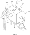
- FIG. 6 is a perspective view of a plasma furnace according to a second embodiment of the present invention
- FIG. 7 is a plan view of a plasma furnace according to a second embodiment of the present invention.
- a duplicate description of the same configuration as the first embodiment will be omitted.
- the furnace body 200 has a cylindroid shape as a whole, and the upper portion of the melting chamber is formed by the upper surface 211, 212 comprising a horizontal upper surface 211, and an inclined upper surface 212 having a predefined angle to the rear and lower direction.
- the inclined upper surface 212 is provided at one side of the furnace body 200 and is positioned to be opposite in direction to the input apparatus 220, and more preferably, the input apparatus 220 and the inclined upper surface 212 are positioned along (X-axis) the direction of major axis of the elliptical furnace body 200.
- the furnace body 200 includes a vertical lateral surface 200a that contacts the inclined upper surface 212 vertically.
- two mix-type plasma torches 291, 292 which can operate independently of each other, are installed symmetrically on the inclined upper surface 112.
- FIG. 8 is a perspective view of a plasma furnace according to a third embodiment of the present invention
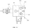
- FIG. 9 is a plan view of a plasma furnace according to a third embodiment of the present invention. As described above, a duplicated description of the same configuration as the first embodiment will be omitted.
- the furnace body 300 has a polyhedral structure composed of a plurality of rectangles, which is an overall hexahedron structure except the upper surface.
- the upper surface 311, 312 forming the upper portion of the melting chamber comprises a horizontal upper surface 311 and an inclined upper surface 312 having a slope to the rear and lower direction with respect to the horizontal upper surface 311.
- the inclined upper surface 312 is provided at one side of the furnace body 300 so as to be positioned opposite to the input apparatus 320 where the drum type waste is input.
Landscapes
- Engineering & Computer Science (AREA)
- General Engineering & Computer Science (AREA)
- Mechanical Engineering (AREA)
- Physics & Mathematics (AREA)
- High Energy & Nuclear Physics (AREA)
- Environmental & Geological Engineering (AREA)
- Plasma & Fusion (AREA)
- Gasification And Melting Of Waste (AREA)
- Processing Of Solid Wastes (AREA)
Applications Claiming Priority (2)
| Application Number | Priority Date | Filing Date | Title |
|---|---|---|---|
| KR1020150114044A KR101664866B1 (ko) | 2015-08-12 | 2015-08-12 | 플라즈마 용융로 |
| PCT/KR2015/009775 WO2017026576A1 (fr) | 2015-08-12 | 2015-09-17 | Four de fusion à plasma |
Publications (3)
| Publication Number | Publication Date |
|---|---|
| EP3336855A1 true EP3336855A1 (fr) | 2018-06-20 |
| EP3336855A4 EP3336855A4 (fr) | 2018-12-26 |
| EP3336855B1 EP3336855B1 (fr) | 2020-11-04 |
Family
ID=57174013
Family Applications (1)
| Application Number | Title | Priority Date | Filing Date |
|---|---|---|---|
| EP15901058.6A Active EP3336855B1 (fr) | 2015-08-12 | 2015-09-17 | Four de fusion à plasma |
Country Status (6)
| Country | Link |
|---|---|
| US (1) | US10861613B2 (fr) |
| EP (1) | EP3336855B1 (fr) |
| JP (1) | JP2018525597A (fr) |
| KR (1) | KR101664866B1 (fr) |
| CN (1) | CN107924729A (fr) |
| WO (1) | WO2017026576A1 (fr) |
Families Citing this family (3)
| Publication number | Priority date | Publication date | Assignee | Title |
|---|---|---|---|---|
| JP6800780B2 (ja) * | 2017-03-07 | 2020-12-16 | 日鉄エンジニアリング株式会社 | プラズマトーチ、溶湯加熱装置及び溶湯加熱方法 |
| CN114743711A (zh) * | 2022-04-21 | 2022-07-12 | 江苏天楹等离子体科技有限公司 | 一种低放射性熔融玻璃体自动接渣装置及其工艺 |
| KR102870977B1 (ko) | 2023-03-02 | 2025-10-14 | 한국수력원자력 주식회사 | 폐기물 드럼의 전처리 장치를 포함하는 플라즈마 토치 용융로 시스템 및 그 처리방법 |
Family Cites Families (25)
| Publication number | Priority date | Publication date | Assignee | Title |
|---|---|---|---|---|
| US3744438A (en) * | 1968-12-24 | 1973-07-10 | Pyro Magnetics Corp | Incinerating |
| DE68927849T2 (de) * | 1988-11-17 | 1997-07-24 | Schuller Corp | Verfahren zum Schmelzen von Stoffen |
| AT393901B (de) * | 1990-02-09 | 1992-01-10 | Voest Alpine Ind Anlagen | Anlage zur behandlung und erschmelzung von metallen, metallverbindungen und/oder metallegierungen oder zur herstellung von calciumcarbid |
| US5280757A (en) * | 1992-04-13 | 1994-01-25 | Carter George W | Municipal solid waste disposal process |
| US5548611A (en) * | 1993-05-19 | 1996-08-20 | Schuller International, Inc. | Method for the melting, combustion or incineration of materials and apparatus therefor |
| GB2298701B (en) * | 1993-11-19 | 1998-07-01 | Phoenix Environmental Limited | System for converting solid waste material into environmentally safe products |
| US5410121A (en) * | 1994-03-09 | 1995-04-25 | Retech, Inc. | System for feeding toxic waste drums into a treatment chamber |
| FR2764877B1 (fr) * | 1997-06-20 | 1999-09-03 | Europlasma | Procede de vitrification d'un materiau pulverulent et dispositif pour la mise en oeuvre de ce procede |
| US6155182A (en) * | 1997-09-04 | 2000-12-05 | Tsangaris; Andreas | Plant for gasification of waste |
| US6313429B1 (en) * | 1998-08-27 | 2001-11-06 | Retech Services, Inc. | Dual mode plasma arc torch for use with plasma arc treatment system and method of use thereof |
| KR200343807Y1 (ko) | 1998-12-30 | 2004-05-17 | 삼성중공업 주식회사 | 플라즈마 용융로 |
| KR100334439B1 (ko) * | 1998-12-30 | 2002-08-28 | 삼성중공업 주식회사 | 플라즈마용융로슬래그배출장치 |
| JP2001254927A (ja) * | 2000-03-10 | 2001-09-21 | Nissei Ltd | 溶融炉 |
| KR20010008137A (ko) * | 2000-11-10 | 2001-02-05 | 이해곤 | 신발끈의 결속장치 |
| JP2002228137A (ja) * | 2001-01-31 | 2002-08-14 | Mitsubishi Heavy Ind Ltd | プラズマ灰廃棄物溶融炉 |
| JP2003317930A (ja) * | 2002-04-23 | 2003-11-07 | Ebara Corp | プラズマ式溶融炉装置 |
| CA2457335A1 (fr) * | 2003-02-12 | 2004-08-12 | Rcl Plasma, Inc. | Systeme de traitement de dechets dangereux muni de plusieurs generateurs de plasma |
| KR100582753B1 (ko) * | 2004-04-29 | 2006-05-23 | 주식회사 애드플라텍 | 선회식 플라즈마 열분해/용융로 |
| US7644668B2 (en) * | 2005-10-28 | 2010-01-12 | Atomic Energy Council | Feeding system for plasma melting-furnace |
| KR101032055B1 (ko) | 2008-11-26 | 2011-05-02 | 지에스플라텍 주식회사 | 플라즈마 토치 용융로의 용융물 출탕 장치 및 방법 |
| JP2012132631A (ja) * | 2010-12-22 | 2012-07-12 | Tokai Konetsu Kogyo Co Ltd | 溶融炉 |
| KR20120128752A (ko) * | 2011-05-18 | 2012-11-28 | 주식회사 플라즈마 그린 테크놀러지 | 플라즈마를 이용한 방사성 폐기물 처리장치 및 처리방법 |
| KR101301055B1 (ko) | 2013-04-11 | 2013-08-28 | 지에스플라텍 주식회사 | 폐기물 플라즈마 용융로, 폐기물 플라즈마 용융 시스템, 및 폐기물 플라즈마 용융 방법 |
| KR101457368B1 (ko) * | 2013-10-04 | 2014-11-03 | 한국수력원자력 주식회사 | 용융물의 유도가열식 배출장치 및 방법 |
| KR101418105B1 (ko) * | 2014-04-24 | 2014-07-11 | 주식회사 플라즈마 그린 테크놀로지 | 무기성 폐자원을 이용한 암면 부산물 제조를 위한 플라즈마 토치형 용융장치 및 그 제조방법 |
-
2015
- 2015-08-12 KR KR1020150114044A patent/KR101664866B1/ko active Active
- 2015-09-17 US US15/750,272 patent/US10861613B2/en active Active
- 2015-09-17 CN CN201580082386.8A patent/CN107924729A/zh active Pending
- 2015-09-17 JP JP2018504286A patent/JP2018525597A/ja active Pending
- 2015-09-17 EP EP15901058.6A patent/EP3336855B1/fr active Active
- 2015-09-17 WO PCT/KR2015/009775 patent/WO2017026576A1/fr not_active Ceased
Also Published As
| Publication number | Publication date |
|---|---|
| US10861613B2 (en) | 2020-12-08 |
| WO2017026576A1 (fr) | 2017-02-16 |
| EP3336855B1 (fr) | 2020-11-04 |
| KR101664866B1 (ko) | 2016-10-13 |
| US20180261347A1 (en) | 2018-09-13 |
| JP2018525597A (ja) | 2018-09-06 |
| EP3336855A4 (fr) | 2018-12-26 |
| CN107924729A (zh) | 2018-04-17 |
Similar Documents
| Publication | Publication Date | Title |
|---|---|---|
| JP6487438B2 (ja) | 有機および金属廃棄物を焼却、溶融、およびガラス化するための方法および装置 | |
| US10871288B2 (en) | Sealed plasma melting furnace for treating low- and intermediate-level radioactive waste | |
| KR101379443B1 (ko) | 방사성 폐기물 처리를 위한 플라즈마 복합처리장치 | |
| EP3336855B1 (fr) | Four de fusion à plasma | |
| EP3336854B1 (fr) | Four de fusion à plasma à grilles de décharge latérales | |
| KR101661112B1 (ko) | 플라즈마 용융로 설비의 드럼형 폐기물 투입장치 | |
| KR101759242B1 (ko) | 폐전선 및 통신선 열분해장치 | |
| KR101278210B1 (ko) | 이동형 방사성 금속폐기물 용융제염장치 | |
| KR102003277B1 (ko) | 중저준위 방사성 폐기물 처리용 플라즈마 용융장치 | |
| KR101606174B1 (ko) | 복합용융로 장치 | |
| KR101569758B1 (ko) | 금속섹터를 갖는 복합용융로 장치 | |
| KR101680821B1 (ko) | 슬릿을 갖는 용융로 용탕배출장치 | |
| KR100993290B1 (ko) | 유가 원소 회수 장치 | |
| KR101615699B1 (ko) | 복합용융로 장치 | |
| KR101728302B1 (ko) | 냉각구조를 갖는 용탕배출장치 및 용탕배출 방법 | |
| CN108463680B (zh) | 金属熔化装置 | |
| KR20180137681A (ko) | 질소냉각구조를 갖는 용탕배출장치 | |
| TWI480890B (zh) | 低放射性廢棄物電弧熔融爐與兩段式洩漿裝置 | |
| KR101912722B1 (ko) | 유도가열 방식이 구비된 폐기물 처리장치 | |
| KR102027071B1 (ko) | 방사성폐기물의 용융 및 소각장치 | |
| KR100456776B1 (ko) | 방사성 건조폐기물의 전처리장치와 이 처리장치가 채택된방사성폐기물 소각ㆍ유리고화 처리시스템 | |
| KR20220111841A (ko) | 유리화설비의 폐기물 공급장치 | |
| KR20230101380A (ko) | 플라즈마 절단 및 용융토치로 구성된 폐기물 드럼 투입식 경사로 구조 용융로 시스템 | |
| KR101718006B1 (ko) | 폐열회수장치 | |
| JP2001254927A (ja) | 溶融炉 |
Legal Events
| Date | Code | Title | Description |
|---|---|---|---|
| STAA | Information on the status of an ep patent application or granted ep patent |
Free format text: STATUS: THE INTERNATIONAL PUBLICATION HAS BEEN MADE |
|
| PUAI | Public reference made under article 153(3) epc to a published international application that has entered the european phase |
Free format text: ORIGINAL CODE: 0009012 |
|
| STAA | Information on the status of an ep patent application or granted ep patent |
Free format text: STATUS: REQUEST FOR EXAMINATION WAS MADE |
|
| 17P | Request for examination filed |
Effective date: 20180312 |
|
| AK | Designated contracting states |
Kind code of ref document: A1 Designated state(s): AL AT BE BG CH CY CZ DE DK EE ES FI FR GB GR HR HU IE IS IT LI LT LU LV MC MK MT NL NO PL PT RO RS SE SI SK SM TR |
|
| AX | Request for extension of the european patent |
Extension state: BA ME |
|
| DAV | Request for validation of the european patent (deleted) | ||
| DAX | Request for extension of the european patent (deleted) | ||
| A4 | Supplementary search report drawn up and despatched |
Effective date: 20181123 |
|
| RIC1 | Information provided on ipc code assigned before grant |
Ipc: F27B 3/04 20060101ALI20181116BHEP Ipc: F27D 3/00 20060101ALI20181116BHEP Ipc: G21F 9/30 20060101AFI20181116BHEP Ipc: F27D 3/14 20060101ALI20181116BHEP Ipc: F23G 5/08 20060101ALI20181116BHEP Ipc: F27D 11/08 20060101ALI20181116BHEP Ipc: F23G 5/44 20060101ALI20181116BHEP Ipc: F27D 99/00 20100101ALI20181116BHEP Ipc: F27B 17/00 20060101ALI20181116BHEP |
|
| STAA | Information on the status of an ep patent application or granted ep patent |
Free format text: STATUS: EXAMINATION IS IN PROGRESS |
|
| 17Q | First examination report despatched |
Effective date: 20191024 |
|
| GRAP | Despatch of communication of intention to grant a patent |
Free format text: ORIGINAL CODE: EPIDOSNIGR1 |
|
| STAA | Information on the status of an ep patent application or granted ep patent |
Free format text: STATUS: GRANT OF PATENT IS INTENDED |
|
| INTG | Intention to grant announced |
Effective date: 20200602 |
|
| RAP1 | Party data changed (applicant data changed or rights of an application transferred) |
Owner name: KOREA HYDRO & NUCLEAR POWER CO., LTD |
|
| GRAS | Grant fee paid |
Free format text: ORIGINAL CODE: EPIDOSNIGR3 |
|
| GRAA | (expected) grant |
Free format text: ORIGINAL CODE: 0009210 |
|
| STAA | Information on the status of an ep patent application or granted ep patent |
Free format text: STATUS: THE PATENT HAS BEEN GRANTED |
|
| AK | Designated contracting states |
Kind code of ref document: B1 Designated state(s): AL AT BE BG CH CY CZ DE DK EE ES FI FR GB GR HR HU IE IS IT LI LT LU LV MC MK MT NL NO PL PT RO RS SE SI SK SM TR |
|
| REG | Reference to a national code |
Ref country code: GB Ref legal event code: FG4D |
|
| REG | Reference to a national code |
Ref country code: CH Ref legal event code: EP |
|
| REG | Reference to a national code |
Ref country code: AT Ref legal event code: REF Ref document number: 1331866 Country of ref document: AT Kind code of ref document: T Effective date: 20201115 |
|
| REG | Reference to a national code |
Ref country code: IE Ref legal event code: FG4D |
|
| REG | Reference to a national code |
Ref country code: DE Ref legal event code: R096 Ref document number: 602015061714 Country of ref document: DE |
|
| REG | Reference to a national code |
Ref country code: NL Ref legal event code: MP Effective date: 20201104 |
|
| REG | Reference to a national code |
Ref country code: AT Ref legal event code: MK05 Ref document number: 1331866 Country of ref document: AT Kind code of ref document: T Effective date: 20201104 |
|
| PG25 | Lapsed in a contracting state [announced via postgrant information from national office to epo] |
Ref country code: GR Free format text: LAPSE BECAUSE OF FAILURE TO SUBMIT A TRANSLATION OF THE DESCRIPTION OR TO PAY THE FEE WITHIN THE PRESCRIBED TIME-LIMIT Effective date: 20210205 Ref country code: RS Free format text: LAPSE BECAUSE OF FAILURE TO SUBMIT A TRANSLATION OF THE DESCRIPTION OR TO PAY THE FEE WITHIN THE PRESCRIBED TIME-LIMIT Effective date: 20201104 Ref country code: PT Free format text: LAPSE BECAUSE OF FAILURE TO SUBMIT A TRANSLATION OF THE DESCRIPTION OR TO PAY THE FEE WITHIN THE PRESCRIBED TIME-LIMIT Effective date: 20210304 Ref country code: FI Free format text: LAPSE BECAUSE OF FAILURE TO SUBMIT A TRANSLATION OF THE DESCRIPTION OR TO PAY THE FEE WITHIN THE PRESCRIBED TIME-LIMIT Effective date: 20201104 Ref country code: NO Free format text: LAPSE BECAUSE OF FAILURE TO SUBMIT A TRANSLATION OF THE DESCRIPTION OR TO PAY THE FEE WITHIN THE PRESCRIBED TIME-LIMIT Effective date: 20210204 |
|
| PG25 | Lapsed in a contracting state [announced via postgrant information from national office to epo] |
Ref country code: ES Free format text: LAPSE BECAUSE OF FAILURE TO SUBMIT A TRANSLATION OF THE DESCRIPTION OR TO PAY THE FEE WITHIN THE PRESCRIBED TIME-LIMIT Effective date: 20201104 Ref country code: AT Free format text: LAPSE BECAUSE OF FAILURE TO SUBMIT A TRANSLATION OF THE DESCRIPTION OR TO PAY THE FEE WITHIN THE PRESCRIBED TIME-LIMIT Effective date: 20201104 Ref country code: IS Free format text: LAPSE BECAUSE OF FAILURE TO SUBMIT A TRANSLATION OF THE DESCRIPTION OR TO PAY THE FEE WITHIN THE PRESCRIBED TIME-LIMIT Effective date: 20210304 Ref country code: LV Free format text: LAPSE BECAUSE OF FAILURE TO SUBMIT A TRANSLATION OF THE DESCRIPTION OR TO PAY THE FEE WITHIN THE PRESCRIBED TIME-LIMIT Effective date: 20201104 Ref country code: PL Free format text: LAPSE BECAUSE OF FAILURE TO SUBMIT A TRANSLATION OF THE DESCRIPTION OR TO PAY THE FEE WITHIN THE PRESCRIBED TIME-LIMIT Effective date: 20201104 Ref country code: SE Free format text: LAPSE BECAUSE OF FAILURE TO SUBMIT A TRANSLATION OF THE DESCRIPTION OR TO PAY THE FEE WITHIN THE PRESCRIBED TIME-LIMIT Effective date: 20201104 Ref country code: BG Free format text: LAPSE BECAUSE OF FAILURE TO SUBMIT A TRANSLATION OF THE DESCRIPTION OR TO PAY THE FEE WITHIN THE PRESCRIBED TIME-LIMIT Effective date: 20210204 |
|
| REG | Reference to a national code |
Ref country code: LT Ref legal event code: MG9D |
|
| PG25 | Lapsed in a contracting state [announced via postgrant information from national office to epo] |
Ref country code: HR Free format text: LAPSE BECAUSE OF FAILURE TO SUBMIT A TRANSLATION OF THE DESCRIPTION OR TO PAY THE FEE WITHIN THE PRESCRIBED TIME-LIMIT Effective date: 20201104 |
|
| PG25 | Lapsed in a contracting state [announced via postgrant information from national office to epo] |
Ref country code: RO Free format text: LAPSE BECAUSE OF FAILURE TO SUBMIT A TRANSLATION OF THE DESCRIPTION OR TO PAY THE FEE WITHIN THE PRESCRIBED TIME-LIMIT Effective date: 20201104 Ref country code: SK Free format text: LAPSE BECAUSE OF FAILURE TO SUBMIT A TRANSLATION OF THE DESCRIPTION OR TO PAY THE FEE WITHIN THE PRESCRIBED TIME-LIMIT Effective date: 20201104 Ref country code: SM Free format text: LAPSE BECAUSE OF FAILURE TO SUBMIT A TRANSLATION OF THE DESCRIPTION OR TO PAY THE FEE WITHIN THE PRESCRIBED TIME-LIMIT Effective date: 20201104 Ref country code: LT Free format text: LAPSE BECAUSE OF FAILURE TO SUBMIT A TRANSLATION OF THE DESCRIPTION OR TO PAY THE FEE WITHIN THE PRESCRIBED TIME-LIMIT Effective date: 20201104 Ref country code: EE Free format text: LAPSE BECAUSE OF FAILURE TO SUBMIT A TRANSLATION OF THE DESCRIPTION OR TO PAY THE FEE WITHIN THE PRESCRIBED TIME-LIMIT Effective date: 20201104 Ref country code: CZ Free format text: LAPSE BECAUSE OF FAILURE TO SUBMIT A TRANSLATION OF THE DESCRIPTION OR TO PAY THE FEE WITHIN THE PRESCRIBED TIME-LIMIT Effective date: 20201104 |
|
| REG | Reference to a national code |
Ref country code: DE Ref legal event code: R097 Ref document number: 602015061714 Country of ref document: DE |
|
| PG25 | Lapsed in a contracting state [announced via postgrant information from national office to epo] |
Ref country code: DK Free format text: LAPSE BECAUSE OF FAILURE TO SUBMIT A TRANSLATION OF THE DESCRIPTION OR TO PAY THE FEE WITHIN THE PRESCRIBED TIME-LIMIT Effective date: 20201104 |
|
| PLBE | No opposition filed within time limit |
Free format text: ORIGINAL CODE: 0009261 |
|
| STAA | Information on the status of an ep patent application or granted ep patent |
Free format text: STATUS: NO OPPOSITION FILED WITHIN TIME LIMIT |
|
| 26N | No opposition filed |
Effective date: 20210805 |
|
| PG25 | Lapsed in a contracting state [announced via postgrant information from national office to epo] |
Ref country code: NL Free format text: LAPSE BECAUSE OF FAILURE TO SUBMIT A TRANSLATION OF THE DESCRIPTION OR TO PAY THE FEE WITHIN THE PRESCRIBED TIME-LIMIT Effective date: 20201104 Ref country code: IT Free format text: LAPSE BECAUSE OF FAILURE TO SUBMIT A TRANSLATION OF THE DESCRIPTION OR TO PAY THE FEE WITHIN THE PRESCRIBED TIME-LIMIT Effective date: 20201104 Ref country code: AL Free format text: LAPSE BECAUSE OF FAILURE TO SUBMIT A TRANSLATION OF THE DESCRIPTION OR TO PAY THE FEE WITHIN THE PRESCRIBED TIME-LIMIT Effective date: 20201104 |
|
| PG25 | Lapsed in a contracting state [announced via postgrant information from national office to epo] |
Ref country code: SI Free format text: LAPSE BECAUSE OF FAILURE TO SUBMIT A TRANSLATION OF THE DESCRIPTION OR TO PAY THE FEE WITHIN THE PRESCRIBED TIME-LIMIT Effective date: 20201104 |
|
| REG | Reference to a national code |
Ref country code: DE Ref legal event code: R119 Ref document number: 602015061714 Country of ref document: DE |
|
| REG | Reference to a national code |
Ref country code: BE Ref legal event code: MM Effective date: 20210930 |
|
| PG25 | Lapsed in a contracting state [announced via postgrant information from national office to epo] |
Ref country code: IS Free format text: LAPSE BECAUSE OF FAILURE TO SUBMIT A TRANSLATION OF THE DESCRIPTION OR TO PAY THE FEE WITHIN THE PRESCRIBED TIME-LIMIT Effective date: 20210304 Ref country code: MC Free format text: LAPSE BECAUSE OF FAILURE TO SUBMIT A TRANSLATION OF THE DESCRIPTION OR TO PAY THE FEE WITHIN THE PRESCRIBED TIME-LIMIT Effective date: 20201104 |
|
| PG25 | Lapsed in a contracting state [announced via postgrant information from national office to epo] |
Ref country code: LU Free format text: LAPSE BECAUSE OF NON-PAYMENT OF DUE FEES Effective date: 20210917 Ref country code: IE Free format text: LAPSE BECAUSE OF NON-PAYMENT OF DUE FEES Effective date: 20210917 Ref country code: FR Free format text: LAPSE BECAUSE OF NON-PAYMENT OF DUE FEES Effective date: 20210930 Ref country code: DE Free format text: LAPSE BECAUSE OF NON-PAYMENT OF DUE FEES Effective date: 20220401 Ref country code: BE Free format text: LAPSE BECAUSE OF NON-PAYMENT OF DUE FEES Effective date: 20210930 |
|
| PG25 | Lapsed in a contracting state [announced via postgrant information from national office to epo] |
Ref country code: HU Free format text: LAPSE BECAUSE OF FAILURE TO SUBMIT A TRANSLATION OF THE DESCRIPTION OR TO PAY THE FEE WITHIN THE PRESCRIBED TIME-LIMIT; INVALID AB INITIO Effective date: 20150917 |
|
| PG25 | Lapsed in a contracting state [announced via postgrant information from national office to epo] |
Ref country code: CY Free format text: LAPSE BECAUSE OF FAILURE TO SUBMIT A TRANSLATION OF THE DESCRIPTION OR TO PAY THE FEE WITHIN THE PRESCRIBED TIME-LIMIT Effective date: 20201104 |
|
| PG25 | Lapsed in a contracting state [announced via postgrant information from national office to epo] |
Ref country code: MK Free format text: LAPSE BECAUSE OF FAILURE TO SUBMIT A TRANSLATION OF THE DESCRIPTION OR TO PAY THE FEE WITHIN THE PRESCRIBED TIME-LIMIT Effective date: 20201104 |
|
| PG25 | Lapsed in a contracting state [announced via postgrant information from national office to epo] |
Ref country code: MT Free format text: LAPSE BECAUSE OF FAILURE TO SUBMIT A TRANSLATION OF THE DESCRIPTION OR TO PAY THE FEE WITHIN THE PRESCRIBED TIME-LIMIT Effective date: 20201104 |
|
| REG | Reference to a national code |
Ref country code: CH Ref legal event code: U11 Free format text: ST27 STATUS EVENT CODE: U-0-0-U10-U11 (AS PROVIDED BY THE NATIONAL OFFICE) Effective date: 20251006 |
|
| PG25 | Lapsed in a contracting state [announced via postgrant information from national office to epo] |
Ref country code: TR Free format text: LAPSE BECAUSE OF FAILURE TO SUBMIT A TRANSLATION OF THE DESCRIPTION OR TO PAY THE FEE WITHIN THE PRESCRIBED TIME-LIMIT Effective date: 20201104 |
|
| PGFP | Annual fee paid to national office [announced via postgrant information from national office to epo] |
Ref country code: GB Payment date: 20251001 Year of fee payment: 11 |
|
| PGFP | Annual fee paid to national office [announced via postgrant information from national office to epo] |
Ref country code: CH Payment date: 20251006 Year of fee payment: 11 |