EP3337294B2 - Appareil de cuisson à induction et son procédé de commande - Google Patents
Appareil de cuisson à induction et son procédé de commande Download PDFInfo
- Publication number
- EP3337294B2 EP3337294B2 EP17207098.9A EP17207098A EP3337294B2 EP 3337294 B2 EP3337294 B2 EP 3337294B2 EP 17207098 A EP17207098 A EP 17207098A EP 3337294 B2 EP3337294 B2 EP 3337294B2
- Authority
- EP
- European Patent Office
- Prior art keywords
- switch
- cooking apparatus
- induction heat
- battery
- heat cooking
- Prior art date
- Legal status (The legal status is an assumption and is not a legal conclusion. Google has not performed a legal analysis and makes no representation as to the accuracy of the status listed.)
- Active
Links
Images


Classifications
-
- H—ELECTRICITY
- H05—ELECTRIC TECHNIQUES NOT OTHERWISE PROVIDED FOR
- H05B—ELECTRIC HEATING; ELECTRIC LIGHT SOURCES NOT OTHERWISE PROVIDED FOR; CIRCUIT ARRANGEMENTS FOR ELECTRIC LIGHT SOURCES, IN GENERAL
- H05B6/00—Heating by electric, magnetic or electromagnetic fields
- H05B6/02—Induction heating
- H05B6/10—Induction heating apparatus, other than furnaces, for specific applications
- H05B6/12—Cooking devices
-
- H—ELECTRICITY
- H05—ELECTRIC TECHNIQUES NOT OTHERWISE PROVIDED FOR
- H05B—ELECTRIC HEATING; ELECTRIC LIGHT SOURCES NOT OTHERWISE PROVIDED FOR; CIRCUIT ARRANGEMENTS FOR ELECTRIC LIGHT SOURCES, IN GENERAL
- H05B6/00—Heating by electric, magnetic or electromagnetic fields
- H05B6/02—Induction heating
- H05B6/04—Sources of current
-
- H—ELECTRICITY
- H05—ELECTRIC TECHNIQUES NOT OTHERWISE PROVIDED FOR
- H05B—ELECTRIC HEATING; ELECTRIC LIGHT SOURCES NOT OTHERWISE PROVIDED FOR; CIRCUIT ARRANGEMENTS FOR ELECTRIC LIGHT SOURCES, IN GENERAL
- H05B6/00—Heating by electric, magnetic or electromagnetic fields
- H05B6/02—Induction heating
- H05B6/06—Control, e.g. of temperature, of power
- H05B6/062—Control, e.g. of temperature, of power for cooking plates or the like
-
- H—ELECTRICITY
- H05—ELECTRIC TECHNIQUES NOT OTHERWISE PROVIDED FOR
- H05B—ELECTRIC HEATING; ELECTRIC LIGHT SOURCES NOT OTHERWISE PROVIDED FOR; CIRCUIT ARRANGEMENTS FOR ELECTRIC LIGHT SOURCES, IN GENERAL
- H05B6/00—Heating by electric, magnetic or electromagnetic fields
- H05B6/02—Induction heating
- H05B6/06—Control, e.g. of temperature, of power
-
- H—ELECTRICITY
- H05—ELECTRIC TECHNIQUES NOT OTHERWISE PROVIDED FOR
- H05B—ELECTRIC HEATING; ELECTRIC LIGHT SOURCES NOT OTHERWISE PROVIDED FOR; CIRCUIT ARRANGEMENTS FOR ELECTRIC LIGHT SOURCES, IN GENERAL
- H05B6/00—Heating by electric, magnetic or electromagnetic fields
- H05B6/02—Induction heating
- H05B6/10—Induction heating apparatus, other than furnaces, for specific applications
- H05B6/12—Cooking devices
- H05B6/1209—Cooking devices induction cooking plates or the like and devices to be used in combination with them
- H05B6/1236—Cooking devices induction cooking plates or the like and devices to be used in combination with them adapted to induce current in a coil to supply power to a device and electrical heating devices powered in this way
Definitions
- the present disclosure relates to an induction heat cooking apparatus and a method for operating the same.
- Electric ranges include highlight-type electric ranges for converting electricity into heat by using a nichrome wire having high electrical resistance and induction-type electric ranges for generating magnetic fields to apply heat through an induction heating method.
- Induction heat cooking apparatuses may mean electric ranges that operate according to an induction method. A specific operation principle of induction heat cooking apparatuses will be described as follows.
- high frequency current flows through a working coil or a heating coil, which is provided in the induction heat cooking apparatus.
- lines of strong magnetic force are generated.
- the lines of the magnetic force generated in the working coil or the heating coil generate eddy current when passing through a cooking device.
- heat is generated to heat a container itself. Then, since the container is heated, contents within the container are heated.
- the induction heat cooking apparatus is an electric cooking apparatus using a principle of inducing heat to the cooking device itself to heat the contents.
- pollution of indoor air may be reduced because oxygen is not consumed, and exhaust gases are not exhausted.
- the induction heat cooking apparatus has high energy efficiency and stability, and also, the container itself is heated to reduce a risk of burns.
- Document US 3697717 discloses an induction heat cooking apparatus of the prior art.
- an induction heat cooking apparatus includes a switch for connecting one of an external power source and a battery and an inverter using a voltage supplied from a power supply source connected by the switch.
- the induction heat cooking apparatus may use a low voltage supplied through the battery when power less than a reference level is outputted.
- the induction heat cooking apparatus may include a diode for preventing an external power source from being short-circuited with the battery.
- Embodiments provide an induction heat cooking apparatus that is capable of operating in a wired mode and a wireless mode.
- Embodiments also provide an induction heat cooking apparatus that is capable of constantly outputting low power.
- Embodiments also secure safety in an induction heat cooking apparatus that is capable of operating in wired/wireless manners and an induction heat cooking apparatus that is capable of linearly outputting low power.
- Fig. 1 is a view for explaining an operation of an induction heat cooking apparatus.
- a cooking device 1 may be disposed on an induction heat cooking apparatus 10.
- the induction heat cooking apparatus 10 may heat the cooking device 1 disposed thereon.
- the induction heat cooking apparatus 10 may generate magnetic fields 20. A portion of the magnetic fields 20 generated in the induction heat cooking apparatus 10 may pass through the cooking device 1.
- the magnetic fields 20 may generate eddy current 30 in the cooking device 1.
- the eddy current 30 heats the cooking device 1 itself, and the heat is conducted to be transferred up to the inside of the cooking device 1.
- the induction heat cooking apparatus 10 operates in a manner in which the contents of the cooking device 1 are cooked.
- the cooking device 1 When the electric resistance component is not contained in the material for forming the cooking device 1, the eddy current 30 is not generated. Thus, in this case, the cooking device 1 is not heated.
- the cooking device 1 may be a stainless steel container or a metal container such as enamel or cast iron container.
- a method for generating the magnetic fields 20 by using the induction heat cooking apparatus 10 will be described with reference to Fig. 2 .
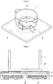
- Fig. 2 is a side cross-sectional view of the induction heat cooking apparatus.
- the induction heat cooking apparatus 10 may include at least one of an upper plate glass 11, a heating coil 12, and a ferrite 13.
- the upper plate glass 11 may protect the inside of the induction heat cooking apparatus 10 and support the cooking device 1.
- the upper plate glass 11 may be provided as a tempered glass made of a ceramic material that is synthesized with various minerals. Thus, the inside of the induction heat cooking apparatus 10 may be protected from the outside. Also, the upper plate glass 11 may support the cooking device 1 disposed thereon. Thus, the cooking device 1 may be disposed on an upper portion of the upper plate glass 11.
- the heating coil 12 generates the magnetic fields 20 for heating the cooking device 1.
- the heating coil 12 may be disposed below the upper plate glass 11.
- Current may flow or may not flow through the heating coil 12 according to power turn on/off of the induction heat cooking apparatus 10. Also, even when the current flows through the heating coil 12, an amount of current flowing through the heating coil 12 may vary according to firepower levels of the induction heat cooking apparatus 10.
- the heating coil 12 may generate the magnetic fields 20.
- the magnetic fields 20 generated in the heating coil 12 may pass through the cooking device 1.
- the magnetic fields 20 passing through the cooking device 1 may encounter the electrical resistance component contained in the cooking device 1 to generated eddy current (not shown).
- the eddy current may heat the cooking device 1 to cook the contents of the cooking device 1.
- a flow direction of the magnetic fields 20 generated in the heating coil 12 may be determined by a direction of the current flowing through the heating coil 12.
- the flow direction of the magnetic fields 20 may be converted by a frequency of the AC current. For example, when AC current of about 60 Hz flows through the heating coil 12, the flow direction of the magnetic fields 20 is converted about 60 times per second.
- the ferrite 13 is a component for protecting an internal circuit of the induction heat cooking apparatus 10.
- the ferrite 13 serves as a shield for blocking an influence of the magnetic fields 20 generated in the heating coil 12 or electromagnetic fields generated from the outside on the internal circuit of the induction heat cooking apparatus 10.
- the ferrite 13 may be made of a material having high permeability.
- the ferrite 13 may induce the magnetic fields introduced into the induction heat cooking apparatus 10 to flow through the ferrite 13 without being radiated.
- a state in which the magnetic fields 20 generated in the heating coil 12 moves by the ferrite 13 is illustrated in Fig. 2 .
- Fig. 3 is a circuit diagram illustrating an example of an induction heat cooking apparatus according to a related art. Particularly, Fig. 3 is a circuit diagram of the induction heat cooking apparatus when one inverter and one heating coil are provided.
- the induction heat cooking apparatus includes at least one of a rectifier 120, a DC link capacitor 130, an inverter 140, a heating coil 150, a resonance capacitor 160, and a switching mode power supply (SMPS) 170.
- a rectifier 120 a DC link capacitor 130
- an inverter 140 a heating coil 150
- a resonance capacitor 160 a switching mode power supply 170.
- SMPS switching mode power supply
- An external power source 110 may be an alternation current (AC) input power source.
- the external power source 110 may supply AC power to the induction heat cooking apparatus.
- the external power source 110 may supply the AC power to the rectifier 120 of the induction heat cooking apparatus.
- the rectifier 120 is an electrical device for converting AC power into DC power.
- the rectifier 120 converts an AC voltage supplied through the external power source 110 into a DC voltage.
- Both DC terminals of the rectifier 120, through which the DC voltage is outputted, may be called DC links.
- a voltage measured at each of both the DC terminals 121 is referred to as a DC link voltage.
- output power may vary according to the DC link voltage.
- the DC link capacitor 130 serve as a buffer between the external power source 110 and the inverter 140. Particularly, the DC link capacitor 130 may be used to maintain the DC link voltage converted through the rectifier 120 and supply the DC link voltage up to the inverter 140.
- the inverter 140 serves as a switch for switching the voltage applied to the heating coil 150 so that high-frequency current flows through the heating coil 150.
- the inverter 140 drives a switching device, which is generally provided as an insulated gate bipolar transistor (IGBT), to allow the high-frequency current to flow through the heating coil 150, thereby generating high-frequency magnetic fields in the heating coil 150.
- IGBT insulated gate bipolar transistor
- the current may flow or may not flow through the heating coil 150 according to whether the switching device is driven.
- the heating coil 150 may generate the magnetic fields due to the flowing of the current to heat the cooking device.
- the heating coil 150 has one side connected to a connection point of the switching device of the inverter 140 and the other side connected to the resonance capacitor 160.
- the driving of the switching device may be performed by a driving unit (not shown).
- a high-frequency voltage may be applied to the heating coil 150 while the switching devices alternately operate under the control of a switching time outputted from the driving unit. Also, since the turn on/off time of the switching device, which is applied from the driving unit, is controlled to be gradually compensated, the voltage supplied to the heating coil 150 may be converted from a low voltage into a high voltage.
- the resonance capacitor 160 is a component that serves as a buffer.
- the resonance capacitor 160 may adjust a saturation voltage rising ratio during the turn-off of the switching device to affect energy loss during the turn-off time.
- the SMPS 170 means a power supply device for efficiently converting the power according to the switching operation.
- the SMPS 170 converts the DC input voltage into a square-wave voltage and then obtains the DC output voltage controlled through a filter.
- the SMPS 170 may control the flow of the power by using a switching process to minimize unnecessary loss.
- a resonance frequency of the induction heat cooking apparatus which has the circuit diagram as illustrated in Fig. 3 , is determined by an inductance value of the heating coil 150 and a capacitance value of the resonance capacitor 160.
- a resonance curve may be formed based on the determined resonance frequency.
- the resonance curve may represent power outputted according to a frequency band.
- Fig. 4 is a view illustrating output characteristics of the induction heat cooking apparatus.
- a quality (Q) factor may be determined according to the inductance value of the heating coil and the capacitance value of the resonance capacitor, which are provided in the induction heat cooking apparatus.
- the resonance curves are different from each other according to the Q factor.
- the induction heat cooking apparatus may have output characteristics different from each other according to the inductance value of the heating coil and the capacitance value of the resonance capacitor.
- the resonance curve according to the Q factor will be described with reference to Fig. 4 .
- the more the Q factor is large the more the curve has a sharp shape.
- the more the Q factor is small the more the curve has a broad shape.
- a Q factor of the first resonance curve 410 is less than that of the second resonance curve 420.
- a horizontal axis represents a frequency
- a vertical axis represents outputted power.
- a resonance frequency f 0 a frequency at which maximum power is outputted.
- the induction heat cooking apparatus uses a frequency in a right region with respect to the resonance frequency f 0 of the resonance curve.
- the induction heat cooking apparatus may adjust output power by decreasing in frequency as a firepower level increases and increasing in frequency as the firepower level decreases.
- the induction heat cooking apparatus may control frequencies corresponding to a range from a first frequency f 1 to a second frequency f 2 , the first frequency being larger than the resonance frequency f 0 .
- the frequency may be changed into one frequency of the first frequency f 1 to a second frequency f 2 .
- the first frequency f 1 that is a minimum frequency controllable by the induction heat cooking apparatus and the second frequency f 2 that is a maximum frequency controllable by the induction heat cooking apparatus may be previously set.
- the first frequency f 1 may be about 20 kHz
- the second frequency f 2 may be about 75 kHz.
- the first frequency f 1 is set to about 20 kHz, a case in which the induction heat cooking apparatus uses an audible frequency (about 16 Hz to about 20 kHz) may be prevented from occurring. Thus, there is an effect in which noises of the induction heat cooking apparatus are reduced.
- the second frequency f 2 may be set to an IGBT maximum switching frequency.
- the IGBT maximum switching frequency may represent an operable maximum frequency in consideration of an internal pressure and capacity of the IGBT switching device.
- the IGBT maximum switching frequency may be about 75 kHz.
- the set values of the first frequency f 1 and the second frequency f 2 are merely illustrative and are not limited thereto.
- a resonance curve according to the Q factor will be described with reference to the first and second resonance curves 410 and 420.
- a variation in output due to the variation of the frequency is less.
- a variation in output due to the variation of the frequency is large. That is, the more the Q factor increases, the more the variation in output due to the variation of the frequency is sensitive, and thus, it is difficult to control the frequency.
- Maximum power 411 outputted from the first and second resonance curves 410 and 420 are the same.
- the maximum power 411 may range from 2 kW to 3 kW.
- first minimum power 412 outputted from the first resonance curve 410 is greater than second minimum power 422 outputted from the second resonance curve 420. That is, as the Q factor decreases, it is easy to control the frequency. However, it is difficult to output low power.
- the turn-on and the turn-off of the power are repeatedly performed to output the low power.
- the induction heat cooking apparatus is designed to match the first resonance curve 410
- the turn-on and turn-off of the power for outputting the lower power than the first minimum power 412 are repeatedly performed. That is, the turn-on/off of the power are repeatedly performed to lower a mean value of the output power.
- Fig. 5 is a graph illustrating a method for outputting power by repeatedly performing turn on/off of the power through the induction heat cooking apparatus.
- a horizontal axis represents a time
- a vertical axis represents power outputted from the induction heat cooking apparatus.
- the lowermost power that is capable of being outputted by the induction heat cooking apparatus may be minimum power 520 of Fig. 5 .
- the minimum power 520 may about 500 W.
- the induction heat cooking apparatus may intent to output power less than the minimum power 520. In this case, the induction heat cooking apparatus repeatedly perform the output of predetermined power 510 and the turn-off of the power to output power less than the minimum power 520.
- the induction heat cooking apparatus may turn on the power to output the predetermined power 510 for a time t, and turn off the power for the time t, and then turn on the power to output the predetermined power 510 for the time t.
- the above-described operations may be repeatedly performed. Therefore, the induction heat cooking apparatus may cause an effect similar that average power 530 is outputted for the corresponding time.
- the average power 530 may be power corresponding to two times of power that is intended to be finally outputted.
- the induction heat cooking apparatus in which the output power is easily controlled, and the low power is capable of being outputted may be provided.
- Fig. 6 is a circuit diagram of an induction heat cooking apparatus.
- An induction heat cooking apparatus may include at least one of a rectifier 120, a DC link capacitor 130, a DC/DC converter 600, an inverter 140, a heating coil 150, and a resonance capacitor 160.
- An AC power is inputted into the rectifier 120 through an external power source 110, and the rectifier 120 converts an AC voltage into a DC voltage.
- a DC link voltage measured at each of both DC terminals 121 may be proportional to output power.
- output power may be different according to the DC link voltage. That is, the more the DC link voltage increases, the output power increases. On the other hand, the more the DC link voltage decreases, the output power decreases.
- the induction heat cooking apparatus may include the DC/DC converter 600 to adjust the output power.
- the DC/DC converter 600 may adjust and supply a DC link voltage according to power that is intended to be outputted. Particularly, the DC/DC converter 600 may adjust the DC link voltage to a lower voltage corresponding to the power that is intended to be finally outputted and then supply the lower DC link voltage to the inverter 140.
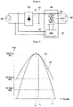
- Fig. 7 is a view illustrating a state in which output power is changed according to a DC link voltage.
- a first resonance curve 710 represents a resonance curve according to a DC link voltage
- a second resonance curve 720 represents a resonance curve according to a voltage adjusted by a DC/DC converter 600. It is confirmed through Fig. 7 that, as the DC/DC converter 600 adjusts a DC link voltage, the output power is adjustable.
- the induction heat cooking apparatus may have an effect in which the low power is constantly outputted by using the same resonance curve.
- Fig. 8 is a circuit diagram of an induction heat cooking apparatus according to an example not being claimed.
- An induction heat cooking apparatus may include at least one of a rectifier 120, a DC link capacitor 130, an inverter 140, a heating coil 150, a resonance capacitor 160, an SMPS 170, a switch 810, a charger 820, a battery 830, and a DC/DC converter 840.
- the switch 810 may select a power supply source.
- the switch 810 may be disposed at a DC link terminal.
- the switch 810 may select one of power stored in an input AC power source 110 and a battery 830 as a power supply source. That is, the switch 810 may be connected to one of the external power source 110 and the battery 830.
- the switch 810 when the switch 810 is connected to a contact point b, the switch 810 may be connected to the external power source 110.
- the switch 810 may be connected to the battery 830.
- the switch 810 may correspond to a three-terminal relay.
- a common (COM) terminal may be connected to the inverter 140
- a normal open (NO) terminal may be connected to the battery 830
- a normal close (NC) terminal may be connected to the external power source 110.
- the induction heat cooking apparatus heats a cooking device by using the external power source 110 when a separate command is not inputted.
- the induction heat cooking apparatus heats the cooking device by the battery 830 only when an event occurs.
- the event may be an operation command in a wireless mode or a command for adjusting a firepower level below a reference level.
- An operation of the switch 810 is controlled by a driving unit (not shown). Also, the driving unit (not shown) may control an operation of each of the components of Fig. 8 .
- the inverter 140 may supply current to the heating coil 150 by using a voltage supplied from the power supply source connected by the switch 810.
- the power supply source connected by the switch 810 may represent the external power source 110 or the battery 830.
- the heating coil 150 may generate magnetic fields to heat the cooking device.
- the charger 820 may introduce the power into the battery 830. Particularly, the charger 820 may acquire power from the external power source 110 to charge the battery 830.
- the charger 820 may charge the battery 830 while the switch 810 is connected to the external power source 110. That is, the charger 820 may charge the battery 830 while the induction heat cooking apparatus operates in a wired mode and may stop the charging of the battery 830 while the induction heat cooking apparatus operates in a wireless mode.
- the battery 830 stores power.
- the battery 830 may store power introduced through the charger 820 and use the stored power whenever the power needs. Particularly, the battery 830 may be charged while the switch 810 is connected to the external power source 110. On the other hand, when the battery 830 is connected to the switch 810, the battery 830 may be discharged to supply a voltage to the inverter 140. Thus, the battery 830 may supply power to the inverter 140 even though the induction heat cooking apparatus is not connected to the external power source 110. Thus, the induction heat cooking apparatus that operates in the wireless mode may be realized through the battery 830. As described above, according to the example not being claimed, the induction heat cooking apparatus may use one inverter topology to realize all of the wired operation and the wireless operation. That is, the wired/wireless inverter topology may be shared. This will be described later in detail.
- the battery 830 may be a component for allowing the induction heat cooking apparatus to constantly output low power. That is, the battery 830 may output a low-voltage DC voltage so that the induction heat cooking apparatus constantly linearly outputs the low power. In this case, the induction heat cooking apparatus may constantly supply the lower power than the output power according to an IGBT maximum switching frequency.
- the battery 830 may be a lithium ion battery.
- constant current (CC) charging may start. That is, while a voltage increases, constant current may be continuously supplied to charge the battery 830. Thereafter, when reaching a target charging voltage, the battery 830 may perform constant voltage (CV) charging. This is to charge remainder after the fast charging. While the CV charging is performed, the voltage may be constantly maintained. As the charging runs out, the current may be reduced.
- CV constant voltage
- the DC/DC converter 840 may convert the voltage supplied from the battery 830. Particularly, the DC/DC converter 840 may convert the voltage supplied from the battery 830 and be connected to the SMPS 170. Thus, it may prevent an operation of the SMPS 170 from being stopped.
- the SMPS 170 may supply power required for operating the inverter 140.
- the connection between the inverter 140 and the power supply source (the external power source 110) or the battery 830 may be stopped according to the operation of the switch 810. In this case, the stop of the operation of the inverter 140 may occur.
- the SMPS 170 may supply the constant power to the inverter 140 to prevent the operation of the inverter 140 from being stopped. For example, the SMPS 170 may supply DC power of about 12 V or about 5 V to the inverter 140.
- Fig. 9 is a circuit diagram of an induction heat cooking apparatus according to another example not being claimed.
- the induction heat cooking apparatus may further include a diode 910 in the circuit diagram of Fig. 8 .
- the diode 910 may have one side connected to a switch 810 and the other side connected to a connection point between a battery 830 and a DC/DC converter 840.
- the diode 910 may prevent an external power source 110 and the battery 830 from being short-circuited with each other. If the external power source 110 and the battery 830 are short-circuited with each other, the circuit may be damaged, or the battery 830 may be exploded.
- the diode 910 may be disposed on an outer terminal of the battery 830 to prevent the external power source 110 and the battery 830 from being short-circuited with each other when the switch 810 is normally driven or abnormally driven due to breakdown.
- the short circuit between the external power source and the battery may be mechanically/electrically prevented to secure safety.
- the rest components except for the diode 910 are the same as those of Fig. 8 .
- the induction heat cooking apparatus which is secured in safety and is capable of operating in the wired/wireless manner, may be provided.
- Fig. 10 is a structural view for explaining a method for operating the induction heat cooking apparatus according to an embodiment.
- the induction heat cooking apparatus includes a firepower adjustment unit 1010 and a driving unit 1030.
- the induction heat cooking apparatus according to the embodiment may include all of a firepower adjustment unit, an operation mode setting unit 1020, and a driving unit 1030.
- the method for operating the induction heat cooking apparatus will be described as an example in case of the induction heat cooking apparatus of Fig. 10 according to the embodiment, which may include all of the firepower adjustment unit, the operation mode setting unit 1020, and the driving unit 1030. However, this may be merely illustrative for explaining the abovementioned embodiments and also be applied to other embodiments. Also, although the firepower adjustment unit 1010 and the operation mode setting unit 1020 are connected to the driving unit 1030, and the driving unit 1030 is connected to the switch 810 and the inverter 140 in Fig. 10 , this may be merely illustrative. Each of the components may have a configuration different from that of each of the components of Fig. 10 . For example, the firepower adjustment unit 1010, the operation mode setting unit 1020, and the driving unit 1030 may be provided in the inverter 140.
- the firepower adjustment unit 1010 may be a component for setting heat applied from the induction heat cooking apparatus to the cooking device.
- the heat applied to the cooking device may be divided into N firepower levels.
- the N firepower levels may include a first firepower level, a second firepower level,..., an N-th firepower level.
- the applied heat may increase in firepower.
- the firepower adjustment unit 1010 may receive a firepower adjustment command for selecting one of the first firepower level to the N-th firepower level.
- the firepower adjustment command may represent a command for adjusting the firepower levels of the heat applied from the induction heat cooking apparatus to the cooking device.
- the operation mode setting unit 1020 is a component for setting the operation modes of the induction heat cooking apparatus to one of the wired mode or the wireless mode.
- the operation mode setting unit 1020 may receive the command for selecting one of the wired mode and the wireless mode.
- the induction heat cooking apparatus uses power supplied from the external power source 110.
- the induction heat cooking apparatus uses power supplied from the battery 830.
- the driving unit 1030 may control a connection position of the switch 810 according to the operation mode set through the operation mode setting unit 1020.
- the driving unit 1030 controls an overall operation of each of the components constituting the induction heat cooking apparatus. Particularly, the driving unit 1030 may control the switch 810 and the inverter 140.
- the driving unit 1030 may control the switch 810 and the inverter 140 so that heat corresponding to the firepower level set through the firepower adjustment unit 1010 is applied to the cooking device. That is, the driving unit 1030 controls a connection position of the switch 810 according to the firepower levels. Also, the driving unit 1030 may control an amount of current supplied from the inverter 140 to the heating coil according to the firepower level.
- the driving unit 1030 may control the switch 810 to operate in the mode set through the operation mode setting unit 1020. Particularly, when the driving unit 1030 is set to the wired mode, the switch 810 may be connected to a terminal of the external power source 110. When the driving unit 1030 is set to the wireless mode, the switch 810 may be connected to a terminal of the battery 830.
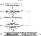
- Fig. 11 is a flowchart of a method for operating the induction heat cooking apparatus according to another embodiment. Particularly, Fig. 11 is a flowchart of a method for operating the induction heat cooking apparatus according to the embodiment.
- An operation mode setting unit 1020 may receive a command for selecting one of a wired mode or a wireless mode (S11).
- a command for selecting one of the wired mode or the wireless mode is inputted according to convenience of a user.
- the operation mode setting unit 1020 may receive the command for selecting one of the wired mode and the wireless mode.
- the driving unit 1030 may determine whether the received command is the command for selecting the wired mode (S13).
- the driving unit 1030 may determine whether the command received through the operation mode setting unit 1020 is the command for selecting the wired mode or the command for selecting the wireless mode.
- the driving unit 1030 controls the switch 801 so that the switch 810 is connected to a contact point a (S21).
- the driving unit 1030 controls the switch 810 so that the switch 810 is connected to the contact point a.
- the contact point a is a terminal connected to the battery 830. The operation in which the switch 810 is connected to the contact point a to heat the cooking device will be described below.
- the driving unit 1030 receives a firepower adjustment command through the firepower adjustment unit 1010 (S15).
- the firepower adjustment unit 1010 may receive the firepower adjustment command for selecting one of the first firepower level to the N-th firepower level.
- the reference symbol N that represents the level of the firepower levels may vary according to a design of the induction heat cooking apparatus.
- the driving unit 1030 may determine whether the firepower level according to the received command is above a predetermined reference level (S17).
- the first firepower level to N-th firepower level may be divided into levels using the external power source 110 and levels using the battery 830 with respect tot eh preset reference level. Particularly, in the firepower level above the preset reference level, the induction heat cooking apparatus heats the cooking device by using the external power source 110. On the other hand, in the firepower level below the preset reference level, the induction heat cooking apparatus heats the cooking device by using the battery 830. As described above, a reason in which the battery 830 is used in the firepower level below the reference level is for constantly outputting low power without repeatedly performing turn on/off of the power.
- the reference level may be determined according to output power due to an IGBT maximum switching frequency.
- the driving unit 1030 may acquire a level for dividing the firepower levels in which power higher than the output power is outputted and the firepower levels in which power lower than the output power is outputted according to the IGBT maximum switching frequency to set the acquired level as the reference level.
- the driving unit 1030 determines whether the firepower adjusted through the preset reference level according to the above-described method is above the reference level.
- the driving unit 1030 controls the switch 810 so that the switch 810 is connected to a contact point b (S19).
- the contact point b is a terminal connected tot eh external power source 110.
- the driving unit 1030 controls the switch 810 so that the switch 810 is connected to a contact point a (S21).
- the contact point a is a terminal connected to the battery 830.
- FIG. 12A to 12B are view illustrating an operation state when a switch of the induction heat cooking apparatus is connected to the external power source according to the embodiments
- Figs. 13A to 13B are view illustrating an operation state when the switch of the induction heat cooking apparatus is connected to the battery according to the embodiments.
- a component expressed as a solid line of Figs 12B and 13B and a component expressed as a dotted line of Figs. 12B and 13B are shown by distinguishing an operating component from a component that does not operate according to the connection position of the switch.
- the driving unit 1030 may control the switch 810 so that the switch 810 is connected to the contact point b as illustrated in Fig. 12A .
- the switch 810 is connected to the terminal of the external power source 110.
- the inverter 140 and the external power source 110 are connected to each other, and the connection between the inverter 140 and the battery 830 may be prevented.
- an AC voltage supplied from the external power source 110 is introduced into a rectifier 120, and a DC voltage outputted through the rectifier 120 is supplied to the inverter 140.
- the inverter 140 converts the supplied DC voltage into an AC voltage to supply the converted AC voltage to the heating coil 150.
- the AC voltage is supplied from the inverter 140, current flows through the heating coil 150.
- magnetic fields may be generated in the heating coil 150 to heat the cooking device.
- the external power source 110 may supply a voltage to a charger 820 as well as the rectifier 120.
- the charger 820 charges the battery 830 by using the voltage supplied from the external power source 110.
- the battery 830 may store the power supplied through the external power source 110.
- the driving unit 1030 may control the switch 810 so that the switch 810 is connected to the contact point a.
- the switch 810 is connected to the terminal of the battery 830.
- the inverter 140 When the switch 810 is connected to the battery 830, as illustrated in Fig. 13B , the inverter 140 is connected to the battery 830, and the connection between the inverter 140 and the external power source 110 may be prevented.
- the battery 830 supplies the DC voltage to the inverter 140.
- the inverter 140 allows the current to flow through the heating coil 150 by using the supplied DC voltage, and the heating coil 150 generates the magnetic fields due to the flowing of the current to heat the cooking device.
- the battery 830 may supply a voltage for outputting the power lower than the output power according to the IGBT maximum switching frequency to the inverter 140. As described above, the battery 830 constantly outputs the low voltage, and the induction heat cooking apparatus constantly output the low power to provide a function for keeping warm the cooking device.
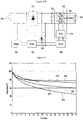
- FIG. 14 is experimental data showing an effect in which the induction heat cooking apparatus keeps warm the cooking device by using a battery according to an embodiment.
- the graph of Fig. 14 illustrates a variation in temperature of contents when the induction heat cooking apparatus outputs the low power to heat the cooking device containing a content having a temperature of about 100 degrees.
- the graph illustrated in Fig. 14 is an illustrative graph in a case in which the content is water.
- a reference dotted-line 1400 illustrated in Fig. 14 represents a minimum temperature (about 60 degrees) of the content, which is measured when the induction heat cooking apparatus outputs the low power by using the external power source 110, and the power turn-off operation is repeated. That is, when the induction heat cooking apparatus uses the external power source 110, the temperature may drop down to about 40 degrees.
- a reference graph 1410 is a graph that illustrates a variation in temperature of the content when the content of the cooking device heated up to a temperature of about 100 degrees is stored at room temperature.
- the temperature drop by a temperature of about 55 degrees may occur, and thus, the content may be measured at a temperature of about 45 degrees.
- the induction heat cooking apparatus keeps warm the contents when the external power source 110 is used.
- First to third graphs 1421, 1422, and 1423 are graphs illustrating a variation in temperature when the induction heat cooking apparatus heats the cooking device by using the battery 830.
- the first graph 1421 illustrates a variation in temperature when power of about 300 W (about 32 kHz) is outputted to heat the cooking device
- the second graph 1422 illustrates a variation in temperature when power of about 200 W (about 37 kHz) is outputted to heat the cooking device
- the third graph 1423 illustrates a variation in temperature when power of about 100 W (about 50 kHz) is outputted to heat the cooking device.
- the content is measured at temperatures of about 77 degrees Celsius, about 73 degrees, and about 60 degrees as about 30 minutes elapses. That is, the temperature of the content drops down by temperatures of about 23 degrees, about 27 degrees, and about 40 degrees.
- the induction heat cooking apparatus may include the battery 830 to provide the function of keeping ward the content.
- the induction heat cooking apparatus that operates in the wireless mode as well as the wired mode may be provided.
- the induction heat cooking apparatus that is easily converted into the wired mode or the wireless mode according to the user's needs to operate may be provided.
- the induction heat cooking apparatus that is capable of operating in the wired mode or the wireless mode by using the one common inverter may be provided.
- the induction heat cooking apparatus that constantly outputs the low power without repeatedly turning on/off the power may be provided.
- the wired/wireless operating induction heat cooking apparatus that is capable of preventing the risk of explosion of the battery may be provided.
Landscapes
- Physics & Mathematics (AREA)
- Electromagnetism (AREA)
- Induction Heating Cooking Devices (AREA)
Claims (13)
- Appareil de cuisson à induction comprenant :un redresseur (120) configuré pour convertir une tension alternative fournie par une source d'alimentation externe (110) en une tension continue ;une batterie (830) configurée pour stocker de l'énergie ;un commutateur (810) connecté à l'un du redresseur (120) et de la batterie (830) ;une unité de réglage de puissance de feu (1010) configurée pour recevoir une instruction pour régler un niveau de puissance de feu,une unité d'entraînement (1030) configurée pour commander le commutateur (810) de sorte que le commutateur (810) est connecté au redresseur (120) lorsque le niveau de puissance de feu réglé est au-dessus d'un niveau de référence prédéfini et est connecté à la batterie (830) lorsque le niveau de puissance de feu réglé est au-dessous du niveau de référence;un onduleur (140) configuré pour convertir une tension fournie par une source d'alimentation électrique connectée par le commutateur et fournir la tension convertie à une bobine de chauffage (150) ; etla bobine de chauffage (150) étant configurée pour générer des champs magnétiques par la tension fournie par l'onduleur (140) pour chauffer un dispositif de cuisson.
- Appareil de cuisson à induction selon la revendication 1, comprenant en outre :une unité de réglage de mode de fonctionnement (1020) configurée pour recevoir une instruction pour sélectionner l'un d'un mode filaire et d'un mode sans fil ; etdans lequel l'unité d'entraînement (1030) est configurée pour commander le commutateur (810) de sorte que le commutateur (810) est connecté au redresseur (120) lorsque l'instruction pour sélectionner le mode filaire est reçue et est connecté à la batterie (830) lorsque l'instruction pour sélectionner le mode sans fil est reçue.
- Appareil de cuisson à induction selon la revendication 2, dans lequel de l'énergie de la batterie (830) est chargée par la réception d'une énergie à partir de la source d'alimentation externe (110) tandis que le commutateur est connecté au redresseur (120).
- Appareil de cuisson à induction selon la revendication 1, 2 ou 3, dans lequel la batterie (830) fournit l'énergie chargée à l'onduleur (140) tandis que le commutateur (810) est connecté à la batterie (830).
- Appareil de cuisson à induction selon la revendication 1, dans lequel l'onduleur (140) entraîne un dispositif de commutation à transistor bipolaire à grille isolée, IGBT, à fournir du courant à la bobine de chauffage (150).
- Appareil de cuisson à induction selon la revendication 5, dans lequel le niveau de référence est déterminé par une puissance de sortie selon une fréquence de commutation maximale de l'IGBT.
- Appareil de cuisson à induction selon la revendication 6, dans lequel la batterie (830) fournit une tension pour délivrer en sortie une puissance inférieure à la puissance de sortie selon la fréquence de commutation maximale de l'IGBT.
- Appareil de cuisson à induction selon l'une quelconque des revendications 1 à 7, comprenant en outre une diode (910) pour empêcher la source d'alimentation externe (110) et la batterie (830) d'être court-circuitées l'une avec l'autre.
- Appareil de cuisson à induction selon l'une quelconque des revendications 1 à 8, dans lequel le commutateur (810) comprend un commutateur relais à trois bornes, et le commutateur relais à trois bornes possède une borne commune, COM, connectée à l'onduleur (140), une borne ouverte normale, NO, connectée à la batterie (830) et une borne fermée normale, NC, connectée au redresseur (120).
- Procédé de fonctionnement d'un appareil de cuisson à induction, le procédé comprenant :la réception (S11) d'une instruction pour sélectionner l'un d'un mode filaire et d'un mode sans fil ;la commande (S21) d'un commutateur de sorte que le commutateur est connecté à une batterie lorsque l'instruction pour sélectionner le mode sans fil est reçue ;la réception (S15) d'une instruction pour régler un niveau de puissance de feu lorsque l'instruction pour sélectionner le mode filaire est reçue ;la commande (S21) du commutateur de sorte que le commutateur est connecté à la batterie lorsque le niveau de puissance de feu réglé est au-dessous d'un niveau de référence prédéfini°;la commande (S19) du commutateur de sorte que le commutateur est connecté à un redresseur lorsque le niveau de puissance de feu réglé est au-dessus du niveau de référence prédéfini ;la fourniture d'une tension fournie par une source d'alimentation électrique connectée par le commutateur à une bobine de chauffage ; etla génération de champs magnétiques en raison de la circulation du courant à travers la bobine de chauffage pour chauffer un dispositif de cuisson.
- Procédé selon la revendication 10, comprenant en outre la charge de la batterie par l'intermédiaire de la source d'alimentation externe lorsque le commutateur est connecté au redresseur.
- Procédé selon la revendication 11, comprenant en outre la fourniture d'énergie chargée dans la batterie à la bobine de chauffage lorsque le commutateur est connecté à la batterie.
- Procédé selon la revendication 10, comprenant en outre le réglage du niveau de référence prédéfini sur la base d'une puissance de sortie selon une fréquence de commutation maximale d'un IGBT.
Priority Applications (1)
| Application Number | Priority Date | Filing Date | Title |
|---|---|---|---|
| EP19177841.4A EP3567986B1 (fr) | 2016-12-15 | 2017-12-13 | Appareil de cuisson à induction et son procédé de commande |
Applications Claiming Priority (1)
| Application Number | Priority Date | Filing Date | Title |
|---|---|---|---|
| KR1020160171801A KR20180069532A (ko) | 2016-12-15 | 2016-12-15 | 전자 유도 가열 조리기 및 그의 동작 방법 |
Related Child Applications (2)
| Application Number | Title | Priority Date | Filing Date |
|---|---|---|---|
| EP19177841.4A Division EP3567986B1 (fr) | 2016-12-15 | 2017-12-13 | Appareil de cuisson à induction et son procédé de commande |
| EP19177841.4A Division-Into EP3567986B1 (fr) | 2016-12-15 | 2017-12-13 | Appareil de cuisson à induction et son procédé de commande |
Publications (3)
| Publication Number | Publication Date |
|---|---|
| EP3337294A1 EP3337294A1 (fr) | 2018-06-20 |
| EP3337294B1 EP3337294B1 (fr) | 2019-07-24 |
| EP3337294B2 true EP3337294B2 (fr) | 2022-05-11 |
Family
ID=60915188
Family Applications (2)
| Application Number | Title | Priority Date | Filing Date |
|---|---|---|---|
| EP17207098.9A Active EP3337294B2 (fr) | 2016-12-15 | 2017-12-13 | Appareil de cuisson à induction et son procédé de commande |
| EP19177841.4A Active EP3567986B1 (fr) | 2016-12-15 | 2017-12-13 | Appareil de cuisson à induction et son procédé de commande |
Family Applications After (1)
| Application Number | Title | Priority Date | Filing Date |
|---|---|---|---|
| EP19177841.4A Active EP3567986B1 (fr) | 2016-12-15 | 2017-12-13 | Appareil de cuisson à induction et son procédé de commande |
Country Status (3)
| Country | Link |
|---|---|
| US (3) | US10917947B2 (fr) |
| EP (2) | EP3337294B2 (fr) |
| KR (1) | KR20180069532A (fr) |
Families Citing this family (15)
| Publication number | Priority date | Publication date | Assignee | Title |
|---|---|---|---|---|
| KR102139357B1 (ko) * | 2018-09-04 | 2020-07-29 | 엘지전자 주식회사 | 과열 방지 메커니즘을 갖춘 정수기 |
| KR102137036B1 (ko) * | 2018-09-04 | 2020-07-23 | 엘지전자 주식회사 | Emi 저감 성능이 개선된 유도 가열 방식의 전자 장치 |
| KR102137035B1 (ko) * | 2018-09-04 | 2020-07-23 | 엘지전자 주식회사 | Emi 저감 성능이 개선된 유도 가열 방식의 전자 장치 |
| KR102672130B1 (ko) * | 2018-11-01 | 2024-06-05 | 삼성전자주식회사 | 외부 전자 장치로부터 전원을 공급받는 전자 장치 및 방법 |
| KR102201189B1 (ko) * | 2019-09-05 | 2021-01-08 | 엘지전자 주식회사 | 유도 가열 장치 |
| KR102888178B1 (ko) | 2020-05-06 | 2025-11-18 | 엘지전자 주식회사 | 유도 가열 장치 및 유도 가열 장치의 제어 방법 |
| EP4037432B1 (fr) * | 2021-01-27 | 2026-01-07 | LG Electronics Inc. | Dispositif de chauffage par induction et procédé de commande de dispositif de chauffage par induction |
| US11825987B2 (en) * | 2021-03-18 | 2023-11-28 | Kenyon International, Inc. | DC cooking appliance |
| US12379102B2 (en) * | 2021-03-23 | 2025-08-05 | Weber-Stephen Products Llc | Cooking chamber lighting for pellet grills |
| KR102593479B1 (ko) * | 2021-07-16 | 2023-10-24 | 엘지전자 주식회사 | 유도 가열 방식의 쿡탑 |
| KR20230033361A (ko) * | 2021-09-01 | 2023-03-08 | 삼성전자주식회사 | 조리 장치 및 그 제어 방법 |
| US20250194855A1 (en) * | 2022-02-28 | 2025-06-19 | Kenyon International, Inc. | Dc cooking appliance |
| KR102937886B1 (ko) * | 2022-05-02 | 2026-03-11 | 엘지전자 주식회사 | 조리기기 |
| KR102852967B1 (ko) * | 2022-08-30 | 2025-09-01 | 주식회사 경동나비엔 | 유도 가열 장치 |
| KR20250014678A (ko) * | 2023-07-21 | 2025-02-03 | 삼성전자주식회사 | 조리기기 |
Citations (16)
| Publication number | Priority date | Publication date | Assignee | Title |
|---|---|---|---|---|
| JPH046790A (ja) † | 1990-04-24 | 1992-01-10 | Matsushita Electric Ind Co Ltd | 調理機器 |
| JPH04292893A (ja) † | 1991-03-20 | 1992-10-16 | Matsushita Electric Ind Co Ltd | 高周波加熱装置 |
| JPH07235372A (ja) † | 1994-02-22 | 1995-09-05 | Zojirushi Corp | ハイパワー調理器 |
| JPH081597Y2 (ja) † | 1990-02-16 | 1996-01-17 | 株式会社トーキン | 電磁調理器 |
| JPH11111442A (ja) † | 1997-10-06 | 1999-04-23 | Matsushita Electric Ind Co Ltd | 誘導加熱装置 |
| JP2004016416A (ja) † | 2002-06-14 | 2004-01-22 | Toshiba Corp | 炊飯器 |
| JP2005149990A (ja) † | 2003-11-18 | 2005-06-09 | Toshiba Home Technology Corp | 加熱調理器 |
| JP2006278192A (ja) † | 2005-03-30 | 2006-10-12 | Tokyo Electric Power Co Inc:The | 誘導加熱調理器 |
| JP2008004416A (ja) † | 2006-06-23 | 2008-01-10 | Toshiba Corp | 加熱調理器 |
| US20100244571A1 (en) † | 2009-03-27 | 2010-09-30 | American Power Conversion Corporation | System and method for changing power states of a power device |
| US20100315849A1 (en) † | 2009-06-16 | 2010-12-16 | American Power Conversion Corporation | Power supply control |
| JP2012003915A (ja) † | 2010-06-16 | 2012-01-05 | Panasonic Corp | 誘導加熱調理器 |
| JP2014116124A (ja) † | 2012-12-07 | 2014-06-26 | Panasonic Corp | 誘導加熱調理器 |
| CN104135784A (zh) † | 2014-07-07 | 2014-11-05 | 江西赛特新能源科技有限公司 | 一种适用于火锅电磁炉的锂电池供电系统 |
| JP2014229423A (ja) † | 2013-05-21 | 2014-12-08 | パナソニック株式会社 | 誘導加熱調理器 |
| WO2015167568A1 (fr) † | 2014-05-01 | 2015-11-05 | Schneider Electric It Corporation | Commande d'alimentation électrique |
Family Cites Families (19)
| Publication number | Priority date | Publication date | Assignee | Title |
|---|---|---|---|---|
| US3697717A (en) * | 1971-11-19 | 1972-10-10 | Gen Electric | Induction cooking appliance with multicylinder power circuits |
| JPH0815972A (ja) | 1994-07-01 | 1996-01-19 | Hitachi Ltd | 画像形成システム |
| JP2957104B2 (ja) * | 1994-12-29 | 1999-10-04 | 株式会社アイ・ヒッツ研究所 | 単相入力整流回路 |
| EP1325666A4 (fr) * | 2000-08-18 | 2007-03-21 | Luxine Inc | Systeme et procede de chauffage par induction et de commande presentant une fiabilite elevee et de meilleures caracteristiques de performance |
| US6696675B2 (en) | 2001-08-10 | 2004-02-24 | Tocco, Inc. | Induction heating system for internal combustion engine |
| KR100661226B1 (ko) * | 2005-12-02 | 2006-12-22 | 엘지전자 주식회사 | 전기조리기의 부하 감지장치 및 방법 |
| NL1036928C2 (en) * | 2009-05-06 | 2010-11-09 | Foremost Bv | Device for frothing milk or other milk based liquids. |
| DE102009047185B4 (de) * | 2009-11-26 | 2012-10-31 | E.G.O. Elektro-Gerätebau GmbH | Verfahren und Induktionsheizeinrichtung zum Ermitteln einer Temperatur eines mittels einer Induktionsheizspule erwärmten Kochgefäßbodens |
| US9590444B2 (en) * | 2009-11-30 | 2017-03-07 | Broadcom Corporation | Device with integrated wireless power receiver configured to make a charging determination based on a level of battery life and charging efficiency |
| KR101148682B1 (ko) | 2010-10-08 | 2012-05-25 | 배영란 | 데이터백업용 무배터리형 무정전 전원장치 |
| WO2013146794A1 (fr) * | 2012-03-26 | 2013-10-03 | 有限会社エフ・テイ・イノベーション | Plateau pour chauffage/cuisson par induction électromagnétique et ensemble de plats chauffants par induction électromagnétique |
| CN203575847U (zh) * | 2012-09-18 | 2014-05-07 | 新加坡大华集团 | 经由热来作发型设计的被加热的发型设计装置 |
| JP2014099253A (ja) | 2012-11-13 | 2014-05-29 | Panasonic Corp | 加熱調理器 |
| KR102009354B1 (ko) * | 2012-11-26 | 2019-08-09 | 엘지전자 주식회사 | 전자 유도 가열 조리기 및 이의 구동 방법 |
| GB2520922A (en) * | 2013-10-15 | 2015-06-10 | Trung Van Ta | Battery powered food or beverage induction heater |
| RU2666793C2 (ru) * | 2013-10-30 | 2018-09-12 | Конинклейке Филипс Н.В. | Тепловой барьер для беспроводной передачи мощности |
| JP6057948B2 (ja) | 2014-06-16 | 2017-01-11 | 三菱電機株式会社 | 誘導加熱調理器、および電力管理システム |
| KR101968553B1 (ko) * | 2017-01-04 | 2019-04-12 | 엘지전자 주식회사 | Wpt 구현 가능한 전자 유도 가열 조리기 및 pfc 전력 변환 장치 |
| KR101999511B1 (ko) * | 2017-08-04 | 2019-07-11 | 엘지전자 주식회사 | 유도가열조리기 및 그의 동작 방법 |
-
2016
- 2016-12-15 KR KR1020160171801A patent/KR20180069532A/ko not_active Ceased
-
2017
- 2017-12-13 EP EP17207098.9A patent/EP3337294B2/fr active Active
- 2017-12-13 EP EP19177841.4A patent/EP3567986B1/fr active Active
- 2017-12-15 US US15/843,862 patent/US10917947B2/en active Active
-
2021
- 2021-01-05 US US17/141,749 patent/US12016104B2/en active Active
-
2024
- 2024-05-15 US US18/664,473 patent/US20240298386A1/en active Pending
Patent Citations (16)
| Publication number | Priority date | Publication date | Assignee | Title |
|---|---|---|---|---|
| JPH081597Y2 (ja) † | 1990-02-16 | 1996-01-17 | 株式会社トーキン | 電磁調理器 |
| JPH046790A (ja) † | 1990-04-24 | 1992-01-10 | Matsushita Electric Ind Co Ltd | 調理機器 |
| JPH04292893A (ja) † | 1991-03-20 | 1992-10-16 | Matsushita Electric Ind Co Ltd | 高周波加熱装置 |
| JPH07235372A (ja) † | 1994-02-22 | 1995-09-05 | Zojirushi Corp | ハイパワー調理器 |
| JPH11111442A (ja) † | 1997-10-06 | 1999-04-23 | Matsushita Electric Ind Co Ltd | 誘導加熱装置 |
| JP2004016416A (ja) † | 2002-06-14 | 2004-01-22 | Toshiba Corp | 炊飯器 |
| JP2005149990A (ja) † | 2003-11-18 | 2005-06-09 | Toshiba Home Technology Corp | 加熱調理器 |
| JP2006278192A (ja) † | 2005-03-30 | 2006-10-12 | Tokyo Electric Power Co Inc:The | 誘導加熱調理器 |
| JP2008004416A (ja) † | 2006-06-23 | 2008-01-10 | Toshiba Corp | 加熱調理器 |
| US20100244571A1 (en) † | 2009-03-27 | 2010-09-30 | American Power Conversion Corporation | System and method for changing power states of a power device |
| US20100315849A1 (en) † | 2009-06-16 | 2010-12-16 | American Power Conversion Corporation | Power supply control |
| JP2012003915A (ja) † | 2010-06-16 | 2012-01-05 | Panasonic Corp | 誘導加熱調理器 |
| JP2014116124A (ja) † | 2012-12-07 | 2014-06-26 | Panasonic Corp | 誘導加熱調理器 |
| JP2014229423A (ja) † | 2013-05-21 | 2014-12-08 | パナソニック株式会社 | 誘導加熱調理器 |
| WO2015167568A1 (fr) † | 2014-05-01 | 2015-11-05 | Schneider Electric It Corporation | Commande d'alimentation électrique |
| CN104135784A (zh) † | 2014-07-07 | 2014-11-05 | 江西赛特新能源科技有限公司 | 一种适用于火锅电磁炉的锂电池供电系统 |
Also Published As
| Publication number | Publication date |
|---|---|
| US10917947B2 (en) | 2021-02-09 |
| KR20180069532A (ko) | 2018-06-25 |
| EP3567986A1 (fr) | 2019-11-13 |
| US20240298386A1 (en) | 2024-09-05 |
| EP3337294B1 (fr) | 2019-07-24 |
| EP3337294A1 (fr) | 2018-06-20 |
| EP3567986B1 (fr) | 2020-08-19 |
| US20210127463A1 (en) | 2021-04-29 |
| US20180177000A1 (en) | 2018-06-21 |
| US12016104B2 (en) | 2024-06-18 |
Similar Documents
| Publication | Publication Date | Title |
|---|---|---|
| EP3337294B2 (fr) | Appareil de cuisson à induction et son procédé de commande | |
| US12414205B2 (en) | Induction heat cooking apparatus to implement WPT and PFC power converter | |
| KR102676852B1 (ko) | 유도 가열 장치 | |
| US11271441B2 (en) | Wireless power transfer apparatus, wireless power reception apparatus, and system including the same | |
| US11943858B2 (en) | Induction heating apparatus and method of controlling the same | |
| KR102430537B1 (ko) | 전자 유도 가열 조리기 및 그의 동작 방법 | |
| KR101949562B1 (ko) | 유도 가열 장치 | |
| KR20200000417A (ko) | 전자 유도 가열 조리기 및 그의 동작 방법 | |
| KR20190138153A (ko) | 휴대용 전기레인지 | |
| US20230354484A1 (en) | Cooking appliance | |
| ES2754793A1 (es) | Dispositivo de Aparato de Cocción | |
| KR20230123740A (ko) | 유도 가열 방식의 쿡탑 | |
| KR20090048684A (ko) | 유도가열 조리기기의 전원 제어장치 및 방법 | |
| KR102254222B1 (ko) | 자려발진 방식의 무선 충전 및 유도 가열 장치 | |
| ES2764740A1 (es) | Dispositivo de aparato de cocción | |
| EP4535924A1 (fr) | Table de cuisson du type a chauffage par induction | |
| EP4280817A1 (fr) | Appareil de cuisson | |
| KR20210081053A (ko) | 전자 유도 가열 조리기기 및 그의 구동 모듈 | |
| CN204539517U (zh) | 电磁加热系统及其开关管的开通控制装置 | |
| KR102292255B1 (ko) | 전자 유도 가열 조리기기 및 그의 구동 모듈 | |
| KR102782747B1 (ko) | 전기 쿡탑 | |
| US20230171856A1 (en) | Induction heating type cooktop | |
| KR20210081071A (ko) | 전자 유도 가열 조리기기 및 그의 제어 방법 |
Legal Events
| Date | Code | Title | Description |
|---|---|---|---|
| PUAI | Public reference made under article 153(3) epc to a published international application that has entered the european phase |
Free format text: ORIGINAL CODE: 0009012 |
|
| STAA | Information on the status of an ep patent application or granted ep patent |
Free format text: STATUS: REQUEST FOR EXAMINATION WAS MADE |
|
| 17P | Request for examination filed |
Effective date: 20180113 |
|
| AK | Designated contracting states |
Kind code of ref document: A1 Designated state(s): AL AT BE BG CH CY CZ DE DK EE ES FI FR GB GR HR HU IE IS IT LI LT LU LV MC MK MT NL NO PL PT RO RS SE SI SK SM TR |
|
| AX | Request for extension of the european patent |
Extension state: BA ME |
|
| RBV | Designated contracting states (corrected) |
Designated state(s): AL AT BE BG CH CY CZ DE DK EE ES FI FR GB GR HR HU IE IS IT LI LT LU LV MC MK MT NL NO PL PT RO RS SE SI SK SM TR |
|
| RIC1 | Information provided on ipc code assigned before grant |
Ipc: H05B 6/06 20060101AFI20181218BHEP |
|
| GRAP | Despatch of communication of intention to grant a patent |
Free format text: ORIGINAL CODE: EPIDOSNIGR1 |
|
| STAA | Information on the status of an ep patent application or granted ep patent |
Free format text: STATUS: GRANT OF PATENT IS INTENDED |
|
| INTG | Intention to grant announced |
Effective date: 20190204 |
|
| GRAS | Grant fee paid |
Free format text: ORIGINAL CODE: EPIDOSNIGR3 |
|
| GRAA | (expected) grant |
Free format text: ORIGINAL CODE: 0009210 |
|
| STAA | Information on the status of an ep patent application or granted ep patent |
Free format text: STATUS: THE PATENT HAS BEEN GRANTED |
|
| AK | Designated contracting states |
Kind code of ref document: B1 Designated state(s): AL AT BE BG CH CY CZ DE DK EE ES FI FR GB GR HR HU IE IS IT LI LT LU LV MC MK MT NL NO PL PT RO RS SE SI SK SM TR |
|
| REG | Reference to a national code |
Ref country code: GB Ref legal event code: FG4D |
|
| REG | Reference to a national code |
Ref country code: CH Ref legal event code: EP |
|
| REG | Reference to a national code |
Ref country code: DE Ref legal event code: R096 Ref document number: 602017005539 Country of ref document: DE |
|
| REG | Reference to a national code |
Ref country code: AT Ref legal event code: REF Ref document number: 1159875 Country of ref document: AT Kind code of ref document: T Effective date: 20190815 |
|
| REG | Reference to a national code |
Ref country code: IE Ref legal event code: FG4D |
|
| REG | Reference to a national code |
Ref country code: NL Ref legal event code: MP Effective date: 20190724 |
|
| REG | Reference to a national code |
Ref country code: LT Ref legal event code: MG4D |
|
| REG | Reference to a national code |
Ref country code: AT Ref legal event code: MK05 Ref document number: 1159875 Country of ref document: AT Kind code of ref document: T Effective date: 20190724 |
|
| PG25 | Lapsed in a contracting state [announced via postgrant information from national office to epo] |
Ref country code: NO Free format text: LAPSE BECAUSE OF FAILURE TO SUBMIT A TRANSLATION OF THE DESCRIPTION OR TO PAY THE FEE WITHIN THE PRESCRIBED TIME-LIMIT Effective date: 20191024 Ref country code: BG Free format text: LAPSE BECAUSE OF FAILURE TO SUBMIT A TRANSLATION OF THE DESCRIPTION OR TO PAY THE FEE WITHIN THE PRESCRIBED TIME-LIMIT Effective date: 20191024 Ref country code: SE Free format text: LAPSE BECAUSE OF FAILURE TO SUBMIT A TRANSLATION OF THE DESCRIPTION OR TO PAY THE FEE WITHIN THE PRESCRIBED TIME-LIMIT Effective date: 20190724 Ref country code: AT Free format text: LAPSE BECAUSE OF FAILURE TO SUBMIT A TRANSLATION OF THE DESCRIPTION OR TO PAY THE FEE WITHIN THE PRESCRIBED TIME-LIMIT Effective date: 20190724 Ref country code: FI Free format text: LAPSE BECAUSE OF FAILURE TO SUBMIT A TRANSLATION OF THE DESCRIPTION OR TO PAY THE FEE WITHIN THE PRESCRIBED TIME-LIMIT Effective date: 20190724 Ref country code: PT Free format text: LAPSE BECAUSE OF FAILURE TO SUBMIT A TRANSLATION OF THE DESCRIPTION OR TO PAY THE FEE WITHIN THE PRESCRIBED TIME-LIMIT Effective date: 20191125 Ref country code: HR Free format text: LAPSE BECAUSE OF FAILURE TO SUBMIT A TRANSLATION OF THE DESCRIPTION OR TO PAY THE FEE WITHIN THE PRESCRIBED TIME-LIMIT Effective date: 20190724 Ref country code: NL Free format text: LAPSE BECAUSE OF FAILURE TO SUBMIT A TRANSLATION OF THE DESCRIPTION OR TO PAY THE FEE WITHIN THE PRESCRIBED TIME-LIMIT Effective date: 20190724 Ref country code: LT Free format text: LAPSE BECAUSE OF FAILURE TO SUBMIT A TRANSLATION OF THE DESCRIPTION OR TO PAY THE FEE WITHIN THE PRESCRIBED TIME-LIMIT Effective date: 20190724 |
|
| PG25 | Lapsed in a contracting state [announced via postgrant information from national office to epo] |
Ref country code: ES Free format text: LAPSE BECAUSE OF FAILURE TO SUBMIT A TRANSLATION OF THE DESCRIPTION OR TO PAY THE FEE WITHIN THE PRESCRIBED TIME-LIMIT Effective date: 20190724 Ref country code: GR Free format text: LAPSE BECAUSE OF FAILURE TO SUBMIT A TRANSLATION OF THE DESCRIPTION OR TO PAY THE FEE WITHIN THE PRESCRIBED TIME-LIMIT Effective date: 20191025 Ref country code: RS Free format text: LAPSE BECAUSE OF FAILURE TO SUBMIT A TRANSLATION OF THE DESCRIPTION OR TO PAY THE FEE WITHIN THE PRESCRIBED TIME-LIMIT Effective date: 20190724 Ref country code: AL Free format text: LAPSE BECAUSE OF FAILURE TO SUBMIT A TRANSLATION OF THE DESCRIPTION OR TO PAY THE FEE WITHIN THE PRESCRIBED TIME-LIMIT Effective date: 20190724 Ref country code: LV Free format text: LAPSE BECAUSE OF FAILURE TO SUBMIT A TRANSLATION OF THE DESCRIPTION OR TO PAY THE FEE WITHIN THE PRESCRIBED TIME-LIMIT Effective date: 20190724 Ref country code: IS Free format text: LAPSE BECAUSE OF FAILURE TO SUBMIT A TRANSLATION OF THE DESCRIPTION OR TO PAY THE FEE WITHIN THE PRESCRIBED TIME-LIMIT Effective date: 20191124 |
|
| PG25 | Lapsed in a contracting state [announced via postgrant information from national office to epo] |
Ref country code: TR Free format text: LAPSE BECAUSE OF FAILURE TO SUBMIT A TRANSLATION OF THE DESCRIPTION OR TO PAY THE FEE WITHIN THE PRESCRIBED TIME-LIMIT Effective date: 20190724 |
|
| REG | Reference to a national code |
Ref country code: DE Ref legal event code: R026 Ref document number: 602017005539 Country of ref document: DE |
|
| PG25 | Lapsed in a contracting state [announced via postgrant information from national office to epo] |
Ref country code: PL Free format text: LAPSE BECAUSE OF FAILURE TO SUBMIT A TRANSLATION OF THE DESCRIPTION OR TO PAY THE FEE WITHIN THE PRESCRIBED TIME-LIMIT Effective date: 20190724 Ref country code: RO Free format text: LAPSE BECAUSE OF FAILURE TO SUBMIT A TRANSLATION OF THE DESCRIPTION OR TO PAY THE FEE WITHIN THE PRESCRIBED TIME-LIMIT Effective date: 20190724 Ref country code: DK Free format text: LAPSE BECAUSE OF FAILURE TO SUBMIT A TRANSLATION OF THE DESCRIPTION OR TO PAY THE FEE WITHIN THE PRESCRIBED TIME-LIMIT Effective date: 20190724 Ref country code: EE Free format text: LAPSE BECAUSE OF FAILURE TO SUBMIT A TRANSLATION OF THE DESCRIPTION OR TO PAY THE FEE WITHIN THE PRESCRIBED TIME-LIMIT Effective date: 20190724 |
|
| PLBI | Opposition filed |
Free format text: ORIGINAL CODE: 0009260 |
|
| PG25 | Lapsed in a contracting state [announced via postgrant information from national office to epo] |
Ref country code: CZ Free format text: LAPSE BECAUSE OF FAILURE TO SUBMIT A TRANSLATION OF THE DESCRIPTION OR TO PAY THE FEE WITHIN THE PRESCRIBED TIME-LIMIT Effective date: 20190724 Ref country code: SM Free format text: LAPSE BECAUSE OF FAILURE TO SUBMIT A TRANSLATION OF THE DESCRIPTION OR TO PAY THE FEE WITHIN THE PRESCRIBED TIME-LIMIT Effective date: 20190724 Ref country code: IS Free format text: LAPSE BECAUSE OF FAILURE TO SUBMIT A TRANSLATION OF THE DESCRIPTION OR TO PAY THE FEE WITHIN THE PRESCRIBED TIME-LIMIT Effective date: 20200224 Ref country code: SK Free format text: LAPSE BECAUSE OF FAILURE TO SUBMIT A TRANSLATION OF THE DESCRIPTION OR TO PAY THE FEE WITHIN THE PRESCRIBED TIME-LIMIT Effective date: 20190724 |
|
| 26 | Opposition filed |
Opponent name: WHIRLPOOL EMEA S.P.A. Effective date: 20200424 |
|
| PLAX | Notice of opposition and request to file observation + time limit sent |
Free format text: ORIGINAL CODE: EPIDOSNOBS2 |
|
| PG2D | Information on lapse in contracting state deleted |
Ref country code: IS |
|
| REG | Reference to a national code |
Ref country code: BE Ref legal event code: MM Effective date: 20191231 |
|
| PG25 | Lapsed in a contracting state [announced via postgrant information from national office to epo] |
Ref country code: SI Free format text: LAPSE BECAUSE OF FAILURE TO SUBMIT A TRANSLATION OF THE DESCRIPTION OR TO PAY THE FEE WITHIN THE PRESCRIBED TIME-LIMIT Effective date: 20190724 Ref country code: MC Free format text: LAPSE BECAUSE OF FAILURE TO SUBMIT A TRANSLATION OF THE DESCRIPTION OR TO PAY THE FEE WITHIN THE PRESCRIBED TIME-LIMIT Effective date: 20190724 |
|
| PLBB | Reply of patent proprietor to notice(s) of opposition received |
Free format text: ORIGINAL CODE: EPIDOSNOBS3 |
|
| PG25 | Lapsed in a contracting state [announced via postgrant information from national office to epo] |
Ref country code: IE Free format text: LAPSE BECAUSE OF NON-PAYMENT OF DUE FEES Effective date: 20191213 Ref country code: LU Free format text: LAPSE BECAUSE OF NON-PAYMENT OF DUE FEES Effective date: 20191213 |
|
| PG25 | Lapsed in a contracting state [announced via postgrant information from national office to epo] |
Ref country code: BE Free format text: LAPSE BECAUSE OF NON-PAYMENT OF DUE FEES Effective date: 20191231 |
|
| PG25 | Lapsed in a contracting state [announced via postgrant information from national office to epo] |
Ref country code: CY Free format text: LAPSE BECAUSE OF FAILURE TO SUBMIT A TRANSLATION OF THE DESCRIPTION OR TO PAY THE FEE WITHIN THE PRESCRIBED TIME-LIMIT Effective date: 20190724 |
|
| PG25 | Lapsed in a contracting state [announced via postgrant information from national office to epo] |
Ref country code: MT Free format text: LAPSE BECAUSE OF FAILURE TO SUBMIT A TRANSLATION OF THE DESCRIPTION OR TO PAY THE FEE WITHIN THE PRESCRIBED TIME-LIMIT Effective date: 20190724 Ref country code: HU Free format text: LAPSE BECAUSE OF FAILURE TO SUBMIT A TRANSLATION OF THE DESCRIPTION OR TO PAY THE FEE WITHIN THE PRESCRIBED TIME-LIMIT; INVALID AB INITIO Effective date: 20171213 |
|
| REG | Reference to a national code |
Ref country code: CH Ref legal event code: PL |
|
| PG25 | Lapsed in a contracting state [announced via postgrant information from national office to epo] |
Ref country code: LI Free format text: LAPSE BECAUSE OF NON-PAYMENT OF DUE FEES Effective date: 20201231 Ref country code: CH Free format text: LAPSE BECAUSE OF NON-PAYMENT OF DUE FEES Effective date: 20201231 |
|
| PUAH | Patent maintained in amended form |
Free format text: ORIGINAL CODE: 0009272 |
|
| STAA | Information on the status of an ep patent application or granted ep patent |
Free format text: STATUS: PATENT MAINTAINED AS AMENDED |
|
| 27A | Patent maintained in amended form |
Effective date: 20220511 |
|
| AK | Designated contracting states |
Kind code of ref document: B2 Designated state(s): AL AT BE BG CH CY CZ DE DK EE ES FI FR GB GR HR HU IE IS IT LI LT LU LV MC MK MT NL NO PL PT RO RS SE SI SK SM TR |
|
| REG | Reference to a national code |
Ref country code: DE Ref legal event code: R102 Ref document number: 602017005539 Country of ref document: DE |
|
| PG25 | Lapsed in a contracting state [announced via postgrant information from national office to epo] |
Ref country code: MK Free format text: LAPSE BECAUSE OF FAILURE TO SUBMIT A TRANSLATION OF THE DESCRIPTION OR TO PAY THE FEE WITHIN THE PRESCRIBED TIME-LIMIT Effective date: 20190724 |
|
| GBPC | Gb: european patent ceased through non-payment of renewal fee |
Effective date: 20211213 |
|
| PG25 | Lapsed in a contracting state [announced via postgrant information from national office to epo] |
Ref country code: GB Free format text: LAPSE BECAUSE OF NON-PAYMENT OF DUE FEES Effective date: 20211213 |
|
| PGFP | Annual fee paid to national office [announced via postgrant information from national office to epo] |
Ref country code: DE Payment date: 20251105 Year of fee payment: 9 |
|
| PGFP | Annual fee paid to national office [announced via postgrant information from national office to epo] |
Ref country code: IT Payment date: 20251106 Year of fee payment: 9 |
|
| PGFP | Annual fee paid to national office [announced via postgrant information from national office to epo] |
Ref country code: FR Payment date: 20251111 Year of fee payment: 9 |