EP3337752B1 - Grue mobile et procédé pour permettre un déplacement angulaire d'une rallonge de flèche principale par rapport à une flèche principale d'une grue mobile - Google Patents
Grue mobile et procédé pour permettre un déplacement angulaire d'une rallonge de flèche principale par rapport à une flèche principale d'une grue mobile Download PDFInfo
- Publication number
- EP3337752B1 EP3337752B1 EP16798539.9A EP16798539A EP3337752B1 EP 3337752 B1 EP3337752 B1 EP 3337752B1 EP 16798539 A EP16798539 A EP 16798539A EP 3337752 B1 EP3337752 B1 EP 3337752B1
- Authority
- EP
- European Patent Office
- Prior art keywords
- main jib
- extension
- main boom
- angling
- mobile crane
- Prior art date
- Legal status (The legal status is an assumption and is not a legal conclusion. Google has not performed a legal analysis and makes no representation as to the accuracy of the status listed.)
- Active
Links
Images




Classifications
-
- B—PERFORMING OPERATIONS; TRANSPORTING
- B66—HOISTING; LIFTING; HAULING
- B66C—CRANES; LOAD-ENGAGING ELEMENTS OR DEVICES FOR CRANES, CAPSTANS, WINCHES, OR TACKLES
- B66C23/00—Cranes comprising essentially a beam, boom, or triangular structure acting as a cantilever and mounted for translatory of swinging movements in vertical or horizontal planes or a combination of such movements, e.g. jib-cranes, derricks, tower cranes
- B66C23/62—Constructional features or details
- B66C23/64—Jibs
- B66C23/70—Jibs constructed of sections adapted to be assembled to form jibs or various lengths
- B66C23/701—Jibs constructed of sections adapted to be assembled to form jibs or various lengths telescopic
- B66C23/702—Jibs constructed of sections adapted to be assembled to form jibs or various lengths telescopic with a jib extension boom
-
- B—PERFORMING OPERATIONS; TRANSPORTING
- B66—HOISTING; LIFTING; HAULING
- B66C—CRANES; LOAD-ENGAGING ELEMENTS OR DEVICES FOR CRANES, CAPSTANS, WINCHES, OR TACKLES
- B66C23/00—Cranes comprising essentially a beam, boom, or triangular structure acting as a cantilever and mounted for translatory of swinging movements in vertical or horizontal planes or a combination of such movements, e.g. jib-cranes, derricks, tower cranes
- B66C23/06—Cranes comprising essentially a beam, boom, or triangular structure acting as a cantilever and mounted for translatory of swinging movements in vertical or horizontal planes or a combination of such movements, e.g. jib-cranes, derricks, tower cranes with jibs mounted for jibbing or luffing movements
-
- B—PERFORMING OPERATIONS; TRANSPORTING
- B66—HOISTING; LIFTING; HAULING
- B66C—CRANES; LOAD-ENGAGING ELEMENTS OR DEVICES FOR CRANES, CAPSTANS, WINCHES, OR TACKLES
- B66C23/00—Cranes comprising essentially a beam, boom, or triangular structure acting as a cantilever and mounted for translatory of swinging movements in vertical or horizontal planes or a combination of such movements, e.g. jib-cranes, derricks, tower cranes
- B66C23/18—Cranes comprising essentially a beam, boom, or triangular structure acting as a cantilever and mounted for translatory of swinging movements in vertical or horizontal planes or a combination of such movements, e.g. jib-cranes, derricks, tower cranes specially adapted for use in particular purposes
- B66C23/36—Cranes comprising essentially a beam, boom, or triangular structure acting as a cantilever and mounted for translatory of swinging movements in vertical or horizontal planes or a combination of such movements, e.g. jib-cranes, derricks, tower cranes specially adapted for use in particular purposes mounted on road or rail vehicles; Manually-movable jib-cranes for use in workshops; Floating cranes
- B66C23/42—Cranes comprising essentially a beam, boom, or triangular structure acting as a cantilever and mounted for translatory of swinging movements in vertical or horizontal planes or a combination of such movements, e.g. jib-cranes, derricks, tower cranes specially adapted for use in particular purposes mounted on road or rail vehicles; Manually-movable jib-cranes for use in workshops; Floating cranes with jibs of adjustable configuration, e.g. foldable
-
- B—PERFORMING OPERATIONS; TRANSPORTING
- B66—HOISTING; LIFTING; HAULING
- B66C—CRANES; LOAD-ENGAGING ELEMENTS OR DEVICES FOR CRANES, CAPSTANS, WINCHES, OR TACKLES
- B66C23/00—Cranes comprising essentially a beam, boom, or triangular structure acting as a cantilever and mounted for translatory of swinging movements in vertical or horizontal planes or a combination of such movements, e.g. jib-cranes, derricks, tower cranes
- B66C23/62—Constructional features or details
- B66C23/64—Jibs
- B66C23/68—Jibs foldable or otherwise adjustable in configuration
-
- B—PERFORMING OPERATIONS; TRANSPORTING
- B66—HOISTING; LIFTING; HAULING
- B66C—CRANES; LOAD-ENGAGING ELEMENTS OR DEVICES FOR CRANES, CAPSTANS, WINCHES, OR TACKLES
- B66C23/00—Cranes comprising essentially a beam, boom, or triangular structure acting as a cantilever and mounted for translatory of swinging movements in vertical or horizontal planes or a combination of such movements, e.g. jib-cranes, derricks, tower cranes
- B66C23/62—Constructional features or details
- B66C23/82—Luffing gear
Definitions
- the invention relates to a mobile crane with a rocker mounted thereon and erectable via a luffing jib main boom and with a detachably connected to a main boom head of the main boom on top bolts and lower bolts main boom extension, the main boom extension, starting from a normal position after loosening the upper bolt by means of a Abwinkelantriebs order a luffing axis is bendable relative to the main boom, the Abwinkelantrieb acts on a foot of the main boom extension, a provided for another task drive the mobile crane provides the kinetic energy for the Abwinkelantrieb.
- the invention relates to a method for bending a main boom extension relative to a main boom of a mobile crane, wherein the main boom is tiltably mounted on the mobile crane and erectable via a luffing cylinder, the main boom extension is releasably connected to a main boom head of the main boom via upper bolts and lower bolts, a Abwinkelantrieb attacks on a foot of the main boom extension, wherein by means of the Abwinkelantriebs, which refers to the deflection of its kinetic energy from a drive of the mobile crane, which is otherwise provided for another task of the mobile crane, the main boom extension from a basic position about a rocking axis relative to the main boom is raised, as far as the upper bolts are relieved, then the upper bolts are removed.
- the Japanese utility model JP S60 100390 U describes a telescopic main boom which is extendable via a hydraulic cylinder and to which a main boom extension is pivotally mounted.
- This main boom extension can be angled over an additional hydraulic actuator, which receives the hydraulic oil via lines from the hydraulic cylinder of the main boom.
- the patent US 4,394,941 A discloses a telescopic crane with a retractable main boom and a pivotally mounted jib.
- An additional hydraulic jack is both extreme Telescopic element of the main boom and attached to the jib over a rope.
- the lifting device receives the hydraulic oil from a tank which is attached to the uppercarriage of the telescopic crane.
- the hydraulic oil is directed via a pump and a distributor to the lifting device.
- the jib is angled to a maximum possible angle relative to the main boom from a 0 ° angular position - with fully retracted lifting device - angled.
- the main boom extension is tiltable from a home position in which the main boom extension is aligned with its longitudinal direction in extension of the longitudinal direction of the main boom in a 20 ° position and a 40 ° position.
- the main boom extension is detachably secured to the main boom head via two lower bolts located in the region of lower boom of the main boom extension and two upper bolts located in the region of upper boom of the main boom extension.
- a self-sufficient hydraulic unit is arranged at the lower end of the main boom extension.
- a hydraulic unit for example, a diesel engine or electric motor can be used in each case with an associated hydraulic pump.
- the invention has for its object to provide a mobile crane and a method for bending a main boom extension relative to a main boom of a mobile crane, with which the bending of the main boom extension is simplified.
- the main boom extension in a mobile crane with a rockable mounted thereto and erectable via a luffing jib main boom and with a detachably connected to a main boom head of the main boom via upper bolts and lower bolts main boom extension, the main boom extension, starting from a normal position after loosening the upper bolt by means of a Abwinkelantriebs about a luffing axis relative to the main boom is angled, the Abwinkelantrieb attacks on a foot of the main boom extension, a provided for another task drive the mobile crane provides the kinetic energy for the Abwinkelantrieb, a simplification achieved in that the Abwinkelantrieb is designed such that a Telescoping cylinder via a retraction and extension of the main boom provides the kinetic energy for the Abwinkelantrieb.
- the invention allows the bending of the main boom extension with standing on a flat ground mobile crane with horizontally aligned telescopic boom. For the last part of the raising of the main boom extension into a 20 ° or 40 ° position, the luffing cylinder of the main boom is used.
- the Abwinkelantrieb engages on the one hand on the main boom and on the other hand on the main boom extension in the region of the upper flange.
- the Abwinkelantrieb is designed such that the main boom extension against the gravitational force of the main boom extension to the rocking axis is pivotally raised and lowered.
- the rocking axis is formed by a lower roller head axis.
- the Abwinkelantrieb comprises a coupling rod, the coupling rod is attached to a first coupling rod end to the upper flange of the main boom extension and attached to a second coupling rod end to the main boom, the length of the coupling rod is selected so that a previously order a Ausfahrweg extended main boom is then so retractable and extendable that the main boom extension against the gravitational force of the main boom extension is pivotally raised and lowered about the rocker axis.
- the main boom extension in a method for bending a main boom extension relative to a main boom of a mobile crane, wherein the main boom is tiltably mounted on the mobile crane and erectable via a luffing cylinder, the main boom extension is releasably connected to a main boom head of the main boom via upper bolts and lower bolts, an angled drive engages a foot of the main boom extension, wherein by means of the Abwinkelantriebs, which draws its kinetic energy from a drive of the mobile crane, which is otherwise provided for another task of the mobile crane, raised the main boom extension from a basic position about a rocking axis relative to the main boom is, as far as the upper bolts are relieved, then the upper bolts are removed, a simplification achieved in that between the main boom head and a top flange of the main boom extension Abwinkellaschen e are set or are used, via which a desired bending of the main boom extension is limited to the main boom, the main boom extension is lowered by means of the Abwinkelan
- a mobile crane is understood as meaning both a mobile telescopic crane and a movable crawler crane with a lattice boom.
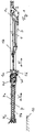
- FIG. 1 is a side view of a main boom 1 of a telescopic crane, not shown, shown.
- a base frame 2 of a superstructure is shown.
- On the base frame 2 of the main boom 1 is pivotally mounted with its main boom 1c in the usual manner about a substantially horizontal axis and a symbolically indicated by a line rocker cylinder 3, which engages the base frame and the main boom 1, in a corresponding manner set up and rocker ,
- the main boom 1 is shown in a so-called stowed position, in which the main boom 1 is aligned with its longitudinal direction substantially horizontally.
- the main boom 1 is designed as a telescopic boom with a base box 1 b and guided therein telescopic shots 1 d and has at its end remote from the base frame 2 of the superstructure end a main boom head 1 b and thus at the innermost telescopic section 1 d20.
- the telescopic boom can be extended and retracted in the usual way via a telescopic cylinder (not shown) arranged in the innermost telescopic section 1d.
- An extension of the main boom 1 in the form of a main boom extension 4 is detachably attached to the main boom head 1b.
- the main boom extension 4 can be used temporarily or permanently with the telescopic crane to achieve over the largest boom length of the main boom 1 beyond even greater overall length of the boom or to allow working behind building edges.
- This main boom extension 4 is designed as a lattice mast, which is a truss pipe construction in the usual way.
- the main boom 1 and the main boom extension 4 are located in the FIG. 1 in a 0 ° position or basic position in which the longitudinal direction H of the main boom 1 and the longitudinal direction V of the main boom extension 4 are aligned with one another or run parallel to one another.
- a so-called rocking angle a of the main boom 1 relative to the superstructure 2 is thus 0 ° in the stored position.
- the main boom extension 4 is spaced in this basic position of a bottom 10 and is thus supported by the main boom 1 via a bolt on the main boom head 1a.
- Such main boom extensions 4 are basically modular systems composed of individual main elements and can be assembled according to the requirements of its length or load capacity.
- the individual main elements have transportable dimensions and are not carried along with the telescopic crane in most cases, but are transported separately. If allow the axle loads of the telescopic crane and the size of the main boom extension 4, if necessary, the main boom extension 4 can be carried. This would then be in a transport position laterally next to and parallel to the main boom 1.
- the attachment to the main boom head 1a can be made elementary or as a preassembled unit or units.
- FIG. 2a shows a side view of an Abwinkellasche 9 in a fully extended 40 ° position.
- the sliding lug 9b is formed as an elongated flat profile with the stopper opening 9c and extends substantially parallel to the longitudinal direction V of the main boom extension 1.
- the sliding lug 9b has a bore 9j (see FIG Figure 2d ), via which the sliding tab 9b is detachably fastened in each case to a connecting bolt 9e on the main boom head 1a at one of the bolting points E and F.
- the connecting bolt 9e is aligned with its longitudinal extension parallel to the upper or lower roller head axles 12a, 12b.
- the guide plate 9d is pushed, which for this purpose has a closed rectangular cross-section with a guide opening 9f (see FIG. 2b ), in which the sliding tab 9b is inserted and slidably guided.
- the guide lug 9d per se is detachably fastened to the main boom extension 4 on one end facing the main jib head 1a via a respective further connecting bolt 9i in one of the bolting points G and H.
- the connecting pin 9i is aligned with its longitudinal extent parallel to the upper and lower roller head axles 12a, 12b.
- the terminal bolt 9i is through the stopper opening 9c of the sliding tab 9b passed.
- two stop holes 9g which are continuous and spaced apart in the longitudinal direction of the guide lug 9d, are provided (see FIG Figure 2d ) are arranged in the side parts of the guide tab 9d.
- a first of the two stop holes 9g serves to limit the angle of deflection b to 20 ° and a second to 40 °.
- the stop holes 9g for 40 ° are correspondingly closer to the main boom head 1a arranged to allow a larger displacement.
- a stop pin 9h is inserted into the respective stop hole, which then passes through the two opposite stop holes 9g and the intermediate stop opening 9c.
- the stopper pin 9h is inserted into the second of the two stopper holes 9g, which limits the angle of deflection b to 40 °.
- the stopper pin 9h is guided adjacent to the pin 9i in the stopper opening 9c.
- the bolt 9i would come into contact only with the opposing abutment surface 9a of the stopper opening 9c when no stopper bolt 9h is inserted.
- the second of the two stop holes 9g is free.
- FIG. 2b is a sectional view of FIG. 2a shown along the section line AA. It can be seen that the guide lug 9d has a rectangular cross-section with a central guide opening 9f, in which the sliding lug 9b is guided with its stop opening 9c.
- FIG. 2c a plan view of an Abwinkellasche 9 shown in a transport position.
- the Abwinkellasche 9 is not attached via the connecting bolt 9e on the main boom head 1a and the sliding tab 9b is inserted in the direction of the main boom extension 4 in the guide tab 9d.
- the connecting bolt 9e and the stopper pin 9h are inserted for storage.
- FIG. 2d shows a sectional view of Figure 2c along the section line BB in Figure 2c , In this view, the stop opening 12c and the two stop holes are clearly visible.
- FIG. 2e is a side view of an Abwinkellasche 9 shown in the Essentially the in FIG. 2a shown Abwinkellasche 9 corresponds. Unlike in the FIG. 2a the Abwinkellasche 9 is not shown in the 40 ° position, but in the 20 ° position. Correspondingly, the stopper bolt 9h is inserted in the stopper hole 9g remote from the main boom head 1a.
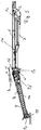
- FIG. 3 the main boom 1 after FIG. 1 with the main boom extension 4 in a 20 ° position, the previously described position is shown, in which the lowered tip 4a is supported on the floor 10.
- FIG. 4 shows the main boom 1 after FIG. 3 with the main boom extension 1a in a 40 ° position, in which the lowered tip 4a is supported on the floor 10.
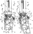
- FIG. 5 shows a detail view of FIG. 4 from the area of the coupling of the main boom extension 4 to the main boom 1 with a Abwinkellasche 9 in stop position to a desired maximum Abwinkel thoroughly.
- FIG. 6 a detail view from the field of coupling of the main boom extension 4 to the main boom 1 in the basic position.
- the kinetic energy for bending the main boom extension 4 is provided here as an alternative to the previously described embodiment via a combination of a coupling rod 11 with a telescoping cylinder telescopic main boom 1 available.
- the coupling rod 11 is aligned substantially parallel to the longitudinal direction H of the main boom 1 and to the longitudinal direction V of the main boom extension 4 and coupled to a first coupling rod end 11a in the region of the upper chord 4a of the main boom extension 4 via a horizontally extending pin.
- the opposite second coupling rod end 11 b is also mounted via a horizontally extending bolt on a base box 1 b of the main boom 1.
- the length of the coupling rod 11 is selected such that a telescopic weft 1c extended by an extension path x relative to the base box 1b is subsequently retractable and extendable in such a way that the main boom extension 4 can be lifted and lowered pivotally about the rocking axis W against the force of gravity of the main boom extension 4.
- the Coupling rod 11 are provided with a slot 11c to connect after extension of the main boom 1 to the extension x the coupling rod 11 easier with the main boom 1 and the main boom extension 4. A first slight lifting of the main boom extension 4 is required to relieve the upper bolt 6 and then remove.
- the telescopic section 1c is retracted and, viewed in relative terms, the length of the coupling rod 11 is released, which leads to angling of the main boom extension 4.
- the coupling rod 11 is removed.
- the main boom extension 4 further angled and the tip 4c of the main boom extension 4 slides through the floor 10 in the direction of the upper carriage 2.
- FIG. 7 is a view like in FIG. 6 shown in another position of the main boom extension 4. It can be seen that the main boom extension 4 is already bent so far that the tip 4 c has reached the bottom 10. The telescopic section 1c is retracted and the coupling rod 11 is relieved. When this position is reached, the next step is the removal of the coupling rod 11 and the further bending over the interaction of setting up the main boom 1 and the Abwinkellaschen. 9
- a backward angle of the main boom extension 4 takes place in the reverse order.
- main boom 1 may also be a lattice boom or a combination of telescopic boom, lattice boom and / or box boom.
- skin extension boom 4 lattice boom or box boom or combinations thereof are conceivable.
Landscapes
- Engineering & Computer Science (AREA)
- Mechanical Engineering (AREA)
- Jib Cranes (AREA)
Claims (6)
- Grue mobile comprenant une flèche principale (1) montée de manière basculante sur celle-ci et orientable par le biais d'un cylindre basculant (3) et une extension de flèche principale (4) reliée de manière amovible à une tête de flèche principale (1a) de la flèche principale (1) par le biais de boulons supérieurs (7) et de boulons inférieurs, l'extension de flèche principale (4) pouvant être pliée au moyen d'un entraînement de pliage sur un axe de basculement (W) par rapport à la flèche principale (1) depuis une position de base après desserrage des boulons supérieurs (7), l'entraînement de pliage s'engageant au niveau d'un pied (4d) de l'extension de flèche principale (4), un entraînement de la grue mobile destiné à une autre tâche fournissant l'énergie cinétique de l'entraînement de pliage, caractérisé en ce que l'entraînement de pliage est conçu de telle sorte que l'énergie cinétique destinée à l'entraînement soit fourni par l'escamotage et le déploiement de la flèche principale (1) au moyen d'un cylindre télescopique de la flèche principale (1).
- Grue mobile selon la revendication 1, caractérisée en ce que l'entraînement de pliage s'engage d'une part au niveau de la flèche principale (1) et d'autre part au niveau de l'extension de flèche principale (4) dans la région de sa membrure supérieure (4a).
- Grue mobile selon la revendication 1 ou 2, caractérisée en ce que l'entraînement de pliage est conçu de telle sorte que l'extension de flèche principale (4) puisse être levée et abaissée par pivotement sur l'axe de basculement (W) en s'opposant à la force de gravité de l'extension de flèche principale (4).
- Grue mobile selon l'une des revendications 1 à 3, caractérisée en ce que l'axe de basculement (W) est formé par un axe de tête de rouleau inférieur (12b).
- Grue mobile selon l'une des revendications 1 à 4, caractérisée en ce que l'entraînement de pliage comprend une tige d'accouplement (11), la tige d'accouplement (11) est fixée, à une première extrémité de tige d'accouplement (11a), à la membrure supérieure (4a) de l'extension de flèche principale (4) et, à une deuxième extrémité de tige d'accouplement (11b), à la flèche principale (1), la longueur de la tige d'accouplement (11) est choisie de telle sorte qu'une flèche principale (1), qui a été déployée au préalable d'une course de déploiement (x), puisse ensuite être escamotée et déployée de manière à ce que l'extension de flèche principale (4) puisse être levée et abaissée par pivotement sur l'axe de basculement (W) en s'opposant à la force de gravité de l'extension de flèche principale (4).
- Procédé de pliage d'une extension de flèche principale (4) par rapport à une flèche principale (1) d'une grue mobile, en particulier d'une grue mobile selon l'une des revendications 1 à 5, la flèche principale (1) étant montée de manière inclinable sur la grue mobile et pouvant être orientée au moyen d'un cylindre de basculement (3), l'extension de flèche principale (4) étant reliée de manière amovible à une tête de flèche principale (1a) de la flèche principale (1) par des boulons supérieurs (5) et des boulons inférieurs (6), un entraînement de pliage s'engageant au niveau d'un pied (4d) de l'extension de flèche principale (4), l'extension de flèche principale (4) étant soulevée depuis une position de base sur un axe de basculement (W) par rapport à la flèche principale (1) au moyen de l'entraînement de pliage qui tire pour le pliage son énergie cinétique d'un entraînement de la grue mobile qui est destiné par ailleurs à une autre tâche de la grue mobile, jusqu'à ce que les boulons supérieurs (5) soient dégagés et jusqu'à ce que les boulons supérieurs (5) soient ensuite retirés, caractérisé en ce que des attaches de pliage (9) sont insérées ou sont déjà insérées entre la tête de flèche principale (1a) et une membrure supérieure (4a) de l'extension de flèche principale (4), lesquelles attaches permettent de limiter le pliage souhaité de l'extension de flèche principale (4) par rapport à la flèche principale (1), en ce que l'extension de flèche principale (4) est abaissée au moyen de l'entraînement de pliage jusqu'à ce que la position de pliage maximale soit atteinte ou jusqu'à ce qu'un bout (4c) de l'extension de flèche principale (4) vienne en appui sur un sol (10), en ce que l'entraînement de la grue mobile est séparé de l'entraînement de pliage et, si la position de pliage maximale n'est pas encore atteinte, l'extension de flèche principale (4) est pliée par orientation de la flèche principale (1) jusqu'à atteindre le pliage souhaité et en ce qu'une tige d'accouplement (11) est reliée à la flèche principale (1) pour fournir l'énergie cinétique et à l'extension de flèche principale (4) et l'énergie cinétique est fournie par l'escamotage et le déploiement de la flèche principale (1).
Applications Claiming Priority (2)
| Application Number | Priority Date | Filing Date | Title |
|---|---|---|---|
| DE102015120350.2A DE102015120350B3 (de) | 2015-11-24 | 2015-11-24 | Mobilkran zum Abwinkeln einer Hauptauslegerverlängerung relativ zu einem Hauptausleger eines Mobilkrans |
| PCT/EP2016/078467 WO2017089356A1 (fr) | 2015-11-24 | 2016-11-22 | Grue mobile et procédé pour permettre un déplacement angulaire d'une rallonge de flèche principale par rapport à une flèche principale d'une grue mobile |
Publications (2)
| Publication Number | Publication Date |
|---|---|
| EP3337752A1 EP3337752A1 (fr) | 2018-06-27 |
| EP3337752B1 true EP3337752B1 (fr) | 2019-05-08 |
Family
ID=57354395
Family Applications (2)
| Application Number | Title | Priority Date | Filing Date |
|---|---|---|---|
| EP16798537.3A Active EP3347300B1 (fr) | 2015-11-24 | 2016-11-22 | Grue mobile permettant un déplacement angulaire d'une rallonge de flèche principale par rapport à une flèche principale d'une grue mobile |
| EP16798539.9A Active EP3337752B1 (fr) | 2015-11-24 | 2016-11-22 | Grue mobile et procédé pour permettre un déplacement angulaire d'une rallonge de flèche principale par rapport à une flèche principale d'une grue mobile |
Family Applications Before (1)
| Application Number | Title | Priority Date | Filing Date |
|---|---|---|---|
| EP16798537.3A Active EP3347300B1 (fr) | 2015-11-24 | 2016-11-22 | Grue mobile permettant un déplacement angulaire d'une rallonge de flèche principale par rapport à une flèche principale d'une grue mobile |
Country Status (5)
| Country | Link |
|---|---|
| US (2) | US10781083B2 (fr) |
| EP (2) | EP3347300B1 (fr) |
| CN (2) | CN108883916B (fr) |
| DE (1) | DE102015120350B3 (fr) |
| WO (2) | WO2017089356A1 (fr) |
Families Citing this family (15)
| Publication number | Priority date | Publication date | Assignee | Title |
|---|---|---|---|---|
| JP6531448B2 (ja) * | 2015-03-20 | 2019-06-19 | 株式会社タダノ | ジブ連結構造 |
| DE102015119381B3 (de) | 2015-11-10 | 2017-04-27 | Terex Global Gmbh | Mobilkran und Verfahren zum Abwinkeln einer Hauptauslegerverlängerung relativ zu einem Hauptausleger eines Mobilkrans |
| DE102015119379B3 (de) | 2015-11-10 | 2017-03-30 | Terex Global Gmbh | Mobilkran und Verfahren zum Abwinkeln einer Hauptauslegerverlängerung relativ zu einem Hauptausleger eines Mobilkrans |
| DE102015120350B3 (de) | 2015-11-24 | 2017-05-24 | Terex Global Gmbh | Mobilkran zum Abwinkeln einer Hauptauslegerverlängerung relativ zu einem Hauptausleger eines Mobilkrans |
| DE102016114837A1 (de) | 2016-08-10 | 2018-02-15 | Terex Global Gmbh | Teleskopausleger mit Abspannsystem für einen Mobilkran und Abspannverfahren hierfür |
| DE102017101113B3 (de) | 2017-01-20 | 2018-07-12 | Terex Global Gmbh | Teleskopausleger mit Stangenabspannsystem für einen Mobilkran und Abspannverfahren hierfür |
| DE102017110412B4 (de) * | 2017-05-12 | 2020-06-10 | Liebherr-Werk Ehingen Gmbh | Teleskopausleger und Mobilkran |
| DE102019104142B9 (de) * | 2019-02-19 | 2020-11-19 | Liebherr-Werk Ehingen Gmbh | Klappbare Schwebeballastführung für einen Kran |
| DE102019120134B3 (de) | 2019-07-25 | 2020-09-10 | Tadano Demag Gmbh | Fahrzeugkran und Fahrzeugkransystem sowie Verfahren zum Aufrüsten und Abrüsten eines Fahrzeugkrans mit einer Abspannvorrichtung |
| DE102020101101B3 (de) | 2020-01-17 | 2021-05-20 | Tadano Demag Gmbh | Auslegersystem für einen Fahrzeugkran mit Abspannvorrichtung sowie Verfahren zum Aufrüsten und Abrüsten einer Abspannvorrichtung eines Fahrzeugkrans |
| CN112141912B (zh) * | 2020-09-02 | 2022-01-07 | 中联重科股份有限公司 | 拉板组件、起重机吊臂以及起重机 |
| JP2022084003A (ja) | 2020-11-25 | 2022-06-06 | タダノ デマグ ゲーエムベーハー | 基本伸縮ジブおよび追加伸縮ジブを有する移動式クレーンの伸縮ジブシステム、および対応する方法 |
| JP2022167829A (ja) | 2021-04-23 | 2022-11-04 | タダノ デマグ ゲーエムベーハー | 固定およびロックユニットを有する伸縮ジブを有する車両クレーン |
| CN113753772B (zh) * | 2021-08-31 | 2023-06-20 | 湖南三一中型起重机械有限公司 | 一种插拔销机构及起重机 |
| CN114538293A (zh) * | 2022-02-28 | 2022-05-27 | 湖南三一塔式起重机械有限公司 | 塔式起重机 |
Family Cites Families (40)
| Publication number | Priority date | Publication date | Assignee | Title |
|---|---|---|---|---|
| DE291531C (fr) | ||||
| US3085695A (en) * | 1961-03-23 | 1963-04-16 | Carl A Miller | Hinge for crane boom |
| FR2075866A1 (fr) | 1969-12-31 | 1971-10-15 | Inst Foerdertechnik | |
| GB1470488A (en) | 1975-05-21 | 1977-04-14 | Hiab Foco Ab | Crane adapted to be mounted on a vehicle |
| FR2409225A1 (fr) * | 1977-11-21 | 1979-06-15 | Creusot Loire | Perfectionnement aux grues telescopiques |
| US4318488A (en) | 1980-07-28 | 1982-03-09 | Harnischfeger Corporation | Method of extending a jib of a telescopic crane |
| US4394941A (en) | 1981-08-31 | 1983-07-26 | Thomas L. Shannon, Jr. | Fluid dispenser |
| JPS60100390A (ja) * | 1983-11-04 | 1985-06-04 | 株式会社デンソー | セラミツク発熱体の支持構造 |
| JPS60100390U (ja) * | 1983-12-14 | 1985-07-09 | 株式会社 多田野鉄工所 | 補助ジブ付油圧伸縮式ブ−ムにおける補助ジブの可変チルト装置 |
| US4653655A (en) * | 1985-12-23 | 1987-03-31 | Harnischfeger Corporation | Crane boom having variable angle offset capability |
| JPS6327396A (ja) | 1986-07-21 | 1988-02-05 | 株式会社タダノ | 伸縮ブ−ムに継ぎ足されるジブ |
| DD291531A5 (de) * | 1990-01-08 | 1991-07-04 | Maschinenbau "Karl Marx",De | Ausleger mit einer vorrichtung fuer ein- oder mehrteilige abwippbare auslegerverlaengerungen fuer krane, insbesondere mobile krane |
| FR2719574B1 (fr) | 1994-05-06 | 1996-07-26 | Ppm | Ensemble de prolongation pour flèche télescopique de grue mobile et grue mobile en faisant application. |
| FR2732000B1 (fr) * | 1995-03-22 | 1997-05-30 | Potain Sa | Grue a montage automatise avec fleche repliable sur elle-meme |
| JPH09104588A (ja) * | 1995-10-06 | 1997-04-22 | Komatsu Ltd | クレーンの補助ジブ張出、格納装置 |
| DE69727719T2 (de) * | 1996-03-04 | 2005-01-13 | Manitowoc Crane Companies, Inc., Reno | Aushängbare Verbindung zum Falten eines Wippauslegers |
| CN2364010Y (zh) | 1999-03-26 | 2000-02-16 | 郑州铁路局工务机械厂 | 一种液压折臂起重机 |
| BE1012862A5 (nl) | 1999-08-31 | 2001-04-03 | Lille Allebroer Leo Alix De | Inrichting voor het verplaatsen van lasten met behulp van een mobiel platform. |
| DE10321493B4 (de) * | 2003-05-13 | 2006-07-20 | Grove U.S. Llc | Klappspitzen-Abwinklungsvorrichtung |
| WO2005021415A1 (fr) * | 2003-08-22 | 2005-03-10 | Terex-Demag Gmbh & Co. Kg | Fleche de grue mobile comportant une unite hydraulique autonome montee sur cette derniere |
| US7546928B2 (en) * | 2006-10-27 | 2009-06-16 | Manitowoc Crane Companies, Inc. | Mobile lift crane with variable position counterweight |
| US20100252522A1 (en) * | 2007-04-19 | 2010-10-07 | Terex Demag Gmbh | Auxiliary Device For Installing The Lower And Upper Jib Support Of An Adjustable Auxiliary Boom On A Mobile Crane |
| DE202007012204U1 (de) * | 2007-08-29 | 2007-10-31 | Terex-Demag Gmbh & Co. Kg | Element zum Verbinden eines Gittersystems |
| CN101628691A (zh) | 2008-07-18 | 2010-01-20 | 卫华集团有限公司 | 一种起重机俯仰缠绕机构 |
| DE102009007776A1 (de) | 2009-02-04 | 2010-08-12 | Terex Demag Gmbh | Steuerung für eine verstellbare Auslegerverlängerung eines Mobilkrans |
| DE102009010452A1 (de) * | 2009-02-26 | 2010-09-02 | Terex-Demag Gmbh | Verfahren und Einrichtung zum An-und Abbau einer Zusatzeinrichtung am Hauptausleger eines Mobilkrans |
| DE102009022262A1 (de) | 2009-05-22 | 2010-11-25 | Terex Demag Gmbh | Winkelverstellung eines Auslegersystems |
| CN201458603U (zh) | 2009-08-12 | 2010-05-12 | 中国船舶重工集团公司第七一三研究所 | 起重臂折叠机构 |
| DE102009053235A1 (de) | 2009-11-06 | 2011-05-19 | Gottwald Port Technology Gmbh | Umschlagsystem für ISO-Container mit einer Containerbrücke |
| DE102010007545A1 (de) | 2010-02-11 | 2011-08-11 | Gottwald Port Technology GmbH, 40597 | Kran, insbesondere Hafenmobilkran, mit einem Hybridantriebssystem |
| DE102011053014A1 (de) | 2011-08-26 | 2013-02-28 | Demag Cranes & Components Gmbh | Steuerungsanordnung zum parallelen Betreiben von mindestens zwei Hebezeugen, insbesondere Kranen |
| CN102602825B (zh) * | 2012-03-13 | 2014-07-16 | 中联重科股份有限公司 | 副臂展收装置、臂架结构和起重机 |
| CN103359636A (zh) * | 2012-03-28 | 2013-10-23 | 江苏华澄重工有限公司 | 单臂架门座起重机臂架重心补偿装置 |
| DE102012023814B4 (de) | 2012-12-05 | 2015-02-05 | Liebherr-Werk Ehingen Gmbh | Klappspitze für einen Mobilkran und Verfahren zum Verschwenken der Klappspitze |
| DE102014102121A1 (de) | 2014-02-19 | 2015-08-20 | Terex Mhps Gmbh | Hafenkran |
| DE102014003831A1 (de) | 2014-03-18 | 2015-09-24 | Liebherr-Werk Ehingen Gmbh | Kranauslegersystem mit einem ersten Auslegerelement und einem daran wippbar angelenkten zweiten Auslegerelement sowie Kran |
| DE102015202734A1 (de) | 2015-02-16 | 2016-08-18 | Terex Cranes Germany Gmbh | Kran und Verfahren zum Beeinflussen einer Verformung eines Auslegersystems eines derartigen Krans |
| DE102015119379B3 (de) | 2015-11-10 | 2017-03-30 | Terex Global Gmbh | Mobilkran und Verfahren zum Abwinkeln einer Hauptauslegerverlängerung relativ zu einem Hauptausleger eines Mobilkrans |
| DE102015119381B3 (de) | 2015-11-10 | 2017-04-27 | Terex Global Gmbh | Mobilkran und Verfahren zum Abwinkeln einer Hauptauslegerverlängerung relativ zu einem Hauptausleger eines Mobilkrans |
| DE102015120350B3 (de) | 2015-11-24 | 2017-05-24 | Terex Global Gmbh | Mobilkran zum Abwinkeln einer Hauptauslegerverlängerung relativ zu einem Hauptausleger eines Mobilkrans |
-
2015
- 2015-11-24 DE DE102015120350.2A patent/DE102015120350B3/de not_active Expired - Fee Related
-
2016
- 2016-11-22 WO PCT/EP2016/078467 patent/WO2017089356A1/fr not_active Ceased
- 2016-11-22 CN CN201680068448.4A patent/CN108883916B/zh not_active Expired - Fee Related
- 2016-11-22 EP EP16798537.3A patent/EP3347300B1/fr active Active
- 2016-11-22 US US15/778,124 patent/US10781083B2/en active Active
- 2016-11-22 WO PCT/EP2016/078461 patent/WO2017089353A1/fr not_active Ceased
- 2016-11-22 CN CN201680068460.5A patent/CN108290724B/zh active Active
- 2016-11-22 EP EP16798539.9A patent/EP3337752B1/fr active Active
- 2016-11-22 US US15/778,432 patent/US10640340B2/en active Active
Non-Patent Citations (1)
| Title |
|---|
| None * |
Also Published As
| Publication number | Publication date |
|---|---|
| DE102015120350B3 (de) | 2017-05-24 |
| EP3347300A1 (fr) | 2018-07-18 |
| WO2017089356A1 (fr) | 2017-06-01 |
| US20180346292A1 (en) | 2018-12-06 |
| CN108290724B (zh) | 2019-09-27 |
| CN108290724A (zh) | 2018-07-17 |
| WO2017089353A1 (fr) | 2017-06-01 |
| US10640340B2 (en) | 2020-05-05 |
| CN108883916B (zh) | 2020-01-03 |
| EP3337752A1 (fr) | 2018-06-27 |
| EP3347300B1 (fr) | 2019-05-08 |
| CN108883916A (zh) | 2018-11-23 |
| US20180339889A1 (en) | 2018-11-29 |
| US10781083B2 (en) | 2020-09-22 |
Similar Documents
| Publication | Publication Date | Title |
|---|---|---|
| EP3347300B1 (fr) | Grue mobile permettant un déplacement angulaire d'une rallonge de flèche principale par rapport à une flèche principale d'une grue mobile | |
| DE102015119381B3 (de) | Mobilkran und Verfahren zum Abwinkeln einer Hauptauslegerverlängerung relativ zu einem Hauptausleger eines Mobilkrans | |
| DE102015119379B3 (de) | Mobilkran und Verfahren zum Abwinkeln einer Hauptauslegerverlängerung relativ zu einem Hauptausleger eines Mobilkrans | |
| EP2465809B1 (fr) | Système de télescopage pour flèche et flèche auxiliaire | |
| EP2218836A1 (fr) | Véhicule, notamment véhicule de chantier | |
| DE102017117958B4 (de) | Kran und Gegengewicht für einen Kran | |
| DE102007058553A1 (de) | Seitliche Abspannung für einen Gitterausleger eines Kranes | |
| DE202008006457U1 (de) | Auslegerelement für ein Hebezeug | |
| DE102014012661A1 (de) | Verfahren zum Betrieb eines Krans und Kran | |
| WO2009118198A2 (fr) | Dispositif pour démolir des constructions | |
| DE102013011180B4 (de) | Kragenlagerung für einen Teleskopausleger sowie Teleskopausleger und Kran | |
| DE102013011173B4 (de) | Verfahren zur Montage eines Krans sowie Anlenkschuss, Teleskopausleger und Kran | |
| DE102015001619B4 (de) | Auslegersystem für einen Mobilkran sowie Mobilkran | |
| DE102013006259B4 (de) | Teleskopausleger und Kran | |
| DE102017000389B4 (de) | Kranausleger, Kran mit einem solchen Kranausleger und Verfahren zum Anbringen einer Abspannstütze an einem solchen Kranausleger | |
| DE102021130736B4 (de) | Teleskopauslegersystem eines Mobilkrans mit einem Grundteleskopausleger und einem Zusatzteleskopausleger und Verfahren hierzu | |
| DE69810981T2 (de) | Technik zum Aufrichten des Mastes für einen Teleskopkran | |
| DE202008009281U1 (de) | Kran | |
| DE102020131617B4 (de) | Mobilkran umfassend einen Oberwagen mit wenigstens einer Lagerstelle zum Anbolzen eines Auslegers | |
| EP4083346B1 (fr) | Dispositif de support pour une pompe à béton sur camion | |
| DE102022128653B4 (de) | Fahrbarer Kran mit Gittermastausleger, Gittermastausleger sowie Verfahren zur Montage eines solchen | |
| EP1541520A1 (fr) | Grue mobile | |
| DE202017000243U1 (de) | Auslegerverstellvorrichtung für ein Arbeitsgerät | |
| DE10226319B4 (de) | Fahrzeugkran mit ein- und ausfahrbarer Koppeleinrichtung für ein Gegengewicht | |
| DE102024115384A1 (de) | System und Bolzenzieheinrichtung zum manuellen Stecken / Ziehen von Bolzen |
Legal Events
| Date | Code | Title | Description |
|---|---|---|---|
| STAA | Information on the status of an ep patent application or granted ep patent |
Free format text: STATUS: UNKNOWN |
|
| STAA | Information on the status of an ep patent application or granted ep patent |
Free format text: STATUS: THE INTERNATIONAL PUBLICATION HAS BEEN MADE |
|
| PUAI | Public reference made under article 153(3) epc to a published international application that has entered the european phase |
Free format text: ORIGINAL CODE: 0009012 |
|
| STAA | Information on the status of an ep patent application or granted ep patent |
Free format text: STATUS: REQUEST FOR EXAMINATION WAS MADE |
|
| 17P | Request for examination filed |
Effective date: 20180321 |
|
| AK | Designated contracting states |
Kind code of ref document: A1 Designated state(s): AL AT BE BG CH CY CZ DE DK EE ES FI FR GB GR HR HU IE IS IT LI LT LU LV MC MK MT NL NO PL PT RO RS SE SI SK SM TR |
|
| AX | Request for extension of the european patent |
Extension state: BA ME |
|
| GRAP | Despatch of communication of intention to grant a patent |
Free format text: ORIGINAL CODE: EPIDOSNIGR1 |
|
| STAA | Information on the status of an ep patent application or granted ep patent |
Free format text: STATUS: GRANT OF PATENT IS INTENDED |
|
| DAV | Request for validation of the european patent (deleted) | ||
| DAX | Request for extension of the european patent (deleted) | ||
| RIC1 | Information provided on ipc code assigned before grant |
Ipc: B66C 23/68 20060101AFI20190205BHEP Ipc: B66C 23/70 20060101ALI20190205BHEP Ipc: B66C 23/42 20060101ALI20190205BHEP |
|
| INTG | Intention to grant announced |
Effective date: 20190222 |
|
| RAP1 | Party data changed (applicant data changed or rights of an application transferred) |
Owner name: TEREX GLOBAL GMBH |
|
| GRAS | Grant fee paid |
Free format text: ORIGINAL CODE: EPIDOSNIGR3 |
|
| GRAA | (expected) grant |
Free format text: ORIGINAL CODE: 0009210 |
|
| STAA | Information on the status of an ep patent application or granted ep patent |
Free format text: STATUS: THE PATENT HAS BEEN GRANTED |
|
| AK | Designated contracting states |
Kind code of ref document: B1 Designated state(s): AL AT BE BG CH CY CZ DE DK EE ES FI FR GB GR HR HU IE IS IT LI LT LU LV MC MK MT NL NO PL PT RO RS SE SI SK SM TR |
|
| REG | Reference to a national code |
Ref country code: GB Ref legal event code: FG4D Free format text: NOT ENGLISH |
|
| REG | Reference to a national code |
Ref country code: CH Ref legal event code: EP Ref country code: AT Ref legal event code: REF Ref document number: 1129825 Country of ref document: AT Kind code of ref document: T Effective date: 20190515 |
|
| REG | Reference to a national code |
Ref country code: IE Ref legal event code: FG4D Free format text: LANGUAGE OF EP DOCUMENT: GERMAN |
|
| REG | Reference to a national code |
Ref country code: DE Ref legal event code: R096 Ref document number: 502016004644 Country of ref document: DE |
|
| REG | Reference to a national code |
Ref country code: NL Ref legal event code: MP Effective date: 20190508 |
|
| REG | Reference to a national code |
Ref country code: LT Ref legal event code: MG4D |
|
| PG25 | Lapsed in a contracting state [announced via postgrant information from national office to epo] |
Ref country code: NO Free format text: LAPSE BECAUSE OF FAILURE TO SUBMIT A TRANSLATION OF THE DESCRIPTION OR TO PAY THE FEE WITHIN THE PRESCRIBED TIME-LIMIT Effective date: 20190808 Ref country code: ES Free format text: LAPSE BECAUSE OF FAILURE TO SUBMIT A TRANSLATION OF THE DESCRIPTION OR TO PAY THE FEE WITHIN THE PRESCRIBED TIME-LIMIT Effective date: 20190508 Ref country code: LT Free format text: LAPSE BECAUSE OF FAILURE TO SUBMIT A TRANSLATION OF THE DESCRIPTION OR TO PAY THE FEE WITHIN THE PRESCRIBED TIME-LIMIT Effective date: 20190508 Ref country code: HR Free format text: LAPSE BECAUSE OF FAILURE TO SUBMIT A TRANSLATION OF THE DESCRIPTION OR TO PAY THE FEE WITHIN THE PRESCRIBED TIME-LIMIT Effective date: 20190508 Ref country code: NL Free format text: LAPSE BECAUSE OF FAILURE TO SUBMIT A TRANSLATION OF THE DESCRIPTION OR TO PAY THE FEE WITHIN THE PRESCRIBED TIME-LIMIT Effective date: 20190508 Ref country code: PT Free format text: LAPSE BECAUSE OF FAILURE TO SUBMIT A TRANSLATION OF THE DESCRIPTION OR TO PAY THE FEE WITHIN THE PRESCRIBED TIME-LIMIT Effective date: 20190908 Ref country code: SE Free format text: LAPSE BECAUSE OF FAILURE TO SUBMIT A TRANSLATION OF THE DESCRIPTION OR TO PAY THE FEE WITHIN THE PRESCRIBED TIME-LIMIT Effective date: 20190508 Ref country code: AL Free format text: LAPSE BECAUSE OF FAILURE TO SUBMIT A TRANSLATION OF THE DESCRIPTION OR TO PAY THE FEE WITHIN THE PRESCRIBED TIME-LIMIT Effective date: 20190508 Ref country code: FI Free format text: LAPSE BECAUSE OF FAILURE TO SUBMIT A TRANSLATION OF THE DESCRIPTION OR TO PAY THE FEE WITHIN THE PRESCRIBED TIME-LIMIT Effective date: 20190508 |
|
| PG25 | Lapsed in a contracting state [announced via postgrant information from national office to epo] |
Ref country code: RS Free format text: LAPSE BECAUSE OF FAILURE TO SUBMIT A TRANSLATION OF THE DESCRIPTION OR TO PAY THE FEE WITHIN THE PRESCRIBED TIME-LIMIT Effective date: 20190508 Ref country code: LV Free format text: LAPSE BECAUSE OF FAILURE TO SUBMIT A TRANSLATION OF THE DESCRIPTION OR TO PAY THE FEE WITHIN THE PRESCRIBED TIME-LIMIT Effective date: 20190508 Ref country code: GR Free format text: LAPSE BECAUSE OF FAILURE TO SUBMIT A TRANSLATION OF THE DESCRIPTION OR TO PAY THE FEE WITHIN THE PRESCRIBED TIME-LIMIT Effective date: 20190809 Ref country code: BG Free format text: LAPSE BECAUSE OF FAILURE TO SUBMIT A TRANSLATION OF THE DESCRIPTION OR TO PAY THE FEE WITHIN THE PRESCRIBED TIME-LIMIT Effective date: 20190808 |
|
| PG25 | Lapsed in a contracting state [announced via postgrant information from national office to epo] |
Ref country code: CZ Free format text: LAPSE BECAUSE OF FAILURE TO SUBMIT A TRANSLATION OF THE DESCRIPTION OR TO PAY THE FEE WITHIN THE PRESCRIBED TIME-LIMIT Effective date: 20190508 Ref country code: SK Free format text: LAPSE BECAUSE OF FAILURE TO SUBMIT A TRANSLATION OF THE DESCRIPTION OR TO PAY THE FEE WITHIN THE PRESCRIBED TIME-LIMIT Effective date: 20190508 Ref country code: EE Free format text: LAPSE BECAUSE OF FAILURE TO SUBMIT A TRANSLATION OF THE DESCRIPTION OR TO PAY THE FEE WITHIN THE PRESCRIBED TIME-LIMIT Effective date: 20190508 Ref country code: DK Free format text: LAPSE BECAUSE OF FAILURE TO SUBMIT A TRANSLATION OF THE DESCRIPTION OR TO PAY THE FEE WITHIN THE PRESCRIBED TIME-LIMIT Effective date: 20190508 Ref country code: RO Free format text: LAPSE BECAUSE OF FAILURE TO SUBMIT A TRANSLATION OF THE DESCRIPTION OR TO PAY THE FEE WITHIN THE PRESCRIBED TIME-LIMIT Effective date: 20190508 |
|
| REG | Reference to a national code |
Ref country code: DE Ref legal event code: R097 Ref document number: 502016004644 Country of ref document: DE |
|
| PG25 | Lapsed in a contracting state [announced via postgrant information from national office to epo] |
Ref country code: SM Free format text: LAPSE BECAUSE OF FAILURE TO SUBMIT A TRANSLATION OF THE DESCRIPTION OR TO PAY THE FEE WITHIN THE PRESCRIBED TIME-LIMIT Effective date: 20190508 Ref country code: IT Free format text: LAPSE BECAUSE OF FAILURE TO SUBMIT A TRANSLATION OF THE DESCRIPTION OR TO PAY THE FEE WITHIN THE PRESCRIBED TIME-LIMIT Effective date: 20190508 |
|
| PGFP | Annual fee paid to national office [announced via postgrant information from national office to epo] |
Ref country code: FR Payment date: 20191219 Year of fee payment: 5 |
|
| PLBE | No opposition filed within time limit |
Free format text: ORIGINAL CODE: 0009261 |
|
| STAA | Information on the status of an ep patent application or granted ep patent |
Free format text: STATUS: NO OPPOSITION FILED WITHIN TIME LIMIT |
|
| PG25 | Lapsed in a contracting state [announced via postgrant information from national office to epo] |
Ref country code: TR Free format text: LAPSE BECAUSE OF FAILURE TO SUBMIT A TRANSLATION OF THE DESCRIPTION OR TO PAY THE FEE WITHIN THE PRESCRIBED TIME-LIMIT Effective date: 20190508 |
|
| 26N | No opposition filed |
Effective date: 20200211 |
|
| PG25 | Lapsed in a contracting state [announced via postgrant information from national office to epo] |
Ref country code: PL Free format text: LAPSE BECAUSE OF FAILURE TO SUBMIT A TRANSLATION OF THE DESCRIPTION OR TO PAY THE FEE WITHIN THE PRESCRIBED TIME-LIMIT Effective date: 20190508 |
|
| PG25 | Lapsed in a contracting state [announced via postgrant information from national office to epo] |
Ref country code: SI Free format text: LAPSE BECAUSE OF FAILURE TO SUBMIT A TRANSLATION OF THE DESCRIPTION OR TO PAY THE FEE WITHIN THE PRESCRIBED TIME-LIMIT Effective date: 20190508 |
|
| PG25 | Lapsed in a contracting state [announced via postgrant information from national office to epo] |
Ref country code: MC Free format text: LAPSE BECAUSE OF FAILURE TO SUBMIT A TRANSLATION OF THE DESCRIPTION OR TO PAY THE FEE WITHIN THE PRESCRIBED TIME-LIMIT Effective date: 20190508 Ref country code: LU Free format text: LAPSE BECAUSE OF NON-PAYMENT OF DUE FEES Effective date: 20191122 |
|
| REG | Reference to a national code |
Ref country code: BE Ref legal event code: MM Effective date: 20191130 |
|
| PG25 | Lapsed in a contracting state [announced via postgrant information from national office to epo] |
Ref country code: IE Free format text: LAPSE BECAUSE OF NON-PAYMENT OF DUE FEES Effective date: 20191122 |
|
| PG25 | Lapsed in a contracting state [announced via postgrant information from national office to epo] |
Ref country code: BE Free format text: LAPSE BECAUSE OF NON-PAYMENT OF DUE FEES Effective date: 20191130 |
|
| PGFP | Annual fee paid to national office [announced via postgrant information from national office to epo] |
Ref country code: CH Payment date: 20201118 Year of fee payment: 5 |
|
| PG25 | Lapsed in a contracting state [announced via postgrant information from national office to epo] |
Ref country code: CY Free format text: LAPSE BECAUSE OF FAILURE TO SUBMIT A TRANSLATION OF THE DESCRIPTION OR TO PAY THE FEE WITHIN THE PRESCRIBED TIME-LIMIT Effective date: 20190508 |
|
| PG25 | Lapsed in a contracting state [announced via postgrant information from national office to epo] |
Ref country code: IS Free format text: LAPSE BECAUSE OF FAILURE TO SUBMIT A TRANSLATION OF THE DESCRIPTION OR TO PAY THE FEE WITHIN THE PRESCRIBED TIME-LIMIT Effective date: 20190908 |
|
| GBPC | Gb: european patent ceased through non-payment of renewal fee |
Effective date: 20201122 |
|
| PG25 | Lapsed in a contracting state [announced via postgrant information from national office to epo] |
Ref country code: HU Free format text: LAPSE BECAUSE OF FAILURE TO SUBMIT A TRANSLATION OF THE DESCRIPTION OR TO PAY THE FEE WITHIN THE PRESCRIBED TIME-LIMIT; INVALID AB INITIO Effective date: 20161122 Ref country code: MT Free format text: LAPSE BECAUSE OF FAILURE TO SUBMIT A TRANSLATION OF THE DESCRIPTION OR TO PAY THE FEE WITHIN THE PRESCRIBED TIME-LIMIT Effective date: 20190508 |
|
| PG25 | Lapsed in a contracting state [announced via postgrant information from national office to epo] |
Ref country code: GB Free format text: LAPSE BECAUSE OF NON-PAYMENT OF DUE FEES Effective date: 20201122 |
|
| PG25 | Lapsed in a contracting state [announced via postgrant information from national office to epo] |
Ref country code: MK Free format text: LAPSE BECAUSE OF FAILURE TO SUBMIT A TRANSLATION OF THE DESCRIPTION OR TO PAY THE FEE WITHIN THE PRESCRIBED TIME-LIMIT Effective date: 20190508 |
|
| REG | Reference to a national code |
Ref country code: CH Ref legal event code: PL |
|
| PG25 | Lapsed in a contracting state [announced via postgrant information from national office to epo] |
Ref country code: FR Free format text: LAPSE BECAUSE OF NON-PAYMENT OF DUE FEES Effective date: 20211130 |
|
| REG | Reference to a national code |
Ref country code: AT Ref legal event code: MM01 Ref document number: 1129825 Country of ref document: AT Kind code of ref document: T Effective date: 20211122 |
|
| PG25 | Lapsed in a contracting state [announced via postgrant information from national office to epo] |
Ref country code: AT Free format text: LAPSE BECAUSE OF NON-PAYMENT OF DUE FEES Effective date: 20211122 |
|
| P01 | Opt-out of the competence of the unified patent court (upc) registered |
Effective date: 20230530 |
|
| PG25 | Lapsed in a contracting state [announced via postgrant information from national office to epo] |
Ref country code: LI Free format text: LAPSE BECAUSE OF NON-PAYMENT OF DUE FEES Effective date: 20220630 Ref country code: CH Free format text: LAPSE BECAUSE OF NON-PAYMENT OF DUE FEES Effective date: 20220630 |
|
| PGFP | Annual fee paid to national office [announced via postgrant information from national office to epo] |
Ref country code: DE Payment date: 20251119 Year of fee payment: 10 |