EP3338558B1 - Mahlvorrichtung zum feinmahlen von körnerfrüchten, insbesondere kaffeebohnen - Google Patents
Mahlvorrichtung zum feinmahlen von körnerfrüchten, insbesondere kaffeebohnen Download PDFInfo
- Publication number
- EP3338558B1 EP3338558B1 EP17205641.8A EP17205641A EP3338558B1 EP 3338558 B1 EP3338558 B1 EP 3338558B1 EP 17205641 A EP17205641 A EP 17205641A EP 3338558 B1 EP3338558 B1 EP 3338558B1
- Authority
- EP
- European Patent Office
- Prior art keywords
- milling
- grinding
- rollers
- grinder
- roller
- Prior art date
- Legal status (The legal status is an assumption and is not a legal conclusion. Google has not performed a legal analysis and makes no representation as to the accuracy of the status listed.)
- Active
Links
Images

Classifications
-
- A—HUMAN NECESSITIES
- A23—FOODS OR FOODSTUFFS; TREATMENT THEREOF, NOT COVERED BY OTHER CLASSES
- A23F—COFFEE; TEA; THEIR SUBSTITUTES; MANUFACTURE, PREPARATION, OR INFUSION THEREOF
- A23F5/00—Coffee; Coffee substitutes; Preparations thereof
- A23F5/08—Methods of grinding coffee
-
- A—HUMAN NECESSITIES
- A47—FURNITURE; DOMESTIC ARTICLES OR APPLIANCES; COFFEE MILLS; SPICE MILLS; SUCTION CLEANERS IN GENERAL
- A47J—KITCHEN EQUIPMENT; COFFEE MILLS; SPICE MILLS; APPARATUS FOR MAKING BEVERAGES
- A47J42/00—Coffee mills; Spice mills
- A47J42/32—Coffee mills; Spice mills with other grinding or pulverising members
- A47J42/36—Coffee mills; Spice mills with other grinding or pulverising members mechanically driven
-
- B—PERFORMING OPERATIONS; TRANSPORTING
- B02—CRUSHING, PULVERISING, OR DISINTEGRATING; PREPARATORY TREATMENT OF GRAIN FOR MILLING
- B02C—CRUSHING, PULVERISING, OR DISINTEGRATING IN GENERAL; MILLING GRAIN
- B02C4/00—Crushing or disintegrating by roller mills
- B02C4/02—Crushing or disintegrating by roller mills with two or more rollers
- B02C4/06—Crushing or disintegrating by roller mills with two or more rollers specially adapted for milling grain
Definitions
- the invention relates to a grinding device for the fine grinding of cereals, in particular coffee beans, with a housing in which a grinder, which can be driven by at least one drive device, is arranged, the grinder having a plurality of grinding rollers, which define at least two grinding passages, each with a grinding gap, such that a grinding gap is formed by the smallest distance d between two adjacent grinding rollers, all successive grinding passages being part of a product guide channel, at least a number n> 2 grinding rollers being provided which are arranged offset from one another in such a way that one grinding roller with two adjacent ones Grinding rollers each form a grinding gap d 1- (n-1) , so that the grinder has a number (n-1) of grinding passages.
- Generic grinding devices are for example from the US 1,530,615 A , of the US 3,167,261 A , of the EP 0 405 636 A1 , EP 0 115 440 A2 , of the DE 10 2008 054 255 A1 and the GB 198 120 A known. Although this reduces the installation space, it is difficult, because of the differently oriented grinding passages, to guide the ground material completely from an inlet opening to an outlet opening of the housing.
- the object of the invention is therefore to provide a grinding device for the fine grinding of cereals, which avoids the disadvantages mentioned above in a simple and inexpensive manner.
- the housing part has a continuous product guide channel from an inlet opening to an outlet opening and cutouts for the grinding rollers.
- Two grinding rollers can be arranged vertically one above the other, while the third grinding roller is arranged next to the first two grinding rollers. In this way, a very compact grinder is provided, and a grinding roller can also be saved compared to conventional grinders.
- a product guide channel is also created through which the ground cereals are optimally guided to the outlet opening without remaining in the housing.
- At least one grinding roller is adjustably supported by an adjusting device, that a diameter distance D 1-n can be changed from grinding rolls arranged adjacent to this adjustable grinding roller and thus at least one grinding gap d 1- (n-1) can be changed.
- the degree of grinding can be adjusted in a particularly simple manner.
- at least one grinding roller which forms two grinding gaps d with adjacent grinding rollers, is adjustably mounted.
- successive grinder rollers each have an opposite direction of rotation in the grinder, as seen in the direction of gravity.
- the drive device is operatively connected to a gear, by means of which the individual grinding rollers can be driven.
- a drive device can also be provided for each grinding roller. The speed of each grinding roller can then be adjusted individually, for example by means of a frequency converter.
- FIG. 1 shows a perspective view of a grinding device according to the invention for the fine grinding of cereals.
- the grinding device is used for the fine grinding of coffee beans.
- the grinding device 2 has a housing 4 which has further housing parts.
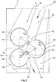
- a grinder 8 is provided, which in the present exemplary embodiment has three grinding rollers 10, 12, 14, which have two grinding passages 16, 18, each having a grinding gap d 1 and d 2 .
- the grinding rollers 10, 12, 14 can be corrugated or smooth.
- the grinding passages 16 and 18 are part of a product guide channel 20 which, viewed in the direction of gravity, leads from an inlet opening 22 to an outlet opening 24.
- all grinding rollers 10, 12 and 14 are each driven by a drive motor 26, only the drive motors 26 for the grinding rollers 10 and 12 being shown in the illustration.
- the grinding rollers 10 and 14 are arranged vertically one above the other.
- the grinding roller 12 is adjustably mounted so that a diameter distance D 1 , D 2 from the grinding rollers 10, 14 arranged adjacent to this adjustable grinding roller 12 can be varied.
- the adjustment takes place here via an adjustment device 28, which has an adjustment motor 30, which drives an adjustment spindle 32, which in turn meshes with an eccentric 34, which is connected in a rotationally fixed manner to the grinding roller 12.
- the grinding rollers 10, 12, 14 have a direction of rotation directed to the respective grinding passage 16, 18, what about this leads that the respective grinding rollers 10, 12 and 14, which each form a grinding gap d 1 , d 2 , have an opposite direction of rotation.
- a further improvement in fine grinding is achieved in that the rotational speeds w 1 , w 2 and w 3 of the grinding rollers 10, 12, 14 increase as seen in the direction of gravity.
- the housing part 6 of the grinder 8 is shown essentially in a schematic view.
- the housing part 6 here has a sheet metal insert 36 with sheet metal parts 38, 40, which forms the product guide channel 20 and has cutouts 42, 44, 46 for the grinding rollers 10, 12, 14.
- the sheet metal part 40 can be adjusted together with the grinding roller 12.
- the recess 44 is simply made larger in order to enable the grinding roller 12 to be adjusted.
- a product can be fed in via the inlet opening 22, for example using a vibration ring or a roller metering device.
- the ground coffee is driven by the grinding rollers 10, 12, 14 and gravity in the direction of the outlet opening 24 and from there it arrives in a grinding area collecting area 48 and has a grain size of ⁇ 500 ⁇ m.
- each grinding roller 10, 12, 14 is driven by a drive motor 26 in the present exemplary embodiment. It is of course also possible to provide only one drive motor, which drives the respective grinding rollers 10, 12, 14 via a gear.
Landscapes
- Engineering & Computer Science (AREA)
- Food Science & Technology (AREA)
- Mechanical Engineering (AREA)
- Life Sciences & Earth Sciences (AREA)
- Chemical & Material Sciences (AREA)
- Polymers & Plastics (AREA)
- Crushing And Grinding (AREA)
- Adjustment And Processing Of Grains (AREA)
Description
- Die Erfindung betrifft eine Mahlvorrichtung zum Feinmahlen von Körnerfrüchten, insbesondere Kaffeebohnen, mit einem Gehäuse, in dem ein Mahlwerk, das von mindestens einer Antriebsvorrichtung antreibbar ist, angeordnet ist, wobei das Mahlwerk mehrere Mahlwalzen aufweist, die mindestens zwei Mahlpassagen mit jeweils einem Mahlspalt definieren, derart, dass ein Mahlspalt durch einen geringsten Abstand d zweier benachbarter Mahlwalzen gebildet ist, wobei alle aufeinanderfolgenden Mahlpassagen Teil eines Produktführungskanals sind, wobei mindestens eine Anzahl n>2 Mahlwalzen vorgesehen sind, die derart versetzt zueinander angeordnet sind, dass eine Mahlwalze mit zwei benachbart angeordneten Mahlwalzen jeweils einen Mahlspalt d1-(n-1) ausbildet, so dass das Mahlwerk eine Anzahl (n-1) Mahlpassagen aufweist.
- Derartige Mahlwerke sind aus dem Stand der Technik hinlänglich bekannt. So offenbart die europäische Patentanmeldung
EP 2 412 246 A1 eine Mahlvorrichtung mit zwei Walzenpaaren und dementsprechend zwei Mahlpassagen für die industrielle Vermahlung von Kaffeebohnen. Auch die deutsche PatentschriftDE 42 34 991 C2 zeigt eine derartige Mahlvorrichtung zum Feinmahlen von Kaffeebohnen. Es sollte deutlich sein, dass die Anzahl Mahlpassagen den Feinmahlgrad wesentlich beeinflusst. Die Anzahl Mahlpassagen ist jedoch bei der gattungsgemäßen Mahlvorrichtung abhängig von den vorgesehenen Mahlwalzenpaaren. Aufgrund des großen benötigten Bauraums ist eine derartige Mahlvorrichtung auch lediglich für industrielle Anlagen geeignet. Ist nur ein geringer Bauraum vorhanden, wie im Extremfall bei Haushaltsgeräten, kommen Mahlscheiben zum Einsatz, die die Kaffeebohnen feinmahlen. Zudem weist eine gattungsgemäße Mahlvorrichtung den Nachteil auf, dass diese sehr unflexibel hinsichtlich einer Einstellung des Mahlgrades ist. - Gattungsgemäße Mahlvorrichtungen sind beispielsweise aus der
US 1,530,615 A , derUS 3,167,261 A , derEP 0 405 636 A1 ,EP 0 115 440 A2 , derDE 10 2008 054 255 A1 und derGB 198 120 A - Aufgabe der Erfindung ist es daher, eine Mahlvorrichtung zum Feinmahlen von Körnerfrüchten bereitzustellen, die die oben genannten Nachteile auf einfache und kostengünstige Weise vermeidet.
- Diese Aufgabe wird dadurch gelöst, dass das Gehäuseteil einen durchlaufenden Produktführungskanal von einer Eintrittsöffnung zu einer Austrittsöffnung und Aussparungen für die Mahlwalzen aufweist.. Hierbei können zwei Mahlwalzen senkrecht übereinander angeordnet sein, während die dritte Mahlwalze neben den ersten beiden Mahlwalzen angeordnet ist. Auf diese Weise wird ein sehr kompaktes Mahlwerk bereitgestellt, wobei zudem noch eine Mahlwalze gegenüber den herkömmlichen Mahlwerken eingespart werden kann. Auch wird ein Produktführungskanal geschaffen, durch den die vermahlten Körnerfrüchte optimal zur Austrittsöffnung geführt werden, ohne im Gehäuse zurückzubleiben.
- Dadurch, dass die Größe der Mahlspalte d1-(n-1) in Schwerkraftrichtung abnimmt, ist es auf einfache Weise möglich, eine Feinvermahlung der Körnerfrüchte zu gewährleisten.
- In einer besonders vorteilhaften Ausführungsform ist mindestens eine Mahlwalze durch eine Verstelleinrichtung derart verstellbar gelagert, dass ein Durchmesserabstand D1-n zu benachbart zu dieser verstellbaren Mahlwalze angeordneten Mahlwalzen veränderlich ist und damit mindestens ein Mahlspalt d1-(n-1) veränderlich ist. Hierdurch ist auf besonders einfache Weise eine Einstellung des Mahlgrades zu bewerkstelligen. In besonders vorteilhafter Weise ist hierbei zumindest eine Mahlwalze, die zwei Mahlspalte d mit benachbarten Mahlwalzen ausbildet, verstellbar gelagert.
- Um die Körnerfrüchte in optimaler Weise in der Mahlvorrichtung, und hierbei insbesondere im Mahlwerk, zu führen, ist es vorteilhaft, wenn in dem Mahlwerk, in Schwerkraftrichtung gesehen, aufeinanderfolgende Mahlwalzen jeweils einen gegenläufigen Drehsinn aufweisen.
- In besonders vorteilhafter Weise steigen in Schwerkraftrichtung gesehen die Drehgeschwindigkeiten D1-n der aufeinanderfolgenden Mahlwalzen an. Auch hierdurch wird eine optimale Feinvermahlung der Körnerfrüchte gewährleistet.
- In vorteilhafter Weise ist die Antriebsvorrichtung mit einem Getriebe wirkverbunden, über das die einzelnen Mahlwalzen antreibbar sind. In besonders vorteilhafter Weise kann für jede Mahlwalze auch eine Antriebsvorrichtung vorgesehen sein. Die Drehzahl jeder Mahlwalze kann dann individuell, beispielsweise mittels eines Frequenzumformers, verstellt werden.
- Die Erfindung wird anhand einer Zeichnung näher erläutert, hierbei zeigt:
-
Figur 1 eine perspektivische Ansicht einer erfindungsgemäßen Mahlvorrchtung; und -
Figur 2 eine schematische Ansicht eines Mahlerwerkes der Mahlvorrichtung ausFigur 1 . -
Figur 1 zeigt in einer perspektivischen Ansicht eine erfindungsgemäße Mahlvorrichtung zum Feinmahlen von Körnerfrüchten. Im vorliegenden Ausführungsbeispiel wird die Mahlvorrichtung zum Feinmahlen von Kaffeebohnen eingesetzt. Die Mahlvorrichtung 2 weist ein Gehäuse 4 auf, das weitere Gehäuseteile besitzt. In einem Gehäuseteil 6 ist ein Mahlwerk 8 vorgesehen, das im vorliegenden Ausführungsbeispiel drei Mahlwalzen 10, 12, 14 aufweist, die zwei Mahlpassagen 16, 18 besitzen, die jeweils einen Mahlspalt d1 und d2 aufweisen. Die Mahlwalzen 10, 12, 14 können geriffelt oder glatt ausgeführt sein. Die Mahlpassagen 16 und 18 sind Teil eines Produktführungskanals 20, der in Schwerkraftrichtung gesehen von einer Eintrittsöffnung 22 zu einer Austrittsöffnung 24 führt. Im vorliegenden Ausführungsbeispiel werden alle Mahlwalzen 10, 12 und 14 von jeweils einem Antriebsmotor 26 angetrieben, wobei in der Darstellung lediglich die Antriebsmotoren 26 für die Mahlwalzen 10 und 12 dargestellt sind. Die Mahlwalzen 10 und 14 sind fest senkrecht übereinander angeordnet. Die Mahlwalze 12 ist verstellbar gelagert, so dass ein Durchmesserabstand D1, D2 zu benachbart zu dieser verstellbaren Mahlwalze 12 angeordneten Mahlwalzen 10, 14 veränderlich ist. Hierdurch die verstellbare Anordnung ist es möglich, den Mahlspalt d1 und/oder d2 auf einfache Weise zu verkleinern oder zu vergrößern. Die Verstellung erfolgt hierbei über eine Verstelleinrichtung 28, die einen Verstellmotor 30 aufweist, die eine Verstellspindel 32 antreibt, die wiederum mit einem Exzenter 34 kämmt, der drehfest mit der Mahlwalze 12 verbunden ist. - Um eine optimale Feinmahlung zu gewährleisten, ist es sinnvoll, die Größe der Mahlspalte d1, d2 in Schwerkraftrichtung zu verringern.
- Wie aus
Figur 2 deutlich hervorgeht, besitzen die Mahlwalzen 10, 12, 14 einen zur jeweiligen Mahlpassage 16, 18 gerichteten Drehsinn, was dazu führt, dass die jeweiligen Mahlwalzen 10, 12 und 14, die jeweils einen Mahlspalt d1, d2 ausbilden, einen gegenläufigen Drehsinn besitzen. Eine weitere Verbesserung der Feinmahlung wird dadurch erreicht, dass in Schwerkraftrichtung gesehen die Drehgeschwindigkeiten w1, w2 und w3 der Mahlwalzen 10, 12, 14 ansteigen. - In
Figur 2 ist im Wesentlichen in einer schematischen Ansicht das Gehäuseteil 6 des Mahlwerkes 8 dargestellt. Das Gehäuseteil 6 weist hier einen Blecheinsatz 36 mit Blechteilen 38, 40 auf, der den Produktführungskanal 20 ausbildet und Aussparungen 42, 44, 46 für die Mahlwalzen 10, 12, 14 besitzt. Das Blechteil 40 ist hierbei zusammen mit der Mahlwalze 12 verstellbar. Es ist jedoch auch denkbar, dass die Aussparung 44 einfach größer ausgeführt ist, um eine Verstellung der Mahlwalze 12 zu ermöglichen. Eine Produktaufgabe über die Eintrittsöffnung 22 kann beispielsweise mit einem Vibrationsring oder einem Walzendosierer erfolgen. Der gemahlte Kaffee wird von den Mahlwalzen 10, 12, 14 und der Schwerkraft in Richtung der Austrittsöffnung 24 getrieben und gelangt von dort in einen Mahlraumauffangbereich 48 und besitzt eine Korngöße von < 500 µm. - Wie bereits erwähnt, wird bei dem vorliegenden Ausführungsbeispiel jede Mahlwalze 10, 12, 14 von einem Antriebsmotor 26 angetrieben. Es ist natürlich auch möglich, lediglich einen Antriebsmotor vorzusehen, der über ein Getriebe die jeweiligen Mahlwalzen 10, 12, 14 antreibt.
-
- Mahlvorrichtung 2
- Gehäuse 4
- Gehäuseteil 6
- Mahlwerk 8
- Mahlwalze 10
- Mahlwalze 12
- Mahlwalze 14
- Mahlpassage 16
- Mahlpassage 18
- Produktführungskanals 20
- Eintrittsöffnung 22
- Austrittsöffnung 24
- Antriebsmotor 26
- Verstelleinrichtung 28
- Verstellmotor 30
- Verstellspindel 32
- Exzenter 34
- Blecheinsatz 36
- Blechteil 38
- Blechteil 40
- Aussparung 42
- Aussparung 44
- Aussparung 46
- Mahlraumauffangbereich 48.
Claims (9)
- Mahlvorrichtung zum Feinmahlen von Körnerfrüchten, insbesondere Kaffeebohnen, mit einem Gehäuse (4), in dem ein Mahlwerk (8), dass von mindestens einer Antriebsvorrichtung (26) antreibbar ist, angeordnet ist, wobei das Mahlwerk (8) mehrere Mahlwalzen (10, 12, 14) aufweist, die mindestens zwei Mahlpassagen (16, 18) mit jeweils einem Mahlspalt definieren, derart, dass ein Mahlspalt durch einen geringsten Abstand d zweier benachbarter Mahlwalzen gebildet ist, wobei alle aufeinanderfolgenden Mahlpassagen Teil eines Produktführungskanals sind, wobei mindestens eine Anzahl n>2 Mahlwalzen (10, 12, 14) vorgesehen sind, die derart versetzt zueinander angeordnet sind, dass eine Mahlwalze (12) mit zwei benachbart angeordneten Mahlwalzen (10, 14) jeweils einen Mahlspalt d1-(n-1) ausbildet, so dass das Mahlwerk (8) eine Anzahl (n-1) Mahlpassagen (16, 18) aufweist, dadurch gekennzeichnet, dass ein Gehäuseteil (6) für das Mahlwerk (8) vorgesehen ist, wobei das Gehäuseteil (6) einen durchlaufenden Produktführungskanal (20) von einer Eintrittsöffnung (22) zu einer Austrittsöffnung (24) und Aussparungen (30, 32, 34) für die Mahlwalzen aufweist.
- Mahlvorrichtung nach Anspruch 1, dadurch gekennzeichnet, dass die Größe der Mahlspalte d1-(n-1) in Schwerkraftrichtung abnimmt.
- Mahlvorrichtung nach Anspruch 1 oder 2, dadurch gekennzeichnet, dass mindestens eine Mahlwalze (12) durch eine Verstelleinrichtung (28) derart verstellbar gelagert ist, dass ein Durchmesserabstand D1-n zu benachbart zu dieser verstellbaren Mahlwalze (12) angeordneten Mahlwalzen (10, 14) veränderlich ist und damit mindestens ein Mahlspalt d1-(n-1) veränderlich ist.
- Mahlvorrichtung nach Anspruch 3, dadurch gekennzeichnet, dass zumindest eine Mahlwalze (12) die zwei Mahlspalte d1, d2 mit benachbarten Mahlwalzen (10, 14) ausbildet, verstellbar gelagert ist.
- Mahlvorrichtung nach einem der vorhergehenden Ansprüche, dadurch gekennzeichnet, dass in dem Mahlwerk (8), in Schwerkraftrichtung gesehen, aufeinanderfolgende Mahlwalzen (10, 12, 14) jeweils einen gegenläufigen Drehsinn aufweisen.
- Mahlvorrichtung nach Anspruch 5, dadurch gekennzeichnet, dass in dem Mahlwerk (8) jede Mahlwalze (10, 12, 14) einen zur jeweiligen Mahlpassage gerichteten Drehsinn aufweist.
- Mahlvorrichtung nach einem der vorhergehenden Ansprüche, dadurch gekennzeichnet, dass in Schwerkraftrichtung gesehen die Drehgeschwindigkeiten w1-n der aufeinanderfolgenden Mahlwalzen (10, 12, 14) ansteigen.
- Mahlvorrichtung nach einem der vorhergehenden Ansprüche, dadurch gekennzeichnet, dass die Antriebsvorrichtung (26) mit einem Getriebe wirkverbunden ist, über das die einzelnen Mahlwalzen (10, 12, 14) antreibbar sind.
- Mahlvorrichtung nach einem der vorhergehenden Ansprüche, dadurch gekennzeichnet, dass für jede Mahlwalze (10, 12, 14) eine Antriebsvorrichtung (26) vorgesehen ist.
Applications Claiming Priority (1)
| Application Number | Priority Date | Filing Date | Title |
|---|---|---|---|
| DE102016125341.3A DE102016125341A1 (de) | 2016-12-22 | 2016-12-22 | Mahlvorrichtung zum Feinmahlen von Körnerfrüchten, insbesondere Kaffeebohnen |
Publications (2)
| Publication Number | Publication Date |
|---|---|
| EP3338558A1 EP3338558A1 (de) | 2018-06-27 |
| EP3338558B1 true EP3338558B1 (de) | 2020-04-01 |
Family
ID=60582511
Family Applications (1)
| Application Number | Title | Priority Date | Filing Date |
|---|---|---|---|
| EP17205641.8A Active EP3338558B1 (de) | 2016-12-22 | 2017-12-06 | Mahlvorrichtung zum feinmahlen von körnerfrüchten, insbesondere kaffeebohnen |
Country Status (2)
| Country | Link |
|---|---|
| EP (1) | EP3338558B1 (de) |
| DE (1) | DE102016125341A1 (de) |
Families Citing this family (3)
| Publication number | Priority date | Publication date | Assignee | Title |
|---|---|---|---|---|
| CN110432798A (zh) * | 2019-09-04 | 2019-11-12 | 无锡市泰坦工业自动化设备有限公司 | 一种研磨机 |
| CN112791774B (zh) * | 2021-01-25 | 2022-08-02 | 鄂尔多斯职业学院 | 一种矿山地质勘察用的钻孔式矿石取样装置 |
| CN114471823A (zh) * | 2021-12-25 | 2022-05-13 | 萍乡市福瑞精密机械有限公司 | 一种化工原料加工用碾磨设备 |
Family Cites Families (9)
| Publication number | Priority date | Publication date | Assignee | Title |
|---|---|---|---|---|
| GB198120A (en) * | 1922-03-14 | 1923-05-31 | Francis Maxwell | Improvements in or relating to machinery for crushing and shredding sugar cane |
| US1530615A (en) * | 1924-03-10 | 1925-03-24 | Pohl Emil | Comminuting apparatus |
| US3167261A (en) * | 1961-12-04 | 1965-01-26 | Automatic Canteen Co | Coffee granulizing apparatus |
| GB8302412D0 (en) * | 1983-01-28 | 1983-03-02 | Currie I | Grain roller |
| IT1233098B (it) * | 1989-06-26 | 1992-03-14 | O M C Marcato | Macchina per macinare di tipo domestico a tre cilindri, con superfici zigrinate, a luci registrabili e velocita' perifericadifferenziata |
| US5042728A (en) * | 1989-12-27 | 1991-08-27 | Kansas State University Research Foundation | Cereal mill system |
| DE4234991C2 (de) | 1992-10-16 | 1995-01-19 | Tchibo Frisch Roest Kaffee | Mahlkaffee-Anlage |
| DE102008054255A1 (de) * | 2008-10-31 | 2010-05-06 | Khd Humboldt Wedag Gmbh | Kaskaden-Rollenpresse |
| EP2412246A1 (de) | 2010-07-28 | 2012-02-01 | Bühler AG | Mahlen von Kaffeebohnen |
-
2016
- 2016-12-22 DE DE102016125341.3A patent/DE102016125341A1/de not_active Withdrawn
-
2017
- 2017-12-06 EP EP17205641.8A patent/EP3338558B1/de active Active
Non-Patent Citations (1)
| Title |
|---|
| None * |
Also Published As
| Publication number | Publication date |
|---|---|
| EP3338558A1 (de) | 2018-06-27 |
| DE102016125341A1 (de) | 2018-06-28 |
Similar Documents
| Publication | Publication Date | Title |
|---|---|---|
| EP3338558B1 (de) | Mahlvorrichtung zum feinmahlen von körnerfrüchten, insbesondere kaffeebohnen | |
| EP3202290B1 (de) | Mahlwerk, mühle, kaffeezubereitungsvorrichtung mit mühle sowie mahlverfahren | |
| DE102018218054B4 (de) | Fluidtechnische Ventileinrichtung sowie Verfahren zum Betreiben einer fluidtechnischen Ventileinrichtung | |
| DE4411002A1 (de) | Gerät zum Schneiden von Pflanzen | |
| DE602005000098T2 (de) | Dynamische Durchfluss-Mischvorrichtung | |
| WO2007096138A1 (de) | Durchgangssperre | |
| EP2072183A1 (de) | Flächenschleifmaschine | |
| EP2874749B1 (de) | Zerkleinerung von mahlgut in einer vertikalrollenmühle | |
| EP2819784B1 (de) | Verstellbares mahlwerk, insbesondere zum mahlen von trockeneis | |
| EP3613319A1 (de) | Mahlwerk zum mahlen von mahlgut | |
| EP1985219A2 (de) | Bodenpflegegerät | |
| DE2645050C2 (de) | Drosselvorrichtung für hydro- oder aerostatische Gleitlager | |
| EP3279019A2 (de) | Luftausströmer-verstellanordnung | |
| EP0733574A2 (de) | Vorrichtung zum Bearbeiten von Blattlagen oder dgl. | |
| DE19644739A1 (de) | Gerät zum Schneiden von Pflanzen | |
| DE10238260A1 (de) | Papierführungsaufbau einer Schredder-Vorrichtung | |
| EP4076114A1 (de) | Mahlwerk, mahlscheibe für ein mahlwerk, und kaffeemaschine mit einem solchen mahlwerk | |
| EP3106228B1 (de) | Vorrichtung und mahlwerkzeug zum zerkleinern von aufgabegut | |
| DE1261132B (de) | Vorrichtung zum Vereinzeln von Bogen eines Stapels | |
| EP4147782A1 (de) | Rührwerksmühle | |
| DE102020134349B3 (de) | Temperiermaschine mit feststehender Trennscheibe | |
| EP1138391A1 (de) | Vorrichtung zum Zerkleinern, Reiben und Dispergieren von fliessfähigem Mahlgut | |
| DE102005051502B4 (de) | Fadenbruch-Absauganlage einer Ringspinnmaschine | |
| DE102020134588A1 (de) | Vorrichtung zur Öffnung von Fasermaterial und damit ausgestattete Textilmaschine | |
| DE19710060C2 (de) | Vorrichtung zum Richten zylindrischer Werkstücke |
Legal Events
| Date | Code | Title | Description |
|---|---|---|---|
| PUAI | Public reference made under article 153(3) epc to a published international application that has entered the european phase |
Free format text: ORIGINAL CODE: 0009012 |
|
| STAA | Information on the status of an ep patent application or granted ep patent |
Free format text: STATUS: THE APPLICATION HAS BEEN PUBLISHED |
|
| AK | Designated contracting states |
Kind code of ref document: A1 Designated state(s): AL AT BE BG CH CY CZ DE DK EE ES FI FR GB GR HR HU IE IS IT LI LT LU LV MC MK MT NL NO PL PT RO RS SE SI SK SM TR |
|
| AX | Request for extension of the european patent |
Extension state: BA ME |
|
| STAA | Information on the status of an ep patent application or granted ep patent |
Free format text: STATUS: REQUEST FOR EXAMINATION WAS MADE |
|
| 17P | Request for examination filed |
Effective date: 20181220 |
|
| RBV | Designated contracting states (corrected) |
Designated state(s): AL AT BE BG CH CY CZ DE DK EE ES FI FR GB GR HR HU IE IS IT LI LT LU LV MC MK MT NL NO PL PT RO RS SE SI SK SM TR |
|
| GRAP | Despatch of communication of intention to grant a patent |
Free format text: ORIGINAL CODE: EPIDOSNIGR1 |
|
| STAA | Information on the status of an ep patent application or granted ep patent |
Free format text: STATUS: GRANT OF PATENT IS INTENDED |
|
| INTG | Intention to grant announced |
Effective date: 20190716 |
|
| GRAJ | Information related to disapproval of communication of intention to grant by the applicant or resumption of examination proceedings by the epo deleted |
Free format text: ORIGINAL CODE: EPIDOSDIGR1 |
|
| STAA | Information on the status of an ep patent application or granted ep patent |
Free format text: STATUS: REQUEST FOR EXAMINATION WAS MADE |
|
| GRAP | Despatch of communication of intention to grant a patent |
Free format text: ORIGINAL CODE: EPIDOSNIGR1 |
|
| STAA | Information on the status of an ep patent application or granted ep patent |
Free format text: STATUS: GRANT OF PATENT IS INTENDED |
|
| INTC | Intention to grant announced (deleted) | ||
| INTG | Intention to grant announced |
Effective date: 20190912 |
|
| INTG | Intention to grant announced |
Effective date: 20191025 |
|
| GRAS | Grant fee paid |
Free format text: ORIGINAL CODE: EPIDOSNIGR3 |
|
| GRAA | (expected) grant |
Free format text: ORIGINAL CODE: 0009210 |
|
| STAA | Information on the status of an ep patent application or granted ep patent |
Free format text: STATUS: THE PATENT HAS BEEN GRANTED |
|
| AK | Designated contracting states |
Kind code of ref document: B1 Designated state(s): AL AT BE BG CH CY CZ DE DK EE ES FI FR GB GR HR HU IE IS IT LI LT LU LV MC MK MT NL NO PL PT RO RS SE SI SK SM TR |
|
| REG | Reference to a national code |
Ref country code: GB Ref legal event code: FG4D Free format text: NOT ENGLISH |
|
| REG | Reference to a national code |
Ref country code: AT Ref legal event code: REF Ref document number: 1250185 Country of ref document: AT Kind code of ref document: T Effective date: 20200415 Ref country code: CH Ref legal event code: EP |
|
| REG | Reference to a national code |
Ref country code: DE Ref legal event code: R096 Ref document number: 502017004469 Country of ref document: DE |
|
| REG | Reference to a national code |
Ref country code: IE Ref legal event code: FG4D Free format text: LANGUAGE OF EP DOCUMENT: GERMAN |
|
| REG | Reference to a national code |
Ref country code: CH Ref legal event code: NV Representative=s name: E. BLUM AND CO. AG PATENT- UND MARKENANWAELTE , CH |
|
| PG25 | Lapsed in a contracting state [announced via postgrant information from national office to epo] |
Ref country code: BG Free format text: LAPSE BECAUSE OF FAILURE TO SUBMIT A TRANSLATION OF THE DESCRIPTION OR TO PAY THE FEE WITHIN THE PRESCRIBED TIME-LIMIT Effective date: 20200701 |
|
| REG | Reference to a national code |
Ref country code: NL Ref legal event code: MP Effective date: 20200401 |
|
| REG | Reference to a national code |
Ref country code: LT Ref legal event code: MG4D |
|
| PG25 | Lapsed in a contracting state [announced via postgrant information from national office to epo] |
Ref country code: FI Free format text: LAPSE BECAUSE OF FAILURE TO SUBMIT A TRANSLATION OF THE DESCRIPTION OR TO PAY THE FEE WITHIN THE PRESCRIBED TIME-LIMIT Effective date: 20200401 Ref country code: NO Free format text: LAPSE BECAUSE OF FAILURE TO SUBMIT A TRANSLATION OF THE DESCRIPTION OR TO PAY THE FEE WITHIN THE PRESCRIBED TIME-LIMIT Effective date: 20200701 Ref country code: NL Free format text: LAPSE BECAUSE OF FAILURE TO SUBMIT A TRANSLATION OF THE DESCRIPTION OR TO PAY THE FEE WITHIN THE PRESCRIBED TIME-LIMIT Effective date: 20200401 Ref country code: SE Free format text: LAPSE BECAUSE OF FAILURE TO SUBMIT A TRANSLATION OF THE DESCRIPTION OR TO PAY THE FEE WITHIN THE PRESCRIBED TIME-LIMIT Effective date: 20200401 Ref country code: PT Free format text: LAPSE BECAUSE OF FAILURE TO SUBMIT A TRANSLATION OF THE DESCRIPTION OR TO PAY THE FEE WITHIN THE PRESCRIBED TIME-LIMIT Effective date: 20200817 Ref country code: CZ Free format text: LAPSE BECAUSE OF FAILURE TO SUBMIT A TRANSLATION OF THE DESCRIPTION OR TO PAY THE FEE WITHIN THE PRESCRIBED TIME-LIMIT Effective date: 20200401 Ref country code: LT Free format text: LAPSE BECAUSE OF FAILURE TO SUBMIT A TRANSLATION OF THE DESCRIPTION OR TO PAY THE FEE WITHIN THE PRESCRIBED TIME-LIMIT Effective date: 20200401 Ref country code: GR Free format text: LAPSE BECAUSE OF FAILURE TO SUBMIT A TRANSLATION OF THE DESCRIPTION OR TO PAY THE FEE WITHIN THE PRESCRIBED TIME-LIMIT Effective date: 20200702 Ref country code: IS Free format text: LAPSE BECAUSE OF FAILURE TO SUBMIT A TRANSLATION OF THE DESCRIPTION OR TO PAY THE FEE WITHIN THE PRESCRIBED TIME-LIMIT Effective date: 20200801 |
|
| PG25 | Lapsed in a contracting state [announced via postgrant information from national office to epo] |
Ref country code: RS Free format text: LAPSE BECAUSE OF FAILURE TO SUBMIT A TRANSLATION OF THE DESCRIPTION OR TO PAY THE FEE WITHIN THE PRESCRIBED TIME-LIMIT Effective date: 20200401 Ref country code: HR Free format text: LAPSE BECAUSE OF FAILURE TO SUBMIT A TRANSLATION OF THE DESCRIPTION OR TO PAY THE FEE WITHIN THE PRESCRIBED TIME-LIMIT Effective date: 20200401 Ref country code: LV Free format text: LAPSE BECAUSE OF FAILURE TO SUBMIT A TRANSLATION OF THE DESCRIPTION OR TO PAY THE FEE WITHIN THE PRESCRIBED TIME-LIMIT Effective date: 20200401 |
|
| PG25 | Lapsed in a contracting state [announced via postgrant information from national office to epo] |
Ref country code: AL Free format text: LAPSE BECAUSE OF FAILURE TO SUBMIT A TRANSLATION OF THE DESCRIPTION OR TO PAY THE FEE WITHIN THE PRESCRIBED TIME-LIMIT Effective date: 20200401 |
|
| REG | Reference to a national code |
Ref country code: DE Ref legal event code: R097 Ref document number: 502017004469 Country of ref document: DE |
|
| PG25 | Lapsed in a contracting state [announced via postgrant information from national office to epo] |
Ref country code: DK Free format text: LAPSE BECAUSE OF FAILURE TO SUBMIT A TRANSLATION OF THE DESCRIPTION OR TO PAY THE FEE WITHIN THE PRESCRIBED TIME-LIMIT Effective date: 20200401 Ref country code: EE Free format text: LAPSE BECAUSE OF FAILURE TO SUBMIT A TRANSLATION OF THE DESCRIPTION OR TO PAY THE FEE WITHIN THE PRESCRIBED TIME-LIMIT Effective date: 20200401 Ref country code: SM Free format text: LAPSE BECAUSE OF FAILURE TO SUBMIT A TRANSLATION OF THE DESCRIPTION OR TO PAY THE FEE WITHIN THE PRESCRIBED TIME-LIMIT Effective date: 20200401 Ref country code: RO Free format text: LAPSE BECAUSE OF FAILURE TO SUBMIT A TRANSLATION OF THE DESCRIPTION OR TO PAY THE FEE WITHIN THE PRESCRIBED TIME-LIMIT Effective date: 20200401 Ref country code: ES Free format text: LAPSE BECAUSE OF FAILURE TO SUBMIT A TRANSLATION OF THE DESCRIPTION OR TO PAY THE FEE WITHIN THE PRESCRIBED TIME-LIMIT Effective date: 20200401 |
|
| PLBE | No opposition filed within time limit |
Free format text: ORIGINAL CODE: 0009261 |
|
| STAA | Information on the status of an ep patent application or granted ep patent |
Free format text: STATUS: NO OPPOSITION FILED WITHIN TIME LIMIT |
|
| PG25 | Lapsed in a contracting state [announced via postgrant information from national office to epo] |
Ref country code: PL Free format text: LAPSE BECAUSE OF FAILURE TO SUBMIT A TRANSLATION OF THE DESCRIPTION OR TO PAY THE FEE WITHIN THE PRESCRIBED TIME-LIMIT Effective date: 20200401 Ref country code: SK Free format text: LAPSE BECAUSE OF FAILURE TO SUBMIT A TRANSLATION OF THE DESCRIPTION OR TO PAY THE FEE WITHIN THE PRESCRIBED TIME-LIMIT Effective date: 20200401 |
|
| 26N | No opposition filed |
Effective date: 20210112 |
|
| PG25 | Lapsed in a contracting state [announced via postgrant information from national office to epo] |
Ref country code: SI Free format text: LAPSE BECAUSE OF FAILURE TO SUBMIT A TRANSLATION OF THE DESCRIPTION OR TO PAY THE FEE WITHIN THE PRESCRIBED TIME-LIMIT Effective date: 20200401 |
|
| PG25 | Lapsed in a contracting state [announced via postgrant information from national office to epo] |
Ref country code: MC Free format text: LAPSE BECAUSE OF FAILURE TO SUBMIT A TRANSLATION OF THE DESCRIPTION OR TO PAY THE FEE WITHIN THE PRESCRIBED TIME-LIMIT Effective date: 20200401 |
|
| REG | Reference to a national code |
Ref country code: BE Ref legal event code: MM Effective date: 20201231 |
|
| PG25 | Lapsed in a contracting state [announced via postgrant information from national office to epo] |
Ref country code: LU Free format text: LAPSE BECAUSE OF NON-PAYMENT OF DUE FEES Effective date: 20201206 Ref country code: IE Free format text: LAPSE BECAUSE OF NON-PAYMENT OF DUE FEES Effective date: 20201206 |
|
| PG25 | Lapsed in a contracting state [announced via postgrant information from national office to epo] |
Ref country code: TR Free format text: LAPSE BECAUSE OF FAILURE TO SUBMIT A TRANSLATION OF THE DESCRIPTION OR TO PAY THE FEE WITHIN THE PRESCRIBED TIME-LIMIT Effective date: 20200401 Ref country code: MT Free format text: LAPSE BECAUSE OF FAILURE TO SUBMIT A TRANSLATION OF THE DESCRIPTION OR TO PAY THE FEE WITHIN THE PRESCRIBED TIME-LIMIT Effective date: 20200401 Ref country code: CY Free format text: LAPSE BECAUSE OF FAILURE TO SUBMIT A TRANSLATION OF THE DESCRIPTION OR TO PAY THE FEE WITHIN THE PRESCRIBED TIME-LIMIT Effective date: 20200401 |
|
| PG25 | Lapsed in a contracting state [announced via postgrant information from national office to epo] |
Ref country code: MK Free format text: LAPSE BECAUSE OF FAILURE TO SUBMIT A TRANSLATION OF THE DESCRIPTION OR TO PAY THE FEE WITHIN THE PRESCRIBED TIME-LIMIT Effective date: 20200401 |
|
| PG25 | Lapsed in a contracting state [announced via postgrant information from national office to epo] |
Ref country code: BE Free format text: LAPSE BECAUSE OF NON-PAYMENT OF DUE FEES Effective date: 20201231 |
|
| P01 | Opt-out of the competence of the unified patent court (upc) registered |
Effective date: 20230530 |
|
| P02 | Opt-out of the competence of the unified patent court (upc) changed |
Effective date: 20230530 |
|
| PGFP | Annual fee paid to national office [announced via postgrant information from national office to epo] |
Ref country code: GB Payment date: 20231220 Year of fee payment: 7 |
|
| PGFP | Annual fee paid to national office [announced via postgrant information from national office to epo] |
Ref country code: FR Payment date: 20231220 Year of fee payment: 7 Ref country code: DE Payment date: 20231214 Year of fee payment: 7 |
|
| REG | Reference to a national code |
Ref country code: AT Ref legal event code: MM01 Ref document number: 1250185 Country of ref document: AT Kind code of ref document: T Effective date: 20221206 |
|
| PG25 | Lapsed in a contracting state [announced via postgrant information from national office to epo] |
Ref country code: AT Free format text: LAPSE BECAUSE OF NON-PAYMENT OF DUE FEES Effective date: 20221206 |
|
| PG25 | Lapsed in a contracting state [announced via postgrant information from national office to epo] |
Ref country code: AT Free format text: LAPSE BECAUSE OF NON-PAYMENT OF DUE FEES Effective date: 20221206 |
|
| PGFP | Annual fee paid to national office [announced via postgrant information from national office to epo] |
Ref country code: CH Payment date: 20240110 Year of fee payment: 7 |
|
| PGFP | Annual fee paid to national office [announced via postgrant information from national office to epo] |
Ref country code: IT Payment date: 20231229 Year of fee payment: 7 |
|
| REG | Reference to a national code |
Ref country code: DE Ref legal event code: R119 Ref document number: 502017004469 Country of ref document: DE |
|
| REG | Reference to a national code |
Ref country code: CH Ref legal event code: PL |
|
| GBPC | Gb: european patent ceased through non-payment of renewal fee |
Effective date: 20241206 |
|
| PG25 | Lapsed in a contracting state [announced via postgrant information from national office to epo] |
Ref country code: DE Free format text: LAPSE BECAUSE OF NON-PAYMENT OF DUE FEES Effective date: 20250701 |
|
| PG25 | Lapsed in a contracting state [announced via postgrant information from national office to epo] |
Ref country code: IT Free format text: LAPSE BECAUSE OF NON-PAYMENT OF DUE FEES Effective date: 20241206 |
|
| PG25 | Lapsed in a contracting state [announced via postgrant information from national office to epo] |
Ref country code: GB Free format text: LAPSE BECAUSE OF NON-PAYMENT OF DUE FEES Effective date: 20241206 |
|
| PG25 | Lapsed in a contracting state [announced via postgrant information from national office to epo] |
Ref country code: FR Free format text: LAPSE BECAUSE OF NON-PAYMENT OF DUE FEES Effective date: 20241231 |
|
| PG25 | Lapsed in a contracting state [announced via postgrant information from national office to epo] |
Ref country code: CH Free format text: LAPSE BECAUSE OF NON-PAYMENT OF DUE FEES Effective date: 20241231 |
|
| PGFP | Annual fee paid to national office [announced via postgrant information from national office to epo] |
Ref country code: AT Payment date: 20260410 Year of fee payment: 5 |