EP3338566A1 - System und verfahren zum trocknen von tabak - Google Patents
System und verfahren zum trocknen von tabak Download PDFInfo
- Publication number
- EP3338566A1 EP3338566A1 EP17157803.2A EP17157803A EP3338566A1 EP 3338566 A1 EP3338566 A1 EP 3338566A1 EP 17157803 A EP17157803 A EP 17157803A EP 3338566 A1 EP3338566 A1 EP 3338566A1
- Authority
- EP
- European Patent Office
- Prior art keywords
- barn
- heat source
- flue pipe
- tobacco leaves
- combustion gases
- Prior art date
- Legal status (The legal status is an assumption and is not a legal conclusion. Google has not performed a legal analysis and makes no representation as to the accuracy of the status listed.)
- Granted
Links
Images









Classifications
-
- A—HUMAN NECESSITIES
- A24—TOBACCO; CIGARS; CIGARETTES; SIMULATED SMOKING DEVICES; SMOKERS' REQUISITES
- A24B—MANUFACTURE OR PREPARATION OF TOBACCO FOR SMOKING OR CHEWING; TOBACCO; SNUFF
- A24B3/00—Preparing tobacco in the factory
- A24B3/12—Steaming, curing, or flavouring tobacco
-
- A—HUMAN NECESSITIES
- A24—TOBACCO; CIGARS; CIGARETTES; SIMULATED SMOKING DEVICES; SMOKERS' REQUISITES
- A24B—MANUFACTURE OR PREPARATION OF TOBACCO FOR SMOKING OR CHEWING; TOBACCO; SNUFF
- A24B1/00—Preparation of tobacco on the plantation
- A24B1/02—Arrangements in barns for preparatory treatment of the tobacco, e.g. with devices for drying
-
- F—MECHANICAL ENGINEERING; LIGHTING; HEATING; WEAPONS; BLASTING
- F26—DRYING
- F26B—DRYING SOLID MATERIALS OR OBJECTS BY REMOVING LIQUID THEREFROM
- F26B2200/00—Drying processes and machines for solid materials characterised by the specific requirements of the drying goods
- F26B2200/22—Tobacco leaves
-
- Y—GENERAL TAGGING OF NEW TECHNOLOGICAL DEVELOPMENTS; GENERAL TAGGING OF CROSS-SECTIONAL TECHNOLOGIES SPANNING OVER SEVERAL SECTIONS OF THE IPC; TECHNICAL SUBJECTS COVERED BY FORMER USPC CROSS-REFERENCE ART COLLECTIONS [XRACs] AND DIGESTS
- Y02—TECHNOLOGIES OR APPLICATIONS FOR MITIGATION OR ADAPTATION AGAINST CLIMATE CHANGE
- Y02E—REDUCTION OF GREENHOUSE GAS [GHG] EMISSIONS, RELATED TO ENERGY GENERATION, TRANSMISSION OR DISTRIBUTION
- Y02E50/00—Technologies for the production of fuel of non-fossil origin
- Y02E50/10—Biofuels, e.g. bio-diesel
-
- Y—GENERAL TAGGING OF NEW TECHNOLOGICAL DEVELOPMENTS; GENERAL TAGGING OF CROSS-SECTIONAL TECHNOLOGIES SPANNING OVER SEVERAL SECTIONS OF THE IPC; TECHNICAL SUBJECTS COVERED BY FORMER USPC CROSS-REFERENCE ART COLLECTIONS [XRACs] AND DIGESTS
- Y02—TECHNOLOGIES OR APPLICATIONS FOR MITIGATION OR ADAPTATION AGAINST CLIMATE CHANGE
- Y02E—REDUCTION OF GREENHOUSE GAS [GHG] EMISSIONS, RELATED TO ENERGY GENERATION, TRANSMISSION OR DISTRIBUTION
- Y02E50/00—Technologies for the production of fuel of non-fossil origin
- Y02E50/30—Fuel from waste, e.g. synthetic alcohol or diesel
Definitions
- the present invention pertains to a system and method for curing tobacco leaves in general and, in particular to a system and method for curing tobacco leaves by circulating or flowing combustion gas from a combustible heat source.
- Tobacco leaves are collected by growers and are cured and dried in barns using a heat source or fuel, such as wood, biomass, coal, a combination of two or more thereof, or by burning a gas (e.g., Liquefied Petroleum Gas).
- a circulating flue pipe is arranged in a barn for circulating hot combustion gases from the heat source. Heat from the combustion gases is transferred to the air inside the barn through heat transfer or conduction via the walls of the flue pipe.
- Tobacco leaves are hung inside the barn so as to cure and dry the leaves and remove moisture from the tobacco leaves using the heat from the hot combustion gases.
- the combustion gases that flow inside the flue pipe within the barn are typically exhausted directly into atmosphere outside the barn. As a result, heat from the gases exhausted to the outside atmosphere is wasted.
- the present method and system described herein provides an improved system and method for more efficiently curing and drying tobacco.
- An aspect of the present disclosure is to provide a system for curing and drying tobacco leaves.
- the system includes a first barn configured for housing tobacco leaves, the first barn having a first heat source and a first flue pipe for transporting first combustion gases generated by a combustion of fuel in the first heat source, the first flue pipe carrying the first combustion gases being configured to heat air inside the first barn to cure the tobacco leaves housed inside the first barn.
- the system further includes a second barn configured for housing tobacco leaves, the second barn having a second heat source and a second flue pipe for transporting second combustion gases generated by a combustion of fuel in the second heat source, the second flue pipe carrying the second combustion gases being configured to heat air inside the second barn to cure the tobacco leaves housed inside the second barn.
- the system also includes a connecting flue pipe configured and arranged to connect the first flue pipe inside the first barn to the second flue pipe inside the second barn.
- the connecting flue pipe is configured to transfer at least a portion of the first combustion gases generated by the first heat source into the second flue pipe to heat the air inside the second barn prior to combustion of fuel in the second heat source.
- curing tobacco leaves is used herein to encompass a variety of chemical and physical changes that occur in the tobacco leaves during a curing process which includes drying the tobacco leaves.
- Another aspect of the present disclosure is to provide a method for curing and drying tobacco leaves.
- the method includes flowing first combustion gas generated by a first heat source through a first flue pipe provided inside a first barn to heat air inside the first barn to cure a first batch of tobacco leaves disposed inside the first barn; transferring at least a portion of the first combustion gas generated by the first heat source to a second flue pipe provided inside a second barn adjacent the first barn to heat the second barn and start curing a second batch of tobacco leaves disposed inside the second barn; and flowing second combustion gas generated by a second heat source through the second flue pipe to continue curing the second batch of tobacco leaves after the second barn is heated.
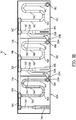
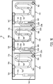
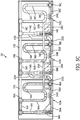
- FIGs. 1A-1G are plan views of a system for drying or curing tobacco leaves, according to an embodiment of the present disclosure.
- the system for drying or curing tobacco leaves 10 includes a plurality of chambers, housings or barns 12A, 12B and 12C configured for housing or receiving tobacco leaves (not shown).
- tobacco leaves can be hung on racks, strings, clips, tier poles, etc. provided inside the barns 12A, 12B, 12C, as is conventionally known.
- a heat source 14A, 14B and 14C Inside each of the barns 12A, 12B and 12C, respectively.
- the heat source 14A, 14B, 14C can be any type of heat source including a fuel combustion heat source such as a furnace, the fuel being selected from the group consisting of wood, biomass, coal, a liquefied petroleum gas (LPG), a liquefied natural gas (LNG), gasoline, alcohol, or any other combustible material, or any combination of two or more thereof.
- a fuel combustion heat source such as a furnace
- the fuel being selected from the group consisting of wood, biomass, coal, a liquefied petroleum gas (LPG), a liquefied natural gas (LNG), gasoline, alcohol, or any other combustible material, or any combination of two or more thereof.
- LPG liquefied petroleum gas
- LNG liquefied natural gas
- gasoline alcohol
- alcohol alcohol
- the hot combustion gases generated by the combustion of the fuel (e.g., wood, biomass, gas, etc.) in the heat sources 14A, 14B, 14C moves through flue pipes 16A, 16B and 16C, respectively.
- Flue pipes 16A are arranged in serpentine or meandering fashion inside barn 12A
- flue pipes 16B are arranged in serpentine or meandering fashion inside barn 12B
- flue pipes 16C are arranged in serpentine or meandering fashion inside barn 12C.
- the hot combustion gases flowing through the flue pipes 16A, 16B, and 16C heat the walls of the flue pipes.
- the heat is transmitted by conduction through the walls of the flue pipes 16A, 16B and 16C to the air surrounding the flue pipes 16A, 16B, 16C.
- flue pipes 16A in barn 12A, flue pipes 16B in barn 12B and flue pipes 16C in barn 12C are arranged at a lower portion of the barns 12A, 12B and 12C, closer to the floor of the barns 12A, 12B and 12C so that hot air heated by conduction through the wall of flue pipes 12A, 12B and 12C raises by heat convection to come in contact with tobacco leaves hung above the flue pipes 16A, 16B and 16C.
- Exhaust ports 18A, 18B, 18C are also provided at an end of flue pipes 16A, 16B and 16C, respectively.
- the exhaust ports 18A, 18B and 18C are configured to exhaust the combustion gases generated by the combustion of the fuel in the heat sources 14A, 14B and 14C into the atmosphere outside of the barns 12A, 12B and 12C. Therefore, the flue pipes 16A, 16B and 16C carrying hot combustion gas generated by the combustion of the fuel in the heat sources 14A, 14B and 14C, respectively, are configured to heat the air inside the barns 12A, 12B and 12C, respectively, to dry or cure the tobacco leaves housed inside the respective barns 12A, 12B and 12C.
- the system 10 further includes connecting flue pipe 20A that connects the flue pipes 16A in barn 12A with the flue pipes 16B in barn 12B and connecting flue pipe 20B that connects the flue pipes 16B in barn 12B with flue pipes 16C in barn 12C.
- the connecting flue pipe 20A is provided inside barn 12B and the connecting flue pipe 20B is provided inside barn 12C.
- a gate, register or damper 22A is provided at a junction 23A between the flue pipes 16A and the connecting flue pipe 20A.
- a gate, register or damper 22B is provided at a junction 25A between the flue pipes 16B and the connecting flue pipe 20B.
- the gate 22A is provided within barn 12A and gate 22B is provided within barn 12B.
- the gate 22A can be provided at any location within the connecting pipe 20A, for example at an end 23B of connecting pipe 20A that connects to flue pipes 16B within barn 12B.
- the gate 22B can be provided at any location within the connecting pipe 20B, for example at an end 25B of connecting pipe 20B that connects to flue pipes 16C within barn 12C.
- the register or damper 22A controls a flow of combustion gases from the flue pipes 16A to connecting flue pipe 20A.
- the register or damper 22B controls a flow of combustion gases from the flue pipes 16B to connecting flue pipe 20B.
- the gate 22A and the gate 22B can also be configured to be adjustable so as to allow a portion of the combustion gases to be redirected to flow into the connecting flue pipe 20A, 20B while allowing another portion of the combustion gases to exhaust to the outside atmosphere through exhaust ports18A, 18B.
- the barn 12A and the adjacent barn 12B share a common wall 13A and the barn 12B and the adjacent barn 12C share a common wall 13B.
- a common wall 13A between the adjacent barns 12A and 12B and/or a common wall 13B between adjacent barns 12B and 12C manufacturing costs of the barns 12A, 12B and 12C can be reduced.
- a length of connecting flue pipe 20A and/or connecting flue pipe 20B can be housed wholly inside the barn 12A, 12B and 12C, thus allowing to reduce heat dissipation outside of the barns 12A, 12B and 12C and thus efficiently using the heat of the combustion gases inside the respective barns to dry tobacco leaves.
- the barns are shown to be arranged as having a common wall between two adjacent barns, as it can be appreciated the barns 12A, 12, 12C can also be separated from each other so that a gap is provided between two adjacent walls of two respective barns, if desired.
- the combustion gases circulating or flowing inside the flue pipes 16A, 16B, 16C and connecting flue pipes 20A and 20B do not come in contact with tobacco leaves.
- the hot combustion gases circulating within the flue pipes 16A, 16B, 16C, 20A, 20B heat the walls of the flue pipes.
- the hot walls of the flue pipes in turn heat the air within the various barns 12A, 12B and/or 12C through heat conduction.
- the hot air moves by heat convection to cure and dry tobacco leaves hung inside the barns 12A, 12B and/or 12C.
- the barn 12A (a first barn) is filled with a first batch of tobacco leaves, before starting the heat source 14A, as illustrated in FIG. 1A .
- the tobacco leaves can be hung on racks, clips, strings or placed on shelves, or the like inside the barn 12A.
- the heat source 14A e.g., a furnace using wood, biomass, coal or gas such as LPG as fuel
- FIG. 1B is then started, as illustrated in FIG. 1B .
- Heat generated by the hot combustion gas generated by the combustion of the fuel in the heat source 14A flows through the flue pipes 16A and is used to heat the air inside the barn 12A to cure and dry the first batch of tobacco leaves hung inside the barn 12A, as illustrated in FIG. 1B .
- Heat generated by the hot combustion gas from the heat source 14A heats the walls of the flue pipes 16A.
- the heat from the walls of the flue pipes 16A is transmitted by conduction to the air surrounding the flue pipes 16A.
- the hot air then propagates via convection to contact the tobacco leaves to cure and dry the tobacco leaves (i.e., gradually remove the moisture within the tobacco leaves).
- the flue pipes 16A carrying the hot combustion gas generated by the combustion of the fuel in the heat source 14A is/are configured to heat the air inside the barn 12A to dry or cure the tobacco leaves housed inside the barn 12A.
- exhaust port 18A is closed and the gate, register or damper 22A is opened to allow the combustion gases from flue pipes 16A inside the barn 12A to transfer to flue pipes 16B inside the barn 12B, as illustrated in FIG. 1C .
- the time period T1 is between 36 hours and 48 hours (about 2 days) from the start of heat source 14A. In an embodiment, the time period T1 may also be dependent on the tobacco reaping capability of the grower. For example, faster reaping and filling of the second barn 12B allows the damper 22A to be opened earlier than the 36 hours.
- the barn 12A can be configured so that a certain amount of air will continue to be exhausted through exhaust port 18A to assist with the chimney-effect of removing moisture laden air from barn 12A.
- the heat from the transferred combustion gases is used to pre-heat or heat the air inside the barn 12B.
- the combustion gases transferred to the flue pipes 16B are exhaust through exhaust port 18B to outside atmosphere, as illustrated in FIG. 1C .
- a third batch of tobacco leaves are disposed or hung inside the barn 12C (a third barn).
- the exhaust port 18B is closed and the register or damper 22B is opened to allow the combustion gases to pass into the flue pipes 16C inside the barn 12C, as illustrated in FIG. 1D .
- the time period T2 is about 36 hours to 48 hours (about 2 days).
- the heat from the transferred combustion gases is used to pre-heat or heat the air inside the barn 12C.
- the combustion gases from flue pipes 16B inside barn 12B that transferred to flue pipes 16C inside barn 12C originate from the heat source 14A.
- the time period T2 may also be dependent on the tobacco reaping capability of the grower. For example, faster reaping and filling of the third barn 12C allows the damper 22B to be opened earlier than the 36 hours.
- the barn 12B can be configured so that a certain amount of air will continue to be exhausted through exhaust 18B to assist with the chimney-effect of removing moisture laden air from barn 12B.
- the heat source 14B is started and the heat source 14A is stopped (when the tobacco in barn 12A has finished curing), as illustrated in FIG. 1E .
- the time period T3 is between 36 hours and 48 hours (about 2 days).
- the heat generated by combustion gases from the heat source 14B continues to dry the second batch of leaves inside the barn 12B and dry the third batch of leaves in barn 12C, as illustrated in FIG. 1E .
- the combustion gases are allowed to exit through exhaust port 18C into the outside atmosphere, as illustrated in FIG. 1E . Therefore, the flue pipes 16B carrying the hot combustion gas generated by the combustion of the fuel in the heat source 14B is/are configured to heat the air inside the barn 12B to dry or cure the tobacco leaves housed inside the barn 12B.
- the heat source 14C is started and the heat source 14B is stopped (when the tobacco in barn 12B has finished curing), as illustrated in FIG. 1F .
- the time period T4 is between about 48 hours and 54 hours (about 4 days).
- the heat generated by the combustion gases from the heat source 14C continues to dry the third batch of leaves inside the barn 12C.
- the combustion gases are allowed to exit through exhaust port 18C to the outside atmosphere, as illustrated in FIG. 1F . Therefore, the flue pipes 16C carrying the hot combustion gases generated by the combustion of the fuel in the heat source 14C is/are configured to heat the air inside the barn 12C to dry or cure the tobacco leaves housed inside the barn 12C.
- heat generated by the heat source 14A is delivered to the barn 12A for approximately 6 days, delivered to the barn 12B for approximately 4 days, and delivered to the barn 12C for approximately 2 days.
- heat generated by the heat source 14B is delivered to barn 12B for approximately 2 days and delivered to barn 12C for approximately 2 days.
- the heat generated by the heat source 14C is delivered to barn 12C for approximately 2 days. Therefore, while the heat source 14A operates for a period of approximately 6 days, the heat source 14B and the heat source 14C both operate during a shorter period of time of only 2 days to all together dry or cure 3 batches of tobacco leaves.
- Table 1 summarizes the time of operation of each of the heat sources (HS) 14A.
- the above process can be repeated in a second cycle to cure and dry another series of three batches of tobacco leaves.
- a fourth batch of tobacco leaves can be loaded into the first barn 12A and cured and dried using the heat source 14A in the first barn 12A while the combustion gases from the heat source 14A are exhausted through exhaust port 18A to outside atmosphere, as illustrated in FIG. 1F .
- the third batch of tobacco leaves is in its final curing phase in the third barn 12C during a time period of approximately 2 days
- the fourth batch of tobacco leaves in the first barn 12A is in its first drying or curing phase which also has a time period of approximately 2 days.
- the second barn 12B is empty, as illustrated in FIG. 1F , and thus the second barn can be filled with a fifth batch of tobacco leaves.
- the exhaust port 18A is closed and the register 22A is opened and the combustion gases from the heat source 14A are introduced into the flue pipes 16B inside the barn 12B so as to start drying or curing the fifth batch of tobacco leaves, as illustrated in FIG. 1G .
- the remaining procedures are similar to the procedures described above with respect to curing the first, second and third batches of tobacco leaves.
- the present described method of curing tobacco leaves can be applied continuously by using the first barn 12A, the second barn 12B and the third barn 12C in rotation. This allows improving the efficiency of the overall curing system.
- the barns can also be used individually without using combustion gases from one heat source in one barn to another barn.
- bypass flue pipes 17A and 17B are also provided to allow, for example, bypassing the flue pipes 16A and/or 16B and thus not utilizing the barns 12A and/or 12B and employing the combustion gases from the heat source 14A located in barn 12A to dry or cure a batch of tobacco leaves deposited inside the barn 12B or the barn 12C.
- Another instance where the bypass pipes 17A and/or 17B may be utilized is when, for example, two heat sources may be used in tandem to dry a batch of tobacco leaves.
- bypass pipe 17A can be used to transfer the combustion gases from the heat source 14A into the flue pipes 16B within the barn 12B (without passing through the flue pipes 16A inside the barn 12A) while at the same time the combustion gases from the heat source 14B are also used so as to dry a batch of tobacco leaves deposed in the barn 12B.
- bypass pipes 17A and 17B can be used to increase temperatures in the adjacent barn if and when desired.
- combustion gas temperature at the entry point of bypass pipe 17A can be approximately 90 degrees Celsius hotter than at point of connecting flue pipe 20A
- the temperature in barn 12B can be increased to match drying/curing curve requirements.
- the temperature in barn 12C can be increased to match drying/curing curve requirements.
- the dampers 19A, 19B can be adjusted between 0% to 100% open depending on temperature requirements in the neighboring barn (respectively, barn 12B and barn 12C).
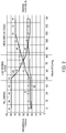
- FIG. 2 is a plot of change in temperature and relative humidity across the curing or drying time, according to an embodiment of the present disclosure.
- Curve 30 shows the variation of relative humidity as a function of curing time.
- Curve 31 shows the variation of temperature of a dry bulb as a function of drying or curing time.
- Curve 32 shows the variation of temperature of a humid or wet bulb as a function of drying or curing time.
- the curing or drying of the tobacco leaves can be divided into three stages:
- the temperature of dry bulb and humid or wet bulb remain at about 35 deg. C. with variation of approximately 2-3 deg. C. lower reading on the humid or wet bulb.
- the temperature of the dry bulb increase from about 35 deg. C to about 55 deg. C and the temperature of the humid or wet bulb increase slightly from about 35 deg. C to about 40 deg. C.
- the temperature of the dry bulb increase from about 55 deg. C to about 70 deg. C and the temperature of the humid or wet bulb increase slightly from about 40 deg. C to about 43 deg. C.
- the drying or curing time of tobacco bulb is approximately 144 hours (6 days).
- FIG. 3 is a diagram depicting a drying or curing cycle employing the three barns 12A, 12B and 12C, according to an embodiment of the present disclosure.
- the second barn 12B is used 36 hours to 48 hours (about 2 days) from the start of the first barn 12A to cure the second batch of tobacco leaves by initially using the combustion gases from the heat source 14A located in the first barn 12A by opening the register or damper 22A and then following by a full cure using the heat source 14B located in the second barn 12B.
- heating the second barn 12B is started after the temperature of the first batch of tobacco leaves reach the end of the yellowing stage.
- the third barn 12C is used 24 hours to 36 hours (about 2 days) from the start of the second barn 12B (i.e., 4 days from the opening of the register or damper 22A) to cure the third batch of tobacco leaves initially by using the combustion gases from the first heat source 14A, then by using the combustion gases from the second heat source 14B and finally to a final cure by using the third heat source 14C located in the third barn 12C.
- heating the third barn 12C is started after the temperature of the second batch of tobacco leaves has also reached the end of the yellowing stage.
- the start of barn 12C is also dependent on the tobacco reaping capability of the grower.
- damper 22B can be opened to allow the combustion gases in the flue pipes 16B to flow into the connecting flue pipe 20B.
- FIG. 4 is a plot of the ratio of cumulative curing fuel usage to tobacco mass as a function of the number of cures, according to an embodiment of the present disclosure.
- Curve 40 represents the variation of the ratio of fuel usage to the mass of tobacco leaves as a function of the number of consecutive number of cures in a conventional system without recycling the combustion gases from one barn to another barn. In this case, as expected, the ratio is equal to one as each barn uses fuel independently from the next barn.
- Curve 42 represents the variation of the ratio of fuel usage to the mass of tobacco leaves as a function of the number of consecutive number of cures in a system according to an embodiment of the present disclosure in which combustion gases from one barn are used in a neighboring barn, as described in the above paragraphs.
- the ratio decreases from 1 to approximately 0.74.
- the ratio is equal to one. Therefore, in the first barn 12A, the full amount of fuel is used by the heat source 14A to cure the full batch of tobacco leaves deposited in the first barn 12A.
- the ratio decreases to 0.8 due to the utilization of the combustion gases from the first heat source 14A located in the first barn 12A to cure second batch of leaves in the second barn 12B. In other words, the full utilization of the heat source 14B in the second barn is reduced by 20% by using the combustion gases from the first heat source 14A. This allows saving energy of burning less fuel to cure the second batch of tobacco leaves.
- the ratio is further reduced to 0.74 when curing the third batch of tobacco leaves due to the utilization of the combustion gases from the first heat source 14A located in the first barn 12A and the combustion gases from the second heat source 14B located in the second barn to cure third batch of tobacco leaves.
- the full utilization of the heat source 14C in the third barn is reduced by approximately 26% by using the combustion gases from the first heat source 14A and the second heat source 14B.
- the curing efficiency can be improved by using less fuel to achieve the same curing of tobacco leaves.
- Table 2 summarizes results of drying or curing tobacco leaves using individual independent barns. These results are obtained without using recirculating combustion gases from one heat source located in one barn into a second adjacent barn. As shown in Table 2, the ratio of fuel weight to the weight of dry tobacco leaves is approximately 1 independent of the barn used to dry the tobacco leaves.
- Table 3 summarizes results of drying or curing tobacco leaves using individual independent barns and using barns wherein combustion gases from one barn are using in the next barn in accordance with the process described above.
- the ratio of fuel weight to the weight of dry tobacco leaves is approximately 1 when independent barns are used in isolation.
- the ratio of fuel weight to the weight of dry tobacco leaves decreases from 1.02 to 0.58 and 0.67 when using the recycling of combustion gases from the first barn 12A to the second barn 12B and third barn 12C, respectively, as described in the above paragraphs.
- FIGs. 5A-5G are a plan views of a system for drying or curing tobacco leaves, according to another embodiment of the present disclosure.
- the system for drying or curing tobacco leaves 50 includes a plurality of chambers, housings or barns 52A, 52B and 52C configured for housing or receiving tobacco leaves (not shown).
- the barns 12A, 12B and 12C tobacco leaves can be hung on racks or the like that are provided inside the barns 52A, 52B, 52C, as is conventionally known.
- same reference numerals are used for similar components described above with respect to the system 10 comprising the barns 12A, 12B and 12C for curing tobacco leaves. Therefore, the description of the system with respect to these components will not be repeated in the following paragraphs.
- barns 52A, 52B and 52C of system 50 may be provided with a fan at location 54A, location 54B or location 54C.
- a same fan can be used in each barn 52A, 52B, 52C, at respective locations 54A, 54B, 54C.
- the same fan can be moved from location 54A to the location 54B or moved to location 54C.
- a piece of pipe or duct work can be used to complete the gap left by the removed fan at the location 54A.
- the fan at location 54A is connected to exhaust port 18A via flue pipe 56A and is connected to heat source 14A via return flue pipe 58A.
- the fan at location 54A is configured to return at least a portion of the combustion gases to the heat source 14A so as to increase the amount of flow of combustion gases that recirculate through the flue pipes 16A, as illustrated in FIG. 5B .
- the fan at location 54B is connected to exhaust port 18B via flue pipe 56B and is connected to heat source 14B via return flue pipe 58B.
- a bypass flue pipe 59A connects the return flue pipe 58B to the flue pipe 56A.
- the bypass flue pipe 59A allows to bypass the heat source 14B when desired to transfer the combustion gases drawn by the fan back to the heat source 14A, as illustrated in FIG. 5C , as will be described further in detail in the following paragraphs.
- bypass flue pipe 59B connects the return flue pipe 58C to the flue pipe 56B.
- the bypass flue pipe 59B allows to bypass the heat source 14C when desired to transfer the combustion gases drawn by the fan back to the heat source 14A or 14B, as will be described further in detail in the following paragraphs.
- register 22A while register 22A is closed the fan at location 54A recirculates hot combustion gases within barn 52A only, as shown in FIG. 5B .
- the fan at location 54A When register 22A is opened then the fan at location 54A recirculates hot gases through duct (flue pipes) 56B, 58B, 59A, 56A and 58A back to heat source 14A, as shown in FIG. 5C .
- the fan at location 54A recirculates hot gases through duct (flue pipes) 56C, 58C, 59B, 56B, 58B, 59A, 56A and 58A back to heat source 14A, as shown in FIG. 5D .
- the fan positioned at location 54A, location 54B or location 54C can be energized using electrical energy if available.
- the electrical energy can be supplied through the electrical grid or supplied by converting solar energy using solar panels and/or electrical batteries, or using an electric generator that employs LPG, gasoline or other form of fuel.
- the fans can be used regardless of the type of fuel used in the heat sources 14A, 14B and 14C be it wood, coal, or LPG, etc.
- the barn 52A is filled with a first batch of tobacco leaves, before starting the heat source 14A, as illustrated in FIG. 5A .
- the tobacco leaves can be hung on racks, or placed on shelves or the like inside the barn 52A.
- the heat source 14A e.g., a furnace using wood, coal or gas as fuel
- FIG. 5B is then started, as illustrated in FIG. 5B .
- Heat generated by the hot combustion gases generated by the combustion of the fuel in the heat source 14A flows through the flue pipes 16A and is used to heat the air inside the barn 52A to dry the first batch of tobacco leaves hung inside the barn 52A, as illustrated in FIG. 5B .
- Heat generated by the hot combustion gas from the heat source 14A heats the walls of the flue pipes 16A.
- the heat from the walls of the flue pipes 16A is transmitted by conduction to the air surrounding the flue pipes 16A.
- the hot air then propagates through convection to contact the tobacco leaves to dry the tobacco leaves (i.e., gradually remove the moisture within the tobacco leaves).
- the gate, register or damper 22A is opened to allow the combustion gases from flue pipes 16A inside the barn 52A to transfer to flue pipes 16B inside the barn 52B, as illustrated in FIG. 5C .
- the time period T1 is between 36 hours and 48 hours (about 2 days) from the start of heat source 14A.
- the heat from the transferred combustion gases is used to pre-heat the air inside the barn 52B.
- a portion of the combustion gases transferred to the flue pipes 16B are recycled and are sent back towards the heat source 14A using the fan located at location 54A via flue pipe 56B, flue pipe 58B, the bypass flue pipe 59A, flue pipe 56A, and flue pipe 58A, as illustrated in FIG. 5C .
- a third batch of tobacco leaves are disposed or hung inside the barn 52C.
- the register or damper 22B is opened to allow the combustion gases to pass into the flue pipes 16C inside the barn 12C, as illustrated in FIG. 5D .
- the time period T2 is about 36 hours to 48 hours (about 2 days). The heat from the transferred combustion gases is used to pre-heat the air inside the barn 52C.
- the combustion gases from flue pipes 16B inside barn 12B that transferred to flue pipes 16C inside barn 52C originate from the heat source 14A.
- heat source 14A only heat source 14A is operating and combustion gases from heat source 14A are used to heat barn 52A, barn 52B and barn 52C, as illustrated in FIG. 5D .
- the combustion gases transferred to the flue pipes 16C are recycled and are sent back towards the heat source 14A using the fan located at location 54A via, flue pipes 56C, 58C, the bypass flue pipe 59B, flue pipe 56B, flue pipe 58B, bypass flue pipe 59A, flue pipe 56A, and flue pipe 58A, as illustrated in FIG. 5D .
- the heat source 14B is started and the heat source 14A is stopped (when tobacco has finished curing in barn 12A), as illustrated in FIG. 5E .
- the time period T3 is between 36 hours and 48 hours (about 2 days).
- the heat generated by combustion gases from the heat source 14B continues to dry the second batch of leaves inside the barn 52B and dry the third batch of leaves in barn 52C, as illustrated in FIG. 5E .
- the fan is moved to location 54B.
- the heat source 14C is started and the heat source 14B is stopped, as illustrated in FIG. 5F .
- the time period T4 is between about 48 hours and 54 hours (about 4 days).
- the heat generated by combustion gases from the heat source 14C continues to further dry the third batch of leaves inside the barn 52C.
- the fan can be moved to the location 54C and the combustion gases can be recirculated using the fan at location 54C.
- the fan at location 54C pushes the combustion gases back towards the heat source 14B or towards the heat source 14A to heat the barns 52B or 52A, respectively.
- the above process can be repeated in a second cycle to dry another series of three batches of tobacco leaves.
- a fourth batch of tobacco leaves can be loaded into the first barn 52A and dried using the heat source 14A in the first barn 52A while the combustion gases from the heat source 14A are recycled and sent back towards the heat source 14A using the fan that is moved back to location 54A, as illustrated in FIG. 5F .
- the heat generated by combustion gases from the heat source 14C can be used to heat barn 52A for approximately the first two days of the curing cycle and when barn 52C has finished its cure, the heat source 14A can be started.
- the fourth batch of tobacco leaves in the first barn 52A is in its first drying or curing phase which also has a time period of approximately 2 days.
- the second barn 12B is empty and thus the second barn can be filled with a fifth batch of tobacco leaves, as illustrated in FIG. 5F .
- the register 22A is opened and the combustion gases from the heat source 14A are introduced into the flue pipes 16B inside the barn 12B so as to start drying or curing the fifth batch of tobacco leaves, as illustrated in FIG. 5G .
- the combustion gases in fuel pipe 16B are recycled and send back toward heat source 14A using the fan at location 54A, as shown in FIG. 5G .
- the remaining procedures are similar to the procedures described above with respect to curing the first, second and third batches of tobacco leaves.
- the present described method of curing tobacco leaves can be applied continuously by using the first barn 52A, the second barn 52B and the third barn 52C in rotation.
- the fans at successive locations 54A, 54B and 54C along with the bypass flue pipes 59A, and 59B the curing efficiency is further enhanced as the combustion gases are recycled for use for curing the tobacco leaves.
- the use of the fan at the various locations 54A, 54B and 54C requires the use of an additional source of energy such as electrical power delivered by the electrical grid, using solar energy or batteries or using an electric generator that employs LPG, gasoline or other form of fuel.
- the heat sources 14A, 14B and 14C can be provided with or without a Venturi system in the case of using LPG or other suitable fuel.
- the system of recycling of combustion gases using the fan at location 54A, 54B or 54C is applicable for any type of heat source using any type of fuel.
- the estimated fuel usage decreases from about 1 to about 0.6 over 18 consecutive cures in an average tobacco curing season.
- Table 4 summarizes comparative results between drying or curing tobacco leaves using individual independent barns and using barns wherein combustion gases from one barn are used in the next barn in accordance with the process described above.
- the present results are obtained using a heat source provided or fitted with a Venturi system with LPG as the fuel system.
- the cumulative ratio of fuel weight to the weight of dry tobacco leaves is approximately 0.88, 0.84 and 0.85, for the barns 14A, 14B and 14C when used independently from each other.
- the cumulative ratio of fuel weight to the weight of dry tobacco leaves decreases from 0.88 to 0.70 and then to 0.67 when using the recycling of combustion gases from the first barn 12A to the second barn 12B and third barn 12C, respectively, as described in the above paragraphs.
- FIG. 6 is a plot of ratios of the weight of LPG to the weight of dried or cured tobacco leaves when using the barns independently and when using the barns consecutively with a recirculation of combustion gases from one barn to another barn, according to an embodiment of the present disclosure.
- Curve 60 represents the variation of the ratio of fuel (in this case LPG) usage to the weight of dried tobacco leaves as a function of the number of consecutive number of cures in a conventional system without recycling the combustion gases from one barn to another barn.
- the ratio is substantially constant and equal to approximately 0.88 as each barn uses fuel independently from the next barn and each barn uses the same amount of fuel (LPG) to dry a batch of tobacco leaves.
- Curve 62 represents the variation of the ratio of fuel (in this case LPG) usage to the weight of tobacco leaves as a function of the number of consecutive number of cures in a system according to an embodiment of the present disclosure in which combustion gases from one barn are used in a neighboring barn, as described in the above paragraphs.
- the ratio decreases from 0.88 to approximately 0.67, at the third consecutive cure, i.e., at the third barn 12C or decreases to about 0.64 at a fourth (3+1) consecutive cure, i.e, when repeating the process at the first barn 12A.
- the ratio is equal to 0.88.
- the ratio is 0.88 to 1.
- the ratio decreases to 0.72 due to the utilization of the combustion gases from the first heat source 14A located in the first barn 12A to cure second batch of leaves in the second barn 12B.
- the full utilization of the heat source 14B in the second barn is reduced by approximately 16% by using the combustion gases from the first heat source 14A, when using LPG with a Venturi system. This allows saving energy of burning less fuel to cure the second batch of tobacco leaves.
- the ratio is further reduced to 0.67 when curing the third batch of tobacco leaves due to the utilization of the combustion gases from the first heat source 14A located in the first barn 12A and the combustion gases from the second heat source 14B located in the second barn to cure third batch of tobacco leaves.
- the full utilization of the heat source 14C in the third barn is reduced by approximately 21 % by using the combustion gases from the first heat source 14A and the second heat source 14B.
- the curing efficiency can be improved by using less fuel to achieve the same curing of tobacco leaves.
- the above results are obtained for a certain variety of tobacco, and another variety of tobacco may lead to slightly different results.
- the ratio of fuel usage can be decreased while achieving the desired curing and thus the overall curing efficiency can be enhanced.
- FIG. 7 is a bar-graph indicating a ratio of energy usage to weight of cured or dried tobacco leaves with LPG without using a Venturi system, in accordance with an embodiment of the present disclosure.
- Bar graph 70 shows a plurality of bars corresponding to the ratio of energy (in MJ) to the weight of cured tobacco when using LPG as fuel without a Venturi system.
- Bar 70A corresponds to the ratio of LPG energy to weight of cured tobacco when using a conventional tobacco curing system with recycling the combustion gases from one barn to another barn (Standard LPG).
- Bar 70B corresponds to the ratio of LPG energy to weight of cured tobacco when using the system for recycling the combustion gases from one barn to another barn (Turbo LPG). As shown, the ratio decreases from about 46 to about 35 which is equivalent to energy savings of about 24%.
- FIG. 8 is a bar-graph indicating a ratio of energy usage to weight of cured or dried tobacco leaves with LPG with a Venturi system, in accordance with an embodiment of the present disclosure.
- Bar graph 80 shows a plurality of bars corresponding to the ratio of energy (in MJ) to the weight of cured tobacco when using LPG as fuel with a Venturi system.
- Bar 80A corresponds to the ratio of LPG energy to weight of cured tobacco when using a conventional tobacco curing system without recycling the combustion gases from one barn to another barn (Standard LPG).
- Bar 80B corresponds to the ratio of LPG energy to weight of cured tobacco when using the system for recycling the combustion gases from one barn to another barn (Turbo LPG). As shown, the ratio decreases from about 40 to about 29 which is equivalent to energy savings of about 28%.
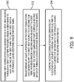
- FIG. 9 depicts a flow diagram of a method for curing or drying tobacco leaves according to an embodiment of the present disclosure.
- the method includes flowing first combustion gas generated by a first heat source through a first flue pipe provided inside a first barn to heat air inside the first barn to dry a first batch of tobacco leaves disposed inside the first barn, at S10; transferring at least a portion of the first combustion gas generated by the first heat source to a second flue pipe provided inside a second barn adjacent the first barn to heat the second barn and start drying a second batch of tobacco leaves disposed inside the second barn, at S12; and flowing second combustion gas generated by a second heat source through the second flue pipe to continue drying the second batch of tobacco leaves after the second barn is heated, at S14.
- the method prior to flowing the first combustion gas through the first flue pipe, includes disposing the first batch of tobacco leaves inside the first barn and starting the first heat source and generating the first combustion gas by combustion of fuel in the first heat source. In an embodiment, the method includes disposing the second batch of tobacco leaves inside the second barn while the first batch of tobacco leaves is drying in the first barn.
- the method includes starting the second heat source and generating the second combustion gas by combustion of fuel in the second heat source. In an embodiment, prior to starting the second heat source, stopping the first heat source.
- transferring at least a portion of the first combustion gas generated by the first heat source to the second flue pipe includes opening a register provided between the first flue pipe and the second flue pipe.
- the method prior to flowing the second combustion gas generated by the second heat source through the second flue pipe to continue drying the second batch of tobacco leaves, the method includes transferring at least a portion of the first combustion gas generated by the first heat source to a third flue pipe provided inside a third barn adjacent to the second barn to heat the third barn and start drying a third batch of tobacco leaves disposed inside the third barn.
- transferring at least a portion of the first combustion gas generated by the first heat source to the third flue pipe includes opening a register provided between the second flue pipe and the third flue pipe.
- the method further includes flowing third combustion gas generated by a third heat source provided in the third barn through the third flue pipe to continue drying the third batch of tobacco leaves.
- the method when using a fan, includes flowing third combustion gases back to the first barn to start the curing process in the first barn.
- the present system and method of reusing combustion gases from one barn into another barn increases the overall tobacco leaves drying efficiency and provides energy savings regardless of the type of fuel used.
Landscapes
- Life Sciences & Earth Sciences (AREA)
- Agronomy & Crop Science (AREA)
- Chemical & Material Sciences (AREA)
- Oil, Petroleum & Natural Gas (AREA)
- Drying Of Solid Materials (AREA)
- Organic Chemistry (AREA)
- Engineering & Computer Science (AREA)
- General Chemical & Material Sciences (AREA)
- Chemical Kinetics & Catalysis (AREA)
- Environmental & Geological Engineering (AREA)
- General Life Sciences & Earth Sciences (AREA)
- Geochemistry & Mineralogy (AREA)
- Geology (AREA)
- Biodiversity & Conservation Biology (AREA)
- Ecology (AREA)
- Forests & Forestry (AREA)
- Wood Science & Technology (AREA)
- Manufacture Of Tobacco Products (AREA)
Applications Claiming Priority (1)
| Application Number | Priority Date | Filing Date | Title |
|---|---|---|---|
| US15/387,371 US10342250B2 (en) | 2016-12-21 | 2016-12-21 | System and method for curing tobacco |
Publications (2)
| Publication Number | Publication Date |
|---|---|
| EP3338566A1 true EP3338566A1 (de) | 2018-06-27 |
| EP3338566B1 EP3338566B1 (de) | 2020-01-08 |
Family
ID=58185327
Family Applications (1)
| Application Number | Title | Priority Date | Filing Date |
|---|---|---|---|
| EP17157803.2A Active EP3338566B1 (de) | 2016-12-21 | 2017-02-24 | System und verfahren zum trocknen von tabak |
Country Status (7)
| Country | Link |
|---|---|
| US (1) | US10342250B2 (de) |
| EP (1) | EP3338566B1 (de) |
| AP (1) | AP2017009754A0 (de) |
| BR (1) | BR112017018716B1 (de) |
| GT (1) | GT201700196A (de) |
| MX (1) | MX385849B (de) |
| WO (1) | WO2018115981A1 (de) |
Cited By (1)
| Publication number | Priority date | Publication date | Assignee | Title |
|---|---|---|---|---|
| CN110063514A (zh) * | 2019-04-29 | 2019-07-30 | 广东中烟工业有限责任公司 | 一种小型气流烘丝实验装置 |
Families Citing this family (19)
| Publication number | Priority date | Publication date | Assignee | Title |
|---|---|---|---|---|
| CN106931734A (zh) * | 2017-04-20 | 2017-07-07 | 眉山市民威林产制品有限公司 | 一种节省能耗的蚊香烘干装置及方法 |
| CN106958990A (zh) * | 2017-04-20 | 2017-07-18 | 眉山市民威林产制品有限公司 | 一种提高蚊香质量的余热缓降装置及方法 |
| CN109875089A (zh) * | 2018-12-29 | 2019-06-14 | 德宏州高达化工实业有限责任公司 | 一种基于天然气燃烧机为能源供给的环保烤烟房 |
| CN111758990A (zh) * | 2019-04-01 | 2020-10-13 | 郭琳 | 天然气烘烤烟叶设备 |
| CN110260357B (zh) * | 2019-06-26 | 2020-08-14 | 西安圣华农业科技股份有限公司 | 一种生物质颗粒燃烧系统的控制方法 |
| CN111197915A (zh) * | 2020-01-21 | 2020-05-26 | 上海伯涵热能科技有限公司 | 一种防止热泵热水机组泵吸入口汽蚀的装置及烤房系统 |
| CN111602837A (zh) * | 2020-05-22 | 2020-09-01 | 廖福霖 | 一种液体燃料烘烤鲜烟叶工艺 |
| CN112120269A (zh) * | 2020-10-22 | 2020-12-25 | 云南省烟草农业科学研究院 | 一种烟草烘烤用醇基燃料及提高烟叶外观质量的烘烤方法 |
| CN112841698B (zh) * | 2021-01-19 | 2022-08-09 | 河南省烟草公司南阳市公司 | 一种可切换天然气和燃煤两种供热方式的烟叶密集烤房 |
| CN112998301B (zh) * | 2021-03-18 | 2023-04-07 | 贵州省烟草公司遵义市公司桐梓分公司 | 一种烤烟焖排烤软烤亮烘烤方法 |
| CN113331457B (zh) * | 2021-06-24 | 2023-04-14 | 安徽信息工程学院 | 一种烟草烘烤架以及烟草烘烤方法 |
| CN113455689B (zh) * | 2021-08-06 | 2022-07-15 | 湖南省烟草公司郴州市公司 | 一种减少湘烟6号挂灰烟的烘烤方法 |
| CN113647663B (zh) * | 2021-09-18 | 2024-09-06 | 贵州省烟草公司六盘水市公司 | 一种余热利用式烤房及换热方法 |
| CN114413611A (zh) * | 2022-02-11 | 2022-04-29 | 云南省烟草农业科学研究院 | 雪茄烟晾房的送风道结构 |
| CN114440572B (zh) * | 2022-02-14 | 2023-02-17 | 珠海格力电器股份有限公司 | 用于烟草烘干的热泵烘干机组的控制方法及热泵烘干机组 |
| CN114532567B (zh) * | 2022-03-30 | 2024-01-09 | 中国烟草总公司福建省公司 | 一种密集烤房结构及气水分离排湿与湿球温度控制方法 |
| CN114893963B (zh) * | 2022-06-06 | 2023-10-24 | 四川省烟草公司广元市公司 | 一种用于烟草农业的高效烘干室 |
| CN115804463A (zh) * | 2022-12-13 | 2023-03-17 | 中国烟草总公司重庆市公司奉节分公司 | 烤烟三段七步式烟夹烘烤方法 |
| CN118537439B (zh) * | 2024-05-14 | 2024-11-08 | 北京香田智能科技有限公司 | 一种烘烤曲线的处理方法 |
Citations (5)
| Publication number | Priority date | Publication date | Assignee | Title |
|---|---|---|---|---|
| US4267645A (en) * | 1979-10-22 | 1981-05-19 | Hill Edwin W | Burner-fired combined with wood-fired apparatus for drying crops |
| US4499911A (en) * | 1980-12-09 | 1985-02-19 | Johnson William H | Energy efficient curing and drying system |
| US5685710A (en) * | 1994-05-12 | 1997-11-11 | Martinez Sagrera; Jorge | Barn and procedure for Virginia type tobacco curing |
| US20060168842A1 (en) * | 2005-01-31 | 2006-08-03 | Sprague Michael M | Heat recovery and ventilation system for dryers |
| CN201388517Y (zh) * | 2009-04-07 | 2010-01-27 | 张鑫珩 | 一种模块组合式烤烟炉 |
Family Cites Families (8)
| Publication number | Priority date | Publication date | Assignee | Title |
|---|---|---|---|---|
| US3910757A (en) * | 1973-08-17 | 1975-10-07 | Miller Taylor | Mobile tobacco curing and drying system |
| US4123221A (en) | 1976-12-27 | 1978-10-31 | Harrington Manufacturing Company | Bulk tobacco curing and drying structure |
| US4206554A (en) * | 1978-09-18 | 1980-06-10 | Fowler Joe W | Heat cycling apparatus and method for bulk curing tobacco |
| US4263721A (en) | 1979-12-14 | 1981-04-28 | Danford Tiras J | Energy efficient bulk tobacco curing and drying structure |
| US4424024A (en) * | 1981-11-16 | 1984-01-03 | Powell Manufacturing Company, Inc. | Bulk curing with solid fuel |
| US5018281A (en) * | 1990-11-15 | 1991-05-28 | Bulluck Jr S Thomas | Tobacco barn with heat exchanger system |
| US8151804B2 (en) | 2008-12-23 | 2012-04-10 | Williams Jonnie R | Tobacco curing method |
| CN101843358B (zh) | 2010-04-23 | 2012-08-08 | 山东潍坊烟草有限公司 | 一种余热共享连体密集烤房及其操作使用方法 |
-
2016
- 2016-02-09 AP AP2017009754A patent/AP2017009754A0/en unknown
- 2016-12-21 US US15/387,371 patent/US10342250B2/en active Active
-
2017
- 2017-02-24 EP EP17157803.2A patent/EP3338566B1/de active Active
- 2017-02-27 MX MX2017011238A patent/MX385849B/es unknown
- 2017-02-27 BR BR112017018716-7A patent/BR112017018716B1/pt active IP Right Grant
- 2017-02-27 WO PCT/IB2017/051148 patent/WO2018115981A1/en not_active Ceased
- 2017-09-01 GT GT201700196A patent/GT201700196A/es unknown
Patent Citations (5)
| Publication number | Priority date | Publication date | Assignee | Title |
|---|---|---|---|---|
| US4267645A (en) * | 1979-10-22 | 1981-05-19 | Hill Edwin W | Burner-fired combined with wood-fired apparatus for drying crops |
| US4499911A (en) * | 1980-12-09 | 1985-02-19 | Johnson William H | Energy efficient curing and drying system |
| US5685710A (en) * | 1994-05-12 | 1997-11-11 | Martinez Sagrera; Jorge | Barn and procedure for Virginia type tobacco curing |
| US20060168842A1 (en) * | 2005-01-31 | 2006-08-03 | Sprague Michael M | Heat recovery and ventilation system for dryers |
| CN201388517Y (zh) * | 2009-04-07 | 2010-01-27 | 张鑫珩 | 一种模块组合式烤烟炉 |
Cited By (1)
| Publication number | Priority date | Publication date | Assignee | Title |
|---|---|---|---|---|
| CN110063514A (zh) * | 2019-04-29 | 2019-07-30 | 广东中烟工业有限责任公司 | 一种小型气流烘丝实验装置 |
Also Published As
| Publication number | Publication date |
|---|---|
| WO2018115981A1 (en) | 2018-06-28 |
| MX385849B (es) | 2025-03-18 |
| BR112017018716A2 (pt) | 2018-08-07 |
| MX2017011238A (es) | 2019-09-16 |
| US10342250B2 (en) | 2019-07-09 |
| GT201700196A (es) | 2018-12-06 |
| AP2017009754A0 (en) | 2017-02-28 |
| BR112017018716B1 (pt) | 2022-11-08 |
| EP3338566B1 (de) | 2020-01-08 |
| US20180168218A1 (en) | 2018-06-21 |
Similar Documents
| Publication | Publication Date | Title |
|---|---|---|
| EP3338566B1 (de) | System und verfahren zum trocknen von tabak | |
| US8881425B2 (en) | System and method for drying wood products with recovered flue gas | |
| US6742284B2 (en) | Energy efficient tobacco curing and drying system with heat pipe heat recovery | |
| US10082335B2 (en) | Single pass continuous lumber drying kiln | |
| US8844159B2 (en) | System and method for drying wood | |
| EP0719503A1 (de) | Einrichtung und verfahren zum trocknen von tabak | |
| CN214172902U (zh) | 一种高效节能型隧道窑 | |
| US20130071800A1 (en) | Method for firing raw ceramic blanks and furnace | |
| US5018281A (en) | Tobacco barn with heat exchanger system | |
| US11181319B2 (en) | Sawed wood drying system with secondary air circulation | |
| JPS606138A (ja) | ひなふ化設備の稼動方法及び装置 | |
| JP7021843B2 (ja) | ウッドチップを乾燥するための方法及び装置 | |
| CZ286205B6 (cs) | Zařízení pro sušení a/nebo vypalování keramického zboží | |
| CN103776243A (zh) | 一种药材食品烘干设备 | |
| US3105713A (en) | Apparatus for bulk curing tobacco | |
| CN201709375U (zh) | 密集烤烟叠层紧凑优化型节能烤房 | |
| US1809628A (en) | Means for utilizing the waste gases from furnaces | |
| CN106338189A (zh) | 烘干系统 | |
| US115734A (en) | Improvement in brick-kilns | |
| US2956523A (en) | Oven heating system | |
| US1641585A (en) | Brickmaking plant | |
| US1054040A (en) | Apparatus for treating brick. | |
| US20260085889A1 (en) | Curing oven system for building materials and method for operating a curing oven system | |
| US2428169A (en) | Kiln system and method of operation | |
| JPS6349729B2 (de) |
Legal Events
| Date | Code | Title | Description |
|---|---|---|---|
| PUAI | Public reference made under article 153(3) epc to a published international application that has entered the european phase |
Free format text: ORIGINAL CODE: 0009012 |
|
| STAA | Information on the status of an ep patent application or granted ep patent |
Free format text: STATUS: THE APPLICATION HAS BEEN PUBLISHED |
|
| AK | Designated contracting states |
Kind code of ref document: A1 Designated state(s): AL AT BE BG CH CY CZ DE DK EE ES FI FR GB GR HR HU IE IS IT LI LT LU LV MC MK MT NL NO PL PT RO RS SE SI SK SM TR |
|
| AX | Request for extension of the european patent |
Extension state: BA ME |
|
| STAA | Information on the status of an ep patent application or granted ep patent |
Free format text: STATUS: REQUEST FOR EXAMINATION WAS MADE |
|
| 17P | Request for examination filed |
Effective date: 20181220 |
|
| RBV | Designated contracting states (corrected) |
Designated state(s): AL AT BE BG CH CY CZ DE DK EE ES FI FR GB GR HR HU IE IS IT LI LT LU LV MC MK MT NL NO PL PT RO RS SE SI SK SM TR |
|
| RIC1 | Information provided on ipc code assigned before grant |
Ipc: A24B 1/02 20060101AFI20190523BHEP Ipc: A24B 3/12 20060101ALI20190523BHEP Ipc: C10L 1/06 20060101ALI20190523BHEP Ipc: C10L 1/02 20060101ALI20190523BHEP |
|
| INTG | Intention to grant announced |
Effective date: 20190617 |
|
| GRAS | Grant fee paid |
Free format text: ORIGINAL CODE: EPIDOSNIGR3 |
|
| STAA | Information on the status of an ep patent application or granted ep patent |
Free format text: STATUS: GRANT OF PATENT IS INTENDED |
|
| GRAJ | Information related to disapproval of communication of intention to grant by the applicant or resumption of examination proceedings by the epo deleted |
Free format text: ORIGINAL CODE: EPIDOSDIGR1 |
|
| GRAL | Information related to payment of fee for publishing/printing deleted |
Free format text: ORIGINAL CODE: EPIDOSDIGR3 |
|
| STAA | Information on the status of an ep patent application or granted ep patent |
Free format text: STATUS: REQUEST FOR EXAMINATION WAS MADE |
|
| INTC | Intention to grant announced (deleted) | ||
| GRAR | Information related to intention to grant a patent recorded |
Free format text: ORIGINAL CODE: EPIDOSNIGR71 |
|
| STAA | Information on the status of an ep patent application or granted ep patent |
Free format text: STATUS: GRANT OF PATENT IS INTENDED |
|
| GRAA | (expected) grant |
Free format text: ORIGINAL CODE: 0009210 |
|
| STAA | Information on the status of an ep patent application or granted ep patent |
Free format text: STATUS: THE PATENT HAS BEEN GRANTED |
|
| AK | Designated contracting states |
Kind code of ref document: B1 Designated state(s): AL AT BE BG CH CY CZ DE DK EE ES FI FR GB GR HR HU IE IS IT LI LT LU LV MC MK MT NL NO PL PT RO RS SE SI SK SM TR |
|
| INTG | Intention to grant announced |
Effective date: 20191203 |
|
| REG | Reference to a national code |
Ref country code: GB Ref legal event code: FG4D |
|
| REG | Reference to a national code |
Ref country code: CH Ref legal event code: EP |
|
| REG | Reference to a national code |
Ref country code: DE Ref legal event code: R096 Ref document number: 602017010524 Country of ref document: DE |
|
| REG | Reference to a national code |
Ref country code: IE Ref legal event code: FG4D |
|
| REG | Reference to a national code |
Ref country code: AT Ref legal event code: REF Ref document number: 1221559 Country of ref document: AT Kind code of ref document: T Effective date: 20200215 |
|
| REG | Reference to a national code |
Ref country code: NL Ref legal event code: MP Effective date: 20200108 |
|
| REG | Reference to a national code |
Ref country code: GR Ref legal event code: EP Ref document number: 20200400324 Country of ref document: GR Effective date: 20200511 |
|
| REG | Reference to a national code |
Ref country code: LT Ref legal event code: MG4D |
|
| PG25 | Lapsed in a contracting state [announced via postgrant information from national office to epo] |
Ref country code: FI Free format text: LAPSE BECAUSE OF FAILURE TO SUBMIT A TRANSLATION OF THE DESCRIPTION OR TO PAY THE FEE WITHIN THE PRESCRIBED TIME-LIMIT Effective date: 20200108 Ref country code: NO Free format text: LAPSE BECAUSE OF FAILURE TO SUBMIT A TRANSLATION OF THE DESCRIPTION OR TO PAY THE FEE WITHIN THE PRESCRIBED TIME-LIMIT Effective date: 20200408 Ref country code: LT Free format text: LAPSE BECAUSE OF FAILURE TO SUBMIT A TRANSLATION OF THE DESCRIPTION OR TO PAY THE FEE WITHIN THE PRESCRIBED TIME-LIMIT Effective date: 20200108 Ref country code: PT Free format text: LAPSE BECAUSE OF FAILURE TO SUBMIT A TRANSLATION OF THE DESCRIPTION OR TO PAY THE FEE WITHIN THE PRESCRIBED TIME-LIMIT Effective date: 20200531 Ref country code: NL Free format text: LAPSE BECAUSE OF FAILURE TO SUBMIT A TRANSLATION OF THE DESCRIPTION OR TO PAY THE FEE WITHIN THE PRESCRIBED TIME-LIMIT Effective date: 20200108 Ref country code: RS Free format text: LAPSE BECAUSE OF FAILURE TO SUBMIT A TRANSLATION OF THE DESCRIPTION OR TO PAY THE FEE WITHIN THE PRESCRIBED TIME-LIMIT Effective date: 20200108 |
|
| PG25 | Lapsed in a contracting state [announced via postgrant information from national office to epo] |
Ref country code: BG Free format text: LAPSE BECAUSE OF FAILURE TO SUBMIT A TRANSLATION OF THE DESCRIPTION OR TO PAY THE FEE WITHIN THE PRESCRIBED TIME-LIMIT Effective date: 20200408 Ref country code: IS Free format text: LAPSE BECAUSE OF FAILURE TO SUBMIT A TRANSLATION OF THE DESCRIPTION OR TO PAY THE FEE WITHIN THE PRESCRIBED TIME-LIMIT Effective date: 20200508 Ref country code: SE Free format text: LAPSE BECAUSE OF FAILURE TO SUBMIT A TRANSLATION OF THE DESCRIPTION OR TO PAY THE FEE WITHIN THE PRESCRIBED TIME-LIMIT Effective date: 20200108 Ref country code: LV Free format text: LAPSE BECAUSE OF FAILURE TO SUBMIT A TRANSLATION OF THE DESCRIPTION OR TO PAY THE FEE WITHIN THE PRESCRIBED TIME-LIMIT Effective date: 20200108 Ref country code: HR Free format text: LAPSE BECAUSE OF FAILURE TO SUBMIT A TRANSLATION OF THE DESCRIPTION OR TO PAY THE FEE WITHIN THE PRESCRIBED TIME-LIMIT Effective date: 20200108 |
|
| REG | Reference to a national code |
Ref country code: DE Ref legal event code: R119 Ref document number: 602017010524 Country of ref document: DE |
|
| REG | Reference to a national code |
Ref country code: BE Ref legal event code: MM Effective date: 20200229 |
|
| PG25 | Lapsed in a contracting state [announced via postgrant information from national office to epo] |
Ref country code: MC Free format text: LAPSE BECAUSE OF FAILURE TO SUBMIT A TRANSLATION OF THE DESCRIPTION OR TO PAY THE FEE WITHIN THE PRESCRIBED TIME-LIMIT Effective date: 20200108 Ref country code: RO Free format text: LAPSE BECAUSE OF FAILURE TO SUBMIT A TRANSLATION OF THE DESCRIPTION OR TO PAY THE FEE WITHIN THE PRESCRIBED TIME-LIMIT Effective date: 20200108 Ref country code: ES Free format text: LAPSE BECAUSE OF FAILURE TO SUBMIT A TRANSLATION OF THE DESCRIPTION OR TO PAY THE FEE WITHIN THE PRESCRIBED TIME-LIMIT Effective date: 20200108 Ref country code: CZ Free format text: LAPSE BECAUSE OF FAILURE TO SUBMIT A TRANSLATION OF THE DESCRIPTION OR TO PAY THE FEE WITHIN THE PRESCRIBED TIME-LIMIT Effective date: 20200108 Ref country code: LU Free format text: LAPSE BECAUSE OF NON-PAYMENT OF DUE FEES Effective date: 20200224 Ref country code: SM Free format text: LAPSE BECAUSE OF FAILURE TO SUBMIT A TRANSLATION OF THE DESCRIPTION OR TO PAY THE FEE WITHIN THE PRESCRIBED TIME-LIMIT Effective date: 20200108 Ref country code: EE Free format text: LAPSE BECAUSE OF FAILURE TO SUBMIT A TRANSLATION OF THE DESCRIPTION OR TO PAY THE FEE WITHIN THE PRESCRIBED TIME-LIMIT Effective date: 20200108 Ref country code: SK Free format text: LAPSE BECAUSE OF FAILURE TO SUBMIT A TRANSLATION OF THE DESCRIPTION OR TO PAY THE FEE WITHIN THE PRESCRIBED TIME-LIMIT Effective date: 20200108 Ref country code: DK Free format text: LAPSE BECAUSE OF FAILURE TO SUBMIT A TRANSLATION OF THE DESCRIPTION OR TO PAY THE FEE WITHIN THE PRESCRIBED TIME-LIMIT Effective date: 20200108 |
|
| PLBE | No opposition filed within time limit |
Free format text: ORIGINAL CODE: 0009261 |
|
| STAA | Information on the status of an ep patent application or granted ep patent |
Free format text: STATUS: NO OPPOSITION FILED WITHIN TIME LIMIT |
|
| REG | Reference to a national code |
Ref country code: AT Ref legal event code: MK05 Ref document number: 1221559 Country of ref document: AT Kind code of ref document: T Effective date: 20200108 |
|
| 26N | No opposition filed |
Effective date: 20201009 |
|
| PG25 | Lapsed in a contracting state [announced via postgrant information from national office to epo] |
Ref country code: FR Free format text: LAPSE BECAUSE OF NON-PAYMENT OF DUE FEES Effective date: 20200308 Ref country code: IE Free format text: LAPSE BECAUSE OF NON-PAYMENT OF DUE FEES Effective date: 20200224 Ref country code: DE Free format text: LAPSE BECAUSE OF NON-PAYMENT OF DUE FEES Effective date: 20200901 Ref country code: AT Free format text: LAPSE BECAUSE OF FAILURE TO SUBMIT A TRANSLATION OF THE DESCRIPTION OR TO PAY THE FEE WITHIN THE PRESCRIBED TIME-LIMIT Effective date: 20200108 |
|
| PG25 | Lapsed in a contracting state [announced via postgrant information from national office to epo] |
Ref country code: PL Free format text: LAPSE BECAUSE OF FAILURE TO SUBMIT A TRANSLATION OF THE DESCRIPTION OR TO PAY THE FEE WITHIN THE PRESCRIBED TIME-LIMIT Effective date: 20200108 Ref country code: BE Free format text: LAPSE BECAUSE OF NON-PAYMENT OF DUE FEES Effective date: 20200229 Ref country code: SI Free format text: LAPSE BECAUSE OF FAILURE TO SUBMIT A TRANSLATION OF THE DESCRIPTION OR TO PAY THE FEE WITHIN THE PRESCRIBED TIME-LIMIT Effective date: 20200108 |
|
| PG25 | Lapsed in a contracting state [announced via postgrant information from national office to epo] |
Ref country code: MT Free format text: LAPSE BECAUSE OF FAILURE TO SUBMIT A TRANSLATION OF THE DESCRIPTION OR TO PAY THE FEE WITHIN THE PRESCRIBED TIME-LIMIT Effective date: 20200108 Ref country code: CY Free format text: LAPSE BECAUSE OF FAILURE TO SUBMIT A TRANSLATION OF THE DESCRIPTION OR TO PAY THE FEE WITHIN THE PRESCRIBED TIME-LIMIT Effective date: 20200108 |
|
| PG25 | Lapsed in a contracting state [announced via postgrant information from national office to epo] |
Ref country code: MK Free format text: LAPSE BECAUSE OF FAILURE TO SUBMIT A TRANSLATION OF THE DESCRIPTION OR TO PAY THE FEE WITHIN THE PRESCRIBED TIME-LIMIT Effective date: 20200108 Ref country code: AL Free format text: LAPSE BECAUSE OF FAILURE TO SUBMIT A TRANSLATION OF THE DESCRIPTION OR TO PAY THE FEE WITHIN THE PRESCRIBED TIME-LIMIT Effective date: 20200108 |
|
| REG | Reference to a national code |
Ref country code: CH Ref legal event code: U11 Free format text: ST27 STATUS EVENT CODE: U-0-0-U10-U11 (AS PROVIDED BY THE NATIONAL OFFICE) Effective date: 20260301 |
|
| PGFP | Annual fee paid to national office [announced via postgrant information from national office to epo] |
Ref country code: GB Payment date: 20260106 Year of fee payment: 10 |
|
| PGFP | Annual fee paid to national office [announced via postgrant information from national office to epo] |
Ref country code: IT Payment date: 20260122 Year of fee payment: 10 |
|
| PGFP | Annual fee paid to national office [announced via postgrant information from national office to epo] |
Ref country code: TR Payment date: 20260220 Year of fee payment: 10 |
|
| PGFP | Annual fee paid to national office [announced via postgrant information from national office to epo] |
Ref country code: CH Payment date: 20260301 Year of fee payment: 10 |
|
| PGFP | Annual fee paid to national office [announced via postgrant information from national office to epo] |
Ref country code: GR Payment date: 20260114 Year of fee payment: 10 |