EP3338830A1 - Appareil d'entraînement de seringue - Google Patents
Appareil d'entraînement de seringue Download PDFInfo
- Publication number
- EP3338830A1 EP3338830A1 EP17209918.6A EP17209918A EP3338830A1 EP 3338830 A1 EP3338830 A1 EP 3338830A1 EP 17209918 A EP17209918 A EP 17209918A EP 3338830 A1 EP3338830 A1 EP 3338830A1
- Authority
- EP
- European Patent Office
- Prior art keywords
- housing
- driving member
- casing
- syringe
- back end
- Prior art date
- Legal status (The legal status is an assumption and is not a legal conclusion. Google has not performed a legal analysis and makes no representation as to the accuracy of the status listed.)
- Granted
Links
Images









Classifications
-
- A—HUMAN NECESSITIES
- A61—MEDICAL OR VETERINARY SCIENCE; HYGIENE
- A61M—DEVICES FOR INTRODUCING MEDIA INTO, OR ONTO, THE BODY; DEVICES FOR TRANSDUCING BODY MEDIA OR FOR TAKING MEDIA FROM THE BODY; DEVICES FOR PRODUCING OR ENDING SLEEP OR STUPOR
- A61M5/00—Devices for bringing media into the body in a subcutaneous, intra-vascular or intramuscular way; Accessories therefor, e.g. filling or cleaning devices, arm-rests
- A61M5/14—Infusion devices, e.g. infusing by gravity; Blood infusion; Accessories therefor
- A61M5/142—Pressure infusion, e.g. using pumps
- A61M5/145—Pressure infusion, e.g. using pumps using pressurised reservoirs, e.g. pressurised by means of pistons
- A61M5/1452—Pressure infusion, e.g. using pumps using pressurised reservoirs, e.g. pressurised by means of pistons pressurised by means of pistons
- A61M5/1454—Pressure infusion, e.g. using pumps using pressurised reservoirs, e.g. pressurised by means of pistons pressurised by means of pistons spring-actuated, e.g. by a clockwork
-
- A—HUMAN NECESSITIES
- A61—MEDICAL OR VETERINARY SCIENCE; HYGIENE
- A61M—DEVICES FOR INTRODUCING MEDIA INTO, OR ONTO, THE BODY; DEVICES FOR TRANSDUCING BODY MEDIA OR FOR TAKING MEDIA FROM THE BODY; DEVICES FOR PRODUCING OR ENDING SLEEP OR STUPOR
- A61M5/00—Devices for bringing media into the body in a subcutaneous, intra-vascular or intramuscular way; Accessories therefor, e.g. filling or cleaning devices, arm-rests
- A61M5/178—Syringes
- A61M5/31—Details
- A61M5/315—Pistons; Piston-rods; Guiding, blocking or restricting the movement of the rod or piston; Appliances on the rod for facilitating dosing ; Dosing mechanisms
- A61M5/31565—Administration mechanisms, i.e. constructional features, modes of administering a dose
- A61M5/31566—Means improving security or handling thereof
- A61M5/31571—Means preventing accidental administration
-
- A—HUMAN NECESSITIES
- A61—MEDICAL OR VETERINARY SCIENCE; HYGIENE
- A61M—DEVICES FOR INTRODUCING MEDIA INTO, OR ONTO, THE BODY; DEVICES FOR TRANSDUCING BODY MEDIA OR FOR TAKING MEDIA FROM THE BODY; DEVICES FOR PRODUCING OR ENDING SLEEP OR STUPOR
- A61M5/00—Devices for bringing media into the body in a subcutaneous, intra-vascular or intramuscular way; Accessories therefor, e.g. filling or cleaning devices, arm-rests
- A61M5/178—Syringes
- A61M5/20—Automatic syringes, e.g. with automatically actuated piston rod, with automatic needle injection, filling automatically
- A61M5/2033—Spring-loaded one-shot injectors with or without automatic needle insertion
-
- A—HUMAN NECESSITIES
- A61—MEDICAL OR VETERINARY SCIENCE; HYGIENE
- A61M—DEVICES FOR INTRODUCING MEDIA INTO, OR ONTO, THE BODY; DEVICES FOR TRANSDUCING BODY MEDIA OR FOR TAKING MEDIA FROM THE BODY; DEVICES FOR PRODUCING OR ENDING SLEEP OR STUPOR
- A61M5/00—Devices for bringing media into the body in a subcutaneous, intra-vascular or intramuscular way; Accessories therefor, e.g. filling or cleaning devices, arm-rests
- A61M5/178—Syringes
- A61M5/20—Automatic syringes, e.g. with automatically actuated piston rod, with automatic needle injection, filling automatically
- A61M2005/2026—Semi-automatic, e.g. user activated piston is assisted by additional source of energy
-
- A—HUMAN NECESSITIES
- A61—MEDICAL OR VETERINARY SCIENCE; HYGIENE
- A61M—DEVICES FOR INTRODUCING MEDIA INTO, OR ONTO, THE BODY; DEVICES FOR TRANSDUCING BODY MEDIA OR FOR TAKING MEDIA FROM THE BODY; DEVICES FOR PRODUCING OR ENDING SLEEP OR STUPOR
- A61M5/00—Devices for bringing media into the body in a subcutaneous, intra-vascular or intramuscular way; Accessories therefor, e.g. filling or cleaning devices, arm-rests
- A61M5/178—Syringes
- A61M5/20—Automatic syringes, e.g. with automatically actuated piston rod, with automatic needle injection, filling automatically
- A61M2005/2073—Automatic syringes, e.g. with automatically actuated piston rod, with automatic needle injection, filling automatically preventing premature release, e.g. by making use of a safety lock
-
- A—HUMAN NECESSITIES
- A61—MEDICAL OR VETERINARY SCIENCE; HYGIENE
- A61M—DEVICES FOR INTRODUCING MEDIA INTO, OR ONTO, THE BODY; DEVICES FOR TRANSDUCING BODY MEDIA OR FOR TAKING MEDIA FROM THE BODY; DEVICES FOR PRODUCING OR ENDING SLEEP OR STUPOR
- A61M2205/00—General characteristics of the apparatus
- A61M2205/02—General characteristics of the apparatus characterised by a particular materials
- A61M2205/0216—Materials providing elastic properties, e.g. for facilitating deformation and avoid breaking
-
- A—HUMAN NECESSITIES
- A61—MEDICAL OR VETERINARY SCIENCE; HYGIENE
- A61M—DEVICES FOR INTRODUCING MEDIA INTO, OR ONTO, THE BODY; DEVICES FOR TRANSDUCING BODY MEDIA OR FOR TAKING MEDIA FROM THE BODY; DEVICES FOR PRODUCING OR ENDING SLEEP OR STUPOR
- A61M39/00—Tubes, tube connectors, tube couplings, valves, access sites or the like, specially adapted for medical use
- A61M39/22—Valves or arrangement of valves
- A61M39/28—Clamping means for squeezing flexible tubes, e.g. roller clamps
Definitions
- the present invention relates to a syringe driving apparatus.
- it relates to a non-electrically powered syringe driving apparatus.
- IV push intravenous infusion
- syringes to push medication through an intravenous infusion (IV) line, commonly called IV push
- IV push intravenous infusion
- some medications can only be absorbed intravenously.
- the syringe is connected to the peripheral Intravenous Tubing Port (Y Site).
- Y Site Intravenous Tubing Port
- the care giver has to consistently push the syringe from 2 mins to 10 mins to expel the contents.
- the care giver has to administer the dose appropriate to the medication.
- the disclosed embodiments allow the care giver or nurse to execute the injection of fluids into the IV line automatically, by providing a syringe driving apparatus that is pre-calibrated to push the plunger of a filled syringe within the intended duration appropriate for the medicinal contents, typically 2 mins to 10 mins.
- the syringe driving apparatus has a housing to which a syringe is attachable, a driving member movably coupled to the housing, and a resilient member connected to the housing and the driving member.
- the syringe driving apparatus may be configured as a single use, disposable device in order to obviate the need for proper cleaning and maintenance.
- the apparatus is also quick and easy to operate, allowing easy and efficient time and work management.
- the apparatus assists in ensuring compliance in administration duration with relevant standards.
- a pharmacy may prepare the prefilled syringe and dispense together with an appropriate syringe driving apparatus configured for the same infusion duration.
- Syringes and driving apparatus may be configured with respective codes, markings, labels etc., corresponding to different infusion duration, for easy identification and pairing.
- the nurse who uses the syringe for infusion together with the driving apparatus could check the pairing of syringe and contraption before connecting to patient, without having to actually push the syringe.
- the potential elastic energy of a deformed resilient member is used to push the plunger of a syringe attached to a syringe driving apparatus for automatic infusion.
- the resilient member is one or an array of elastic band(s) disposed in a chamber formed in a housing to which a movable or slidable puller or driving member is coupled.
- the puller enables the elastic bands to be stretched at a fixed elongation when it is pulled to a preset displacement. Upon release of the puller, the stretched elastic bands resume to its initial, non stretched length, forcing the puller to move back to the home or initial position.
- the puller may have a plunger seat rotatably coupled thereto, for receiving and engaging the syringe plunger. The movement or displacement of the puller in the direction towards the syringe barrel will exert the required force against the plunger to expel the fluid contents out of the syringe. With appropriate dimensioning of the elastic bands and the stretch or extension achieved by displacing the puller along axial direction of the housing, a required force required to expel the fluid contents for a specified duration can be attained.
- the syringe driving apparatus allows the pushing of the syringe plunger to be activated upon demand only after a filled syringe is attached.
- the pushing action on the syringe plunger s initiated by breaking of the puller to unlock the actuator connected to the elastic band assembly. Without the resistance offered by the contents of the syringe, the actuator will move with a projectile like momentum away from the adjoining section of the puller.
- the actuator may be released to perform its function of pushing the syringe plunger by other configurations, such as a catch or latch that may subsequently be activated by pushing a button or other spring assisted means.
- the syringe may be detached from the syringe driving apparatus by disengaging the flange of the syringe from the slots predisposed at the open end of the housing of the syringe driving apparatus.
- the force generated by the stretched elastic bands is approximately proportional to its linear extension, hence provides a constant force profile that is operable over a range of fluid volumes for infusion.
- Embodiments of the present invention allow combinations of elastic properties, shapes, dimensions to cumulatively result the desired force profile to push a syringe plunger.
- a syringe driving apparatus has a housing, a driving member movably disposed in the housing, and a resilient member connecting the housing to the driving member.
- the driving member has a casing and a slider movably disposed in the casing.
- the resilient member is a spiral spring disposed in the casing, with an inner end connected to the slider and an outer end connected to the casing. Movement of the slider along an axial direction of the housing towards the back end causes the casing to rotate to wind the spiral spring to store potential energy in the spiral spring, and upon release of the potential energy, the spiral spring unwinds to move the casing towards the front end to press the plunger for infusion.
- the plunger of a syringe is pushed by the action of one or an array of elastic band(s) acting on an actuator of a driving member disposed in a housing of a syringe driving apparatus.
- the driving member is initially displaced by a pulling action of a puller/handle to which the actuator is removably coupled.
- the one or array of elastic band(s) are affixed to the housing by looping over pin like structures integrated within the housing, retains the driving member in a home or initial position in the proximity of the front end of the housing.
- the actuator is adjoined to the puller / handle at a neck portion that represents a weak breakable connection, which can be broken by a rotational twisting of the puller relative to the actuator.
- the back end of the housing has a back opening with slits that act as guides in restricting the movement of the stem of the puller within a direction along its own axis when the puller is pulled in an outward direction by finger grips of an operator.
- the elastic bands which are movably affixed to the housing and strapped on the actuator are stretched when the driving member is displaced away from the front end of the housing.
- the outward movement of the puller that caused the displacement of the actuator is limited by the vanes formed alongside the axially located actuator.
- the vanes are dimensioned larger than the opening of the slits.
- the front end of the housing has retaining features such as slots that engages the flange of the syringe, to secure the syringe to the driving apparatus.
- the stem is then detached from the actuator by a twisting action that breaks the neck portion between the actuator and the stem.
- the one or array of elastic band(s) used in embodiments of the present invention may be fabricated from any stretchable material like isoprene, silicone or any elastic material.
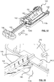
- a syringe driving apparatus 100 includes a housing 110, a driving member 140 coupled to the housing 110, and one or more resilient members, e.g. elastic band(s) 160 connecting the driving member 140 to the housing 110.
- Housing 110 has a front end 102 and a back end 106.
- the front end 102 has a retaining portion 124 configured to receive and fix a flange 84 of a syringe 80 thereto.
- Housing 110 may include an upper portion 110a and a lower portion 110b which is/are generally and interchangeably referred to as housing in the context of this disclosure.
- Driving member 140 has an actuator 142 disposed in the housing 110, a handle 146 disposed outside of the housing 110, and a stem 144 connecting the actuator 142 and the handle 146.
- Stem 144 is positioned to pass through a back opening 109 formed at back end 106 of housing 110.
- Elastic band 160 has two fixing portions 162, 164 and a middle portion 166 between the two fixing portions 162 and 164.
- the two fixing portions 162, 164 are formed by looping the band 160 around the pin like features and fixed to the housing 110, and the middle portion 166 wraps around actuator 142 to urge the actuator 142 towards the front end 102 of housing 110.
- Driving member 140 is movable relative the housing 110 between a first position and a second position. When driving member 140 is at the first position, as shown in Fig. 6 , elastic band 160 is less stretched, to keep the actuator 142 closer to the front end 102 of housing 110. Displacement of the driving member 140 towards the second position, e.g. along direction D1, as shown in Fig.
- driving member 140 is formed of an integral part, by injection molding for example. Between actuator 142 and stem 144 there is formed a neck portion 143.
- Neck portion 143 has a relatively lower strength compared to the actuator 142 and the stem 144, and is configured to present a lower resistance to shear forces and torsional moments.
- neck portion 143 may have a cross sectional dimension less than that of the actuator 142 and the stem 144. As such, neck portion 143 forms a weak, breakable connection, which can be broken by a rotational twisting of the stem 144 relative to the actuator 142.
- a pair of cantilever arms 145 are formed on the stem 144, adjacent to neck portion 143, and projecting slightly away from the stem 144 and towards the actuator 142.
- Cantilever arms 145 are elastically deformable with the free tip 145a flexing relative to the stem 144.
- stem 144 is moved along direction D1 ( Figs. 11 , 12 ) away from housing 110, by e.g. a user gripping the handle 146 to pull the driving member 140 along direction D1, which displaces the actuator 142 away from the front end 102 of the housing 110.
- the stem 144 slides along the back opening 109 formed on the back end 106 of the housing 110.
- the actuator 142 stretches the elastic band 160 due the user's pulling force, resulting in elastic deformation of the elastic band 160 and potential elastic energy stored in the elastic band 160.
- housing 110 may have guide members such as ridge 1122 formed on the inner surface thereof, along axial direction of the housing 110.
- Actuator 142 may have notch 1422 of complementary shape and dimension as the ridge 1122, and engaged to ridge 1122 to assist and guide the displacement of the actuator 142 relative to the housing.
- each cantilever arm 145 When the actuator 142 is displaced to a position closer the back end 106 of the housing 110, the cantilevered arms 145 are caused to flex inwardly towards the stem 144.
- stem 144 Upon the actuator 142 reaching the second position, stem 144 is pulled completely out of the housing 100, and the cantilever arms 145 pass through the back opening 109 and resume the initial shape by flex outwardly away from the stem 114.
- the free end 145a of each cantilever arm 145 are positioned beyond the periphery of the back opening 109 and abut against the housing 110. Stem 144 is therefore prevented from retracting back into the housing 110 by which, the actuator 142 is locked at the second position. Meanwhile, the stretched elastic band 160 exerts a force against the actuator 142 in a direction D2 facing the front end 102 of the housing 110.
- Actuator 142 may have vane 1412 formed adjacent to stem 144 to abut against the housing 110 (110b), to ensure the positioning of actuator 142 when the driving member 140 reaching the second position.
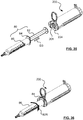
- a syringe 80 which is filled with liquid medication, is attached to the housing 110 with the plunger 82 inserted into the housing 110 through the front opening 101 at the front end 102 of the housing 110, along axial direction D3.
- the generally oval shaped flange 84 of the syringe barrel 86 is rotated to become aligned with the retaining portion 124 surrounding the front opening 101.
- the flange 84 is rotated along circular direction 80R, to position into the groove 124a of the retaining portion 124 to attach the syringe 80 to the apparatus 100.
- the dimension of the housing 110 and the actuator 142 are configured in a manner such that when the portion of the plunger 82 extending out of the barrel 86 is fully received in the housing 110, the end surface 82a of the plunger 82 is in contact with or close proximity to the actuator 142, for example with a gap of about 0 to several mm therebetween.
- Syringe 80 is now ready to be connected to a patient or is already connected, via appropriate tubes/conduits (not shown), for infusion of the medication filled in the syringe 80.
- housing 110 may have ribs 104 formed thereon that engages with the actuator 142 when the actuator 142 is at the second position ( Fig. 17 ) to prevent actuator 142 from rotating during the twisting of the stem 144.
- the actuator 142 Upon the stem 144 and the cantilever arms 145 being broken off from the actuator 142, the actuator 142 is unlocked from the housing 110, allowing the potential energy stored in the elastic band 160 to release which, in turn, brings the actuator 142 into abutment with the plunger 82. Continuous release of the potential energy from the elastic band 160 presses the actuator 142 against the plunger 82. Plunger 82 is then forced to move into the barrel 86 to expel the liquid medication out of the syringe 80 for infusion, as shown in Fig. 21 .
- the plunger of a syringe is pushed by the action of a spiral or clock spring acting on a casing that is an integral part of a driving member e.g. a bobbin assembly installed within a housing of the apparatus.
- the driving member is initially displaced axially along the inner volume space of the housing such that the spiral spring within the casing is winded by the rotation of the casing.
- the driving member includes a slider movably coupled to the casing. The slider has a shaft to which one end of the spiral spring is affixed. Another end of the spiral spring is affixed to the casing.
- the housing has helical grooves formed on the inner surface.
- the casing has ridges formed on the outer surface. The ridges engage with the helical grooves such that linear movement of the casing towards the back end of the housing along the longitudinal axis of the housing rotates to the casing about the longitudinal axis to wind the spiral spring. Unwind of the spiral spring causes the rotational movement of the casing relative to the housing about the longitudinal axis, and brings the casing to move linearly along the axial direction back to the front end of the housing.
- the driving member is initially located at the open end/ front end of the housing and a linear displacement of the driving member towards the opposite, back end of the housing will rotate the casing relative to the housing. Rotation of the casing causes the spring to wind, to store elastic potential energy in the spiral spring..
- the driving member is held at the end of the housing by a release knob that catches on to the stem like protrusion located at the frame of the slider.
- the stem has a neck portion that represents a weak breakable connection, which can be broken by a rotational twisting of the release knob relative to the frame.
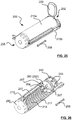
- a syringe driving apparatus 200 includes a housing 210, a driving member or bobbin assembly 220 coupled to the housing 210, and a knob 290 for connecting, locking and releasing the driving member or bobbin assembly 220 to/from the housing 210.
- Housing 210 has a front end 202 and a back end 206.
- the front end 202 has a retaining portion 204 configured to receive and fix a flange 84 of a syringe 80 thereto.
- Housing 210 may include an upper portion 210a and a lower portion 210b which is/are generally and interchangeably referred to as housing in the context of this disclosure.
- Housing 210 may include a movable flap 203 adjacent to the front end 202 to cover the front opening 201 for, e.g. dust-proof purpose.
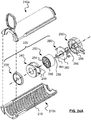
- Driving member or bobbin assembly 220 includes a casing 240, a slider 260 coupled to casing 240, a shaft 266 formed on the slider 260 having a frame 262 engaged to housing 210 and disposed in the casing 240, and a spiral spring 250 disposed in the casing 240.
- Driving member 220 may optionally include a seat plate or disc 230 rotatably attached to the slider 260.
- An inner end 256 of the spiral spring 250 is fixed to the shaft 266, and an outer end 254 of the spiral spring 250 is fixed to the inner slot 246 of the casing 240.
- the knob 290 is attached to the back end 206 of housing 210, and is rotatable relative to housing 210.
- the slider 260 has a stem 264 that has features to enable its fitting with the tubular catch 296 disposed on the inner side of the knob 290. Stem 264 is positioned to pass through a back opening 209 formed at back end 206 of housing 210.
- Apparatus 200 may include a clip 207 formed on the housing 210 for attaching the apparatus 200 to an Intravenous (IV) line so that the apparatus 200 can stay in place before, during and/after the infusion operation.
- Clip 207 may also be used to pinch the IV line if needed during operation.
- Clip 207 may be formed integral to knob 290.
- clip 207 may be formed as an integral to housing 210 or other portion of the apparatus 200, or a separate part assembled to the housing 210 or other parts of the apparatus 200.
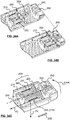
- the housing 210 has one or more helical grooves 218 formed on the inner surface thereof.
- the casing 240 has ridges 248 formed on the outer side surface thereof. Ridges 248 engage the helical grooves 218 to enable simultaneous rotational and axial movement of the casing 240 relative to the housing 210. Due the engagement of the ridges 248 and grooves 218, movement of the casing 240 along axial direction 208 of housing 210 from the front end 202 toward the back end 206 of the housing 210 rotates the casing 240 to wind the spiral spring 250 with respect to a spring axis 258, to store potential energy in the spiral spring 250.
- Neck portion 263 has a relatively lower strength compared to the stem 264 and frame 262, and is configured to present a lower resistance to shear forces and torsional moments.
- neck portion 263 may have a cross sectional dimension less than that of the stem 264. As such, neck portion 263 forms a weak, breakable connection between the frame 262 and the stem 264, which can be broken by a rotational twisting of the stem relative to the frame 262.
- a pair of winglets 261 are formed on the frame 262 and engaged to housing 210, restricting rotational movement of the frame 262 relative to housing 210, hence accentuating the torsional forces on the neck 263 via the stem 264.
- the driving member 220 When the apparatus 200 is at an unused state ( Fig. 27 ), e.g. during the shipment and/or storage period, the driving member 220 may be positioned adjacent to the front end 202 of the housing 210, at which, the spiral spring 250 is at uncoiled or less-coiled state.
- driving member 220 is moved along the axial direction 208 of housing 210 toward the back end 206 of housing 210 ( Fig. 28 ), during which, the casing 240 is rotated to wind the spiral spring 250 to store potential energy in the spiral spring 250.
- the stem 264 is positioned to pass through the back opening 209 of the housing 210, and is inserted into and locked to the knob 290 by the tubular catch 296.
- the peripheral force F1 is converted into an axial force F2 along axial direction 208, to cause displacement of the driving member 220 in the axial direction 208 of the housing 210.
- the axial displacement of the driving member 220 arising from a rotational movement of the casing 240 serves to push the plunger of a syringe attached to the housing 210 for infusion operation, as illustrated in further detail hereinafter.
- Vane 2642 maybe formed adjacent to stem 264 to abut against the housing 210 (210b), to ensure the positioning of slider 260 when reaching the back end 206 of the housing 210.
- a syringe 80 which is fully or partially filled with liquid medication, is attached to the apparatus 200 with the plunger 82 placing through the front opening 201 at the front end 202 of the housing 210, along axial direction D3, and with the plunger 82 brought into abutment with the driving member 220. Further advancement of the plunger 82 along axial direction D3 into the housing 210 presses against the driving member 220, to move the driving member 220 towards the back end 206 of the housing 210, along the axial direction 208 of housing 210.
- the generally oval shaped flange 84 of the syringe barrel 86 is rotated to become aligned with the retaining portion 224 surrounding the front opening 201.
- the flange 84 is rotated along circular direction 80R, to position into the groove 204a of the retaining portion 224 to attach the syringe 80 to the apparatus 200.
- the dimension of the housing 210 and the driving member 220 are configured in a manner such that when the plunger 82 is fully received in the housing 210, the driving member 220 is positioned at the back end 206 of the housing and engaged with the knob 290, and abuts against the plunder 82. Syringe 80 is now ready for infusion operation.
- a user twists (along direction 294R, Fig. 37B ) the knob 290 relative to the housing 210, to break the stem 264 at the neck 263.
- the casing 240, spiral spring 250 and frame 262 are therefore detached from the stem 264.
- the winglets 267 formed at the sides of the frame 262 engages to the slots 217 formed on the housing 210 that cross the grooves 218 of the inner walls of the housing 210, to prevent the frame 262 from rotating during the twisting of the stem 264.
- the casing 260 is unlocked from the housing 210, to allow the potential energy stored in the spiral spring 250 to release, by which, the casing 260 is driven by the spiral spring 250 to push the plunder 82 into the barrel 86 to expel the liquid medicine from the syringe 80 for infusion.
Landscapes
- Health & Medical Sciences (AREA)
- Vascular Medicine (AREA)
- Engineering & Computer Science (AREA)
- Anesthesiology (AREA)
- Biomedical Technology (AREA)
- Heart & Thoracic Surgery (AREA)
- Hematology (AREA)
- Life Sciences & Earth Sciences (AREA)
- Animal Behavior & Ethology (AREA)
- General Health & Medical Sciences (AREA)
- Public Health (AREA)
- Veterinary Medicine (AREA)
- Infusion, Injection, And Reservoir Apparatuses (AREA)
Applications Claiming Priority (2)
| Application Number | Priority Date | Filing Date | Title |
|---|---|---|---|
| US201662437918P | 2016-12-22 | 2016-12-22 | |
| US201762479606P | 2017-03-31 | 2017-03-31 |
Publications (2)
| Publication Number | Publication Date |
|---|---|
| EP3338830A1 true EP3338830A1 (fr) | 2018-06-27 |
| EP3338830B1 EP3338830B1 (fr) | 2020-02-12 |
Family
ID=60782005
Family Applications (1)
| Application Number | Title | Priority Date | Filing Date |
|---|---|---|---|
| EP17209918.6A Active EP3338830B1 (fr) | 2016-12-22 | 2017-12-22 | Appareil d'entraînement de seringue |
Country Status (3)
| Country | Link |
|---|---|
| US (1) | US10946146B2 (fr) |
| EP (1) | EP3338830B1 (fr) |
| CN (1) | CN108379698B (fr) |
Families Citing this family (3)
| Publication number | Priority date | Publication date | Assignee | Title |
|---|---|---|---|---|
| AU2019100169A4 (en) | 2019-02-15 | 2019-03-28 | Multigate Medical Products Pty Ltd | A Clip |
| CN110215570A (zh) * | 2019-04-19 | 2019-09-10 | 吴银洪 | 具有互斥张力稳定的全自动固体传感器体内注射器 |
| CN115887826B (zh) * | 2022-07-19 | 2025-10-24 | 浙江森迈合创医疗科技有限公司 | 自动注射装置 |
Citations (4)
| Publication number | Priority date | Publication date | Assignee | Title |
|---|---|---|---|---|
| US5318539A (en) * | 1986-10-17 | 1994-06-07 | Alexander G. B. O'Neil | Liquid feeding apparatus utilizing capillary tubing, and syringe driver |
| EP2898910A1 (fr) * | 2014-01-24 | 2015-07-29 | Freddie Eng Hwee Lee | appareil de distribution de fluide alimenté par bande élastique |
| WO2015166286A2 (fr) * | 2014-05-01 | 2015-11-05 | New Injection Systems Ltd | Indicateur |
| EP3281659A1 (fr) * | 2016-05-30 | 2018-02-14 | Epic Medical Pte Ltd | Appareil et système de distribution de fluides |
Family Cites Families (5)
| Publication number | Priority date | Publication date | Assignee | Title |
|---|---|---|---|---|
| US20120330275A1 (en) * | 2011-06-23 | 2012-12-27 | Medinvention LLC | Syringe Evacuator |
| EP2703022A1 (fr) * | 2012-09-03 | 2014-03-05 | LTS LOHMANN Therapie-Systeme AG | Injecteur à usage unique avec déclenchement en deux étapes |
| US20150005708A1 (en) * | 2013-06-28 | 2015-01-01 | Juvaplus Sa | Injection device |
| RU2016124541A (ru) * | 2013-11-22 | 2017-12-27 | Санофи-Авентис Дойчланд Гмбх | Устройство с пружинным механизмом для доставки лекарственного средства |
| US10029048B2 (en) * | 2014-05-13 | 2018-07-24 | Allergan, Inc. | High force injection devices |
-
2017
- 2017-12-20 US US15/848,528 patent/US10946146B2/en active Active
- 2017-12-22 EP EP17209918.6A patent/EP3338830B1/fr active Active
- 2017-12-22 CN CN201711407605.2A patent/CN108379698B/zh not_active Expired - Fee Related
Patent Citations (4)
| Publication number | Priority date | Publication date | Assignee | Title |
|---|---|---|---|---|
| US5318539A (en) * | 1986-10-17 | 1994-06-07 | Alexander G. B. O'Neil | Liquid feeding apparatus utilizing capillary tubing, and syringe driver |
| EP2898910A1 (fr) * | 2014-01-24 | 2015-07-29 | Freddie Eng Hwee Lee | appareil de distribution de fluide alimenté par bande élastique |
| WO2015166286A2 (fr) * | 2014-05-01 | 2015-11-05 | New Injection Systems Ltd | Indicateur |
| EP3281659A1 (fr) * | 2016-05-30 | 2018-02-14 | Epic Medical Pte Ltd | Appareil et système de distribution de fluides |
Also Published As
| Publication number | Publication date |
|---|---|
| EP3338830B1 (fr) | 2020-02-12 |
| CN108379698B (zh) | 2022-01-04 |
| US10946146B2 (en) | 2021-03-16 |
| US20180177954A1 (en) | 2018-06-28 |
| CN108379698A (zh) | 2018-08-10 |
Similar Documents
| Publication | Publication Date | Title |
|---|---|---|
| CN109689131B (zh) | 药剂递送设备 | |
| JP4934841B2 (ja) | 針挿入を伴う自動注射装置 | |
| TWI646991B (zh) | 驅動控制機構及用於可注射匣之自動注射器 | |
| US9623192B2 (en) | Safety shield system for a single use flexible-type compression syringe, and injection device | |
| CN103764206B (zh) | 用于肾上腺素注射的自动注射器 | |
| CN103068424B (zh) | 用于预装式注射器的安全装置和注射装置 | |
| CN103732275B (zh) | 注射设备 | |
| EP3310413B1 (fr) | Dispositif d'administration de médicament | |
| US10632248B2 (en) | Medicament delivery device | |
| US10709841B2 (en) | Injection device | |
| TW200306873A (en) | Collapsible syringe cartridge | |
| HUP0200877A2 (en) | Self-injection device and method for its operation | |
| CN110559523A (zh) | 安全注射器 | |
| JP2016533800A (ja) | 携帯型注入ポンプ | |
| US10946146B2 (en) | Syringe driving apparatus and system | |
| US20200114068A1 (en) | Injector device | |
| CN119997995A (zh) | 用于手动和自动注射设备注射装置的动力辅助 | |
| WO2018166701A1 (fr) | Dispositif injecteur |
Legal Events
| Date | Code | Title | Description |
|---|---|---|---|
| PUAI | Public reference made under article 153(3) epc to a published international application that has entered the european phase |
Free format text: ORIGINAL CODE: 0009012 |
|
| STAA | Information on the status of an ep patent application or granted ep patent |
Free format text: STATUS: THE APPLICATION HAS BEEN PUBLISHED |
|
| AK | Designated contracting states |
Kind code of ref document: A1 Designated state(s): AL AT BE BG CH CY CZ DE DK EE ES FI FR GB GR HR HU IE IS IT LI LT LU LV MC MK MT NL NO PL PT RO RS SE SI SK SM TR |
|
| AX | Request for extension of the european patent |
Extension state: BA ME |
|
| STAA | Information on the status of an ep patent application or granted ep patent |
Free format text: STATUS: REQUEST FOR EXAMINATION WAS MADE |
|
| 17P | Request for examination filed |
Effective date: 20181226 |
|
| RBV | Designated contracting states (corrected) |
Designated state(s): AL AT BE BG CH CY CZ DE DK EE ES FI FR GB GR HR HU IE IS IT LI LT LU LV MC MK MT NL NO PL PT RO RS SE SI SK SM TR |
|
| GRAP | Despatch of communication of intention to grant a patent |
Free format text: ORIGINAL CODE: EPIDOSNIGR1 |
|
| STAA | Information on the status of an ep patent application or granted ep patent |
Free format text: STATUS: GRANT OF PATENT IS INTENDED |
|
| RIC1 | Information provided on ipc code assigned before grant |
Ipc: A61M 5/145 20060101AFI20190731BHEP |
|
| INTG | Intention to grant announced |
Effective date: 20190822 |
|
| RIN1 | Information on inventor provided before grant (corrected) |
Inventor name: LEE, ENG HWEE, FREDDIE |
|
| GRAS | Grant fee paid |
Free format text: ORIGINAL CODE: EPIDOSNIGR3 |
|
| GRAA | (expected) grant |
Free format text: ORIGINAL CODE: 0009210 |
|
| STAA | Information on the status of an ep patent application or granted ep patent |
Free format text: STATUS: THE PATENT HAS BEEN GRANTED |
|
| AK | Designated contracting states |
Kind code of ref document: B1 Designated state(s): AL AT BE BG CH CY CZ DE DK EE ES FI FR GB GR HR HU IE IS IT LI LT LU LV MC MK MT NL NO PL PT RO RS SE SI SK SM TR |
|
| REG | Reference to a national code |
Ref country code: GB Ref legal event code: FG4D |
|
| REG | Reference to a national code |
Ref country code: CH Ref legal event code: EP |
|
| REG | Reference to a national code |
Ref country code: AT Ref legal event code: REF Ref document number: 1231248 Country of ref document: AT Kind code of ref document: T Effective date: 20200215 |
|
| REG | Reference to a national code |
Ref country code: IE Ref legal event code: FG4D |
|
| REG | Reference to a national code |
Ref country code: DE Ref legal event code: R096 Ref document number: 602017011607 Country of ref document: DE |
|
| RAP2 | Party data changed (patent owner data changed or rights of a patent transferred) |
Owner name: EPIC MEDICAL PTE LTD |
|
| PG25 | Lapsed in a contracting state [announced via postgrant information from national office to epo] |
Ref country code: RS Free format text: LAPSE BECAUSE OF FAILURE TO SUBMIT A TRANSLATION OF THE DESCRIPTION OR TO PAY THE FEE WITHIN THE PRESCRIBED TIME-LIMIT Effective date: 20200212 Ref country code: NO Free format text: LAPSE BECAUSE OF FAILURE TO SUBMIT A TRANSLATION OF THE DESCRIPTION OR TO PAY THE FEE WITHIN THE PRESCRIBED TIME-LIMIT Effective date: 20200512 Ref country code: FI Free format text: LAPSE BECAUSE OF FAILURE TO SUBMIT A TRANSLATION OF THE DESCRIPTION OR TO PAY THE FEE WITHIN THE PRESCRIBED TIME-LIMIT Effective date: 20200212 |
|
| REG | Reference to a national code |
Ref country code: LT Ref legal event code: MG4D |
|
| REG | Reference to a national code |
Ref country code: NL Ref legal event code: MP Effective date: 20200212 |
|
| PG25 | Lapsed in a contracting state [announced via postgrant information from national office to epo] |
Ref country code: IS Free format text: LAPSE BECAUSE OF FAILURE TO SUBMIT A TRANSLATION OF THE DESCRIPTION OR TO PAY THE FEE WITHIN THE PRESCRIBED TIME-LIMIT Effective date: 20200612 Ref country code: BG Free format text: LAPSE BECAUSE OF FAILURE TO SUBMIT A TRANSLATION OF THE DESCRIPTION OR TO PAY THE FEE WITHIN THE PRESCRIBED TIME-LIMIT Effective date: 20200512 Ref country code: HR Free format text: LAPSE BECAUSE OF FAILURE TO SUBMIT A TRANSLATION OF THE DESCRIPTION OR TO PAY THE FEE WITHIN THE PRESCRIBED TIME-LIMIT Effective date: 20200212 Ref country code: GR Free format text: LAPSE BECAUSE OF FAILURE TO SUBMIT A TRANSLATION OF THE DESCRIPTION OR TO PAY THE FEE WITHIN THE PRESCRIBED TIME-LIMIT Effective date: 20200513 Ref country code: LV Free format text: LAPSE BECAUSE OF FAILURE TO SUBMIT A TRANSLATION OF THE DESCRIPTION OR TO PAY THE FEE WITHIN THE PRESCRIBED TIME-LIMIT Effective date: 20200212 Ref country code: SE Free format text: LAPSE BECAUSE OF FAILURE TO SUBMIT A TRANSLATION OF THE DESCRIPTION OR TO PAY THE FEE WITHIN THE PRESCRIBED TIME-LIMIT Effective date: 20200212 |
|
| PG25 | Lapsed in a contracting state [announced via postgrant information from national office to epo] |
Ref country code: NL Free format text: LAPSE BECAUSE OF FAILURE TO SUBMIT A TRANSLATION OF THE DESCRIPTION OR TO PAY THE FEE WITHIN THE PRESCRIBED TIME-LIMIT Effective date: 20200212 |
|
| PG25 | Lapsed in a contracting state [announced via postgrant information from national office to epo] |
Ref country code: PT Free format text: LAPSE BECAUSE OF FAILURE TO SUBMIT A TRANSLATION OF THE DESCRIPTION OR TO PAY THE FEE WITHIN THE PRESCRIBED TIME-LIMIT Effective date: 20200705 Ref country code: DK Free format text: LAPSE BECAUSE OF FAILURE TO SUBMIT A TRANSLATION OF THE DESCRIPTION OR TO PAY THE FEE WITHIN THE PRESCRIBED TIME-LIMIT Effective date: 20200212 Ref country code: ES Free format text: LAPSE BECAUSE OF FAILURE TO SUBMIT A TRANSLATION OF THE DESCRIPTION OR TO PAY THE FEE WITHIN THE PRESCRIBED TIME-LIMIT Effective date: 20200212 Ref country code: EE Free format text: LAPSE BECAUSE OF FAILURE TO SUBMIT A TRANSLATION OF THE DESCRIPTION OR TO PAY THE FEE WITHIN THE PRESCRIBED TIME-LIMIT Effective date: 20200212 Ref country code: SM Free format text: LAPSE BECAUSE OF FAILURE TO SUBMIT A TRANSLATION OF THE DESCRIPTION OR TO PAY THE FEE WITHIN THE PRESCRIBED TIME-LIMIT Effective date: 20200212 Ref country code: RO Free format text: LAPSE BECAUSE OF FAILURE TO SUBMIT A TRANSLATION OF THE DESCRIPTION OR TO PAY THE FEE WITHIN THE PRESCRIBED TIME-LIMIT Effective date: 20200212 Ref country code: SK Free format text: LAPSE BECAUSE OF FAILURE TO SUBMIT A TRANSLATION OF THE DESCRIPTION OR TO PAY THE FEE WITHIN THE PRESCRIBED TIME-LIMIT Effective date: 20200212 Ref country code: CZ Free format text: LAPSE BECAUSE OF FAILURE TO SUBMIT A TRANSLATION OF THE DESCRIPTION OR TO PAY THE FEE WITHIN THE PRESCRIBED TIME-LIMIT Effective date: 20200212 Ref country code: LT Free format text: LAPSE BECAUSE OF FAILURE TO SUBMIT A TRANSLATION OF THE DESCRIPTION OR TO PAY THE FEE WITHIN THE PRESCRIBED TIME-LIMIT Effective date: 20200212 |
|
| REG | Reference to a national code |
Ref country code: DE Ref legal event code: R097 Ref document number: 602017011607 Country of ref document: DE |
|
| REG | Reference to a national code |
Ref country code: AT Ref legal event code: MK05 Ref document number: 1231248 Country of ref document: AT Kind code of ref document: T Effective date: 20200212 |
|
| PLBE | No opposition filed within time limit |
Free format text: ORIGINAL CODE: 0009261 |
|
| STAA | Information on the status of an ep patent application or granted ep patent |
Free format text: STATUS: NO OPPOSITION FILED WITHIN TIME LIMIT |
|
| 26N | No opposition filed |
Effective date: 20201113 |
|
| PG25 | Lapsed in a contracting state [announced via postgrant information from national office to epo] |
Ref country code: IT Free format text: LAPSE BECAUSE OF FAILURE TO SUBMIT A TRANSLATION OF THE DESCRIPTION OR TO PAY THE FEE WITHIN THE PRESCRIBED TIME-LIMIT Effective date: 20200212 Ref country code: AT Free format text: LAPSE BECAUSE OF FAILURE TO SUBMIT A TRANSLATION OF THE DESCRIPTION OR TO PAY THE FEE WITHIN THE PRESCRIBED TIME-LIMIT Effective date: 20200212 |
|
| PG25 | Lapsed in a contracting state [announced via postgrant information from national office to epo] |
Ref country code: PL Free format text: LAPSE BECAUSE OF FAILURE TO SUBMIT A TRANSLATION OF THE DESCRIPTION OR TO PAY THE FEE WITHIN THE PRESCRIBED TIME-LIMIT Effective date: 20200212 Ref country code: SI Free format text: LAPSE BECAUSE OF FAILURE TO SUBMIT A TRANSLATION OF THE DESCRIPTION OR TO PAY THE FEE WITHIN THE PRESCRIBED TIME-LIMIT Effective date: 20200212 |
|
| PG25 | Lapsed in a contracting state [announced via postgrant information from national office to epo] |
Ref country code: MC Free format text: LAPSE BECAUSE OF FAILURE TO SUBMIT A TRANSLATION OF THE DESCRIPTION OR TO PAY THE FEE WITHIN THE PRESCRIBED TIME-LIMIT Effective date: 20200212 |
|
| PG25 | Lapsed in a contracting state [announced via postgrant information from national office to epo] |
Ref country code: LU Free format text: LAPSE BECAUSE OF NON-PAYMENT OF DUE FEES Effective date: 20201222 |
|
| PG25 | Lapsed in a contracting state [announced via postgrant information from national office to epo] |
Ref country code: TR Free format text: LAPSE BECAUSE OF FAILURE TO SUBMIT A TRANSLATION OF THE DESCRIPTION OR TO PAY THE FEE WITHIN THE PRESCRIBED TIME-LIMIT Effective date: 20200212 Ref country code: MT Free format text: LAPSE BECAUSE OF FAILURE TO SUBMIT A TRANSLATION OF THE DESCRIPTION OR TO PAY THE FEE WITHIN THE PRESCRIBED TIME-LIMIT Effective date: 20200212 Ref country code: CY Free format text: LAPSE BECAUSE OF FAILURE TO SUBMIT A TRANSLATION OF THE DESCRIPTION OR TO PAY THE FEE WITHIN THE PRESCRIBED TIME-LIMIT Effective date: 20200212 |
|
| PG25 | Lapsed in a contracting state [announced via postgrant information from national office to epo] |
Ref country code: MK Free format text: LAPSE BECAUSE OF FAILURE TO SUBMIT A TRANSLATION OF THE DESCRIPTION OR TO PAY THE FEE WITHIN THE PRESCRIBED TIME-LIMIT Effective date: 20200212 Ref country code: AL Free format text: LAPSE BECAUSE OF FAILURE TO SUBMIT A TRANSLATION OF THE DESCRIPTION OR TO PAY THE FEE WITHIN THE PRESCRIBED TIME-LIMIT Effective date: 20200212 |
|
| PGFP | Annual fee paid to national office [announced via postgrant information from national office to epo] |
Ref country code: IE Payment date: 20231217 Year of fee payment: 7 |
|
| PGFP | Annual fee paid to national office [announced via postgrant information from national office to epo] |
Ref country code: BE Payment date: 20231218 Year of fee payment: 7 |
|
| PGFP | Annual fee paid to national office [announced via postgrant information from national office to epo] |
Ref country code: CH Payment date: 20240101 Year of fee payment: 7 |
|
| PGFP | Annual fee paid to national office [announced via postgrant information from national office to epo] |
Ref country code: GB Payment date: 20241223 Year of fee payment: 8 |
|
| PGFP | Annual fee paid to national office [announced via postgrant information from national office to epo] |
Ref country code: FR Payment date: 20241223 Year of fee payment: 8 |
|
| PGFP | Annual fee paid to national office [announced via postgrant information from national office to epo] |
Ref country code: DE Payment date: 20241230 Year of fee payment: 8 |
|
| REG | Reference to a national code |
Ref country code: CH Ref legal event code: PL |
|
| REG | Reference to a national code |
Ref country code: BE Ref legal event code: MM Effective date: 20241231 |
|
| PG25 | Lapsed in a contracting state [announced via postgrant information from national office to epo] |
Ref country code: BE Free format text: LAPSE BECAUSE OF NON-PAYMENT OF DUE FEES Effective date: 20241231 |
|
| PG25 | Lapsed in a contracting state [announced via postgrant information from national office to epo] |
Ref country code: CH Free format text: LAPSE BECAUSE OF NON-PAYMENT OF DUE FEES Effective date: 20241231 |
|
| PG25 | Lapsed in a contracting state [announced via postgrant information from national office to epo] |
Ref country code: IE Free format text: LAPSE BECAUSE OF NON-PAYMENT OF DUE FEES Effective date: 20241222 |