EP3338904A1 - Filière et son procédé de fabrication - Google Patents
Filière et son procédé de fabrication Download PDFInfo
- Publication number
- EP3338904A1 EP3338904A1 EP17203229.4A EP17203229A EP3338904A1 EP 3338904 A1 EP3338904 A1 EP 3338904A1 EP 17203229 A EP17203229 A EP 17203229A EP 3338904 A1 EP3338904 A1 EP 3338904A1
- Authority
- EP
- European Patent Office
- Prior art keywords
- nozzle
- sectors
- wire
- nozzle according
- longitudinal axis
- Prior art date
- Legal status (The legal status is an assumption and is not a legal conclusion. Google has not performed a legal analysis and makes no representation as to the accuracy of the status listed.)
- Withdrawn
Links
Images


Classifications
-
- B—PERFORMING OPERATIONS; TRANSPORTING
- B21—MECHANICAL METAL-WORKING WITHOUT ESSENTIALLY REMOVING MATERIAL; PUNCHING METAL
- B21C—MANUFACTURE OF METAL SHEETS, WIRE, RODS, TUBES, PROFILES OR LIKE SEMI-MANUFACTURED PRODUCTS OTHERWISE THAN BY ROLLING; AUXILIARY OPERATIONS USED IN CONNECTION WITH METAL-WORKING WITHOUT ESSENTIALLY REMOVING MATERIAL
- B21C1/00—Manufacture of metal sheets, wire, rods, tubes or like semi-manufactured products by drawing
- B21C1/02—Drawing metal wire or like flexible metallic material by drawing machines or apparatus in which the drawing action is effected by drums
-
- B—PERFORMING OPERATIONS; TRANSPORTING
- B21—MECHANICAL METAL-WORKING WITHOUT ESSENTIALLY REMOVING MATERIAL; PUNCHING METAL
- B21C—MANUFACTURE OF METAL SHEETS, WIRE, RODS, TUBES, PROFILES OR LIKE SEMI-MANUFACTURED PRODUCTS OTHERWISE THAN BY ROLLING; AUXILIARY OPERATIONS USED IN CONNECTION WITH METAL-WORKING WITHOUT ESSENTIALLY REMOVING MATERIAL
- B21C3/00—Profiling tools for metal drawing; Combinations of dies and mandrels for metal drawing
- B21C3/02—Dies; Selection of material therefor; Cleaning thereof
- B21C3/12—Die holders; Rotating dies
- B21C3/14—Die holders combined with devices for guiding the drawing material or combined with devices for cooling, heating, or lubricating
Definitions
- the invention relates to a nozzle for drawing wire or for coating wires or fibers, a method for producing a nozzle and a use of such a nozzle, wherein the nozzle is formed of hard metal and having a draw hole with a longitudinal axis, wherein the draw hole a funnel-shaped Inlet zone and a forming zone with a pull handle forms.
- Such nozzles are well known and are regularly used for pulling wire or metal wire.
- these nozzles can also be used for coating wires or fibers.
- the wire or fiber may be coated with a relatively uniform lacquer coating.
- the wire or fiber then has a smaller diameter than a pull of the nozzle.
- Dies used in this way can also be referred to as a die.
- Dies for drawing or forming or painting wire may be made of hardened steel, natural diamond, synthetic diamond (SCD, PKC, PCD) or cemented carbide.
- Carbide is a Sintered material of a mixture of predominantly tungsten carbide with cobalt.
- a disadvantage of drawing or coating wires or fibers is that the respective wire or fiber has to be threaded into the nozzle.
- Drawing or painting regularly also have a plurality of nozzles with which a corresponding number of wires or fibers are treated or processed. So it is then relatively time-consuming to thread the possibly very thin wires or fibers in the respective nozzles when the drawing device or painting device is equipped with a production lot or threading in the context of troubleshooting or replacement of a nozzle is required. These setup times always affect the manufacturing costs for wires or fibers.
- a nozzle having the features of claim 1 a treatment apparatus having the features of claim 17, a method having the features of claim 19 and a use of a nozzle having the features of claim 20.
- the nozzle according to the invention for drawing wire or for coating wires or fibers is formed of hard metal and has a draw hole with a longitudinal axis, wherein the draw hole forms a funnel-shaped inlet zone and a forming zone with a pull handle, wherein the nozzle relative to the longitudinal axis of at least two sectors is formed in several parts.
- the nozzle is formed so divisible with respect to the longitudinal axis of the draw hole, that the two hard metal sectors can preferably be completely separated from each other. It is therefore no longer necessary to thread a wire or a fiber into the nozzle or the draw hole. Rather, a wire or fiber that passes through a puller or paint applicator can be easily positioned within the nozzle. At this time, the sectors of the nozzle can be separated from each other and put back together around the wire or the fiber, so that the nozzle is formed by the sectors. The then juxtaposed or joined together sectors form the draw hole, through which the wire or the fiber passes. The wire or fiber is therefore only inserted into the draw hole, whereby a substantial time advantage over threading the wire or fiber into the nozzle can be achieved.
- a sector is understood here as a segment that does not necessarily have to be formed as a circular sector.
- the sector may be formed as a segment of the nozzle.
- the sectors may form at least two nozzle halves.
- the nozzle may then be divided in half along the longitudinal axis.
- the nozzle has more than two sectors, so that the nozzle then, for example, three or more sectors, which may be the same or different sizes, may be formed.
- a dividing plane or contact plane of the nozzle can run through the longitudinal axis of the draw hole.
- the nozzle can then be divided in the dividing plane or the respective sectors can then abut each other directly in the dividing plane.
- the dividing plane extends longitudinally along the longitudinal axis of the draw hole. In the transverse direction, the dividing plane also extends through the longitudinal axis, but may also be inclined, for example when one sector forms a larger section of the nozzle than another sector.
- the sectors can be designed as circular ring sectors.
- An inner circle may then be formed from the draw hole and an outer circle of the annulus may be formed from an outer surface of the nozzle.
- the nozzle may be symmetrical with respect to the longitudinal axis, preferably rotationally symmetrical.
- a rotationally symmetrical and thus round in a cross-section nozzle can be produced by simple means.
- the nozzle may be formed with respect to the longitudinal axis with a rotationally symmetrical drawing bore and a polygonal outer contour.
- the polygonal outer contour may in turn be formed symmetrically relative to the longitudinal axis.
- the outer contour relative to a cross section of the nozzle may also be square or rectangular and in principle form any desired shape.
- the outer contour may be square or sections square, such that at least partially straight outer surfaces are formed. Otherwise existing corners of such a contour relative to a cross section of the nozzle may be rounded or have a fiber. Also, first, a round nozzle can be formed, are formed on the parallel straight outer surfaces.
- the draw hole of the nozzle can form a discharge funnel, which is arranged opposite the inlet zone.
- the discharge hopper may preferably be formed on the nozzle when it is used for drawing or forming wire.
- the nozzle may be formed without a discharge funnel.
- the forming zone has a drawing cone.
- the forming zone can then have the drawing cone and the drawing pick.
- the drawbar can serve for forming a wire or for centering a wire during coating. Also, the drawbar may be formed with a radius.
- the nozzle may include a clamping device that can receive and clamp the sectors.
- the clamping device may be any device which is suitable to position the sectors of the nozzle relative to each other and to press against each other, that the draw hole is formed and a wire or a fiber can be pulled through the draw hole therethrough.
- the clamping device can then be designed so that, for example, occurring during a forming of a wire in the draw hole forces, in particular radial forces can be absorbed by the clamping device.
- the clamping device may be polygonal or circular and form a through hole in which the sectors may be received. An inner contour of the passage opening can then at least in sections to an outer contour of the sectors be adjusted.
- the clamping device may be formed as an annular sleeve.
- the passage opening can also be square or rectangular, if the sectors at least partially form parallel outer surfaces.
- the passage opening and / or the sectors are conical at least in sections.
- a conical design is understood to mean an inclination of the outer surfaces in the direction of the longitudinal axis. So it is particularly easy to introduce the sectors together in the through hole and clamp it.
- an outer surface of the sectors may be formed together in a frusto-conical shape, in which case an inner surface of the passage opening may be formed coincidentally.
- the clamping device may have a longitudinal slot which is so wide that a wire or a fiber, which can be pulled or coated by means of the nozzle, can be inserted through the longitudinal slot into the passage opening.
- the longitudinal slot can then also be designed to extend in the direction of the longitudinal axis in the clamping device. If the clamping device is designed, for example, annular, the longitudinal slot may be formed in the manner of a circular ring cutout. After the sectors of the nozzle are arranged around the wire or fiber, the clamping device can then be slipped onto the wire or fiber over the longitudinal slot and pushed onto the sectors.
- the longitudinal slot can also run transversely to the longitudinal axis, as long as the wire or the fiber can be introduced via the longitudinal slot into the passage opening of the clamping device.
- a width of the longitudinal slot may be so large that it substantially corresponds to a diameter of the wire or the fiber, but is preferably larger.
- the drawing handle may have a diameter D of 0.1 to 3.0 mm, preferably 0.1 to 2.0 mm, particularly preferably 0.1 to 0.5 mm. Then it becomes possible to produce particularly thin wires by forming or to coat thin wires or fibers with, for example, a lacquer layer.
- the wire having a starting diameter larger than a diameter D of the drawing hole is drawn through the nozzle to obtain a final diameter D E substantially equal to the diameter D of the drawing hole or slightly larger due to widening of the wire is smaller than a diameter D of the drawing hole, and a final diameter D E is greater than the initial diameter, because coating material such as paint has been applied to the wire or fiber.
- the drawing handle may have a diameter D and a length L H , wherein these may be formed in a ratio of L H to D ⁇ 1 to 10, preferably from Lli to D ⁇ 5 to 10, preferably from L H to D ⁇ 10 , By a comparatively long drawing a particularly dimensionally stable deformation or uniform coating of a wire or a fiber is possible.
- a surface of the sectors may be at least partially, preferably completely coated with an amorphous carbon layer, wherein the amorphous carbon layer may be applied by a DLC coating process.
- the amorphous carbon layer or coating may have a smooth surface with high abrasion resistance.
- such a coating may have a hardness of about 2,500 to 3,000 HV.
- the coating has a black color, so that any damage or wear of the coating can be easily detected.
- the coating of the surface of the drawing hole with amorphous carbon is inexpensive to produce, since a plurality of nozzles or sectors can be coated simultaneously. It is already sufficient if the amorphous carbon layer completely covers at least the surface of the drawing handle, so that rapid wear of the drawing handle can be prevented. However, it is particularly difficult to completely form an amorphous carbon coating on the surface of the drawholes, if it has a comparatively small diameter D and / or a comparatively long length L H.
- the amorphous carbon layer may be applied by a DLC (Diamond Like Carbon) coating process.
- a diamond-like carbon can be deposited on the surface of the draw hole.
- Such a coating is temperature stable up to 400 ° C or 600 ° C, so that heating of the nozzle as a result of a drawing or coating process can hardly damage the amorphous carbon layer.
- a particularly smooth surface can be obtained by the coating, whereby a friction coefficient can be advantageously reduced.
- a surface of a wire or a fiber can be made particularly smooth by means of the nozzle.
- the surface may be coated with an amorphous carbon layer of at least 5 ⁇ m thick, preferably at least 3 ⁇ m thick, more preferably at least 1 ⁇ m ⁇ 0.5 ⁇ m thick.
- a carbon layer of this thickness is sufficiently strong and resistant to eventual wear when used as intended. In particular, even with such layer thicknesses, a substantial extension of a service life can be achieved.
- the layer thickness can be formed independently of a surface contour. It is also possible to take into account the thickness of the carbon layer during a machining of the draw hole.
- the surface may comprise a hydrogen-free amorphous carbon layer, with a tetrahedral hydrogen-free amorphous carbon layer, with a metal-containing hydrogen-free amorphous carbon layer, with a hydrogen-containing amorphous carbon layer with a hydrogen content of> 35%, with a tetrahedral hydrogen-containing amorphous carbon layer with a hydrogen content of> 25%, with a metal-containing hydrogen-containing amorphous carbon layer or with a modified, be coated with at least one of silicon, oxygen, nitrogen, fluorine and / or boron-bonded hydrogen-containing amorphous carbon layer. Due to their bonding structure, such carbon layers are essentially equivalent to a diamond layer.
- a carbon layer can be formed, which has a particularly high wear resistance and a low coefficient of friction.
- a doping of the amorphous carbon layer with at least one of the elements silicon, oxygen, nitrogen, fluorine and boron makes it possible to significantly influence the properties of the carbon layer. For example, a temperature resistance in an oxygen-containing environment can be increased by means of silicon.
- the treatment device according to the invention in particular drawing device or painting device, has a holding device and at least one nozzle, wherein the nozzle is inserted into the holding device, wherein the nozzle is a nozzle according to the invention.
- a plurality of nozzles for example arranged in a row arrangement, can also be arranged on the holding device.
- the holding device can therefore hold the nozzles and position relative to each other on the drawing or painting.
- the holding device may be a plate, for example a Be metal plate within which at least one or preferably a plurality of through holes or holes are formed.
- a nozzle at least one nozzle according to the invention can then be inserted in these further passage openings. Accordingly, the further passage opening for holding the nozzle can also form a clamping device for the sectors of the nozzle.
- the holding device When the holding device is formed as a further passage opening in a body or a plate, the body may have a further longitudinal slot which is so wide that a wire or a fiber which can be pulled or coated by means of the nozzle the further longitudinal slot in the further passage opening can be inserted. An insertability of the wire or the fiber into the nozzle is then not limited by the holding device.
- the nozzle is made of hard metal, wherein the nozzle is formed of at least two sectors in several parts, wherein the sectors in a parting plane of the nozzle with their surfaces together adjacent to be positioned relative to each other, wherein a drawing hole, which runs through the parting plane is formed by eroding.
- a nozzle for drawing or coating wires or fibers is used, wherein the nozzle is made of hard metal, wherein two sectors of the nozzle are arranged around a wire or a fiber, wherein subsequently a clamping device of the nozzle onto the wire or the fiber attached and pushed onto the sectors, wherein the sectors are fixed relative to each other.
- FIG. 1 to 4 shows a nozzle 10 or a die for drawing wire or for coating wires or fibers.
- the nozzle 10 is formed of hard metal and has a draw hole 11 with a longitudinal axis 12 and a funnel-shaped inlet zone 13 and a forming zone 14.
- a pull handle 15 of the forming zone 14 is formed comparatively small here.
- the funnel-shaped inlet zone 13 has an opening angle ⁇ , which is comparatively greater than an opening angle ⁇ of the deformation zone 14.
- the nozzle 10 is formed relative to the longitudinal axis 12 of at least two sectors 16 and 17 in several parts.
- the sectors 16 and 17 are made of hard metal and form nozzle halves 18 and 19, the dividing plane 20 extends straight through the longitudinal axis 12.
- the sectors 16 and 17 are formed coincidentally and symmetrically.
- the draw hole 11 is formed by means of an erosion method in which surfaces 21 and 22 of the sectors 16 and 17 are positioned adjacent to each other in the parting plane 20, so that the draw hole 11 can be formed completely round.
- it may be provided to coat the nozzle 10 or the sectors 16 and 17 with an amorphous carbon layer.
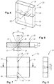
- a synopsis of Fig. 5 to 8 shows a nozzle 23, in contrast to the nozzle of the Fig. 1 to 4 a draw hole 24 having a longitudinal axis 25 and an inlet zone 26, a forming zone 27 and a pull handle 28 has.
- a diameter D of the pull handle 28 essentially determines a final diameter of a wire or a fiber, not shown here.
- the forming zone 27 accordingly has the pull handle 28 with a length L H and a pull cone 30 with a length L K.
- Carbide-made sectors 31 and 32 of the nozzle 23 form nozzle halves 33 and 34, respectively.
- a dividing plane 35 also extends through the longitudinal axis 25, wherein a dividing seam 36 of the sectors 31 and 32 with a jump 37 does not extend in sections in the dividing plane 35.
- At the sector 31 are thus paragraphs 38 and at the sector 32 recesses 39 in accordance with the paragraphs 38th educated. Thus, accidental shifting of the sectors 31 and 32 in the parting plane 35 can be effectively prevented.
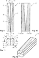
- FIG. 9 to 15 shows a nozzle 40 with a pull hole 41 and the longitudinal axis 42.
- the draw hole 41 is formed as a conical recess 43, which simultaneously forms an inlet zone 44, a forming zone 45 and a drawing handle 46.
- the nozzle 40 comprises three cemented carbide sectors 47 and 48 and a clamping device 50 formed as a circular ring 49.
- Outer surfaces 51 and 52 of the sectors 47 and 48 have straight sections 53 which are parallel relative to the longitudinal axis 42 and tapered sections 54 on the longitudinal axis 42, on.
- the conical sections 54 are inclined by a cone angle ⁇ relative to the longitudinal axis 42.
- the circular ring 49 forms a passage opening 55, the inner surface 56 is also conical and inclined by the cone angle ⁇ relative to a longitudinal axis 57 of the annulus 49.
- the longitudinal axis 57 corresponds in the installation position of the circular ring 49 of the longitudinal axis 42 of the draw hole 41.
- a longitudinal slot 58 is formed through which a wire or a fiber can be passed.
- a radius 59 is formed on an outer edge 60 of the circular ring 49.
- the annulus 49 may now be slid over the sectors 47 and 48 so that the inner surface 56 abuts the portions 54 of the sectors 47 and 48 and the sectors 47 and 48 jam against each other.
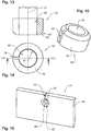
- the Fig. 16 shows a holding device 61, which is formed as a plate 62 with a through hole 63 and a longitudinal slot 64, which opens in the through hole 63 is formed.
- the longitudinal slot 64 is formed so large that a wire or a fiber can be passed through the longitudinal slot 64 into the through hole 63.
- An inner edge 65 of the passage opening 63 is formed with a radius 66.
- the radius 66 as well as the longitudinal slot 64 is in agreement formed with the radius and the longitudinal slot of the clamping device described above.
- the Fig. 17 shows the holding device Fig. 16 together with the nozzle and the clamping device from the Fig. 9 to 15 ,
- An arrow 67 indicates here a direction of movement of a wire, not shown here.
- the Fig. 18 shows the holding device 61 together with the clamping device 50 and an alternative embodiment of a nozzle 68, which is formed substantially rotationally symmetrical.
Landscapes
- Engineering & Computer Science (AREA)
- Mechanical Engineering (AREA)
- Nozzles (AREA)
- Application Of Or Painting With Fluid Materials (AREA)
- Coating Apparatus (AREA)
Applications Claiming Priority (2)
| Application Number | Priority Date | Filing Date | Title |
|---|---|---|---|
| DE102016125363 | 2016-12-22 | ||
| DE102017103169.3A DE102017103169A1 (de) | 2016-12-22 | 2017-02-16 | Düse und Verfahren zur Herstellung |
Publications (1)
| Publication Number | Publication Date |
|---|---|
| EP3338904A1 true EP3338904A1 (fr) | 2018-06-27 |
Family
ID=60452452
Family Applications (1)
| Application Number | Title | Priority Date | Filing Date |
|---|---|---|---|
| EP17203229.4A Withdrawn EP3338904A1 (fr) | 2016-12-22 | 2017-11-23 | Filière et son procédé de fabrication |
Country Status (1)
| Country | Link |
|---|---|
| EP (1) | EP3338904A1 (fr) |
Citations (5)
| Publication number | Priority date | Publication date | Assignee | Title |
|---|---|---|---|---|
| US1667387A (en) * | 1927-05-14 | 1928-04-24 | American Brass Co | Metal-drawing apparatus |
| GB467546A (en) * | 1936-11-21 | 1937-06-18 | Kenneth Charles Lee | Improvements in and relating to wire and bar drawing dies and holder |
| GB1289730A (fr) * | 1969-11-15 | 1972-09-20 | ||
| FR2584955A1 (fr) * | 1985-01-08 | 1987-01-23 | Vaujours Ste Metallurg | Procede de fabrication d'une filiere d'etirage en carbure de tungstene, destinee a l'etirage des profils en acier, de geometrie curviligne en forme de v |
| WO2016024702A1 (fr) * | 2014-08-14 | 2016-02-18 | 동연스틸주식회사 | Dispositif de fabrication de multi-tube et procédé de fabrication de multi-tube utilisant celui-ci |
-
2017
- 2017-11-23 EP EP17203229.4A patent/EP3338904A1/fr not_active Withdrawn
Patent Citations (5)
| Publication number | Priority date | Publication date | Assignee | Title |
|---|---|---|---|---|
| US1667387A (en) * | 1927-05-14 | 1928-04-24 | American Brass Co | Metal-drawing apparatus |
| GB467546A (en) * | 1936-11-21 | 1937-06-18 | Kenneth Charles Lee | Improvements in and relating to wire and bar drawing dies and holder |
| GB1289730A (fr) * | 1969-11-15 | 1972-09-20 | ||
| FR2584955A1 (fr) * | 1985-01-08 | 1987-01-23 | Vaujours Ste Metallurg | Procede de fabrication d'une filiere d'etirage en carbure de tungstene, destinee a l'etirage des profils en acier, de geometrie curviligne en forme de v |
| WO2016024702A1 (fr) * | 2014-08-14 | 2016-02-18 | 동연스틸주식회사 | Dispositif de fabrication de multi-tube et procédé de fabrication de multi-tube utilisant celui-ci |
Similar Documents
| Publication | Publication Date | Title |
|---|---|---|
| EP3285948B1 (fr) | Outil rotatif à conduit d'agent de refroidissement conique et conduits de sortie d'agent de refroidissement disposés de façon décalée et procédé de fabrication de ceux-ci | |
| DE102006019405B4 (de) | Werkzeug zur Kaltexpansion von Löchern | |
| DE102012100976A1 (de) | Einschraubwerkzeug und Werkzeugaufnahme für ein derartiges Einschraubwerkzeug | |
| DE102014108219A1 (de) | Rotationswerkzeug sowie Verfahren zur Herstellung eines Rotationswerkzeugs | |
| DE102019135404A1 (de) | Spiralbohrer mit einer stufenstrukturierten Schneidspitze | |
| WO2008080748A1 (fr) | Foret de forage de trous profonds doté d'une bague de soutien et procédé pour sa fabrication | |
| DE102018202941B4 (de) | Verfahren zur Herstellung eines Rohlings aus Extrusionsmasse sowie Extruder | |
| DE2011373B2 (de) | Verfahren zum Festlegen von Stiften in einer Halterung, insbesondere bei Kardier-, Streck- und Kämmvorrichtungen u.dgl | |
| DE102017122079A1 (de) | Rotierbares fräs- bzw. schneidwerkzeug | |
| EP3433043B1 (fr) | Outil d'usinage par enlèvement de copeaux | |
| DE69411867T2 (de) | Matritze zum Strangpressen langgestreckter Gegenstände mit Längsbohrungen | |
| DE102017208039B4 (de) | Verfahren zur Herstellung eines Rotationswerkzeugs und Rotationswerkzeug | |
| DE10355018B4 (de) | Formnestaufbau | |
| DE102017103169A1 (de) | Düse und Verfahren zur Herstellung | |
| DE102009039225B4 (de) | Werkstückführung für eine Bearbeitungsmaschine für längliche Werkstücke, insbesondere Draht | |
| DE10338754C5 (de) | Werkzeug zur spanlosen Erzeugung eines Gewindes und Verfahren zur Herstellung eines Werkzeugs zur spanlosen Gewindeerzeugung | |
| DE102011076649B4 (de) | Schleifstift zum Schleifen einer Innenoberfläche eines Hohlraumes | |
| DE102016122024A1 (de) | Düse und Verfahren zur Herstellung | |
| EP0865847A2 (fr) | Foret et procédé pour sa production | |
| DE20318631U1 (de) | Schälbohrer | |
| DE102013011607B4 (de) | Korneisen | |
| DE1208936B (de) | Pelletisier-Pressform | |
| DE102024122027A1 (de) | Mäandriertes Spannelement mit Ausnehmung in Spannsegmenten | |
| DE102022211912A1 (de) | Bauteil zur Aufnahme eines Befestigungselementes, Verfahren zum Herstellen des Bauteils und Vorrichtung umfassend das Bauteil | |
| EP1859874B1 (fr) | Flotteur destiné à la fabrication de tubes de protection au moins à simple coque, en particulier pour l'utilisation en tant que conduites de freins, tout comme procédé de fabrication d'un tel flotteur |
Legal Events
| Date | Code | Title | Description |
|---|---|---|---|
| PUAI | Public reference made under article 153(3) epc to a published international application that has entered the european phase |
Free format text: ORIGINAL CODE: 0009012 |
|
| STAA | Information on the status of an ep patent application or granted ep patent |
Free format text: STATUS: THE APPLICATION HAS BEEN PUBLISHED |
|
| AK | Designated contracting states |
Kind code of ref document: A1 Designated state(s): AL AT BE BG CH CY CZ DE DK EE ES FI FR GB GR HR HU IE IS IT LI LT LU LV MC MK MT NL NO PL PT RO RS SE SI SK SM TR |
|
| AX | Request for extension of the european patent |
Extension state: BA ME |
|
| STAA | Information on the status of an ep patent application or granted ep patent |
Free format text: STATUS: REQUEST FOR EXAMINATION WAS MADE |
|
| 17P | Request for examination filed |
Effective date: 20181121 |
|
| RBV | Designated contracting states (corrected) |
Designated state(s): AL AT BE BG CH CY CZ DE DK EE ES FI FR GB GR HR HU IE IS IT LI LT LU LV MC MK MT NL NO PL PT RO RS SE SI SK SM TR |
|
| STAA | Information on the status of an ep patent application or granted ep patent |
Free format text: STATUS: EXAMINATION IS IN PROGRESS |
|
| 17Q | First examination report despatched |
Effective date: 20200803 |
|
| STAA | Information on the status of an ep patent application or granted ep patent |
Free format text: STATUS: THE APPLICATION HAS BEEN WITHDRAWN |
|
| 18W | Application withdrawn |
Effective date: 20201013 |