EP3338975A2 - Maschine zur kantenleimung von platten aus holz oder dergleichen - Google Patents
Maschine zur kantenleimung von platten aus holz oder dergleichen Download PDFInfo
- Publication number
- EP3338975A2 EP3338975A2 EP17206803.3A EP17206803A EP3338975A2 EP 3338975 A2 EP3338975 A2 EP 3338975A2 EP 17206803 A EP17206803 A EP 17206803A EP 3338975 A2 EP3338975 A2 EP 3338975A2
- Authority
- EP
- European Patent Office
- Prior art keywords
- shutter
- machine according
- feeding
- gas
- valve body
- Prior art date
- Legal status (The legal status is an assumption and is not a legal conclusion. Google has not performed a legal analysis and makes no representation as to the accuracy of the status listed.)
- Granted
Links
Images



Classifications
-
- B—PERFORMING OPERATIONS; TRANSPORTING
- B27—WORKING OR PRESERVING WOOD OR SIMILAR MATERIAL; NAILING OR STAPLING MACHINES IN GENERAL
- B27D—WORKING VENEER OR PLYWOOD
- B27D5/00—Other working of veneer or plywood specially adapted to veneer or plywood
- B27D5/003—Other working of veneer or plywood specially adapted to veneer or plywood securing a veneer strip to a panel edge
-
- B—PERFORMING OPERATIONS; TRANSPORTING
- B29—WORKING OF PLASTICS; WORKING OF SUBSTANCES IN A PLASTIC STATE IN GENERAL
- B29C—SHAPING OR JOINING OF PLASTICS; SHAPING OF MATERIAL IN A PLASTIC STATE, NOT OTHERWISE PROVIDED FOR; AFTER-TREATMENT OF THE SHAPED PRODUCTS, e.g. REPAIRING
- B29C63/00—Lining or sheathing, i.e. applying preformed layers or sheathings of plastics; Apparatus therefor
- B29C63/0026—Lining or sheathing, i.e. applying preformed layers or sheathings of plastics; Apparatus therefor an edge face with strip material, e.g. a panel edge
- B29C63/003—Lining or sheathing, i.e. applying preformed layers or sheathings of plastics; Apparatus therefor an edge face with strip material, e.g. a panel edge continuously
-
- F—MECHANICAL ENGINEERING; LIGHTING; HEATING; WEAPONS; BLASTING
- F16—ENGINEERING ELEMENTS AND UNITS; GENERAL MEASURES FOR PRODUCING AND MAINTAINING EFFECTIVE FUNCTIONING OF MACHINES OR INSTALLATIONS; THERMAL INSULATION IN GENERAL
- F16K—VALVES; TAPS; COCKS; ACTUATING-FLOATS; DEVICES FOR VENTING OR AERATING
- F16K3/00—Gate valves or sliding valves, i.e. cut-off apparatus with closing members having a sliding movement along the seat for opening and closing
- F16K3/22—Gate valves or sliding valves, i.e. cut-off apparatus with closing members having a sliding movement along the seat for opening and closing with sealing faces shaped as surfaces of solids of revolution
- F16K3/24—Gate valves or sliding valves, i.e. cut-off apparatus with closing members having a sliding movement along the seat for opening and closing with sealing faces shaped as surfaces of solids of revolution with cylindrical valve members
-
- F—MECHANICAL ENGINEERING; LIGHTING; HEATING; WEAPONS; BLASTING
- F16—ENGINEERING ELEMENTS AND UNITS; GENERAL MEASURES FOR PRODUCING AND MAINTAINING EFFECTIVE FUNCTIONING OF MACHINES OR INSTALLATIONS; THERMAL INSULATION IN GENERAL
- F16K—VALVES; TAPS; COCKS; ACTUATING-FLOATS; DEVICES FOR VENTING OR AERATING
- F16K3/00—Gate valves or sliding valves, i.e. cut-off apparatus with closing members having a sliding movement along the seat for opening and closing
- F16K3/30—Details
- F16K3/34—Arrangements for modifying the way in which the rate of flow varies during the actuation of the valve
Definitions
- the invention relates to a machine for edgebanding panels of wood or the like.
- the invention relates to a machine for edgebanding panels of wood or the like with a finishing edge without glue, which is defined by two overlapping layers of different plastic materials, or with a finishing edge provided with a layer of glue.
- the machine comprises an edgebanding assembly; and a moving device to move the panels in succession through the edgebanding assembly and to allow the edgebanding assembly to apply the finishing edge along at least part of a side profile of each panel.
- the edgebanding assembly comprises a support plate defining a support surface for the finishing edge; a feeding device, which is mounted on the support plate so as to feed a hot gas, in particular a hot gas under pressure, onto the finishing edge and activate the layer of glue or one of the layers of plastic material; a pressing device, which is mounted on the support plate so as to stabilize the finishing edge on the side profile of the panels; and a guide device, which is mounted on the support plate so as to guide the finishing edge along the support surface.
- a feeding device which is mounted on the support plate so as to feed a hot gas, in particular a hot gas under pressure, onto the finishing edge and activate the layer of glue or one of the layers of plastic material
- a pressing device which is mounted on the support plate so as to stabilize the finishing edge on the side profile of the panels
- a guide device which is mounted on the support plate so as to guide the finishing edge along the support surface.
- the gas is fed to the feeding device starting from a containing tank and through a heating device, which is designed to heat the gas at a given temperature.
- the edgebanding assembly further comprises a detection device to measure the gas flow rate fed to the heating device and, hence, to the feeding device; and a manually operated adjusting device to allow operators to selectively control the gas flow rate fed to the feeding device depending on the actual gas flow rate measured by the detection device.
- number 1 indicates, as a whole, a machine for edgebanding panels 2 of wood or the like.
- Each panel 2 ha two main faces 3, which are parallel to and opposite one another, and is delimited by a side profile 4, which extends between the main faces 3 and comprises, in the case in point, two smaller side faces 5, which are parallel to one another and perpendicular to a horizontal direction 6, and two smaller side faces 7, which are parallel to one another and perpendicular to a horizontal direction 8, which is transverse to the direction 6.
- the machine 1 comprises a known moving device 9, which defines a substantially horizontal support surface P1 for the panels 2 and is configured to move the panels 2 in succession in the direction 6.
- the machine 1 further comprises an edgebanding assembly 10, which is configured to apply a finishing edge (not shown herein) on the side profile 4 of the panels 2.
- the finishing edge (not shown herein) is a finishing edge without glue, which is defined by two overlapping layers of different plastic materials, or a finishing edge provided with a layer of glue.
- the edgebanding assembly 10 comprises a support plate 11 defining a support surface P2 for the finishing edge (not shown herein); a feeding device 12, which is mounted on the support plate 11 so as to feed a hot gas, in particular a hot gas under pressure, onto the finishing edge (not shown herein) and activate the layer of glue or one of the layers of plastic material; a pressing roller 13, which is mounted on the plate 11 so as to stabilize the finishing edge (not shown herein) on the side profile 4; and a guide device 14, which is mounted on the plate 11 so as to guide the finishing edge (not shown herein) along the surface P2.
- a feeding device 12 which is mounted on the support plate 11 so as to feed a hot gas, in particular a hot gas under pressure, onto the finishing edge (not shown herein) and activate the layer of glue or one of the layers of plastic material
- a pressing roller 13 which is mounted on the plate 11 so as to stabilize the finishing edge (not shown herein) on the side profile 4
- a guide device 14 which is mounted on the plate 11 so as to
- the assembly 10 further comprises an unwinding device 15, which is mounted on the plate 11 so as to unwind the finishing edge (not shown herein) from a reel (not shown herein); and a cutting device 16, which is mounted on the plate 11 so as to separate the finishing edge (not shown herein) from a band of the reel (not shown herein).
- the edgebanding assembly 10 comprises, furthermore, a pneumatic circuit 17 to feed the hot gas to the device 12.
- the circuit 17 comprises a tank 18 containing the gas at room temperature; a heating device 19 to heat the gas at the desired temperature; and a detection device 20, which is mounted between the tank 18 and the device 19 so as to measure the gas flow rate fed from the tank 18 to the device 19 and, hence, to the device 12.
- the detection device 20 is mounted between the heating device 19 and the feeding device 12.
- the gas flow rate fed from the tank 18 to the device 19 is selectively controlled by a motor-driven valve 21, which is mounted between the tank 18 and the device 20.
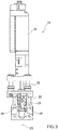
- the valve 21 comprises a valve body 22 having a longitudinal axis 23; a radial hole 24 to let the gas into the valve body 22; and a radial hole 25 to let the gas out of the valve body 22.
- the valve 21 further comprises a shutter 26, which is coupled to the valve body 22 in a sliding manner so as to move parallel to the axis 23 between a closing position and an opening position to close and open the hole 24.
- the shutter 26 comprises a substantially cylindrical portion 27, which is engaged in the valve body 22 in a sliding manner; and an end portion 28 with the shape of a truncated cone.
- the shutter 26 is further provided with at least one recess 29 (in the case in point, three recesses 29 uniformly distributed around the axis 23), which is obtained on an outer surface of the shutter 26 starting from a free end of the portion 28.
- the recess 29 extends along the portion 28 and at least part of the portion 27, faces the hole 24 and is substantially V-shaped.
- the recess 29 is delimited by two substantially flat side flanks 30 and has, perpendicularly to the axis 23, a cross section that decreases along the axis 23 starting from a free end of the shutter 26.
- the shutter 26 is axially moved between its opening and closing positions by an operating motor 31 having an output shaft 32, which is mounted coaxially to the axis 23 and is coupled to the shutter 26 by means of a screw-nut coupling.
- the shutter 26 is moved by the motor 31 along the vale body 22 so as to selectively control the gas flow rate fed to the heating device 19 and, hence, to the feeding device 12 depending on the axial position of the portion 28 shaped like a truncated cone and of the recess 29.
- the machine 1 further comprises an electronic control unit 33, which is connected to the detection device 20 and to the operating device 31 so as to selectively control the operation of the motor 31 depending on a signal coming from the device 20.
- the device 20 and the electronic control unit 33 allow operators to carry out a feedback control of the axial position of the shutter 26, so as to always keep the gas flow rate fed to the device 12 constant.
- the electronic control unit 33 is further provided with a memory 34 to store a plurality of values of the gas flow rate, each associated with a relative type of finishing edge (not shown herein).
- the electronic control unit 33 further comprises a selector device 35 to select the type of finishing edge (not shown herein) and is configured to control the selective operation of the motor 31 depending on the type of finishing edge (not shown herein) selected by the device 35.
- the presence of the operating motor 31 and the connection of the electronic control unit 33 to the detection device 20 and to the operating motor 31 allow to control, with utmost precision and with great flexibility, the gas flow rate fed to the heating device 19 and, hence, to the feeding device 12.
Landscapes
- Engineering & Computer Science (AREA)
- General Engineering & Computer Science (AREA)
- Mechanical Engineering (AREA)
- Life Sciences & Earth Sciences (AREA)
- Wood Science & Technology (AREA)
- Forests & Forestry (AREA)
- Manufacturing & Machinery (AREA)
- Lining Or Joining Of Plastics Or The Like (AREA)
Applications Claiming Priority (1)
| Application Number | Priority Date | Filing Date | Title |
|---|---|---|---|
| IT102016000128908A IT201600128908A1 (it) | 2016-12-20 | 2016-12-20 | Macchina per la bordatura di pannelli di legno o simili |
Publications (3)
| Publication Number | Publication Date |
|---|---|
| EP3338975A2 true EP3338975A2 (de) | 2018-06-27 |
| EP3338975A3 EP3338975A3 (de) | 2018-07-11 |
| EP3338975B1 EP3338975B1 (de) | 2020-02-05 |
Family
ID=58545145
Family Applications (1)
| Application Number | Title | Priority Date | Filing Date |
|---|---|---|---|
| EP17206803.3A Active EP3338975B1 (de) | 2016-12-20 | 2017-12-12 | Maschine zur kantenleimung von platten aus holz oder dergleichen |
Country Status (2)
| Country | Link |
|---|---|
| EP (1) | EP3338975B1 (de) |
| IT (1) | IT201600128908A1 (de) |
Family Cites Families (8)
| Publication number | Priority date | Publication date | Assignee | Title |
|---|---|---|---|---|
| US2014314A (en) * | 1931-07-22 | 1935-09-10 | Phillips Petroleum Co | Adjustable orifice valve |
| US2541176A (en) * | 1945-01-22 | 1951-02-13 | Mason Neilan Regulator Company | Control valve |
| US4222812A (en) * | 1978-06-29 | 1980-09-16 | Lof Plastics, Inc. | Hot air edge banding machine |
| GB2081642B (en) * | 1980-08-11 | 1984-05-16 | Janssens W J Ind Nz Ltd | Method and apparatus for adhering bands or tapes to surfaces |
| SE466114B (sv) * | 1990-05-14 | 1991-12-16 | Tetra Pak Holdings Sa | Reglerkaegla |
| SE508979C2 (sv) * | 1996-07-11 | 1998-11-23 | Tac Ab | Ventilkägla, ventil och sätt att framställa en ventilkägla |
| US6609697B2 (en) * | 2001-09-06 | 2003-08-26 | Robert Andreas Gsteu | Vacuum control valve |
| US6926249B2 (en) * | 2002-06-28 | 2005-08-09 | Invensys Building Systems, Inc. | Precision modulating globe valve |
-
2016
- 2016-12-20 IT IT102016000128908A patent/IT201600128908A1/it unknown
-
2017
- 2017-12-12 EP EP17206803.3A patent/EP3338975B1/de active Active
Non-Patent Citations (1)
| Title |
|---|
| None |
Also Published As
| Publication number | Publication date |
|---|---|
| IT201600128908A1 (it) | 2018-06-20 |
| EP3338975B1 (de) | 2020-02-05 |
| EP3338975A3 (de) | 2018-07-11 |
Similar Documents
| Publication | Publication Date | Title |
|---|---|---|
| ES2261797T3 (es) | Maquina para la fabricacion de bolsas. | |
| EP3533573B1 (de) | Maschine zur bearbeitung von platten aus holz oder dergleichen | |
| FI119469B (fi) | Laitteisto liiman annostelemiseksi liikkuvalle tasomaiselle kohteelle | |
| KR101551936B1 (ko) | 비닐제조장치 | |
| JP4510472B2 (ja) | 包装材に接着剤を付与する方法と装置 | |
| IT201600095770A1 (it) | Macchina per la produzione di guarnizioni spiralizzate | |
| KR20190081607A (ko) | 호스 절단장치 | |
| EP2862615B1 (de) | Heissklebstoff-Auftragvorrichtung | |
| EP3338975B1 (de) | Maschine zur kantenleimung von platten aus holz oder dergleichen | |
| EP2902161B1 (de) | Maschine zur kantenbearbeitung von holzpaneelen oder dergleichen | |
| US20170080646A1 (en) | Fiber placement machine roller with vaccum assisted tow handling | |
| EP3212391B1 (de) | Maschine zur herstellung von pappröhren | |
| DE102018208062A1 (de) | Andrückvorrichtung zum Andrücken eines Beschichtungsmaterials gegen platten- oder leistenförmige Werkstücke | |
| EP2902160B1 (de) | Maschine zur kantenbearbeitung von holzpaneelen oder dergleichen | |
| KR20070072507A (ko) | 공기 타이어의 제조 방법 및 장치 | |
| CN104803231A (zh) | 一种生料带绕线机 | |
| CN105876849B (zh) | 用于制造烟草加工工业的制品的设备 | |
| EP2845468B1 (de) | Pasta-Filata-Formmaschine | |
| CN103402751B (zh) | 用于生产管的机器及其相关方法 | |
| EP3517264B1 (de) | Kantenverleimungsanordnung und verfahren zur kantenverleimung von platten aus holz oder dergleichen | |
| EP0995959B1 (de) | Trocknungsvorrichtung zum Trocknen von schüttfähigem Material | |
| WO2016207059A1 (de) | Verpackungsmaschine mit einer motorischen drossel | |
| JP6597114B2 (ja) | 塗布装置及び塗布方法 | |
| EP3020669B1 (de) | Vorrichtung zum glätten einer materialbahn wie einer papierbahn | |
| CN204607259U (zh) | 一种生料带绕线机 |
Legal Events
| Date | Code | Title | Description |
|---|---|---|---|
| PUAI | Public reference made under article 153(3) epc to a published international application that has entered the european phase |
Free format text: ORIGINAL CODE: 0009012 |
|
| STAA | Information on the status of an ep patent application or granted ep patent |
Free format text: STATUS: THE APPLICATION HAS BEEN PUBLISHED |
|
| PUAL | Search report despatched |
Free format text: ORIGINAL CODE: 0009013 |
|
| AK | Designated contracting states |
Kind code of ref document: A2 Designated state(s): AL AT BE BG CH CY CZ DE DK EE ES FI FR GB GR HR HU IE IS IT LI LT LU LV MC MK MT NL NO PL PT RO RS SE SI SK SM TR |
|
| AX | Request for extension of the european patent |
Extension state: BA ME |
|
| AK | Designated contracting states |
Kind code of ref document: A3 Designated state(s): AL AT BE BG CH CY CZ DE DK EE ES FI FR GB GR HR HU IE IS IT LI LT LU LV MC MK MT NL NO PL PT RO RS SE SI SK SM TR |
|
| AX | Request for extension of the european patent |
Extension state: BA ME |
|
| RIC1 | Information provided on ipc code assigned before grant |
Ipc: F16K 3/24 20060101ALI20180604BHEP Ipc: F16K 3/34 20060101ALI20180604BHEP Ipc: B29C 63/00 20060101ALI20180604BHEP Ipc: B27D 5/00 20060101AFI20180604BHEP |
|
| STAA | Information on the status of an ep patent application or granted ep patent |
Free format text: STATUS: REQUEST FOR EXAMINATION WAS MADE |
|
| 17P | Request for examination filed |
Effective date: 20190110 |
|
| RBV | Designated contracting states (corrected) |
Designated state(s): AL AT BE BG CH CY CZ DE DK EE ES FI FR GB GR HR HU IE IS IT LI LT LU LV MC MK MT NL NO PL PT RO RS SE SI SK SM TR |
|
| RIC1 | Information provided on ipc code assigned before grant |
Ipc: B29C 63/00 20060101ALI20190710BHEP Ipc: B27D 5/00 20060101AFI20190710BHEP Ipc: F16K 3/34 20060101ALI20190710BHEP Ipc: F16K 3/24 20060101ALI20190710BHEP |
|
| GRAP | Despatch of communication of intention to grant a patent |
Free format text: ORIGINAL CODE: EPIDOSNIGR1 |
|
| STAA | Information on the status of an ep patent application or granted ep patent |
Free format text: STATUS: GRANT OF PATENT IS INTENDED |
|
| INTG | Intention to grant announced |
Effective date: 20190912 |
|
| GRAS | Grant fee paid |
Free format text: ORIGINAL CODE: EPIDOSNIGR3 |
|
| GRAA | (expected) grant |
Free format text: ORIGINAL CODE: 0009210 |
|
| STAA | Information on the status of an ep patent application or granted ep patent |
Free format text: STATUS: THE PATENT HAS BEEN GRANTED |
|
| AK | Designated contracting states |
Kind code of ref document: B1 Designated state(s): AL AT BE BG CH CY CZ DE DK EE ES FI FR GB GR HR HU IE IS IT LI LT LU LV MC MK MT NL NO PL PT RO RS SE SI SK SM TR |
|
| REG | Reference to a national code |
Ref country code: GB Ref legal event code: FG4D |
|
| REG | Reference to a national code |
Ref country code: AT Ref legal event code: REF Ref document number: 1229596 Country of ref document: AT Kind code of ref document: T Effective date: 20200215 |
|
| REG | Reference to a national code |
Ref country code: DE Ref legal event code: R096 Ref document number: 602017011364 Country of ref document: DE |
|
| REG | Reference to a national code |
Ref country code: IE Ref legal event code: FG4D |
|
| REG | Reference to a national code |
Ref country code: CH Ref legal event code: EP |
|
| REG | Reference to a national code |
Ref country code: NL Ref legal event code: MP Effective date: 20200205 |
|
| PG25 | Lapsed in a contracting state [announced via postgrant information from national office to epo] |
Ref country code: NO Free format text: LAPSE BECAUSE OF FAILURE TO SUBMIT A TRANSLATION OF THE DESCRIPTION OR TO PAY THE FEE WITHIN THE PRESCRIBED TIME-LIMIT Effective date: 20200505 Ref country code: RS Free format text: LAPSE BECAUSE OF FAILURE TO SUBMIT A TRANSLATION OF THE DESCRIPTION OR TO PAY THE FEE WITHIN THE PRESCRIBED TIME-LIMIT Effective date: 20200205 Ref country code: PT Free format text: LAPSE BECAUSE OF FAILURE TO SUBMIT A TRANSLATION OF THE DESCRIPTION OR TO PAY THE FEE WITHIN THE PRESCRIBED TIME-LIMIT Effective date: 20200628 Ref country code: FI Free format text: LAPSE BECAUSE OF FAILURE TO SUBMIT A TRANSLATION OF THE DESCRIPTION OR TO PAY THE FEE WITHIN THE PRESCRIBED TIME-LIMIT Effective date: 20200205 |
|
| REG | Reference to a national code |
Ref country code: LT Ref legal event code: MG4D |
|
| PG25 | Lapsed in a contracting state [announced via postgrant information from national office to epo] |
Ref country code: LV Free format text: LAPSE BECAUSE OF FAILURE TO SUBMIT A TRANSLATION OF THE DESCRIPTION OR TO PAY THE FEE WITHIN THE PRESCRIBED TIME-LIMIT Effective date: 20200205 Ref country code: IS Free format text: LAPSE BECAUSE OF FAILURE TO SUBMIT A TRANSLATION OF THE DESCRIPTION OR TO PAY THE FEE WITHIN THE PRESCRIBED TIME-LIMIT Effective date: 20200605 Ref country code: SE Free format text: LAPSE BECAUSE OF FAILURE TO SUBMIT A TRANSLATION OF THE DESCRIPTION OR TO PAY THE FEE WITHIN THE PRESCRIBED TIME-LIMIT Effective date: 20200205 Ref country code: BG Free format text: LAPSE BECAUSE OF FAILURE TO SUBMIT A TRANSLATION OF THE DESCRIPTION OR TO PAY THE FEE WITHIN THE PRESCRIBED TIME-LIMIT Effective date: 20200505 Ref country code: HR Free format text: LAPSE BECAUSE OF FAILURE TO SUBMIT A TRANSLATION OF THE DESCRIPTION OR TO PAY THE FEE WITHIN THE PRESCRIBED TIME-LIMIT Effective date: 20200205 Ref country code: GR Free format text: LAPSE BECAUSE OF FAILURE TO SUBMIT A TRANSLATION OF THE DESCRIPTION OR TO PAY THE FEE WITHIN THE PRESCRIBED TIME-LIMIT Effective date: 20200506 |
|
| PG25 | Lapsed in a contracting state [announced via postgrant information from national office to epo] |
Ref country code: NL Free format text: LAPSE BECAUSE OF FAILURE TO SUBMIT A TRANSLATION OF THE DESCRIPTION OR TO PAY THE FEE WITHIN THE PRESCRIBED TIME-LIMIT Effective date: 20200205 |
|
| PG25 | Lapsed in a contracting state [announced via postgrant information from national office to epo] |
Ref country code: ES Free format text: LAPSE BECAUSE OF FAILURE TO SUBMIT A TRANSLATION OF THE DESCRIPTION OR TO PAY THE FEE WITHIN THE PRESCRIBED TIME-LIMIT Effective date: 20200205 Ref country code: SK Free format text: LAPSE BECAUSE OF FAILURE TO SUBMIT A TRANSLATION OF THE DESCRIPTION OR TO PAY THE FEE WITHIN THE PRESCRIBED TIME-LIMIT Effective date: 20200205 Ref country code: LT Free format text: LAPSE BECAUSE OF FAILURE TO SUBMIT A TRANSLATION OF THE DESCRIPTION OR TO PAY THE FEE WITHIN THE PRESCRIBED TIME-LIMIT Effective date: 20200205 Ref country code: SM Free format text: LAPSE BECAUSE OF FAILURE TO SUBMIT A TRANSLATION OF THE DESCRIPTION OR TO PAY THE FEE WITHIN THE PRESCRIBED TIME-LIMIT Effective date: 20200205 Ref country code: EE Free format text: LAPSE BECAUSE OF FAILURE TO SUBMIT A TRANSLATION OF THE DESCRIPTION OR TO PAY THE FEE WITHIN THE PRESCRIBED TIME-LIMIT Effective date: 20200205 Ref country code: DK Free format text: LAPSE BECAUSE OF FAILURE TO SUBMIT A TRANSLATION OF THE DESCRIPTION OR TO PAY THE FEE WITHIN THE PRESCRIBED TIME-LIMIT Effective date: 20200205 Ref country code: RO Free format text: LAPSE BECAUSE OF FAILURE TO SUBMIT A TRANSLATION OF THE DESCRIPTION OR TO PAY THE FEE WITHIN THE PRESCRIBED TIME-LIMIT Effective date: 20200205 Ref country code: CZ Free format text: LAPSE BECAUSE OF FAILURE TO SUBMIT A TRANSLATION OF THE DESCRIPTION OR TO PAY THE FEE WITHIN THE PRESCRIBED TIME-LIMIT Effective date: 20200205 |
|
| REG | Reference to a national code |
Ref country code: DE Ref legal event code: R097 Ref document number: 602017011364 Country of ref document: DE |
|
| REG | Reference to a national code |
Ref country code: AT Ref legal event code: MK05 Ref document number: 1229596 Country of ref document: AT Kind code of ref document: T Effective date: 20200205 |
|
| PLBE | No opposition filed within time limit |
Free format text: ORIGINAL CODE: 0009261 |
|
| STAA | Information on the status of an ep patent application or granted ep patent |
Free format text: STATUS: NO OPPOSITION FILED WITHIN TIME LIMIT |
|
| 26N | No opposition filed |
Effective date: 20201106 |
|
| PG25 | Lapsed in a contracting state [announced via postgrant information from national office to epo] |
Ref country code: AT Free format text: LAPSE BECAUSE OF FAILURE TO SUBMIT A TRANSLATION OF THE DESCRIPTION OR TO PAY THE FEE WITHIN THE PRESCRIBED TIME-LIMIT Effective date: 20200205 |
|
| PG25 | Lapsed in a contracting state [announced via postgrant information from national office to epo] |
Ref country code: SI Free format text: LAPSE BECAUSE OF FAILURE TO SUBMIT A TRANSLATION OF THE DESCRIPTION OR TO PAY THE FEE WITHIN THE PRESCRIBED TIME-LIMIT Effective date: 20200205 Ref country code: PL Free format text: LAPSE BECAUSE OF FAILURE TO SUBMIT A TRANSLATION OF THE DESCRIPTION OR TO PAY THE FEE WITHIN THE PRESCRIBED TIME-LIMIT Effective date: 20200205 |
|
| REG | Reference to a national code |
Ref country code: CH Ref legal event code: PL |
|
| PG25 | Lapsed in a contracting state [announced via postgrant information from national office to epo] |
Ref country code: MC Free format text: LAPSE BECAUSE OF FAILURE TO SUBMIT A TRANSLATION OF THE DESCRIPTION OR TO PAY THE FEE WITHIN THE PRESCRIBED TIME-LIMIT Effective date: 20200205 |
|
| REG | Reference to a national code |
Ref country code: BE Ref legal event code: MM Effective date: 20201231 |
|
| PG25 | Lapsed in a contracting state [announced via postgrant information from national office to epo] |
Ref country code: LU Free format text: LAPSE BECAUSE OF NON-PAYMENT OF DUE FEES Effective date: 20201212 Ref country code: IE Free format text: LAPSE BECAUSE OF NON-PAYMENT OF DUE FEES Effective date: 20201212 Ref country code: FR Free format text: LAPSE BECAUSE OF NON-PAYMENT OF DUE FEES Effective date: 20201231 |
|
| PG25 | Lapsed in a contracting state [announced via postgrant information from national office to epo] |
Ref country code: LI Free format text: LAPSE BECAUSE OF NON-PAYMENT OF DUE FEES Effective date: 20201231 Ref country code: CH Free format text: LAPSE BECAUSE OF NON-PAYMENT OF DUE FEES Effective date: 20201231 |
|
| PG25 | Lapsed in a contracting state [announced via postgrant information from national office to epo] |
Ref country code: TR Free format text: LAPSE BECAUSE OF FAILURE TO SUBMIT A TRANSLATION OF THE DESCRIPTION OR TO PAY THE FEE WITHIN THE PRESCRIBED TIME-LIMIT Effective date: 20200205 Ref country code: MT Free format text: LAPSE BECAUSE OF FAILURE TO SUBMIT A TRANSLATION OF THE DESCRIPTION OR TO PAY THE FEE WITHIN THE PRESCRIBED TIME-LIMIT Effective date: 20200205 Ref country code: CY Free format text: LAPSE BECAUSE OF FAILURE TO SUBMIT A TRANSLATION OF THE DESCRIPTION OR TO PAY THE FEE WITHIN THE PRESCRIBED TIME-LIMIT Effective date: 20200205 |
|
| PG25 | Lapsed in a contracting state [announced via postgrant information from national office to epo] |
Ref country code: MK Free format text: LAPSE BECAUSE OF FAILURE TO SUBMIT A TRANSLATION OF THE DESCRIPTION OR TO PAY THE FEE WITHIN THE PRESCRIBED TIME-LIMIT Effective date: 20200205 Ref country code: AL Free format text: LAPSE BECAUSE OF FAILURE TO SUBMIT A TRANSLATION OF THE DESCRIPTION OR TO PAY THE FEE WITHIN THE PRESCRIBED TIME-LIMIT Effective date: 20200205 |
|
| PG25 | Lapsed in a contracting state [announced via postgrant information from national office to epo] |
Ref country code: BE Free format text: LAPSE BECAUSE OF NON-PAYMENT OF DUE FEES Effective date: 20201231 |
|
| GBPC | Gb: european patent ceased through non-payment of renewal fee |
Effective date: 20211212 |
|
| PG25 | Lapsed in a contracting state [announced via postgrant information from national office to epo] |
Ref country code: GB Free format text: LAPSE BECAUSE OF NON-PAYMENT OF DUE FEES Effective date: 20211212 |
|
| PGFP | Annual fee paid to national office [announced via postgrant information from national office to epo] |
Ref country code: IT Payment date: 20251117 Year of fee payment: 9 |
|
| PGFP | Annual fee paid to national office [announced via postgrant information from national office to epo] |
Ref country code: DE Payment date: 20251229 Year of fee payment: 9 |