EP3339076A1 - Antriebseinheit für grätschsitzfahrzeug - Google Patents
Antriebseinheit für grätschsitzfahrzeug Download PDFInfo
- Publication number
- EP3339076A1 EP3339076A1 EP16838962.5A EP16838962A EP3339076A1 EP 3339076 A1 EP3339076 A1 EP 3339076A1 EP 16838962 A EP16838962 A EP 16838962A EP 3339076 A1 EP3339076 A1 EP 3339076A1
- Authority
- EP
- European Patent Office
- Prior art keywords
- transmission case
- duct cover
- cover
- case cover
- wind
- Prior art date
- Legal status (The legal status is an assumption and is not a legal conclusion. Google has not performed a legal analysis and makes no representation as to the accuracy of the status listed.)
- Granted
Links
Images




Classifications
-
- B—PERFORMING OPERATIONS; TRANSPORTING
- B60—VEHICLES IN GENERAL
- B60K—ARRANGEMENT OR MOUNTING OF PROPULSION UNITS OR OF TRANSMISSIONS IN VEHICLES; ARRANGEMENT OR MOUNTING OF PLURAL DIVERSE PRIME-MOVERS IN VEHICLES; AUXILIARY DRIVES FOR VEHICLES; INSTRUMENTATION OR DASHBOARDS FOR VEHICLES; ARRANGEMENTS IN CONNECTION WITH COOLING, AIR INTAKE, GAS EXHAUST OR FUEL SUPPLY OF PROPULSION UNITS IN VEHICLES
- B60K17/00—Arrangement or mounting of transmissions in vehicles
-
- B—PERFORMING OPERATIONS; TRANSPORTING
- B62—LAND VEHICLES FOR TRAVELLING OTHERWISE THAN ON RAILS
- B62H—CYCLE STANDS; SUPPORTS OR HOLDERS FOR PARKING OR STORING CYCLES; APPLIANCES PREVENTING OR INDICATING UNAUTHORIZED USE OR THEFT OF CYCLES; LOCKS INTEGRAL WITH CYCLES; DEVICES FOR LEARNING TO RIDE CYCLES
- B62H1/00—Supports or stands forming part of or attached to cycles
- B62H1/02—Articulated stands, e.g. in the shape of hinged arms
-
- B—PERFORMING OPERATIONS; TRANSPORTING
- B62—LAND VEHICLES FOR TRAVELLING OTHERWISE THAN ON RAILS
- B62J—CYCLE SADDLES OR SEATS; AUXILIARY DEVICES OR ACCESSORIES SPECIALLY ADAPTED TO CYCLES AND NOT OTHERWISE PROVIDED FOR, e.g. ARTICLE CARRIERS OR CYCLE PROTECTORS
- B62J13/00—Guards for chain, chain drive or equivalent drive, e.g. belt drive
- B62J13/04—Guards for chain, chain drive or equivalent drive, e.g. belt drive completely enclosing the chain drive or the like
-
- B—PERFORMING OPERATIONS; TRANSPORTING
- B62—LAND VEHICLES FOR TRAVELLING OTHERWISE THAN ON RAILS
- B62K—CYCLES; CYCLE FRAMES; CYCLE STEERING DEVICES; RIDER-OPERATED TERMINAL CONTROLS SPECIALLY ADAPTED FOR CYCLES; CYCLE AXLE SUSPENSIONS; CYCLE SIDECARS, FORECARS, OR THE LIKE
- B62K25/00—Axle suspensions
- B62K25/04—Axle suspensions for mounting axles resiliently on cycle frame or fork
- B62K25/28—Axle suspensions for mounting axles resiliently on cycle frame or fork with pivoted chain-stay
- B62K25/283—Axle suspensions for mounting axles resiliently on cycle frame or fork with pivoted chain-stay for cycles without a pedal crank, e.g. motorcycles
-
- B—PERFORMING OPERATIONS; TRANSPORTING
- B62—LAND VEHICLES FOR TRAVELLING OTHERWISE THAN ON RAILS
- B62K—CYCLES; CYCLE FRAMES; CYCLE STEERING DEVICES; RIDER-OPERATED TERMINAL CONTROLS SPECIALLY ADAPTED FOR CYCLES; CYCLE AXLE SUSPENSIONS; CYCLE SIDECARS, FORECARS, OR THE LIKE
- B62K25/00—Axle suspensions
- B62K25/04—Axle suspensions for mounting axles resiliently on cycle frame or fork
- B62K25/28—Axle suspensions for mounting axles resiliently on cycle frame or fork with pivoted chain-stay
- B62K25/32—Axle suspensions for mounting axles resiliently on cycle frame or fork with pivoted chain-stay the chain-stay forming a chain-guard
-
- B—PERFORMING OPERATIONS; TRANSPORTING
- B62—LAND VEHICLES FOR TRAVELLING OTHERWISE THAN ON RAILS
- B62M—RIDER PROPULSION OF WHEELED VEHICLES OR SLEDGES; POWERED PROPULSION OF SLEDGES OR SINGLE-TRACK CYCLES; TRANSMISSIONS SPECIALLY ADAPTED FOR SUCH VEHICLES
- B62M9/00—Transmissions characterised by use of an endless chain, belt, or the like
- B62M9/04—Transmissions characterised by use of an endless chain, belt, or the like of changeable ratio
- B62M9/06—Transmissions characterised by use of an endless chain, belt, or the like of changeable ratio using a single chain, belt, or the like
- B62M9/08—Transmissions characterised by use of an endless chain, belt, or the like of changeable ratio using a single chain, belt, or the like involving eccentrically- mounted or elliptically-shaped driving or driven wheel; with expansible driving or driven wheel
-
- F—MECHANICAL ENGINEERING; LIGHTING; HEATING; WEAPONS; BLASTING
- F16—ENGINEERING ELEMENTS AND UNITS; GENERAL MEASURES FOR PRODUCING AND MAINTAINING EFFECTIVE FUNCTIONING OF MACHINES OR INSTALLATIONS; THERMAL INSULATION IN GENERAL
- F16H—GEARING
- F16H57/00—General details of gearing
- F16H57/04—Features relating to lubrication or cooling or heating
- F16H57/0412—Cooling or heating; Control of temperature
- F16H57/0415—Air cooling or ventilation; Heat exchangers; Thermal insulations
- F16H57/0416—Air cooling or ventilation
-
- F—MECHANICAL ENGINEERING; LIGHTING; HEATING; WEAPONS; BLASTING
- F16—ENGINEERING ELEMENTS AND UNITS; GENERAL MEASURES FOR PRODUCING AND MAINTAINING EFFECTIVE FUNCTIONING OF MACHINES OR INSTALLATIONS; THERMAL INSULATION IN GENERAL
- F16H—GEARING
- F16H57/00—General details of gearing
- F16H57/04—Features relating to lubrication or cooling or heating
- F16H57/048—Type of gearings to be lubricated, cooled or heated
- F16H57/0487—Friction gearings
- F16H57/0489—Friction gearings with endless flexible members, e.g. belt CVTs
-
- B—PERFORMING OPERATIONS; TRANSPORTING
- B60—VEHICLES IN GENERAL
- B60Y—INDEXING SCHEME RELATING TO ASPECTS CROSS-CUTTING VEHICLE TECHNOLOGY
- B60Y2200/00—Type of vehicle
- B60Y2200/10—Road Vehicles
- B60Y2200/12—Motorcycles, Trikes; Quads; Scooters
- B60Y2200/126—Scooters
-
- B—PERFORMING OPERATIONS; TRANSPORTING
- B62—LAND VEHICLES FOR TRAVELLING OTHERWISE THAN ON RAILS
- B62K—CYCLES; CYCLE FRAMES; CYCLE STEERING DEVICES; RIDER-OPERATED TERMINAL CONTROLS SPECIALLY ADAPTED FOR CYCLES; CYCLE AXLE SUSPENSIONS; CYCLE SIDECARS, FORECARS, OR THE LIKE
- B62K2202/00—Motorised scooters
-
- F—MECHANICAL ENGINEERING; LIGHTING; HEATING; WEAPONS; BLASTING
- F16—ENGINEERING ELEMENTS AND UNITS; GENERAL MEASURES FOR PRODUCING AND MAINTAINING EFFECTIVE FUNCTIONING OF MACHINES OR INSTALLATIONS; THERMAL INSULATION IN GENERAL
- F16H—GEARING
- F16H57/00—General details of gearing
- F16H57/02—Gearboxes; Mounting gearing therein
- F16H2057/02039—Gearboxes for particular applications
- F16H2057/02043—Gearboxes for particular applications for vehicle transmissions
- F16H2057/02065—Gearboxes for particular applications for vehicle transmissions for motorcycles or squads
Definitions
- the present invention relates to a power unit of a saddle-type vehicle.
- a power unit mounted on a saddle-type vehicle which has a transmission case internally housing a belt-type continuously variable transmission and joined to a crankcase that bears a crankshaft of an internal combustion engine and extends to lateral side of the rear wheel of the vehicle.
- a transmission case cover covers the lateral side of the transmission case with respect the vehicle-width direction.
- a cooling wind is introduced through a cooling wind inlet formed at a front part of the transmission case to define a belt chamber for housing the belt-type continuously variable transmission of the power unit, whereby the belt-type continuously variable transmission is cooled.
- the front part of the transmission case cover made of a metal, including the cooling wind inlet, is covered with a wind-guide duct cover, while the part other than the front part, not covered by the wind-guide duct cover, has a comparatively large surface area exposed to the outside, so that the transmission case cover is efficiently cooled by heat dissipation due to the exposure to the vehicle travel wind. This promotes cooling of the belt-type continuously variable transmission in the belt chamber by the cooling wind introduced through the cooling wind inlet into the belt chamber.
- a main stand pivotally supported on a lower part of the crankcase is provided to swing between an erection position in which the main stand supports the vehicle body at the time of parking and a retraction position in which the main stand is made to lie along the lower surface of the transmission case at the time of traveling (for example, refer to Patent Document 1).
- Patent Document 1 WO 2011/027445 A1
- Patent Document 1 discloses a saddle-type vehicle in a state in which a main stand is erected and the vehicle body is supported thereby (see FIG. 1 in Patent Document 1).
- the main stand has an operation arm protruding outward in a curved shape in vehicle width-direction from a leg part that erects to support the vehicle body.
- the wind-guide duct cover covers only the front part of the transmission case cover.
- the operation arm protruding from the leg part is caused to extend upward along the laterally outer side surface of the transmission case cover uncovered by the wind-guide duct cover and is exposed on the rear side, and a foot-rest part on the tip is positioned adjacent to the upper edge of the transmission case cover.
- the rider When erecting the main stand in the retracted state, the rider puts his or her foot on the foot-rest part on the tip of the operation arm extending upward along the laterally outer side surface of the transmission case cover and presses down the foot-rest part to erect the main stand.
- the foot-rest part is located close to the laterally outer side of the transmission case cover in the vehicle-width direction. Therefore, the rider's foot tends to hit the exposed transmission case cover when the rider erects the main stand. If a painted surface of the transmission case cover made of a metal is scratched, there is a possibility that the scratch is conspicuous and impairs the appearance.
- the present invention has been made in view of the foregoing problem and an object thereof is to provide a power unit of a saddle-type vehicle that can suppress scratching of a painted surface of the transmission case cover accompanying erection operation of the main stand while exposing the transmission case cover to sufficiently maintain a cooling effect for a belt chamber by the vehicle travel wind.
- a power unit of a saddle-type vehicle including an internal combustion engine and a belt-type continuously variable transmission integrally configured and mounted on a saddle-type vehicle, the power unit comprising: a transmission case joined to a crankcase bearing a crankshaft, extending in a vehicle-width direction, of the internal combustion engine, the transmission case extending to a lateral side of a rear wheel of the vehicle; a transmission case cover made of a metal and covering a lateral side of the transmission case, with respect to the vehicle-width direction, to cooperate with the transmission case to define a belt chamber, the transmission case cover having an open cooling wind inlet formed at a front part thereof to introduce a cooling wind into the belt chamber; a wind-guide duct cover covering at least a front part including the cooling wind inlet of the transmission case cover from the lateral side with respect to the vehicle-width direction, in a manner to introduce external air into the cooling wind inlet; and a main stand pivotally supported by
- the duct cover rear part of the wind-guide duct cover is extended to a rearward position beyond the position of the operation part when the main stand is retracted. Therefore, the duct cover rear part is arranged to cover the transmission case cover in a region in which the rider's foot tends to hit when the rider puts the foot on the operation part of the main stand to erect the main stand. This can suppress scratching of the transmission case cover made of metal at the time of erection operation and keep the appearance good.
- the wind-guide duct cover mainly covers at least the front part of the transmission case cover and the duct cover rear part partly covers the transmission case cover to a rearward area beyond the operation part of the main stand in its retraction state.
- the part that is not covered by the wind-guide duct cover in the transmission case cover can be exposed in a comparatively-large area.
- the transmission case cover can be efficiently cooled as a whole by heat dissipation due to the exposure of the exposed region of the transmission case cover made of metal to the vehicle running wind, and the effect of promoting cooling of the belt-type continuously variable transmission in the belt chamber by the cooling wind introduced through the cooling wind inlet into the belt chamber can also be maintained.
- the wind-guide duct cover including the duct cover rear part may be totally formed of a colored resin.
- the wind-guide duct cover is formed of a colored resin including the duct cover rear part disposed in the region against which the rider's foot tends to hit when the main stand is erected.
- the scratch can be made inconspicuous.
- the duct cover rear part may be disposed in such an area as to straddle, in an upward-downward direction, a virtual plane including both center axis lines of the crankshaft, as a front drive shaft, and a rear driven shaft between which a belt of the belt-type continuously variable transmission is stretched.
- the vicinity of the virtual plane including both the center axis lines of the front drive shaft (crankshaft) and the rear driven shaft between which the belt of the belt-type continuously variable transmission is stretched in the transmission case cover is a region where the transmission case cover bulges outward in the vehicle-width direction to the largest extent and thus is a region against which the rider's foot tends to hit frequently.
- the duct cover rear part may be located in an intermediate area between an upper edge and a lower edge of the transmission case cover in side view; and the transmission case cover may have a case cover exposed region uncovered by the wind-guide duct cover to be exposed to outside, and the case cover exposed region may include a rear exposed part on the rear side relative to the duct cover rear part, and upper and lower exposed parts formed to extend forward from the rear exposed part along upper and lower sides of the duct cover rear part.
- the exposed region of the transmission case cover uncovered by the wind-guide duct cover includes the rear exposed part and the upper and lower exposed parts formed to extend forward from the rear exposed part on the upper and lower sides of the duct cover rear part. Therefore, although the duct cover rear part exists on the wind-guide duct cover, a large surface area can be ensured as the surface area of the case cover exposed region that is not covered by the wind-guide duct cover. Thus, heat dissipation of the transmission case cover by the vehicle running wind can be efficiently carried out and an increased cooling effect for the belt-type continuously variable transmission can be expected.
- the transmission case cover may have a fitting recess part recessed inward in the vehicle-width direction to receive therein the duct cover rear part.
- the duct cover rear part located in the region bulging outward in the vehicle-width direction to the largest extent is fitted in the fitting recess part formed in the transmission case cover. This can suppress protrusion of the duct cover rear part to the outside in the vehicle-width direction and suppress also hitting of the rider's foot against the duct cover rear part.
- the duct cover rear part may have a duct cover rear recess part recessed inward in the vehicle-width direction in a region including the virtual plane.
- the rear cover side recess part that recesses inward in the vehicle-width direction is formed in the region including the virtual plane that bulges outward in the vehicle-width direction to the largest extent and against which the rider's foot tends to hit.
- hitting of the rider's foot against the duct cover rear part can also be suppressed.
- the duct cover rear part may be co-fastened to the transmission case together with the transmission case cover with a fastening bolt for fastening the transmission case cover to the transmission case.
- the duct cover rear part of the wind-guide duct cover is co-fastened to the transmission case together with the transmission case cover.
- the duct cover rear part can be stably fixed even when being elongated in the front-rear direction.
- the number of parts can be reduced because the wind-guide duct cover is co-fastened by the fastening bolt that fastens the transmission case cover to the transmission case.
- the transmission case cover may be formed with a fitting recess part recessed inward in the vehicle-width direction to receive therein the duct cover rear part; and the duct cover rear part may have a fastening seat face against which the fastening bolt is tightened, and the fastening seat face may be formed on a bottom surface of a bolt insertion recess part of the duct cover rear part, formed to be depressed inward in the vehicle-width direction onto a bottom surface of the fitting recess part of the transmission case cover.
- the fastening seat face, against which the fastening bolt is tightened in the duct cover rear part is formed at the bottom surface of the bolt insertion recess part in the duct cover rear part.
- the duct cover rear part is formed to be depressed inward in the vehicle-width direction to the bottom surface of the fitting recess part of the transmission case cover.
- the wind-guide duct cover may have a duct cover front major part covering the front part of the transmission case cover, the duct cover rear part being formed to extend to the rear from the duct cover front major part.
- the wind-guide duct cover is formed with the extension of the duct cover rear part toward the rear side from the duct cover front major part covering the front part of the transmission case cover.
- the duct cover front major part and the duct cover rear part are formed integrally and continuously in the wind-guide duct cover.
- the number of parts is reduced and assembling work and so forth are made easy.
- the wind-guide duct cover may include a duct cover front major part covering the front part of the transmission case cover, and the duct cover rear part may be separate from, and is disposed on the rear of the duct cover front major part.
- the duct cover front major part and the duct cover rear part of the wind-guide duct cover are divided into front and rear parts and the wind-guide duct cover is formed of separate members.
- the front major part of the wind-guide duct cover can be removed without removing the fastening bolt with which the co-fastening is made.
- maintainability in performing maintenance or the like is good.
- the duct cover rear part of the wind-guide duct cover is configured to extend to the rear-side position beyond the operation part when the main stand is retracted. Therefore, the duct cover rear part is disposed to cover the transmission case cover in a region against which the rider's foot tends to hit when the rider puts the foot on the operation part of the main stand to erect the main stand. This prevents the foot of the rider from hitting against the transmission case cover made of metal to an utmost degree, which can suppress scratching of the painted surface of the transmission case cover made of metal and maintains good appearance.
- the wind-guide duct cover mainly covers at least the front part of the transmission case cover and the duct cover rear part partly covers the transmission case cover in the rear-side area beyond the operation part of the main stand in the retraction position. Due to this, the part that is uncovered by the wind-guide duct cover in the transmission case cover can be exposed in a comparatively large area.
- the transmission case cover can be effectively cooled as a whole by heat dissipation due to the exposure of the exposed region of the transmission case cover made of metal to the running wind, and the effect of promoting cooling of the belt-type continuously variable transmission in the belt chamber by the cooling wind introduced through the cooling wind inlet into the belt chamber can also be maintained.
- a first embodiment according to the present invention will be described below with reference to FIG. 1 to FIG. 11 .
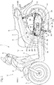
- FIG. 1 is a side view of a two-wheel motorcycle 1 that is a saddle-type vehicle equipped with a power unit of the first embodiment to which the present invention is applied.
- the front, rear, left, and right directions are in accordance with the normal basis in which the straight forwarding direction of the motorcycle 1 equipped with the power unit according to the present embodiment is defined as the front side.
- FR denotes the front side
- RR denotes the rear side
- LH denotes the left side
- RH denotes the right side.
- a vehicle body front portion 1f and a vehicle body rear portion 1r are joined with the intermediary of a low floor portion 1c, and a vehicle body frame that forms the framework of the vehicle body basically includes a down-tube 3 and main pipes 4.
- the down-tube 3 extends downward from a head pipe 2 of the vehicle body front portion 1f. This down-tube 3 bends to the horizontal direction at the lower end and extends rearward through the lower side of the floor portion 1c. At the rear end thereof, the pair of left and right main pipes 4 are joined thereto. The main pipes 4 rise upward from this joint part and bend to extend obliquely rearward.
- a seat 5 is disposed above these main pipes 4.
- a handlebar 6 pivotally supported by the head pipe 2 is provided above the head pipe 2 and a front fork 7 extends downward and a front wheel 8 is pivotally supported by the lower end thereof.
- the internal combustion engine E is a single-cylinder, four-stroke internal combustion engine.
- a cylinder block 22, a cylinder head 23, and a cylinder head cover 24 protrude forward from a crankcase 21c that bears a crankshaft 20 (see FIG. 2 ) while orienting the crankshaft 20 in the vehicle width direction.
- the engine largely tilts forward to a state close to a substantially horizontal state.
- a pair of left and right support brackets 12 extends downward from the lower end of the crankcase 21.
- hanger brackets 12h protrude forward. These hanger brackets 12h are joined to brackets 10 protruded rearward from the front lower parts of the main pipes 4 with the intermediary of link members 11, and the power unit P is swingably joined and supported with respect to the vehicle body.
- a rear wheel 15 is provided around a rear axle 14 that is an output shaft of a reduction gear mechanism Tr (see FIG. 2 ) provided at the rear part of the V-belt-type continuously variable transmission T.
- a rear cushion 17 is interposed between a support bracket 16, provided upright at the rear end of the V-belt-type continuously variable transmission T, and the rear part of the main pipe 4 (see FIG. 1 ).
- An intake pipe 25 extends from the upper part of the cylinder head 23 greatly tilted forward in the internal combustion engine E and curves rearward to reach an air cleaner 27 above the V-belt-type continuously variable transmission T, via a throttle body 26.
- an exhaust pipe 28 that extends downward from the lower part of the cylinder head 23 is bent rearward and biased toward the right side to extend rearward and to be joined to a muffler 29 on the right side of the rear wheel 21.
- a base end pivot shaft 31 of a main stand 30 is supported by the support brackets 12 extending from the lower end of the crankcase 21c, with the base end pivot shaft 31 oriented in the vehicle width direction.
- a pair of left and right leg parts 32 extend from the base end pivot shaft 31 in such a manner as to spread from each other toward the end and the left and right leg parts 32 are joined by a joint bar 32b (see FIG. 3 ).
- an operation arm 33 extends leftward from a region close to the tip end of the left leg part 32.
- a spring 36 is interposed between a hooking piece 35a at the central part of the leg part 32 and a hooking pin 35b near the upper side of the base end pivot shaft 31 of the support bracket 12.
- the spring 36 allows keeping of both states of erecting and lying of the leg parts 32 of the main stand 30.
- FIG. 1 the erecting state of the main stand 30 is depicted by a solid line and the retracted state (lying state of the leg parts 32) is depicted by a two-dot-chain line.
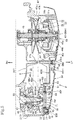
- FIGS. 2 and 3 the retracted state is depicted.
- the main stand 30 swings around the base end pivot shaft 31 and the leg parts 32 are erected as depicted in FIG. 1 to support the vehicle body.
- the leg parts 32 are swung upward and are made to lie substantially horizontally along the lower surface of the V-belt-type continuously variable transmission T to be set to the retracted state.
- the operation arm 33 extending leftward from the left leg part 32 is located to extend upward through a central part of the V-belt-type continuously variable transmission T with respect to the front-rear direction while curving from the lower surface of the transmission T along the left side surface thereof.
- a foot-rest plate 33a is fixed to the tip of the operation arm 33.
- the crankcase 21c that bears the crankshaft 20 while orienting the crankshaft 20 in the vehicle width direction is configured through left-right coalescence of a right crankcase portion 21R and a front part 21Tf of a transmission case 21T that is on the left side and is elongated in the front-rear direction (see FIG. 3 ).
- the transmission case 21T on the left side extends rearward from the front part 21Tf to a lateral side of the rear wheel 15.
- the front part 21Tf coalesces with the right crankcase portion 21R to form the crankcase 21c.
- the transmission case 21T extends rearward from the front part 21Tf and forms an oval bowl shape that is opened leftward and is elongated in the front-rear direction.
- the transmission case 21T is covered by a transmission case cover 60 from the left side and a belt chamber 55 is formed inside.
- the V-belt-type continuously variable transmission T is housed in this belt chamber 55.
- the power unit P is made up of an integral combination of the internal combustion engine E and the V-belt-type continuously variable transmission T.
- the drive pulley 40 includes a fixed drive pulley half body 40a fitted to the left end at the extension shaft part of the crankshaft 20 and a movable drive pulley half body 40b that is opposed on the right side of the fixed drive pulley half body 40a and is pivotally supported slidably in the axial direction.
- the fixed drive pulley half body 40a and the movable drive pulley half body 40b have opposed taper surfaces that are opposed to each other and sandwich a V-belt 44.
- the rear driven shaft on the rear side paired with the front drive shaft (crankshaft 20) on which the drive pulley 40 is supported is a reducer input shaft 45 of the reduction gear mechanism Tr.
- a fixed driven pulley half body 47a is fitted to an inner sleeve 46a supported by the reducer input shaft 45 relatively rotatably.
- a movable driven pulley half body 47b is fitted to an outer sleeve 46b supported externally on the inner sleeve 46a relatively movably.
- a driven pulley 47 is configured by such both driven pulley half bodies 47a and 47b.
- the movable driven pulley half body 47b is biased by a spring 48 in such a direction as to come closer to the fixed driven pulley half body 47a, and a torque cam mechanism 49 is incorporated between the outer sleeve 46b integrated with the movable driven pulley half body 47b and the inner sleeve 46a.
- V-belt 44 is sandwiched by both driven pulley half bodies 47a and 47b.
- the V-belt 44 is wound around the drive pulley 40 and the driven pulley 47 to be stretched therebetween.
- the centrifugal weights 42 on the side of the drive pulley 40 move in the radial directions to move the movable drive pulley half body 40b in the axial direction and change the groove width between both the drive pulley half bodies 40a and 40b. Therefore, the diameter of the winding of the V-belt 44 around the drive pulley 40 is changed. Thereupon, the diameter of the winding around the driven pulley 47 is also changed naturally through the V-belt 44 with an endless shape, so that gear shift is carried out.
- a centrifugal clutch 50 is provided at the left parts of the reducer input shaft 45 and the inner sleeve 46a.
- a clutch outer member 52 that covers the outer circumference of a clutch inner member 51 fitted to the inner sleeve 46a is fitted to the reducer input shaft 45.
- a clutch shoe 51s that swings in centrifugal direction against a spring 51b is provided opposed to the inner circumferential surface of the clutch outer member 52.
- the left side of the transmission case 21T elongated in the front-rear direction is covered by the transmission case cover 60.
- the V-belt-type continuously variable transmission T is provided in the belt chamber 55 formed between the transmission case 21T and the transmission case cover 60, the V-belt-type continuously variable transmission T is provided and the centrifugal clutch 50 is also housed.
- the transmission case cover 60 is made of an aluminum alloy as a metal and paintwork is carried out on the surface.
- FIG. 8 shows a left side view of the transmission case cover 60.
- the transmission case cover 60 includes a case cover front part 60f that covers, from the left side, the cooling fan 43 formed on the fixed drive pulley half body 40a fitted to the left end of the crankshaft 20, which is the front drive shaft, and a case cover rear part 60r that covers, from the left side, the centrifugal clutch 50 provided at the left end of the reducer input shaft 45, which is the rear driven shaft.
- the transmission case cover 60 further includes a case cover central part 60c that joins the case cover front part 60f and the case cover rear part 60r.
- the transmission case cover 60 forms an oval shape elongated in the front-rear direction in side view.
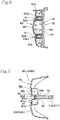
- FIG. 5 which is a sectional view along line V-V in FIG. 4 , is a sectional view obtained by cutting the V-belt-type continuously variable transmission T by the virtual plane Li.
- the drive pulley 40 on the front side and the driven pulley 47 on the rear side are located at the same position with respect to the vehicle width direction because the V-belt 44 is stretched therebetween.
- the centrifugal clutch 50 is located on the left side relative to the driven pulley 47.
- the case cover rear part 60r covering the centrifugal clutch 50 bulges outward in the vehicle width direction relative to the case cover front part 60f covering the drive pulley 40 and the cooling fan 43 (see FIG. 5 ).
- the case cover front part 60f covering the drive pulley 40 from the left side in the transmission case cover 60 includes an upper edge extending part 60fu and a lower edge extending part 60fl that extend rearward from the upper and lower parts of the case cover front part 60f toward the case cover central part 60c along the upper and lower side edges of the case cover central part 60c.
- the case cover front part 60f and the upper and lower edge extending parts 60fu and 60fl form an innermost region 60A (part provided with the finest lattice hatch in FIG. 8 ) that is on the innermost side in the vehicle width direction.
- case cover rear part 60r covering the centrifugal clutch 50 from the left side in the transmission case cover 60 and upper and lower extending parts 60ru and 60rl that bifurcate forward from the case cover rear part 60r into upper and lower parts and extend toward the case cover central part 60c form an outermost region 60D (part that is not provided with a hatch in FIG. 8 ) that is on the left outermost side in the vehicle width direction.
- the case cover central part 60c between the case cover front part 60f and the case cover rear part 60r in the transmission case cover 60 is fitted in such a manner that the upper and lower edge extending parts 60fu and 60fl of the innermost region 60A sandwich the front-end tapered parts of the upper and lower extending parts 60ru and 60rl of the outermost region 60D from the upper and lower sides.
- a fitting recess part 60v that is inwardly concave in the vehicle width direction is formed between the upper extending part 60ru and the lower extending part 60rl that bifurcate forward from the case cover rear part 60r of the outermost region 60D.
- the fitting recess part 60v formed between the upper extending part 60ru and the lower extending part 60rl is located at such a position as to straddle the virtual plane Li in the upward-downward direction and is formed into a tapered shape gradually decreasing in vertical width toward the rear side.
- the recessing depth position (position in the vehicle width direction) of the recess part is different between front and rear parts thereof. More specifically, the depth positions in the vehicle width direction of a front recess region 60B (part provided with a coarser lattice hatch than the innermost region 60A in FIG. 8 ) on the front side and of a rear recess region 60C (part provided with a coarser lattice hatch than the front recess region 60B in FIG. 8 ) on the rear side are both located between the innermost region 60A and the outermost region 60D.
- the innermost region 60A, the front recess region 60B, the rear recess region 60C, and the outermost region 60D are located on the left outside in the vehicle width direction in that order from the inner side to the outer side (see FIG. 5 ).
- a rim projecting rib 62 forming a rim is provided to have a shape of a circular ring around the cooling wind inlet 61.
- Screw holes are formed in the cylindrical attaching boss parts 63.
- a central cylindrical attaching boss part 64 is formed to protrude toward the inside in the vehicle-width direction (right side) (see FIGS. 5 and 8 ).
- the central cylindrical attaching boss part 64 slightly protrudes to the outside in the vehicle-width direction (left side).
- plural attaching boss parts 65 are formed to join the transmission case cover 60 to the transmission case 21T.
- a wind-guide duct cover 80 covers the innermost region 60A, the front recess region 60B, and the rear recess region 60C excluding the outermost region 60D in such a transmission case cover 60 from the outer lateral side in the vehicle width direction.
- the case cover front part 60f including the cooling wind inlet 61 in the transmission case cover 60 is covered by the wind-guide duct cover 80 from the outside with the intermediary of an inside duct member 70 therebetween.
- cylindrical attaching boss parts 73 into which the cylindrical attaching boss parts 63 are fitted are formed to protrude toward the outside in the vehicle-width direction (left side).
- the end parts of the cylindrical attaching boss parts 73 have bottom walls 73b having a ring shape.
- the wind-guide recess rib 75 runs around approximately three quarters of the outer circumference of the circular hole 71 from the upper part to the front part, the lower part, and the rear part sequentially and then extends upward, with the obliquely upper rear side of the circular hole 71 opened. Then, the wind-guide recess rib 75 bends and runs forward along the upper edge part of the upward-bulging part 70b and bends along the front edge part to extend downward.
- the wind-guide duct cover 80 has a duct cover rear part 80r extending rearward from the duct cover front major part 80f.
- a duct cover rear recess part 80rd is formed to be slightly hollow toward the inside in the vehicle-width direction (right side) (see FIG. 3 ).
- the hollow of the duct cover rear recess part 80rd in this duct cover rear part 80r may be absent.
- a ring-shaped bottom wall 83b at the end part of the protruding attaching cylindrical part 83 abuts against the ring-shaped bottom wall 73b of the opposing cylindrical attaching boss part 73.
- the ring-shaped bottom wall 83b at the end part of the attaching cylindrical part 83 forms the bottom surface of the bolt insertion recess part 83d and serves as a fastening seat face 83bs of a fastening bolt 91.
- the duct cover rear part 80r of the wind-guide duct cover 80 at its part where the duct cover rear recess part 80rd is located, is formed with a central attaching cylindrical part 84 protruding rightward and forming therein a bolt insertion recess part 84d depressed toward the inside in the vehicle-width direction (right side), to be opposed to the central cylindrical attaching boss part 64 protruding in the front recess region 60B of the transmission case cover 60.
- a wind-guide projecting rib 85 is formed to protrude to be opposed to the wind-guide recess rib 75 formed on the left side surface of the inside duct member 70.
- an external air intake 81 is opened at a position close to the front side.
- the external air intake 81 is provided with a louver 82 that guides external air and prevents entry of foreign matters.
- the whole of the wind-guide duct cover 80 including the duct cover rear part 80r is formed of a colored synthetic resin.
- the transmission case cover 60 is first put on the transmission case 21T with mating surfaces on their peripheries made to match each other. Then, the attaching boss parts 65 formed on the outer circumferential edge of the transmission case cover 60 are fastened to the transmission case 21T by fastening bolts 90 to attach the transmission case cover 60 to the transmission case 21T.
- a screw hole is formed in the end surface of the attaching boss part 21b.
- the inside duct member 70 is overlapped with the case cover front part 60f of the transmission case cover 60 attached to the transmission case 21T in this manner.
- the wind-guide projecting rib 85 of the wind-guide duct cover 80 is fitted to the wind-guide recess rib 75 of the inside duct member 70 with the intermediary of a sealing member 78, and the duct cover rear part 80r of the wind-guide duct cover 80 is fitted to the fitting recess part 60v of the transmission case cover 60 to fit the wind-guide duct cover 80 to the inside duct member 70 and the transmission case cover 60.
- the duct cover front major part 80f and the external air intake part 80b cover the innermost region 60A of the transmission case cover 60 from the outside, and the duct cover rear part 80r is fitted to the fitting recess part 60v of the transmission case cover 60 and covers the front recess region 60B and the rear recess region 60C.
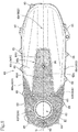
- parts that are not covered by the wind-guide duct cover 80 in the transmission case cover 60 are the outermost region 60D including the case cover rear part 60r, the upper extending part 60ru, and the lower extending part 60rl.
- the outermost region 60D serves as the case cover exposed region 60D exposed to the outside.
- case cover rear part 60r, the upper extending part 60ru, and the lower extending part 60rl serve as the rear exposed part 60r, the upper exposed part 60ru, and the lower exposed part 60rl, respectively (see FIG. 4 ).
- the bottom walls 83b of the three attaching cylindrical parts 83 of the wind-guide duct cover 80 each abut against the bottom wall 73b of the cylindrical attaching boss part 73 of the inside duct member 70, and the bottom wall 84b of the central attaching cylindrical part 84 of the wind-guide duct cover 80 abuts against the end part that slightly protrudes outward in the vehicle-width direction of the central cylindrical attaching boss part 64 of the transmission case cover 60.
- the bolt head of the fastening bolt 91 sinks in the bolt insertion recess part 83d and comes close to the screw hole of the cylindrical attaching boss part 63 of the transmission case cover 60.
- a short fastening bolt can be used.
- the bottom surface of the bolt insertion recess part 84d of the central attaching cylindrical part 84 serves as the fastening seat face 84bs of the fastening bolt 92, the head of the fastening bolt 92 sinks in the bolt insertion recess part 84d and comes close to the screw hole of the attaching boss part 21b of the transmission case 21T. Therefore, although the duct cover rear part 80r is co-fastened to the transmission case 21T together with the transmission case cover 60, a short fastening bolt can be used and the fastening can be carried out without protruding the fastening bolt outward in the vehicle-width direction.
- the wind-guide duct cover 80 is attached, with the inside duct member 70 interposed inside.
- the duct cover rear part 80r of the wind-guide duct cover 80 is fitted to the fitting recess part 60v located at such a position as to straddle the virtual plane Li of the transmission case cover 60 in the upward-downward direction.
- the duct cover rear part 80r is positioned in such an area as to straddle the virtual plane Li in the upward-downward direction.
- the duct cover rear part 80r of the wind-guide duct cover 80 is located in such an area as to straddle the virtual plane Li in the upward-downward direction and is fitted in the fitting recess part 60v of the transmission case cover 60.
- the protrusion of the duct cover rear part 80r to the outside in the vehicle width-direction is suppressed (see FIG. 3 and FIG. 7 ).
- the duct cover rear recess part 80rd that is recessed inward in the vehicle-width direction is formed in a region including the virtual plane Li in the duct cover rear part 80r, and the protrusion of the duct cover rear part 80r to the outside in the vehicle-width direction is further suppressed (see FIG. 3 and FIG. 7 ).
- the cooling fan 43 formed on the back surface of the fixed drive pulley half body 40a rotates due to the rotation of the crankshaft 20. External air is thereby taken in from the external air intake 81 opened in the external air intake part 80b of the wind-guide duct cover 80.
- the cooling wind taken in is guided in a wind-guide path formed by the fitting of the wind-guide projecting rib 85 of the wind-guide duct cover 80 and the wind-guide recess rib 75 of the inside duct member 70 and is introduced from the cooling wind introducing hole 71 and the cooling wind inlet 61 into the belt chamber 55 to cool the belt-type continuously variable transmission T in the belt chamber 55.
- the wind-guide duct cover 80 attached to cover mainly the front part of the transmission case cover 60 from the lateral side, has its duct cover rear part 80r which extends from the duct cover front major part 80f to the rear relative to the operation arm 33 when the main stand 30 is retracted.
- the saddle-type vehicle according to the present invention provides the advantageous effects described below.
- the operation arm 33 of the main stand 30 in the retracted state extends upward in a curved shape from the lower surface of the transmission case cover 60 along its left side surface and from the leg part 32 made to lie along the lower surface of the transmission case cover 60, at a position close to the rear side of the central part of the transmission case cover 60 in the front-rear direction, so that the foot-rest plate 33a on the tip of the operation arm 33 is located at such a position as to reach the vicinity of the upper edge of the transmission case cover 60.
- the duct cover rear part 80r of the wind-guide duct cover 80 that covers the transmission case cover 60 from the lateral side in the vehicle-width direction and is made of a synthetic resin is positioned to a rear-side position beyond the operation arm 33 when the main stand 30 is retracted. Therefore, the duct cover rear part 80r is disposed to cover the transmission case cover 60 in a region which the foot of the rider tends to hit when the rider puts the foot on the foot-rest plate 33a of the main stand 30 to erect the main stand 30. This prevents scratching of the transmission case cover made of metal at the time of erection operation of the main stand 30 and keeps the appearance of the transmission case good.
- the vicinity of the virtual plane Li including both the center axis lines of the front drive shaft (crankshaft 20) and the rear driven shaft (reducer input shaft 45) between which the belt of the belt-type continuously variable transmission T is stretched in the transmission case cover 60 is a region where the transmission case cover 60 bulges outward in the vehicle-width direction to the largest extent and thus is the region against which the rider's foot tends to hit.
- the co-fastening can be carried out by using the fastening bolt 92 of short length without protruding the fastening bolt 92 outward in the vehicle-width direction.
- the wind-guide duct cover 80 is formed with the duct cover rear part 80r extending to the rear side from the duct cover front major part 80f covering the front part of the transmission case cover 60.
- the duct cover front major part 80f and the duct cover rear part 80r are formed integrally and continuously in the wind-guide duct cover 80.
- the number of parts is reduced and assembling work and so forth are made easy.
- the wind-guide duct cover 80 made of synthetic resin is made by integrally forming the duct cover front major part 80f and the duct cover rear part 80r.
- a second embodiment will be described below, in which a duct cover rear part is divided from a duct cover front major part and is formed as a separate body.
- the components other than the wind-guide duct cover are the same as the power unit P according to the first embodiment and therefore the same numerals are also used.
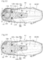
- FIG. 12 A left side view of a power unit P1 of a first example of the second embodiment is depicted in FIG. 12 .
- the dividing end surfaces 100fe and 100re of the duct cover front major part 100f and the duct cover rear part 100r are shaped to mutually form an angle and extend rearward from upper and lower intersections at which the upper and lower edges of the duct cover rear part 100r intersect the duct cover front major part 100f.
- the duct cover front major part 100f is fastened to the transmission case cover 60 by three fastening bolts 91.
- the duct cover rear part 100r is fitted to the fitting recess part 60v of the transmission case cover 60 and is fastened to the transmission case 21T together with the transmission case cover 60 through co-fastening by the fastening bolt 92.
- a wind-guide duct cover 110 of a power unit P2 of this second example is made of a colored synthetic resin.
- a duct cover rear part 110r is disposed to be away rearward and be separated from a duct cover front major part 110f.
- the duct cover front major part 110f is integrally formed with an external air intake part 110b, an upper edge extending part 110fu, and a lower edge extending part 110fr, which have the same shapes as the duct cover front major part 100f, the external air intake part 100b, the upper edge extending part 100fu, and the lower edge extending part 100fr in the first example.
- the duct cover rear part 110r has a shape resulting from the rearward displacement of the dividing end surface 100re of the duct cover rear part 100r of the first example.
- the duct cover front major part 110f and the duct cover rear part 110r are disposed in such a manner that the dividing end surface 110re forming an angle in a recessed shape in the duct cover rear part 110r is separated rearward from the dividing end surface 110fe forming an angle in a protruding shape in the duct cover front major part 110f.
- the duct cover front major part 110f is fastened to the transmission case cover 60 by three fastening bolts 91.
- the duct cover rear part 110r is fitted in the fitting recess part 60v of the transmission case cover 60 and is fastened to the transmission case 21T together with the transmission case cover 60 through co-fastening by the fastening bolt 92.
- the duct cover front major part 100f can be removed without removing the fastening bolt 92 with which the co-fastening is made.
- maintainability in carrying out maintenance or the like is improved.
- the duct cover rear part 120r has substantially the same shape as the duct cover rear part 120r of the first example depicted in FIG. 12 .
- an extending part 120ff extends rearward to provide a dividing end surface 120fe forming an angle in a rearwardly protruding manner, and the rear end surface of the extending part 120ff is the dividing end surface 120fe.
- the duct cover rear part 120r is fitted in the fitting recess part 60v of the transmission case cover 60 and is fastened to the transmission case 21T together with the transmission case cover 60 through co-fastening by the fastening bolt 92. Thereafter, the duct cover front major part 120f is fastened to the transmission case cover 60 by three fastening bolts 91, with the rearwardly extending part 120ff overlapped with the front end part of the duct cover rear part 120r from the outside in the vehicle-width direction.
- the duct cover front major part 100f can thus be removed without removing the fastening bolt 92 with which the co-fastening is made, and maintainability in carrying out maintenance or the like is improved.
Landscapes
- Engineering & Computer Science (AREA)
- Mechanical Engineering (AREA)
- General Engineering & Computer Science (AREA)
- Chemical & Material Sciences (AREA)
- Combustion & Propulsion (AREA)
- Transportation (AREA)
- General Details Of Gearings (AREA)
- Axle Suspensions And Sidecars For Cycles (AREA)
- Arrangement Of Transmissions (AREA)
- Arrangement Or Mounting Of Propulsion Units For Vehicles (AREA)
- Cooling, Air Intake And Gas Exhaust, And Fuel Tank Arrangements In Propulsion Units (AREA)
Applications Claiming Priority (2)
| Application Number | Priority Date | Filing Date | Title |
|---|---|---|---|
| JP2015163764 | 2015-08-21 | ||
| PCT/JP2016/070969 WO2017033615A1 (ja) | 2015-08-21 | 2016-07-15 | 鞍乗型車両のパワーユニット |
Publications (3)
| Publication Number | Publication Date |
|---|---|
| EP3339076A1 true EP3339076A1 (de) | 2018-06-27 |
| EP3339076A4 EP3339076A4 (de) | 2018-12-19 |
| EP3339076B1 EP3339076B1 (de) | 2020-05-20 |
Family
ID=58101263
Family Applications (1)
| Application Number | Title | Priority Date | Filing Date |
|---|---|---|---|
| EP16838962.5A Active EP3339076B1 (de) | 2015-08-21 | 2016-07-15 | Antriebseinheit für grätschsitzfahrzeug |
Country Status (5)
| Country | Link |
|---|---|
| EP (1) | EP3339076B1 (de) |
| JP (1) | JP6476301B2 (de) |
| CN (1) | CN107848411B (de) |
| BR (1) | BR112018002258B1 (de) |
| WO (1) | WO2017033615A1 (de) |
Families Citing this family (6)
| Publication number | Priority date | Publication date | Assignee | Title |
|---|---|---|---|---|
| US10889222B2 (en) * | 2018-11-08 | 2021-01-12 | Polaris Industries Inc. | Latching system for a vehicle seat |
| JP2020131839A (ja) * | 2019-02-15 | 2020-08-31 | 本田技研工業株式会社 | 車両の吸気ダクト構造 |
| JP6951390B2 (ja) * | 2019-09-06 | 2021-10-20 | 本田技研工業株式会社 | 変速機構 |
| JP7227200B2 (ja) * | 2020-08-18 | 2023-02-21 | 本田技研工業株式会社 | 鞍乗型車両のカバー構造 |
| JP7216128B2 (ja) * | 2021-02-16 | 2023-01-31 | 本田技研工業株式会社 | 吸気構造 |
| WO2025233957A1 (en) * | 2024-05-08 | 2025-11-13 | Tvs Motor Company Limited | A cover assembly for a transmission system of a vehicle |
Family Cites Families (7)
| Publication number | Priority date | Publication date | Assignee | Title |
|---|---|---|---|---|
| ES2157370T3 (es) * | 1995-06-29 | 2001-08-16 | Yamaha Motor Co Ltd | Transmision de variacion continua. |
| JP3518709B2 (ja) * | 1995-11-22 | 2004-04-12 | 本田技研工業株式会社 | 内燃機関の始動装置 |
| CN100484822C (zh) * | 2005-08-01 | 2009-05-06 | 雅马哈发动机株式会社 | 跨乘式车辆 |
| JP2007106382A (ja) * | 2005-10-17 | 2007-04-26 | Yamaha Motor Co Ltd | 自動二輪車 |
| JP2007278107A (ja) * | 2006-04-04 | 2007-10-25 | Yamaha Motor Co Ltd | 鞍乗型車両 |
| CN102483146B (zh) * | 2009-09-03 | 2015-07-15 | 本田技研工业株式会社 | V带式无极变速器的冷却风导入构造 |
| JP5147926B2 (ja) * | 2010-11-15 | 2013-02-20 | ヤマハ発動機株式会社 | 自動二輪車 |
-
2016
- 2016-07-15 EP EP16838962.5A patent/EP3339076B1/de active Active
- 2016-07-15 JP JP2017536679A patent/JP6476301B2/ja active Active
- 2016-07-15 WO PCT/JP2016/070969 patent/WO2017033615A1/ja not_active Ceased
- 2016-07-15 CN CN201680039836.XA patent/CN107848411B/zh active Active
- 2016-07-15 BR BR112018002258-6A patent/BR112018002258B1/pt active IP Right Grant
Also Published As
| Publication number | Publication date |
|---|---|
| CN107848411B (zh) | 2020-06-16 |
| BR112018002258B1 (pt) | 2022-11-29 |
| EP3339076B1 (de) | 2020-05-20 |
| CN107848411A (zh) | 2018-03-27 |
| JP6476301B2 (ja) | 2019-02-27 |
| BR112018002258A2 (pt) | 2018-09-18 |
| JPWO2017033615A1 (ja) | 2018-04-26 |
| WO2017033615A1 (ja) | 2017-03-02 |
| EP3339076A4 (de) | 2018-12-19 |
Similar Documents
| Publication | Publication Date | Title |
|---|---|---|
| EP3339076B1 (de) | Antriebseinheit für grätschsitzfahrzeug | |
| JP5997273B2 (ja) | 鞍乗型車両の吸気ダクト | |
| JP3154590U (ja) | 自動二輪車 | |
| US8157038B2 (en) | Saddle-ride type vehicle | |
| EP2610155B1 (de) | Grätschsitz-Fahrzeug | |
| JP3397274B2 (ja) | 自動二輪車の車体側部処理構造 | |
| US6397964B1 (en) | Scooter type vehicle | |
| JP5715844B2 (ja) | 自動二輪車における内燃機関下部の保護構造 | |
| JP6727250B2 (ja) | 鞍乗型車両の吸気構造 | |
| CN101249871B (zh) | 跨乘式车辆 | |
| JPH0913985A (ja) | エンジンのポンプ配置構造 | |
| JPH0911945A (ja) | 自動二輪車のシート装置 | |
| EP1375860B1 (de) | Brennkraftmaschine für ein Motorrad | |
| JP2009024555A (ja) | 内燃機関のブリーザ装置 | |
| JP3319673B2 (ja) | スクータ型自動二輪車の収納装置 | |
| JP3524219B2 (ja) | スクータ型自動二輪車の走行風導入構造 | |
| JP6951390B2 (ja) | 変速機構 | |
| JPH0911954A (ja) | 自動二輪車の車体カバー | |
| JP3319674B2 (ja) | 自動二輪車の冷却構造 | |
| JP2014104791A (ja) | 二輪車のvベルト式無段変速機の冷却装置 | |
| JP5521903B2 (ja) | ベルト式自動変速機の冷却構造 | |
| JPH0911959A (ja) | 動力ユニットの冷却装置 | |
| JP3501875B2 (ja) | 自動二輪車のスタンド装置 | |
| CA2498953C (en) | Four-cycle single-cylinder engine | |
| JP5172406B2 (ja) | 鞍乗り型車両のエンジン懸架構造 |
Legal Events
| Date | Code | Title | Description |
|---|---|---|---|
| STAA | Information on the status of an ep patent application or granted ep patent |
Free format text: STATUS: THE INTERNATIONAL PUBLICATION HAS BEEN MADE |
|
| PUAI | Public reference made under article 153(3) epc to a published international application that has entered the european phase |
Free format text: ORIGINAL CODE: 0009012 |
|
| STAA | Information on the status of an ep patent application or granted ep patent |
Free format text: STATUS: REQUEST FOR EXAMINATION WAS MADE |
|
| 17P | Request for examination filed |
Effective date: 20171121 |
|
| AK | Designated contracting states |
Kind code of ref document: A1 Designated state(s): AL AT BE BG CH CY CZ DE DK EE ES FI FR GB GR HR HU IE IS IT LI LT LU LV MC MK MT NL NO PL PT RO RS SE SI SK SM TR |
|
| AX | Request for extension of the european patent |
Extension state: BA ME |
|
| DAV | Request for validation of the european patent (deleted) | ||
| DAX | Request for extension of the european patent (deleted) | ||
| A4 | Supplementary search report drawn up and despatched |
Effective date: 20181119 |
|
| RIC1 | Information provided on ipc code assigned before grant |
Ipc: B62J 13/00 20060101ALI20181113BHEP Ipc: B62H 1/02 20060101ALI20181113BHEP Ipc: F16H 57/04 20100101ALI20181113BHEP Ipc: B60K 17/06 20060101AFI20181113BHEP Ipc: B60K 17/00 20060101ALI20181113BHEP |
|
| RIC1 | Information provided on ipc code assigned before grant |
Ipc: F16H 57/04 20100101ALI20190930BHEP Ipc: B60K 17/00 20060101ALI20190930BHEP Ipc: B62H 1/02 20060101ALI20190930BHEP Ipc: B60K 17/06 20060101AFI20190930BHEP Ipc: B62J 13/00 20060101ALI20190930BHEP |
|
| GRAP | Despatch of communication of intention to grant a patent |
Free format text: ORIGINAL CODE: EPIDOSNIGR1 |
|
| STAA | Information on the status of an ep patent application or granted ep patent |
Free format text: STATUS: GRANT OF PATENT IS INTENDED |
|
| INTG | Intention to grant announced |
Effective date: 20191203 |
|
| GRAS | Grant fee paid |
Free format text: ORIGINAL CODE: EPIDOSNIGR3 |
|
| GRAA | (expected) grant |
Free format text: ORIGINAL CODE: 0009210 |
|
| STAA | Information on the status of an ep patent application or granted ep patent |
Free format text: STATUS: THE PATENT HAS BEEN GRANTED |
|
| AK | Designated contracting states |
Kind code of ref document: B1 Designated state(s): AL AT BE BG CH CY CZ DE DK EE ES FI FR GB GR HR HU IE IS IT LI LT LU LV MC MK MT NL NO PL PT RO RS SE SI SK SM TR |
|
| REG | Reference to a national code |
Ref country code: GB Ref legal event code: FG4D |
|
| REG | Reference to a national code |
Ref country code: CH Ref legal event code: EP |
|
| REG | Reference to a national code |
Ref country code: DE Ref legal event code: R096 Ref document number: 602016036839 Country of ref document: DE |
|
| REG | Reference to a national code |
Ref country code: AT Ref legal event code: REF Ref document number: 1272387 Country of ref document: AT Kind code of ref document: T Effective date: 20200615 |
|
| REG | Reference to a national code |
Ref country code: LT Ref legal event code: MG4D |
|
| REG | Reference to a national code |
Ref country code: NL Ref legal event code: MP Effective date: 20200520 |
|
| PG25 | Lapsed in a contracting state [announced via postgrant information from national office to epo] |
Ref country code: PT Free format text: LAPSE BECAUSE OF FAILURE TO SUBMIT A TRANSLATION OF THE DESCRIPTION OR TO PAY THE FEE WITHIN THE PRESCRIBED TIME-LIMIT Effective date: 20200921 Ref country code: IS Free format text: LAPSE BECAUSE OF FAILURE TO SUBMIT A TRANSLATION OF THE DESCRIPTION OR TO PAY THE FEE WITHIN THE PRESCRIBED TIME-LIMIT Effective date: 20200920 Ref country code: FI Free format text: LAPSE BECAUSE OF FAILURE TO SUBMIT A TRANSLATION OF THE DESCRIPTION OR TO PAY THE FEE WITHIN THE PRESCRIBED TIME-LIMIT Effective date: 20200520 Ref country code: LT Free format text: LAPSE BECAUSE OF FAILURE TO SUBMIT A TRANSLATION OF THE DESCRIPTION OR TO PAY THE FEE WITHIN THE PRESCRIBED TIME-LIMIT Effective date: 20200520 Ref country code: SE Free format text: LAPSE BECAUSE OF FAILURE TO SUBMIT A TRANSLATION OF THE DESCRIPTION OR TO PAY THE FEE WITHIN THE PRESCRIBED TIME-LIMIT Effective date: 20200520 Ref country code: NO Free format text: LAPSE BECAUSE OF FAILURE TO SUBMIT A TRANSLATION OF THE DESCRIPTION OR TO PAY THE FEE WITHIN THE PRESCRIBED TIME-LIMIT Effective date: 20200820 Ref country code: GR Free format text: LAPSE BECAUSE OF FAILURE TO SUBMIT A TRANSLATION OF THE DESCRIPTION OR TO PAY THE FEE WITHIN THE PRESCRIBED TIME-LIMIT Effective date: 20200821 |
|
| PG25 | Lapsed in a contracting state [announced via postgrant information from national office to epo] |
Ref country code: BG Free format text: LAPSE BECAUSE OF FAILURE TO SUBMIT A TRANSLATION OF THE DESCRIPTION OR TO PAY THE FEE WITHIN THE PRESCRIBED TIME-LIMIT Effective date: 20200820 Ref country code: LV Free format text: LAPSE BECAUSE OF FAILURE TO SUBMIT A TRANSLATION OF THE DESCRIPTION OR TO PAY THE FEE WITHIN THE PRESCRIBED TIME-LIMIT Effective date: 20200520 Ref country code: RS Free format text: LAPSE BECAUSE OF FAILURE TO SUBMIT A TRANSLATION OF THE DESCRIPTION OR TO PAY THE FEE WITHIN THE PRESCRIBED TIME-LIMIT Effective date: 20200520 Ref country code: HR Free format text: LAPSE BECAUSE OF FAILURE TO SUBMIT A TRANSLATION OF THE DESCRIPTION OR TO PAY THE FEE WITHIN THE PRESCRIBED TIME-LIMIT Effective date: 20200520 |
|
| REG | Reference to a national code |
Ref country code: AT Ref legal event code: MK05 Ref document number: 1272387 Country of ref document: AT Kind code of ref document: T Effective date: 20200520 |
|
| PG25 | Lapsed in a contracting state [announced via postgrant information from national office to epo] |
Ref country code: AL Free format text: LAPSE BECAUSE OF FAILURE TO SUBMIT A TRANSLATION OF THE DESCRIPTION OR TO PAY THE FEE WITHIN THE PRESCRIBED TIME-LIMIT Effective date: 20200520 Ref country code: NL Free format text: LAPSE BECAUSE OF FAILURE TO SUBMIT A TRANSLATION OF THE DESCRIPTION OR TO PAY THE FEE WITHIN THE PRESCRIBED TIME-LIMIT Effective date: 20200520 |
|
| PG25 | Lapsed in a contracting state [announced via postgrant information from national office to epo] |
Ref country code: EE Free format text: LAPSE BECAUSE OF FAILURE TO SUBMIT A TRANSLATION OF THE DESCRIPTION OR TO PAY THE FEE WITHIN THE PRESCRIBED TIME-LIMIT Effective date: 20200520 Ref country code: SM Free format text: LAPSE BECAUSE OF FAILURE TO SUBMIT A TRANSLATION OF THE DESCRIPTION OR TO PAY THE FEE WITHIN THE PRESCRIBED TIME-LIMIT Effective date: 20200520 Ref country code: DK Free format text: LAPSE BECAUSE OF FAILURE TO SUBMIT A TRANSLATION OF THE DESCRIPTION OR TO PAY THE FEE WITHIN THE PRESCRIBED TIME-LIMIT Effective date: 20200520 Ref country code: RO Free format text: LAPSE BECAUSE OF FAILURE TO SUBMIT A TRANSLATION OF THE DESCRIPTION OR TO PAY THE FEE WITHIN THE PRESCRIBED TIME-LIMIT Effective date: 20200520 Ref country code: AT Free format text: LAPSE BECAUSE OF FAILURE TO SUBMIT A TRANSLATION OF THE DESCRIPTION OR TO PAY THE FEE WITHIN THE PRESCRIBED TIME-LIMIT Effective date: 20200520 Ref country code: CZ Free format text: LAPSE BECAUSE OF FAILURE TO SUBMIT A TRANSLATION OF THE DESCRIPTION OR TO PAY THE FEE WITHIN THE PRESCRIBED TIME-LIMIT Effective date: 20200520 Ref country code: ES Free format text: LAPSE BECAUSE OF FAILURE TO SUBMIT A TRANSLATION OF THE DESCRIPTION OR TO PAY THE FEE WITHIN THE PRESCRIBED TIME-LIMIT Effective date: 20200520 |
|
| REG | Reference to a national code |
Ref country code: DE Ref legal event code: R119 Ref document number: 602016036839 Country of ref document: DE |
|
| PG25 | Lapsed in a contracting state [announced via postgrant information from national office to epo] |
Ref country code: PL Free format text: LAPSE BECAUSE OF FAILURE TO SUBMIT A TRANSLATION OF THE DESCRIPTION OR TO PAY THE FEE WITHIN THE PRESCRIBED TIME-LIMIT Effective date: 20200520 Ref country code: MC Free format text: LAPSE BECAUSE OF FAILURE TO SUBMIT A TRANSLATION OF THE DESCRIPTION OR TO PAY THE FEE WITHIN THE PRESCRIBED TIME-LIMIT Effective date: 20200520 Ref country code: SK Free format text: LAPSE BECAUSE OF FAILURE TO SUBMIT A TRANSLATION OF THE DESCRIPTION OR TO PAY THE FEE WITHIN THE PRESCRIBED TIME-LIMIT Effective date: 20200520 |
|
| REG | Reference to a national code |
Ref country code: CH Ref legal event code: PL |
|
| PLBE | No opposition filed within time limit |
Free format text: ORIGINAL CODE: 0009261 |
|
| STAA | Information on the status of an ep patent application or granted ep patent |
Free format text: STATUS: NO OPPOSITION FILED WITHIN TIME LIMIT |
|
| 26N | No opposition filed |
Effective date: 20210223 |
|
| GBPC | Gb: european patent ceased through non-payment of renewal fee |
Effective date: 20200820 |
|
| REG | Reference to a national code |
Ref country code: BE Ref legal event code: MM Effective date: 20200731 |
|
| PG25 | Lapsed in a contracting state [announced via postgrant information from national office to epo] |
Ref country code: FR Free format text: LAPSE BECAUSE OF NON-PAYMENT OF DUE FEES Effective date: 20200720 Ref country code: LU Free format text: LAPSE BECAUSE OF NON-PAYMENT OF DUE FEES Effective date: 20200715 Ref country code: LI Free format text: LAPSE BECAUSE OF NON-PAYMENT OF DUE FEES Effective date: 20200731 Ref country code: CH Free format text: LAPSE BECAUSE OF NON-PAYMENT OF DUE FEES Effective date: 20200731 |
|
| PG25 | Lapsed in a contracting state [announced via postgrant information from national office to epo] |
Ref country code: SI Free format text: LAPSE BECAUSE OF FAILURE TO SUBMIT A TRANSLATION OF THE DESCRIPTION OR TO PAY THE FEE WITHIN THE PRESCRIBED TIME-LIMIT Effective date: 20200520 Ref country code: BE Free format text: LAPSE BECAUSE OF NON-PAYMENT OF DUE FEES Effective date: 20200731 Ref country code: DE Free format text: LAPSE BECAUSE OF NON-PAYMENT OF DUE FEES Effective date: 20210202 |
|
| PG25 | Lapsed in a contracting state [announced via postgrant information from national office to epo] |
Ref country code: GB Free format text: LAPSE BECAUSE OF NON-PAYMENT OF DUE FEES Effective date: 20200820 Ref country code: IE Free format text: LAPSE BECAUSE OF NON-PAYMENT OF DUE FEES Effective date: 20200715 |
|
| PG25 | Lapsed in a contracting state [announced via postgrant information from national office to epo] |
Ref country code: TR Free format text: LAPSE BECAUSE OF FAILURE TO SUBMIT A TRANSLATION OF THE DESCRIPTION OR TO PAY THE FEE WITHIN THE PRESCRIBED TIME-LIMIT Effective date: 20200520 Ref country code: MT Free format text: LAPSE BECAUSE OF FAILURE TO SUBMIT A TRANSLATION OF THE DESCRIPTION OR TO PAY THE FEE WITHIN THE PRESCRIBED TIME-LIMIT Effective date: 20200520 Ref country code: CY Free format text: LAPSE BECAUSE OF FAILURE TO SUBMIT A TRANSLATION OF THE DESCRIPTION OR TO PAY THE FEE WITHIN THE PRESCRIBED TIME-LIMIT Effective date: 20200520 |
|
| PG25 | Lapsed in a contracting state [announced via postgrant information from national office to epo] |
Ref country code: MK Free format text: LAPSE BECAUSE OF FAILURE TO SUBMIT A TRANSLATION OF THE DESCRIPTION OR TO PAY THE FEE WITHIN THE PRESCRIBED TIME-LIMIT Effective date: 20200520 |
|
| PGFP | Annual fee paid to national office [announced via postgrant information from national office to epo] |
Ref country code: IT Payment date: 20250619 Year of fee payment: 10 |