EP3339538B1 - Ébauche de clé pour fabrication d'un clé pour une serrure cylindrique, clé, dispositif de fermeture et procédure - Google Patents
Ébauche de clé pour fabrication d'un clé pour une serrure cylindrique, clé, dispositif de fermeture et procédure Download PDFInfo
- Publication number
- EP3339538B1 EP3339538B1 EP18164763.7A EP18164763A EP3339538B1 EP 3339538 B1 EP3339538 B1 EP 3339538B1 EP 18164763 A EP18164763 A EP 18164763A EP 3339538 B1 EP3339538 B1 EP 3339538B1
- Authority
- EP
- European Patent Office
- Prior art keywords
- key
- recess
- longitudinal direction
- broad side
- side faces
- Prior art date
- Legal status (The legal status is an assumption and is not a legal conclusion. Google has not performed a legal analysis and makes no representation as to the accuracy of the status listed.)
- Active
Links
Images






Classifications
-
- E—FIXED CONSTRUCTIONS
- E05—LOCKS; KEYS; WINDOW OR DOOR FITTINGS; SAFES
- E05B—LOCKS; ACCESSORIES THEREFOR; HANDCUFFS
- E05B19/00—Keys; Accessories therefor
- E05B19/0017—Key profiles
- E05B19/0023—Key profiles characterized by variation of the contact surface between the key and the tumbler pins or plates
-
- E—FIXED CONSTRUCTIONS
- E05—LOCKS; KEYS; WINDOW OR DOOR FITTINGS; SAFES
- E05B—LOCKS; ACCESSORIES THEREFOR; HANDCUFFS
- E05B19/00—Keys; Accessories therefor
- E05B19/0017—Key profiles
- E05B19/0029—Key profiles characterized by varying cross-sections of different keys within a lock system
-
- E—FIXED CONSTRUCTIONS
- E05—LOCKS; KEYS; WINDOW OR DOOR FITTINGS; SAFES
- E05B—LOCKS; ACCESSORIES THEREFOR; HANDCUFFS
- E05B27/00—Cylinder locks or other locks with tumbler pins or balls that are set by pushing the key in
- E05B27/0003—Details
- E05B27/0017—Tumblers or pins
-
- E—FIXED CONSTRUCTIONS
- E05—LOCKS; KEYS; WINDOW OR DOOR FITTINGS; SAFES
- E05B—LOCKS; ACCESSORIES THEREFOR; HANDCUFFS
- E05B35/00—Locks for use with special keys or a plurality of keys ; keys therefor
- E05B35/003—Locks for use with special keys or a plurality of keys ; keys therefor for keys with movable bits
Definitions
- the present invention relates to a key blank for producing a key for a lock cylinder, the key blank having a shaft extending along a longitudinal direction, the shaft having an, in particular essentially rectangular, cross section perpendicular to the longitudinal direction, the cross section having two wider broad side surfaces and has two narrower narrow side surfaces.
- the present invention also relates to a key for a lock cylinder, a device with a lock cylinder and a key, and a method for producing a key.
- the document shows WO 2014/032191 A1 a blank for the production of a security key with at least two coding / tumbler rows on the flat sides of the key for an associated cylinder with tumblers and counter tumblers. Furthermore, a security key with at least two coding / tumbler rows on the flat sides of the key for an assigned cylinder with tumblers and counter-tumblers is shown.
- the publication also shows DE 10 2015 111 914 A1 a key for a lock cylinder, wherein the key has a key shaft extending along a longitudinal direction with two opposite key broad side surfaces, the key shaft having a recess through the key broad side surfaces, wherein a shaft extends through the recess, and wherein the shaft rotatably in the key shaft is arranged, and wherein in the recess at least two rings are arranged on the shaft next to one another, wherein an inner diameter of each ring is greater than an outer diameter of the shaft.
- Such keys are made from pre-produced key blanks. In general, efforts are made to keep the production costs as low as possible.
- the publication also shows WO 2008/139475 A2 an improved key blank with movable elements and an improved lock.
- the publication also shows WO 2009/147660 A2 a key, a lock and a locking mechanism.
- the publication also shows WO 2004/048724 A1 a backwards compatible lock system, as well as key blanks and keys for it.
- the publication also shows WO 2008/015672 A2 an improved locking device.
- the publication also shows DE 209 18 143 U1 a security key.
- a key blank for producing a key for a lock cylinder having a shaft extending along a longitudinal direction, the shaft having a particularly substantially rectangular cross-section perpendicular to the longitudinal direction, the Cross-section has two wider broad side surfaces and two narrower narrow side surfaces, the key blank being a reversible key blank, the shaft having a recess with a rectangular bottom surface in each of the broad side surfaces, with a thickness of the key blank between the bottom surfaces of the recesses being less than 1.8 mm.
- Such a key blank which is intended for use in the production of a reversible key, generally has a key rail, that is to say a handle or holding section, and an adjoining key shaft extending along the longitudinal direction. This key shaft is then provided for insertion into a lock cylinder.
- the key shaft has a substantially rectangular shape in cross section. This results in two wider or longer sides and two narrower or shorter sides in cross section. The two longer or wider sides are called broad side surfaces here. In the prior art, these broad side surfaces are also referred to as flat sides.
- At least one longitudinally extending first rib and one longitudinally extending second rib are arranged on each of the broadside surfaces, the first rib in a direction parallel to the broadside surfaces and perpendicular to the longitudinal direction wider than the second rib.
- a blank can be provided via which suitable key profiles can be generated in the longitudinal direction by means of the ribs and milling processes.
- each of the recesses is arranged between the respective first rib and the second rib. In this way, ribs and recess contours, in particular in a cross section perpendicular to the longitudinal direction, can be used to query suitable pin contours and can interact.
- a side surface of the recess extending parallel to the longitudinal direction is arranged adjacent to the first rib and the recess is open towards the second rib.
- the recess of the key blank has three side surfaces.
- a recess in a rectangular bottom surface is provided in each of the broad side surfaces.
- a thickness of the key blank between the bottom surfaces should be less than 1.8 mm. In particular, the thickness can be less than 1.6 mm, further in particular less than 1.4 mm.
- such a key blank can be used for several key types or locking systems.
- the recess can be used to query a pin tumbler, as is explained in the context of the present application.
- provision can also be made, for example, to remove the remaining material thickness of less than 1.8 mm and to provide a recess by means of the recesses, into which, for example, ring elements can then be inserted, as described in the document DE 10 2015 111 914 A1 is shown.
- a key for a lock cylinder having a shaft extending along a longitudinal direction, the shaft having an, in particular essentially rectangular, cross section perpendicular to the longitudinal direction, the cross section being two wider Broad side surfaces and two narrower narrow side surfaces, the key being a reversible key, the shaft having a recess with a rectangular bottom surface in each of the broad side surfaces, and wherein a thickness of the key between the bottom surfaces of the recesses is less than 1.8 mm, and the Recesses has three side surfaces which each extend from the respective broad side surface to the respective bottom surface, one of the side surfaces extending parallel to the longitudinal direction and two side surfaces extending perpendicular to the longitudinal direction.
- a key in which a recess can be used as a shaped element for querying a locking device, in particular a pin tumbler.
- a security key can be produced from the key blank according to the first aspect of the invention. After the key shank has been profiled, one of the side surfaces can be recessed towards a milled-out groove in the key profile. Due to the pre-stamping of the recess, no further milling work is necessary to produce the recess in the key.
- a pin tumbler can, for example, query the rectangular contour of the recess or the bottom surface or also further geometrical configurations of the recess and / or the bottom surface, as will be described below in configurations.
- each of the broad side surfaces at least one first rib extending in the longitudinal direction and a second rib extending in the longitudinal direction are arranged, the first rib in a direction parallel to the broad side surfaces and perpendicular to the The lengthwise direction is wider than the second rib.
- each of the recesses is arranged between the respective first rib and the second rib. In this way, ribs and recess contours, in particular in a cross section perpendicular to the longitudinal direction, can be used to query suitable pin contours and can interact.
- a side surface of the recess extending parallel to the longitudinal direction is arranged adjacent to the first rib and the recess is open towards the second rib.
- the recess of the key blank has three side surfaces.
- a locking device with a lock cylinder and a key according to the second aspect of the invention or one of its configurations
- the lock cylinder having a housing and a cylinder core
- the lock cylinder having a plurality of locking fuses, each locking fuse between a locked state and a release state is movable and a rotational movement of the cylinder core with respect to the housing in the locked state and releases in the released state, and wherein the lock cylinder can be converted from the locked state into the released state by fully inserting the key into a key channel of the cylinder core, and wherein the recess one of the locking devices is assigned.
- a locking device which uses the key according to the second aspect of the invention and wherein one of the locking fuses is assigned to the recess, so that it is used as a security-relevant query feature.
- a locking device can in particular be a pin tumbler.
- further locking fuses or pin tumblers for interrogating other features of a key can be provided in the locking device.
- a method for producing a key comprising the steps of providing a key blank according to the first aspect of the invention or one of its configurations, which involves forming a desired key profile by machining the shaft in the longitudinal direction; and the completion of the key by further machining, in particular wherein the completion comprises the introduction of recesses by means of drilling.
- This method enables two different key types, namely the first key or the second key, to be produced from a single type of key blank. In this way, production can be significantly simplified and made more cost-effective. It is not necessary to have two different key blanks. In this way, storage costs can be reduced.
- the bottom surfaces overlap each other in a direction perpendicular to the broad side surfaces.
- the overlap can be such that a bore guided perpendicularly through both broad side surfaces can run through both base surfaces.
- the key blank can be used for a first type of key.
- the key blank has a key rail from which the shaft extends, and wherein the recesses are arranged in a front third of the shaft facing away from the key rail.
- the shaft has a key tip facing away from the key rail, and a center of each recess is 5 mm to 8 mm, in particular 6 mm to 7 mm, away from the key tip.
- the first rib is twice as wide as the second rib, in particular wherein the first rib is less than or equal to 2 mm wide and the second rib is less than or equal to 1 mm wide.
- the rectangular bottom surface has a length parallel to the longitudinal direction of 1.5 mm to 2.5 mm, in particular a length of 2.12 mm.
- both ring elements for keys of the second type can be arranged and a suitable space for querying pin tumblers in keys of a first type can be provided.
- the rectangular bottom surface has a width in a direction parallel to the broad side surfaces and perpendicular to the longitudinal direction of 1.5 mm to 2.5 mm, in particular a width of 1.7 mm up to and including 2 , 1 mm.
- a central plane of each recess extending in the longitudinal direction is arranged with an offset to a central plane of the broad side surface extending in the longitudinal direction in which the respective recess is arranged.
- the key blank is a reversible key blank. Consequently, the recesses on the two broad side surfaces are either arranged symmetrically to the center plane, so that the reversible key is inevitably suitable. It is therefore also possible for the recesses to be arranged in the opposite direction with an offset to the center plane, so that a reversible key blank is retained. However, the recesses then do not overlap one another completely, but only partially. However, this can be sufficient for producing the recess by milling out the recesses. The offset can then be a further feature that can be queried by means of a pin tumbler.
- the offset amounts to 0.15 mm to 0.55 mm in each case.
- the offset can be 0.2 mm to 0.5 mm.
- the offset can be 0.22 mm or 0.42 mm.
- each of the recesses has at least three, in particular four, side surfaces, each extending from the respective broad side surface to the respective bottom surface, and each of the side surfaces at an angle to a plane perpendicular to the Broad side surfaces is inclined, each recess opening from the base surface to the broad side surface.
- each recess opens from the base line to the broadside surface, this means that the recess tapers, in other words, from the broadside surface towards the bottom surface.
- the recess therefore has no undercut.
- Each broad side surface can have the same angle with respect to the plane. However, the angles can in principle be different. In principle, it can also be provided that not all of the at least three, in particular four, side surfaces, but rather fewer side surfaces, have an angle different from 0 ° with respect to the plane.
- the angle is 5 ° to 15 °, in particular where the angle is 10 °.
- pins can easily slide in and out of the recess and, at the same time, a further safety feature can be provided.
- a pen then has to be a have a corresponding taper at its tip in order to slide down to the bottom surface can.
- each of the recesses has at least three, in particular four, side surfaces, each extending from the respective bottom surface to the respective broad side surface, and wherein at least one of the side surfaces merges with a radius into the respective broad side surface, in particular wherein two side surfaces running perpendicular to the longitudinal direction merge with the radius into the respective broad side surface. It is also possible for three or all four side surfaces with the radius to merge into the respective broad side surface.
- a pin can simply slide in or out of the recess. Furthermore, a further security feature can be provided by means of the radius, which must be fulfilled in a complementary manner by a pin.
- the radius is 0.2 mm to 0.6 mm in each case, in particular it can be 0.4 mm.
- a maximum thickness between the broad side surfaces is 2.4 mm to 2.8 mm, in particular the maximum thickness between the broad side surfaces being 2.6 mm.
- the bottom surface has a non-planar profile in a cross section perpendicular to the longitudinal direction.
- the profile can be stepped, inclined, curved and / or jagged.
- the bottom surface can therefore not be straight, but rather be inclined, stepped, curved, and / or jagged. Any non-planar profiling can be provided. In this way, a further security feature can be provided which has to be fulfilled by a pin that slides into the recess in order to completely immerse into the recess.
- the bottom surface has a geometric body which extends from the bottom surface in the direction of the broad side surface, in particular wherein the geometric body is a hemisphere, a cone, a cuboid or a cylinder. It can be any three-dimensional geometric body.
- a geometric configuration of the bottom surface of the recess can also be provided, which must be complementarily fulfilled by a pin element in order to be able to slide completely into the recess.
- a three-dimensional design can be created by means of a geometric body, which can additionally increase safety.
- each of the side surfaces is inclined at an angle with respect to a plane perpendicular to perpendicular to the broad side surfaces, and with each recess opening from the base surface towards the broad side surface.
- a further security feature can be provided by means of the inclination of the side surfaces.
- sliding a pin into or out of the recess can be simplified.
- the Side surfaces do not have an undercut. The cross-sectional area of the recess thus becomes larger from the bottom surface to the broad side surface.
- the angle is 5 ° to 15 °, in particular the angle being 10 °.
- At least one of the side surfaces merges with a radius into the respective broad side surface, in particular with two side surfaces running perpendicular to the longitudinal direction merging with the radius into the respective broad side surface. It is also possible for three or all four side surfaces with the radius to merge into the respective broad side surface.
- the radius can serve as a safety feature, so that a pin must have a correspondingly complementary radius in order to fully immerse into the recess.
- the radius is 0.2 mm to 0.6 mm, in particular 0.4 mm.
- the key blank it can be provided that at least one first extending in the longitudinal direction on each broad side surface Rib and a second rib extending in the longitudinal direction are arranged, the first rib perpendicular to the longitudinal direction being wider than the second rib.
- each of the recesses is arranged between the respective first rib and the second rib.
- the first rib is twice as wide as the second rib, in particular wherein the first rib is less than or equal to 2 mm wide and the second rib is less than or equal to 1 mm wide.
- the side surface of the recess extending parallel to the longitudinal direction is arranged adjacent to the first rib, and wherein the recess is open towards the second rib.
- a contour of the recess can be continued in a cross section perpendicular to the longitudinal direction by means of the second rib and can thus serve as a further security feature.
- the recess has a straight contour, a stepped contour or an inclined contour in a cross section of the key perpendicular to the longitudinal direction.
- the contour of the recess is to be distinguished from the above-described profile of the bottom surface in this cross section.
- the recess can be straight, oblique or inclined or stepped in cross section perpendicular to the longitudinal direction. In this way, however, a locking height of the pin tumbler can also be defined. It has been shown that sufficient blocking is provided with the specified dimensions.
- the bottom surface has a non-planar profile in a cross section perpendicular to the longitudinal direction.
- the profile can be stepped, inclined, curved and / or jagged.
- the bottom surface can be profiled in the cross section perpendicular to the longitudinal direction in such a way as to provide an additional safety feature that must be fulfilled by a tumbler or a pin of a pin tumbler.
- the bottom surface has a geometrical body which extends from the bottom surface in the direction of the broad side surface.
- the geometric body can be a hemisphere, a cone, a cuboid or a cylinder.
- the locking device assigned to the recess is designed as a pin tumbler.
- the pin tumbler can be an active spring-loaded pin tumbler.
- the recess can be used advantageously as a locking device, in particular with a pin tumbler.
- a pin tumbler pretensioned into the recess by means of a spring can be used advantageously.
- a core pin must then have a geometry in which it can plunge completely into the recess in order to bring the locking device into the release state.
- the locking device assigned to the recess has a housing pin and a core pin, the core pin having a bearing surface facing away from the housing pin, and wherein the bearing surface is arranged in the recess in the released state.
- the core pin must be able to completely immerse into the recess in order to be arranged in the release state.
- the contact surface can rest on the floor surface.
- the support surface can also be spaced apart from the base surface in the released state and the core pin can come to rest against the cylinder core on another surface designed for this purpose, for example a circumferential collar surface outside a closing channel of the cylinder core.
- the core pin has a run-on slope in both directions parallel to the longitudinal direction.
- a profile of the support surface of the core pin in a cross section perpendicular to the longitudinal direction is complementary to a profile of the bottom surface in the cross section in the released state.
- the core pin must therefore have a support surface that is designed to be complementary to the bottom surface of the recess in order to completely immerse into the recess and bring the display surface completely with the bottom surface system.
- the bottom surface of the recess has a geometric body which extends from the bottom surface in the direction of the broad side surface, in particular wherein the geometric body is a hemisphere, a cone, a cuboid or a cylinder, and wherein the Support surface of the core pin has a recess which is designed to be complementary to the geometric body.
- At least two rings are arranged side by side on the shaft.
- the rings are each arranged directly next to one another.
- “Side by side” means that the rings are arranged adjacent, in particular directly adjacent, to one another. There are therefore no sleeve elements, spacers or other elements between the rings.
- the rings can rest against one another. It goes without saying that a certain amount of play is maintained in order to enable rotation of the rings relative to one another or a translational movement of the rings relative to one another.
- the at least two rings are arranged next to one another on the common shaft. Due to the configuration according to the invention, the rings can be independent of one another rotate on the shaft. Furthermore, the rings can be moved independently of one another perpendicular to a longitudinal axis of the shaft. This is made possible because the inside diameter is larger than the outside diameter of the shaft. The amount by which a ring can be moved perpendicular to the longitudinal axis of the shaft is measured by how much larger the inner diameter of the ring is than the outer diameter of the shaft. In particular, the inner diameter of the ring can be 1.25 times the outer diameter of the shaft, in particular 1.5 times, in particular 2 times, in particular 2.5 times.
- a step of forming a desired key profile by machining the shaft in the longitudinal direction is carried out.
- At least the step of providing is carried out at a first production site, and that at least the step of finishing is carried out at a second production site.
- Fig. 1 shows an embodiment of a key blank 10.
- the key blank 10 has a key rail 12 and a key shank 14.
- the key shaft 14 extends starting from the key rail 12 in a longitudinal direction that is in the Fig. 1 is designated by X or the reference numeral 11.
- a transverse direction denoted by Y extends perpendicular to this longitudinal direction.
- the direction Z is perpendicular to X and Y. Together, the axes of the directions X, Y and Z form a Cartesian coordinate system.
- the plane YZ is perpendicular to the longitudinal direction X. In this direction, for example, the cross section IV-IV is Fig. 4 shown.
- the cross section III-III of the Fig. 3 is shown in plane XZ.
- the key shaft 14 has a cross-sectional shape that is essentially rectangular in the Y-Z plane.
- the two narrower sides of the rectangle are denoted by the reference symbol 16 and are referred to as narrow sides.
- the longer sides of the rectangle are denoted by the reference symbols 18 or 18 'and are referred to below as broad side surfaces. These broad side surfaces are also referred to as flat sides in other terminologies.
- a tip of the shaft 14 facing away from the key rail 12 is designated by the reference number 22.
- the key blank has two ribs 24 and 26 on the shaft.
- the rib 24 is shown wider than the rib 26.
- the rib 24 is also referred to as the first rib.
- the rib 26 is also referred to as the second rib.
- the first rib 24 can be designed with a width of 2 mm.
- the second rib 26 can be formed with a width of 1 mm.
- Corresponding ribs are formed.
- the key blank 10 is designed as a reversible key blank with corresponding axial symmetry of the shaft along its longitudinal axis 29, which runs parallel to the longitudinal direction, compare this Fig. 4 .
- a recess 28 is arranged on each of the broad side surfaces 18, 18 '.
- the recess 28 is formed between the ribs 24 and 26 in the illustrated embodiments.
- the recess 28 is explained in more detail below.
- the recess has a rectangular shape and a rectangular bottom surface.
- the recess 28 is arranged in the front third of the key shaft 14.
- FIG. 10 shows a top view of the key blank 10 of FIG Fig. 1 .
- a distance 46 from a center 45 of the recess 28 to the key tip 22 is shown.
- the distance 46 can be 5 to 8 mm, in particular 6 to 7 mm.
- FIG. 3 is a cross-sectional view taken along line III-III in FIG Fig. 2 shown.
- a thickness of the key blank which is denoted by 48, is between 2.4 and 2.8 mm, in particular it can be 2.6 mm.
- the thickness of the key blank between the bottom surfaces, which is designated by 34, is less than 1.8 mm, in particular less than 1.5 mm, in particular less than 1.4 mm.
- a length of the recess 28 in the longitudinal direction ie within the Fig. 3
- the sectional plane shown is in a range from 1.5 mm up to and including 2.5 mm, in particular the longitudinal can be 2.12 mm.
- a width of the recess 28 can be 1.5 mm to 2.5 mm, in particular from 1.7 to and including 2.1 mm.
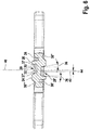
- the side surfaces of the recess which run perpendicular to the longitudinal direction, are at 39 and 39 'in the Fig. 3 designated. They are inclined with respect to a plane perpendicular to the longitudinal direction by an angle which is denoted by the reference symbol 35. This angle 35 is 5 ° to 15 °, in particular it can be 10 °.
- a bottom surface of the recess 28 is denoted by the reference symbol 32.
- a bottom surface of the recess 28 ' is denoted by the reference numeral 32'.
- the Fig. 4 shows a section perpendicular to the longitudinal direction.
- the side surfaces which run parallel to the longitudinal direction are denoted by 37 and 37 ', respectively. These are inclined by an angle designated by reference numeral 36 with respect to a plane along the longitudinal direction which is perpendicular to the broad side surfaces 18, 18 '. This angle can also be 5 ° to 15 °, in particular 10 °.
- the angles 35 and 36 can be identical but also different.
- the recesses 28, 28 ' are arranged due to the design of the key blank 10 as a reversible key blank in such a way that they overlap one another.
- the recesses 28, 28 ' can be symmetrical to a center of the key blank, ie symmetrical to the cutting plane of the Fig. 3 be arranged. However, this does not necessarily have to be the case. They can also be arranged with an offset, as described in connection with the Fig. 6 will be explained.
- a key of a first type which interrogates the recesses 28, 28 'by means of a locking tumbler.
- movable elements can also be arranged in a recess, which is formed by milling out the remaining thickness of the key or the key blank between the recesses 28, 28 ', in order to produce a key of a second type.
- the Fig. 21 shows schematically the arrangement of two rings 98, 98 ′ as movable elements on a shaft 99 within a recess produced in this way through the broad side surface 18, 18 ′ of the key blank 10.
- the Fig. 5 shows a key 58, which can be made from the key blank 10, for example.
- the key also has the recess 28.
- a profile 38 is formed in the key by longitudinal grooves straight to the longitudinal direction X, for example cut or milled. In principle, however, such a profile can also already be formed in the key blank 10.
- the key has bores 56 in the broad side surfaces as well as in the narrow side surfaces, which are queried by pins of a lock cylinder.
- FIG. 6 shows a section along a line VI-VI of FIG Fig. 5 .
- a central plane 40 of the key 58 is shown.
- the key blank 10 also has the corresponding central plane.
- the center of the recess 28 ′ is designated by 42.
- the recess 28 ′ has an offset 44 to the center 40.
- the offset can be between 0.15 mm and 0.55 mm. In particular, the offset can be 0.22 mm or 0.42 mm.
- Fig. 6 In the illustrated embodiment and the view of Fig. 6 is the offset of the recess 28 'to the left of the plane 40.
- the recess 28 is offset in the opposite direction from the center 40 to the right and the same offset 44. This is necessary due to the design of the key as a reversible key or the key blank as a reversible key blank.
- the recesses do not completely overlap. However, the recesses still overlap to such an extent that the creation of the recess is still significantly simplified.
- Profile grooves cut along the longitudinal direction X are indicated schematically by 38, 38 ', 38 "and 38'".
- the side surfaces 39 and 39 ' ie those side surfaces which run perpendicular to the central plane 40 or XZ plane, merge into the broad side surfaces 18, 18' by means of a radius, which can be removed for the key.
- This radius is denoted by 30. This radius is 0.2 mm to 0.6 mm, in particular 0.4 mm.
- the recess 28 may have a straight cross-sectional contour.
- the recess 28 is arranged between the wide rib 24 and the narrow rib 26 and is designed to be open towards the second rib or narrow rib 26 due to the groove formed.
- the recess 28 thus has only three side surfaces. The two side surfaces run transversely to the longitudinal direction and one parallel to the longitudinal direction. The same applies to the recess on the opposite side.
- the recess is designed with a stepped contour.
- the profile is designed such that the contour of the recess is stepped.
- a contour of the recess can also be formed at an angle due to the profiling of the key 58 or the key profile 10.
- a bottom surface 32 of the recess 28 can also be designed with various possible profiles.
- the bottom surface In the Figures 7a, 8a and 9a the bottom surface is always straight. Again Figure 10a can be seen, the bottom surface can, however, also be stepped. In Figure 10b the bottom surface is inclined. In the Figure 10c the bottom surface is curved and in the Figure 10d the bottom surface is jagged. Other profiles are also possible.
- a geometric object 53 is schematically arranged on the floor surface. In this way, a three-dimensional configuration can be achieved.
- the geometric object is a cone.
- the geometric object is a cuboid.
- Other training courses are also possible.
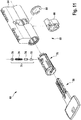
- Fig. 11 shows a locking device 60.
- the locking device has a key 58, as it is, for example Fig. 5 is shown.
- a lock cylinder 62 is also provided.
- the lock cylinder 62 has a housing 64 and a cylinder core 70.
- a snap ring 68 is used to fix the cylinder core 70 in the housing.
- the housing 64 is shown for a double cylinder. In principle, however, a cylinder can be designed on one side.
- the pin tumbler 71 has a core pin 72 and a housing pin 74.
- the pin tumbler 71 can be designed as an active spring-loaded pin tumbler.
- the core pin 72 and the housing pin 74 are pretensioned on the closure element 78 by means of a spring 76.
- the core pin 72 and the housing pin 74 are pressed radially inward and the core pin 72 slides along the key 58.
- the core pin 72 comes into a contact position that is queried. Only when the position is correct is there a parting plane between the core pin 72 and the housing pin 74 on the cutting plane between the cylinder core 70 and the housing 64, which can be rotated out of the cylinder. This position is for example in the sectional view of the Fig. 15 shown.
- the core pin 72 When the key is fully inserted, there is a contact surface of the core pin 72 in the recess 28. For unlocking, the core pin 72 must then be able to enter the recess 28, as will be described below.
- the Fig. 12 shows the further locking fuses that can be provided on the cylinder core 70.
- six pin tumblers 80 can be provided and, furthermore, six vertically arranged profile pins 82 and six horizontally arranged profile pins 84, of which in FIG Fig. 12 only three are shown for reasons of clarity.
- Fig. 13 shows an assembled state with the key 58 fully inserted into the cylinder core.
- the Fig. 14 shows the side view of the locking device with the fully inserted key 58.
- the sectional view XV-XV is shown here, which is created by the seventh pin tumbler and in FIG Fig. 15 is shown.
- the Fig. 15 shows the locking device in an unlocked state with the key 58 fully inserted.
- the key is fully inserted.
- the core pin is shaped such that it enters the recess 28 completely with the bottom surface 32.
- the core pin 72 and the housing pin 74 then lie with their contact surfaces directly on the parting plane 88 between the cylinder core and the housing. It is therefore possible to turn the key and the cylinder core. It can also be seen that if the position was incorrect, the core pin 72 would still protrude into the housing 64. Turning would then be prevented.
- the core pin 72 is as in Figs Figs. 16, 17 shown, complementary to the corresponding profiles and contours of the recess or the bottom surface 32 of the recess 28 of the key 58.
- a support surface 90 accordingly has the same profile as the bottom surface 32.
- the core pin 72 has a lateral recess 92 which is designed to be complementary to the side surface 37 'and a radius there for transitioning to the broad side surface. The core pin 72 can then enter the recess 28 up to the release position.
- a collar surface, denoted by the reference numeral 73 which is designed as a circumferential extension of the radius in the embodiment shown, can serve as a bearing in the core pin in the release position.
- the core pin also has an anti-twist device 96 in order to ensure that the core pin is correctly positioned. Furthermore, the core pin has two run-up bevels 94 in order to be able to slide easily into and out of the recess 28 along corresponding radii of the recess 28.
- Figs. 18a to 18d show this process. If the key is inserted, the core pin 72 slides with its run-up slope on the radius 30 of the surfaces 37 down into the recess. Even when the key is withdrawn, the core pin 72 can thus simply be guided out of the recess again without the user noticing any resistance.
- the Fig. 19 schematically shows a method 100.
- a key blank according to an embodiment of the present invention is provided in step 102.
- a key can then be completed from this in step 104, in particular in which machining is used, in particular wherein the completion comprises the introduction of depressions by means of drilling, such as, for example, the depressions 56 in FIG Fig. 5 .
- step 108 the recesses are machined so that the shaft has a recess through the broad side surfaces.
- a step 110 two rings are then introduced into the cutouts.
- a shaft is non-rotatably arranged in a shaft which extends through the recess into the rings, the two rings being arranged next to one another in the shaft, and an inner diameter of each ring being greater than an outer diameter of the shaft.
- the arrangement of the Fig. 21 who provided a second type key it can further be provided that in a step 106 a step of forming a desired key profile, which takes place by means of machining of the shaft in the longitudinal direction.
- step 106 can also be carried out after step 112 and before step 104,
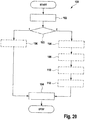
- the Fig. 20 shows a further embodiment of a method according to the invention.
- a step 102 a key blank according to the present invention is provided.
- a step 103 it is then selected whether a key of the first type or of the second type is to be formed. If a key of the first type is to be created, step 106 subsequently takes place as described above and then the step of completing the key 104. The key is then completed. If a key of the second type is to be provided, steps 108 to 112 take place.
- Step 106 can be carried out as in FIG Fig. 20 illustrated by step 108, he but can also be carried out after step 112 and before step 104. In this way, a key of the second type is generated in that the key is then completed in step 104. In this way, by means of the blank 102 according to the invention, it is possible to produce keys of two types from the same blank, which makes production much easier and cheaper.
- the key blank is at a first spatial location or a first manufacturing location 200, as in FIG Fig. 22 shown, is produced. At least the step of finishing 104 can take place at a second manufacturing location 202, which is spatially separate from the first manufacturing location 200.
- the key blank is produced at the first production location 200. This can be a blank that already has a profile 38 formed by means of step 106 or not. Step 106 can also take place later. As a rule, however, it can be provided that step 106 already takes place at the first production location 200.
- the key blank with the formed profile is then transported to the second production location 202. Here, the key is then completed in step 104.
- Steps 108 to 110 and 112 can also be carried out in a first production site 200 in order to provide a key blank with a formed profile and the movable elements, whereas in a second production site 202 only the completion of the key by drilling takes place in order to produce the key for the final Finalize query.
Landscapes
- Lock And Its Accessories (AREA)
- Connection Of Plates (AREA)
Claims (16)
- Ébauche de clé (10) pour la fabrication d'une clé (58) pour un cylindre de fermeture (62), l'ébauche de clé (10) présentant une tige (14) s'étendant le long d'une direction longitudinale (X), la tige (14) présentant une section transversale notamment essentiellement rectangulaire, perpendiculaire à la direction longitudinale (X), la section transversale présentant deux surfaces de côtés larges (18) plus larges et deux surfaces de côtés étroits (16) plus étroites, l'ébauche de clé (10) étant une ébauche de clé réversible, et la tige (14) présentant un évidement (28) avec une surface de fond rectangulaire (32) dans chacune des surfaces de côtés larges (18),
caractérisée en ce qu'une épaisseur de l'ébauche de clé (10) entre les surfaces de fond (32) des évidements (28) est inférieure à 1,8 mm, en ce que sur chacune des surfaces de côtés larges (18) sont disposées au moins une première nervure (24) s'étendant dans la direction longitudinale (X) et une deuxième nervure (26) s'étendant dans la direction longitudinale (X), la première nervure (24), dans une direction parallèle aux surfaces de côtés larges (18) et perpendiculaire à la direction longitudinale (X), étant plus large que la deuxième nervure (26) et en ce que chacun des évidements est disposé entre la première nervure (24) et la deuxième nervure (26) respectives. - Ébauche de clé (10) selon la revendication 1, caractérisée en ce que les surfaces de fond (32) se chevauchent mutuellement dans une direction perpendiculaire aux surfaces de côtés larges (18), en particulier de telle sorte qu'un alésage réalisé perpendiculairement à travers les deux surfaces de côtés larges (18) puisse s'étendre à travers les deux surfaces de base.
- Ébauche de clé (10) selon la revendication 1 ou 2, caractérisée en ce que l'ébauche de clé (10) présente une tête de clé (12) depuis laquelle s'étend la tige (14), et les évidements étant disposés dans un tiers avant de la tige (14) opposé à la tête de clé (12).
- Ébauche de clé (10) selon la revendication 3, caractérisée en ce que la tige (14) présente une pointe de clé (22) opposée à la tête de clé (12), et un centre (45) de chaque évidement (28) étant éloigné de la pointe de clé (22) de 5 mm à 8 mm, notamment de 6 mm à 7 mm.
- Ébauche de clé (10) selon l'une quelconque des revendications 1 à 4, caractérisée en ce qu'une surface latérale de l'évidement (28) s'étendant parallèlement à la direction longitudinale (X) est disposée de manière à se raccorder à la première nervure (24) et l'évidement (28) est ouvert vers la deuxième nervure.
- Ébauche de clé (10) selon l'une quelconque des revendications 1 à 5, caractérisée en ce que la surface de fond rectangulaire (32) présente une longueur parallèle à la direction longitudinale (X) de 1,5 mm à 2,5 mm, en particulier une longueur de 2,12 mm.
- Ébauche de clé (10) selon l'une quelconque des revendications 1 à 6, caractérisée en ce que la surface de fond rectangulaire (32) présente une largeur dans une direction (Y) parallèle aux surfaces de côtés larges (18) et perpendiculaire à la direction longitudinale (X) de 1,5 mm à 2,5 mm, en particulier une largeur de 1,7 mm inclus à 2,1 mm inclus.
- Ébauche de clé (10) selon l'une quelconque des revendications 1 à 7, caractérisée en ce qu'un plan médian (42) s'étendant dans la direction longitudinale (X) de chaque évidement (28) est disposé avec un décalage (44) par rapport à un plan médian (40) de la surface de côté large (18) s'étendant dans la direction longitudinale (X), dans lequel est disposé l'évidement respectif (28).
- Ébauche de clé (10) selon l'une quelconque des revendications 1 à 8, caractérisée en ce que chacun des évidements (28) présente au moins trois, en particulier quatre, surfaces latérales (37, 39), qui s'étendent à chaque fois depuis la surface de côté large respective (18) jusqu'à la surface de fond respective (32), et chacune des surfaces latérales (37, 39) étant inclinée suivant un certain angle (35) par rapport à un plan perpendiculaire aux surfaces de côtés larges (18), et chaque évidement (28) s'ouvrant depuis la surface de fond (32) vers la surface de côté large (18).
- Ébauche de clé (10) selon l'une quelconque des revendications 1 à 9, caractérisée en ce que chacun des évidements (28) présente au moins trois surfaces latérales qui s'étendent à chaque fois depuis la surface de fond respective (32) jusqu'à la surface de côté large respective et au moins une des surfaces latérales se prolonge par un rayon dans la surface de côté large respective.
- Ébauche de clé (10) selon l'une quelconque des revendications 1 à 10, caractérisée en ce qu'une épaisseur maximale entre les surfaces de côtés larges (18) est de 2,4 mm à 2,8 mm, en particulier l'épaisseur maximale entre les surfaces de côtés larges (18) étant de 2,6 mm.
- Clé (58) pour un cylindre de fermeture (62), la clé (58) présentant une tige (14) s'étendant le long d'une direction longitudinale (X), la tige (14) présentant une section transversale notamment essentiellement rectangulaire, perpendiculaire à la direction longitudinale (X), la section transversale présentant deux surfaces de côtés larges (18) plus larges et deux surfaces de côtés étroits (16) plus étroites, la clé (58) étant une clé réversible, et la tige (14) présentant un évidement (28) avec une surface de fond rectangulaire (32) dans chacune des surfaces de côtés larges (18), caractérisée en ce qu'une épaisseur de la clé (58) entre les surfaces de fond (32) des évidements (28) est inférieure à 1,8 mm, et chacun des évidements (28) présente trois surfaces latérales (37, 39) qui s'étendent à chaque fois depuis la surface de côté large respective (18) jusqu'à la surface de fond respective (32), l'une des surfaces latérales s'étendant parallèlement à la direction longitudinale (X) et deux surfaces latérales s'étendant perpendiculairement à la direction longitudinale (X), en ce que sur chacune des surfaces de côtés larges (18) sont disposées au moins une première nervure (24) s'étendant dans la direction longitudinale (X) et une deuxième nervure (26) s'étendant dans la direction longitudinale (X), la première nervure (24), dans une direction parallèle aux surfaces de côtés larges (18) et perpendiculaire à la direction longitudinale (X), étant plus large que la deuxième nervure (26) et en ce que chacun des évidements est disposé entre la première nervure (24) et la deuxième nervure (26) respectives.
- Clé (58) selon la revendication 12, caractérisée en ce qu'une profondeur de chaque évidement (28) depuis la surface de côté large respective jusqu'à la surface de fond respective (32) mesure au maximum 0,8 mm, en particulier au maximum 0,65 mm.
- Dispositif de fermeture comprenant un cylindre de fermeture (62) et une clé (58) selon la revendication 12 ou 13, dans lequel le cylindre de fermeture (62) présente un boîtier (64) et un noyau de cylindre (70), le cylindre de fermeture (62) présentant une pluralité de sécurités, chaque sécurité (71, 80, 82, 84) pouvant être déplacée entre un état de verrouillage et un état de libération et bloquant un mouvement de rotation du noyau de cylindre (70) par rapport au boîtier (64) dans l'état de verrouillage et autorisant ce mouvement dans l'état de libération, et le cylindre de fermeture (62) pouvant être transféré de l'état de verrouillage à l'état de libération par introduction complète de la clé (58) dans le noyau de cylindre (70) et l'une des sécurités (71) étant associée à l'évidement (28).
- Dispositif de fermeture selon la revendication 14, caractérisé en ce que la sécurité (71) associée à l'évidement (28) est réalisée sous forme de gâchette à goupille, en particulier sous forme de gâchette à goupille à ressort active, en particulier la sécurité associée à l'évidement (28) présentant une goupille de boîtier (74) et une goupille de noyau (72), la goupille de noyau (72) présentant une surface d'appui (90) opposée à la goupille de boîtier (74) et la surface d'appui (90) étant disposée dans l'évidement (28) dans l'état de libération.
- Procédé de fabrication d'une clé (58), comprenant les étapes suivantes :• fourniture (102) d'une ébauche de clé (10), l'ébauche de clé (10) présentant une tige (14) s'étendant le long d'une direction longitudinale (X), la tige (14) présentant une section transversale notamment essentiellement rectangulaire, perpendiculaire à la direction longitudinale (X), la section transversale présentant deux surfaces de côtés larges (18) plus larges et deux surfaces de côtés étroits (16) plus étroites, l'ébauche de clé (10) étant une ébauche de clé réversible, et la tige (14) présentant un évidement (28) avec une surface de fond rectangulaire (32) dans chacune des surfaces de côtés larges (18), et une épaisseur de l'ébauche de clé (10) entre les surfaces de fond (32) des évidements (28) étant inférieure à 1,8 mm ;• sélection (103), consistant à établir s'il faut fabriquer une première clé (58) dans laquelle l'évidement (28) sert à interroger une gâchette à goupille, ou une deuxième clé (58) dans laquelle deux bagues sont disposées dans un ajour;• au cas où une première clé (58) doit être fabriquée, mise en œuvre d'au moins les étapes suivantes :∘ fabrication (104) de la clé (58) par usinage par enlèvement de copeaux, la fabrication présentant notamment la réalisation de renfoncements par perçage ;• au cas où une deuxième clé (58) doit être fabriquée, mise en œuvre d'au moins les étapes suivantes :∘ usinage (108), en particulier fraisage, des évidements, de telle sorte que la tige (14) présente un ajour à travers les surfaces de côtés larges (18) ;∘ introduction (110) de deux bagues dans l'ajour ;∘ disposition (112) d'un arbre disposé de manière solidaire en rotation dans la tige (14), lequel s'étend à travers l'ajour et les bagues, les deux bagues étant disposées l'une à côté de l'autre sur l'arbre, et un diamètre intérieur de chaque bague étant supérieur à un diamètre extérieur de l'arbre ; et∘ fabrication (104) de la clé (58) par usinage par enlèvement de copeaux, la fabrication présentant notamment la réalisation de renfoncements par perçage.
Priority Applications (7)
| Application Number | Priority Date | Filing Date | Title |
|---|---|---|---|
| SI201830255T SI3339538T1 (sl) | 2018-03-28 | 2018-03-28 | Ključ surovec za izdelavo ključa za cilinder, ključ, zaporna naprava in postopek |
| DK18164763.7T DK3339538T3 (da) | 2018-03-28 | 2018-03-28 | Blank nøgle til fremstilling af en nøgle til en cylinderlås, nøgle, låseanordning |
| ES18164763T ES2860805T3 (es) | 2018-03-28 | 2018-03-28 | Pieza en bruto de llave para producir una llave para un cierre de cilindro, llave, dispositivo de cierre y método |
| EP18164763.7A EP3339538B1 (fr) | 2018-03-28 | 2018-03-28 | Ébauche de clé pour fabrication d'un clé pour une serrure cylindrique, clé, dispositif de fermeture et procédure |
| HUE18164763A HUE053602T2 (hu) | 2018-03-28 | 2018-03-28 | Nyerskulcs hengerzárhoz való kulcs készítéséhez, kulcs, zárszerkezet és eljárás |
| PL18164763T PL3339538T3 (pl) | 2018-03-28 | 2018-03-28 | Półfabrykat klucza do wytwarzania klucza do wkładki zamkowej |
| HRP20210307TT HRP20210307T1 (hr) | 2018-03-28 | 2021-02-23 | Prazan ključ za proizvodnju ključa za cilindar bravu, ključ, uređaj za zaključavanje i postupak |
Applications Claiming Priority (1)
| Application Number | Priority Date | Filing Date | Title |
|---|---|---|---|
| EP18164763.7A EP3339538B1 (fr) | 2018-03-28 | 2018-03-28 | Ébauche de clé pour fabrication d'un clé pour une serrure cylindrique, clé, dispositif de fermeture et procédure |
Publications (2)
| Publication Number | Publication Date |
|---|---|
| EP3339538A1 EP3339538A1 (fr) | 2018-06-27 |
| EP3339538B1 true EP3339538B1 (fr) | 2021-01-06 |
Family
ID=61837592
Family Applications (1)
| Application Number | Title | Priority Date | Filing Date |
|---|---|---|---|
| EP18164763.7A Active EP3339538B1 (fr) | 2018-03-28 | 2018-03-28 | Ébauche de clé pour fabrication d'un clé pour une serrure cylindrique, clé, dispositif de fermeture et procédure |
Country Status (7)
| Country | Link |
|---|---|
| EP (1) | EP3339538B1 (fr) |
| DK (1) | DK3339538T3 (fr) |
| ES (1) | ES2860805T3 (fr) |
| HR (1) | HRP20210307T1 (fr) |
| HU (1) | HUE053602T2 (fr) |
| PL (1) | PL3339538T3 (fr) |
| SI (1) | SI3339538T1 (fr) |
Families Citing this family (1)
| Publication number | Priority date | Publication date | Assignee | Title |
|---|---|---|---|---|
| AT523792B1 (de) * | 2020-04-20 | 2024-12-15 | Evva Sicherheitstechnologie | Flachschlüssel für ein Zylinderschloss |
Citations (1)
| Publication number | Priority date | Publication date | Assignee | Title |
|---|---|---|---|---|
| DE29818143U1 (de) * | 1998-10-10 | 2000-02-17 | Bks Gmbh, 42549 Velbert | Sicherheitsschlüssel |
Family Cites Families (6)
| Publication number | Priority date | Publication date | Assignee | Title |
|---|---|---|---|---|
| IL153068A (en) * | 2002-11-24 | 2010-12-30 | Dany Markbreit | Backward compatible lock system, key blanks and keys therefor |
| IL177187A0 (en) * | 2006-07-31 | 2006-12-10 | Hamafteach Hamistovev Ltd | Improved locking apparatus |
| IL183168A0 (en) * | 2007-05-14 | 2007-09-20 | Hamafteach Hamistovev Ltd | Improved key blank with moveable elements and improved lock |
| IL191855A0 (en) * | 2008-06-01 | 2009-02-11 | Multi Key Ltd Rav Mafteah Ltd | Key, lock and locking mechanism |
| EP2890856B1 (fr) | 2012-08-29 | 2017-04-12 | dormakaba Schweiz AG | Ébauche, clé de sécurité, système de verrouillage et procédé de fabrication |
| NO2748426T3 (fr) | 2015-07-22 | 2018-03-24 |
-
2018
- 2018-03-28 EP EP18164763.7A patent/EP3339538B1/fr active Active
- 2018-03-28 PL PL18164763T patent/PL3339538T3/pl unknown
- 2018-03-28 HU HUE18164763A patent/HUE053602T2/hu unknown
- 2018-03-28 ES ES18164763T patent/ES2860805T3/es active Active
- 2018-03-28 DK DK18164763.7T patent/DK3339538T3/da active
- 2018-03-28 SI SI201830255T patent/SI3339538T1/sl unknown
-
2021
- 2021-02-23 HR HRP20210307TT patent/HRP20210307T1/hr unknown
Patent Citations (1)
| Publication number | Priority date | Publication date | Assignee | Title |
|---|---|---|---|---|
| DE29818143U1 (de) * | 1998-10-10 | 2000-02-17 | Bks Gmbh, 42549 Velbert | Sicherheitsschlüssel |
Also Published As
| Publication number | Publication date |
|---|---|
| PL3339538T3 (pl) | 2021-06-14 |
| EP3339538A1 (fr) | 2018-06-27 |
| HUE053602T2 (hu) | 2021-07-28 |
| DK3339538T3 (da) | 2021-03-01 |
| SI3339538T1 (sl) | 2021-05-31 |
| HRP20210307T1 (hr) | 2021-04-02 |
| ES2860805T3 (es) | 2021-10-05 |
Similar Documents
| Publication | Publication Date | Title |
|---|---|---|
| DE69815234T2 (de) | Ein programmierbares zylinderschloss mit einem hauptschlüssel | |
| DE69224664T2 (de) | Zylinderschloss-schlüsselkombination | |
| EP3020893B1 (fr) | Système de fermeture et l'utilisation d'une clé dans un tel système | |
| CH710314B1 (de) | Schlüssel und Schloss. | |
| DE2931653C2 (de) | Profilschließzylinder | |
| CH716812B1 (de) | Schlüsselrohling, Schlüssel, Zylinderschloss und Verfahren zur Herstellung eines Schlüsselrohlings und eines Schlüssels. | |
| EP4148212A1 (fr) | Clé, système de fermeture, cylindre de serrure et procédé de fabrication | |
| EP3922788B1 (fr) | Ébauche de clé et clé destinée au fonctionnement d'un cylindre de disque, ainsi que procédé de fabrication d'une telle ébauche de clé et de clé | |
| DE102018107501A1 (de) | Schlüsselrohling zur Herstellung eines Schlüssels für einen Schließzylinder, Schlüssel, Schließvorrichtung und Verfahren | |
| DE102017121226A1 (de) | Schließvorrichtung | |
| EP0607993B1 (fr) | Ensemble de serrures à cylindre, une serrure à cylindre pour former un tel ensemble, dispositif de verrouillage hierarchique à la base d'un tel ensemble, clé pour la serrure à cylindre et méthode de fabrication de la clé | |
| AT516237B1 (de) | Schlüssel sowie zugehöriges Schloss | |
| EP3339538B1 (fr) | Ébauche de clé pour fabrication d'un clé pour une serrure cylindrique, clé, dispositif de fermeture et procédure | |
| CH716813A1 (de) | Schlüssel, Zylinderschloss, Schliesssystem und Verfahren zum Kodieren eines Schlüssels. | |
| EP0633373B1 (fr) | Serrure à cylindre avec clef, ensembles de telles serrures à cylindre, une clef pour une telle serrure et un groupe de clefs et clefs brutes | |
| EP0623719B1 (fr) | Cylindre de fermeture, clé et ensembles d'ébauche de clé pour groupes de cylindres de fermeture | |
| EP3205796B1 (fr) | Clé pour un barillet, barillet et dispositif de fermeture | |
| DE102013103790A1 (de) | Kodierung über Sperrbalken | |
| EP3354826B1 (fr) | Clé améliorée pour un barillet, dispositif de fermeture et procédé | |
| EP4234853B1 (fr) | Cylindre de fermeture programmable | |
| EP3428371B1 (fr) | Barillet de serrure, cylindre de serrure, dispositif de fermeture, serrure à cylindre et procédé correspondant | |
| EP0625624A1 (fr) | Serrure cylindrique | |
| EP0118910A2 (fr) | Cylindre de fermeture | |
| DE4430807A1 (de) | Schließzylinder, Gruppe von Schließzylindern, Schließanlage, Flachschlüssel, Gruppe von Flachschlüsseln, Verfahren zur Herstellung eines Schlüssels und Verfahren zur Herstellung einer Gruppe von Schließzylindern | |
| EP1132553B1 (fr) | Serrure cylindrique |
Legal Events
| Date | Code | Title | Description |
|---|---|---|---|
| PUAI | Public reference made under article 153(3) epc to a published international application that has entered the european phase |
Free format text: ORIGINAL CODE: 0009012 |
|
| STAA | Information on the status of an ep patent application or granted ep patent |
Free format text: STATUS: THE APPLICATION HAS BEEN PUBLISHED |
|
| AK | Designated contracting states |
Kind code of ref document: A1 Designated state(s): AL AT BE BG CH CY CZ DE DK EE ES FI FR GB GR HR HU IE IS IT LI LT LU LV MC MK MT NL NO PL PT RO RS SE SI SK SM TR |
|
| AX | Request for extension of the european patent |
Extension state: BA ME |
|
| STAA | Information on the status of an ep patent application or granted ep patent |
Free format text: STATUS: REQUEST FOR EXAMINATION WAS MADE |
|
| STAA | Information on the status of an ep patent application or granted ep patent |
Free format text: STATUS: EXAMINATION IS IN PROGRESS |
|
| 17P | Request for examination filed |
Effective date: 20181221 |
|
| RBV | Designated contracting states (corrected) |
Designated state(s): AL AT BE BG CH CY CZ DE DK EE ES FI FR GB GR HR HU IE IS IT LI LT LU LV MC MK MT NL NO PL PT RO RS SE SI SK SM TR |
|
| 17Q | First examination report despatched |
Effective date: 20190128 |
|
| GRAP | Despatch of communication of intention to grant a patent |
Free format text: ORIGINAL CODE: EPIDOSNIGR1 |
|
| STAA | Information on the status of an ep patent application or granted ep patent |
Free format text: STATUS: GRANT OF PATENT IS INTENDED |
|
| INTG | Intention to grant announced |
Effective date: 20201030 |
|
| GRAS | Grant fee paid |
Free format text: ORIGINAL CODE: EPIDOSNIGR3 |
|
| GRAA | (expected) grant |
Free format text: ORIGINAL CODE: 0009210 |
|
| STAA | Information on the status of an ep patent application or granted ep patent |
Free format text: STATUS: THE PATENT HAS BEEN GRANTED |
|
| AK | Designated contracting states |
Kind code of ref document: B1 Designated state(s): AL AT BE BG CH CY CZ DE DK EE ES FI FR GB GR HR HU IE IS IT LI LT LU LV MC MK MT NL NO PL PT RO RS SE SI SK SM TR |
|
| REG | Reference to a national code |
Ref country code: GB Ref legal event code: FG4D Free format text: NOT ENGLISH |
|
| REG | Reference to a national code |
Ref country code: AT Ref legal event code: REF Ref document number: 1352540 Country of ref document: AT Kind code of ref document: T Effective date: 20210115 Ref country code: CH Ref legal event code: EP |
|
| REG | Reference to a national code |
Ref country code: DE Ref legal event code: R096 Ref document number: 502018003521 Country of ref document: DE |
|
| REG | Reference to a national code |
Ref country code: IE Ref legal event code: FG4D Free format text: LANGUAGE OF EP DOCUMENT: GERMAN |
|
| REG | Reference to a national code |
Ref country code: HR Ref legal event code: TUEP Ref document number: P20210307 Country of ref document: HR |
|
| REG | Reference to a national code |
Ref country code: DK Ref legal event code: T3 Effective date: 20210224 |
|
| REG | Reference to a national code |
Ref country code: CH Ref legal event code: NV Representative=s name: TROESCH SCHEIDEGGER WERNER AG, CH |
|
| REG | Reference to a national code |
Ref country code: NL Ref legal event code: FP |
|
| REG | Reference to a national code |
Ref country code: HR Ref legal event code: T1PR Ref document number: P20210307 Country of ref document: HR Ref country code: HR Ref legal event code: ODRP Ref document number: P20210307 Country of ref document: HR Payment date: 20210319 Year of fee payment: 4 |
|
| REG | Reference to a national code |
Ref country code: LT Ref legal event code: MG9D |
|
| REG | Reference to a national code |
Ref country code: HU Ref legal event code: AG4A Ref document number: E053602 Country of ref document: HU |
|
| PG25 | Lapsed in a contracting state [announced via postgrant information from national office to epo] |
Ref country code: GR Free format text: LAPSE BECAUSE OF FAILURE TO SUBMIT A TRANSLATION OF THE DESCRIPTION OR TO PAY THE FEE WITHIN THE PRESCRIBED TIME-LIMIT Effective date: 20210407 Ref country code: FI Free format text: LAPSE BECAUSE OF FAILURE TO SUBMIT A TRANSLATION OF THE DESCRIPTION OR TO PAY THE FEE WITHIN THE PRESCRIBED TIME-LIMIT Effective date: 20210106 Ref country code: BG Free format text: LAPSE BECAUSE OF FAILURE TO SUBMIT A TRANSLATION OF THE DESCRIPTION OR TO PAY THE FEE WITHIN THE PRESCRIBED TIME-LIMIT Effective date: 20210406 Ref country code: NO Free format text: LAPSE BECAUSE OF FAILURE TO SUBMIT A TRANSLATION OF THE DESCRIPTION OR TO PAY THE FEE WITHIN THE PRESCRIBED TIME-LIMIT Effective date: 20210406 Ref country code: PT Free format text: LAPSE BECAUSE OF FAILURE TO SUBMIT A TRANSLATION OF THE DESCRIPTION OR TO PAY THE FEE WITHIN THE PRESCRIBED TIME-LIMIT Effective date: 20210506 Ref country code: LT Free format text: LAPSE BECAUSE OF FAILURE TO SUBMIT A TRANSLATION OF THE DESCRIPTION OR TO PAY THE FEE WITHIN THE PRESCRIBED TIME-LIMIT Effective date: 20210106 |
|
| PG25 | Lapsed in a contracting state [announced via postgrant information from national office to epo] |
Ref country code: SE Free format text: LAPSE BECAUSE OF FAILURE TO SUBMIT A TRANSLATION OF THE DESCRIPTION OR TO PAY THE FEE WITHIN THE PRESCRIBED TIME-LIMIT Effective date: 20210106 Ref country code: LV Free format text: LAPSE BECAUSE OF FAILURE TO SUBMIT A TRANSLATION OF THE DESCRIPTION OR TO PAY THE FEE WITHIN THE PRESCRIBED TIME-LIMIT Effective date: 20210106 Ref country code: RS Free format text: LAPSE BECAUSE OF FAILURE TO SUBMIT A TRANSLATION OF THE DESCRIPTION OR TO PAY THE FEE WITHIN THE PRESCRIBED TIME-LIMIT Effective date: 20210106 |
|
| PG25 | Lapsed in a contracting state [announced via postgrant information from national office to epo] |
Ref country code: IS Free format text: LAPSE BECAUSE OF FAILURE TO SUBMIT A TRANSLATION OF THE DESCRIPTION OR TO PAY THE FEE WITHIN THE PRESCRIBED TIME-LIMIT Effective date: 20210506 |
|
| REG | Reference to a national code |
Ref country code: DE Ref legal event code: R097 Ref document number: 502018003521 Country of ref document: DE |
|
| PG25 | Lapsed in a contracting state [announced via postgrant information from national office to epo] |
Ref country code: MC Free format text: LAPSE BECAUSE OF FAILURE TO SUBMIT A TRANSLATION OF THE DESCRIPTION OR TO PAY THE FEE WITHIN THE PRESCRIBED TIME-LIMIT Effective date: 20210106 Ref country code: EE Free format text: LAPSE BECAUSE OF FAILURE TO SUBMIT A TRANSLATION OF THE DESCRIPTION OR TO PAY THE FEE WITHIN THE PRESCRIBED TIME-LIMIT Effective date: 20210106 Ref country code: SM Free format text: LAPSE BECAUSE OF FAILURE TO SUBMIT A TRANSLATION OF THE DESCRIPTION OR TO PAY THE FEE WITHIN THE PRESCRIBED TIME-LIMIT Effective date: 20210106 |
|
| PLBE | No opposition filed within time limit |
Free format text: ORIGINAL CODE: 0009261 |
|
| STAA | Information on the status of an ep patent application or granted ep patent |
Free format text: STATUS: NO OPPOSITION FILED WITHIN TIME LIMIT |
|
| PG25 | Lapsed in a contracting state [announced via postgrant information from national office to epo] |
Ref country code: SK Free format text: LAPSE BECAUSE OF FAILURE TO SUBMIT A TRANSLATION OF THE DESCRIPTION OR TO PAY THE FEE WITHIN THE PRESCRIBED TIME-LIMIT Effective date: 20210106 Ref country code: RO Free format text: LAPSE BECAUSE OF FAILURE TO SUBMIT A TRANSLATION OF THE DESCRIPTION OR TO PAY THE FEE WITHIN THE PRESCRIBED TIME-LIMIT Effective date: 20210106 |
|
| 26N | No opposition filed |
Effective date: 20211007 |
|
| PG25 | Lapsed in a contracting state [announced via postgrant information from national office to epo] |
Ref country code: AL Free format text: LAPSE BECAUSE OF FAILURE TO SUBMIT A TRANSLATION OF THE DESCRIPTION OR TO PAY THE FEE WITHIN THE PRESCRIBED TIME-LIMIT Effective date: 20210106 Ref country code: LU Free format text: LAPSE BECAUSE OF NON-PAYMENT OF DUE FEES Effective date: 20210328 |
|
| REG | Reference to a national code |
Ref country code: HR Ref legal event code: ODRP Ref document number: P20210307 Country of ref document: HR Payment date: 20220317 Year of fee payment: 5 |
|
| PG25 | Lapsed in a contracting state [announced via postgrant information from national office to epo] |
Ref country code: IS Free format text: LAPSE BECAUSE OF FAILURE TO SUBMIT A TRANSLATION OF THE DESCRIPTION OR TO PAY THE FEE WITHIN THE PRESCRIBED TIME-LIMIT Effective date: 20210506 |
|
| REG | Reference to a national code |
Ref country code: HR Ref legal event code: ODRP Ref document number: P20210307 Country of ref document: HR Payment date: 20230317 Year of fee payment: 6 |
|
| P01 | Opt-out of the competence of the unified patent court (upc) registered |
Effective date: 20230512 |
|
| PG25 | Lapsed in a contracting state [announced via postgrant information from national office to epo] |
Ref country code: CY Free format text: LAPSE BECAUSE OF FAILURE TO SUBMIT A TRANSLATION OF THE DESCRIPTION OR TO PAY THE FEE WITHIN THE PRESCRIBED TIME-LIMIT Effective date: 20210106 |
|
| REG | Reference to a national code |
Ref country code: HR Ref legal event code: ODRP Ref document number: P20210307 Country of ref document: HR Payment date: 20240320 Year of fee payment: 7 |
|
| PG25 | Lapsed in a contracting state [announced via postgrant information from national office to epo] |
Ref country code: MK Free format text: LAPSE BECAUSE OF FAILURE TO SUBMIT A TRANSLATION OF THE DESCRIPTION OR TO PAY THE FEE WITHIN THE PRESCRIBED TIME-LIMIT Effective date: 20210106 |
|
| PG25 | Lapsed in a contracting state [announced via postgrant information from national office to epo] |
Ref country code: TR Free format text: LAPSE BECAUSE OF FAILURE TO SUBMIT A TRANSLATION OF THE DESCRIPTION OR TO PAY THE FEE WITHIN THE PRESCRIBED TIME-LIMIT Effective date: 20210106 |
|
| PG25 | Lapsed in a contracting state [announced via postgrant information from national office to epo] |
Ref country code: MT Free format text: LAPSE BECAUSE OF FAILURE TO SUBMIT A TRANSLATION OF THE DESCRIPTION OR TO PAY THE FEE WITHIN THE PRESCRIBED TIME-LIMIT Effective date: 20210106 |
|
| REG | Reference to a national code |
Ref country code: HR Ref legal event code: ODRP Ref document number: P20210307 Country of ref document: HR Payment date: 20250320 Year of fee payment: 8 |
|
| PGFP | Annual fee paid to national office [announced via postgrant information from national office to epo] |
Ref country code: HU Payment date: 20250320 Year of fee payment: 8 |
|
| PGFP | Annual fee paid to national office [announced via postgrant information from national office to epo] |
Ref country code: SI Payment date: 20250319 Year of fee payment: 8 |
|
| PGFP | Annual fee paid to national office [announced via postgrant information from national office to epo] |
Ref country code: ES Payment date: 20250416 Year of fee payment: 8 |
|
| PGFP | Annual fee paid to national office [announced via postgrant information from national office to epo] |
Ref country code: IT Payment date: 20250331 Year of fee payment: 8 |
|
| PGFP | Annual fee paid to national office [announced via postgrant information from national office to epo] |
Ref country code: CH Payment date: 20250401 Year of fee payment: 8 |
|
| REG | Reference to a national code |
Ref country code: CH Ref legal event code: U11 Free format text: ST27 STATUS EVENT CODE: U-0-0-U10-U11 (AS PROVIDED BY THE NATIONAL OFFICE) Effective date: 20260401 |
|
| PGFP | Annual fee paid to national office [announced via postgrant information from national office to epo] |
Ref country code: GB Payment date: 20260324 Year of fee payment: 9 |
|
| PGFP | Annual fee paid to national office [announced via postgrant information from national office to epo] |
Ref country code: DE Payment date: 20260320 Year of fee payment: 9 Ref country code: DK Payment date: 20260323 Year of fee payment: 9 Ref country code: IE Payment date: 20260323 Year of fee payment: 9 |
|
| PGFP | Annual fee paid to national office [announced via postgrant information from national office to epo] |
Ref country code: HR Payment date: 20260320 Year of fee payment: 9 Ref country code: AT Payment date: 20260319 Year of fee payment: 9 |
|
| PGFP | Annual fee paid to national office [announced via postgrant information from national office to epo] |
Ref country code: BE Payment date: 20260323 Year of fee payment: 9 |
|
| PGFP | Annual fee paid to national office [announced via postgrant information from national office to epo] |
Ref country code: NL Payment date: 20260323 Year of fee payment: 9 |
|
| PGFP | Annual fee paid to national office [announced via postgrant information from national office to epo] |
Ref country code: FR Payment date: 20260324 Year of fee payment: 9 |
|
| PGFP | Annual fee paid to national office [announced via postgrant information from national office to epo] |
Ref country code: CZ Payment date: 20260318 Year of fee payment: 9 |
|
| PGFP | Annual fee paid to national office [announced via postgrant information from national office to epo] |
Ref country code: PL Payment date: 20260317 Year of fee payment: 9 |
|
| REG | Reference to a national code |
Ref country code: HR Ref legal event code: ODRP Ref document number: P20210307 Country of ref document: HR Payment date: 20260320 Year of fee payment: 9 |