EP3339934A1 - Kopfmontierte elektronische vorrichtung - Google Patents
Kopfmontierte elektronische vorrichtung Download PDFInfo
- Publication number
- EP3339934A1 EP3339934A1 EP15901487.7A EP15901487A EP3339934A1 EP 3339934 A1 EP3339934 A1 EP 3339934A1 EP 15901487 A EP15901487 A EP 15901487A EP 3339934 A1 EP3339934 A1 EP 3339934A1
- Authority
- EP
- European Patent Office
- Prior art keywords
- axis
- electronic device
- head mounted
- mounted electronic
- coupling
- Prior art date
- Legal status (The legal status is an assumption and is not a legal conclusion. Google has not performed a legal analysis and makes no representation as to the accuracy of the status listed.)
- Withdrawn
Links
Images



Classifications
-
- G—PHYSICS
- G02—OPTICS
- G02B—OPTICAL ELEMENTS, SYSTEMS OR APPARATUS
- G02B27/00—Optical systems or apparatus not provided for by any of the groups G02B1/00 - G02B26/00, G02B30/00
- G02B27/01—Head-up displays
- G02B27/017—Head mounted
- G02B27/0176—Head mounted characterised by mechanical features
-
- H—ELECTRICITY
- H04—ELECTRIC COMMUNICATION TECHNIQUE
- H04R—LOUDSPEAKERS, MICROPHONES, GRAMOPHONE PICK-UPS OR LIKE ACOUSTIC ELECTROMECHANICAL TRANSDUCERS; ELECTRIC HEARING AIDS; PUBLIC ADDRESS SYSTEMS
- H04R1/00—Details of transducers, loudspeakers or microphones
- H04R1/10—Earpieces; Attachments therefor ; Earphones; Monophonic headphones
- H04R1/1058—Manufacture or assembly
- H04R1/1066—Constructional aspects of the interconnection between earpiece and earpiece support
-
- G—PHYSICS
- G02—OPTICS
- G02B—OPTICAL ELEMENTS, SYSTEMS OR APPARATUS
- G02B27/00—Optical systems or apparatus not provided for by any of the groups G02B1/00 - G02B26/00, G02B30/00
- G02B27/01—Head-up displays
- G02B27/0149—Head-up displays characterised by mechanical features
- G02B2027/015—Head-up displays characterised by mechanical features involving arrangement aiming to get less bulky devices
-
- H—ELECTRICITY
- H04—ELECTRIC COMMUNICATION TECHNIQUE
- H04R—LOUDSPEAKERS, MICROPHONES, GRAMOPHONE PICK-UPS OR LIKE ACOUSTIC ELECTROMECHANICAL TRANSDUCERS; ELECTRIC HEARING AIDS; PUBLIC ADDRESS SYSTEMS
- H04R1/00—Details of transducers, loudspeakers or microphones
- H04R1/10—Earpieces; Attachments therefor ; Earphones; Monophonic headphones
- H04R1/1008—Earpieces of the supra-aural or circum-aural type
-
- H—ELECTRICITY
- H04—ELECTRIC COMMUNICATION TECHNIQUE
- H04R—LOUDSPEAKERS, MICROPHONES, GRAMOPHONE PICK-UPS OR LIKE ACOUSTIC ELECTROMECHANICAL TRANSDUCERS; ELECTRIC HEARING AIDS; PUBLIC ADDRESS SYSTEMS
- H04R5/00—Stereophonic arrangements
- H04R5/033—Headphones for stereophonic communication
- H04R5/0335—Earpiece support, e.g. headbands or neckrests
Definitions
- the present disclosure relates to head mounted electronic devices, and more particularly to a head mounted electronic device with a headphone and a display portion which are operable to rotate relative to each other.
- Head mounted electronic device is a near-eye display device. It produces images and projects the images to the eyes of a user, so that the user can see magnified images, and a display effect of large area can be obtained.
- Most of the existing head mounted electronic devices have their audio signals transmitted to the user via earplugs arranged thereon, but the acoustic effect obtained from the earplugs is not satisfactory.
- headphone jacks for the user to plug in headphones with desired acoustic effects.
- this solution makes it difficult to wear, and also inconvenient to carry the headphone and the head mounted electronic device separately.
- embodiments of the present disclosure provide a head mounted electronic device with a headphone and a display portion which are operable to rotate relative to each other.
- a head mounted electronic device includes a headphone and a display portion.
- the headphone includes an elastic belt which is of C-shape and includes two coupling ends, two movable members each rotatably coupled to a corresponding coupling end around a first axis, and two speakers each rotatably coupled to a corresponding movable member around a second axis.
- the display portion includes a main body to produce images and project the images outwardly, and two coupling members coupled to two opposite ends of the main body and each rotatably coupled to a corresponding speaker around a third axis.
- the display portion can enable the speaker to rotate around the first axis and the second axis, so that twisting of the elastic belt and the coupling members can be avoided, and the display portion can be rotated to a position where the display portion and the headphone substantially overlap with each other.
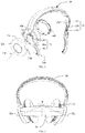
- FIG. 1 is a schematic view of a head mounted electronic device 10 in accordance with a first embodiment of the present disclosure.
- the head mounted electronic device 10 may be a head mounted videoplayer, a head mounted game machine, a head mounted navigator, etc..
- the head mounted electronic device 10 includes a headphone 20 and a display portion 40.
- the display portion 40 is rotatably coupled to the headphone 20.
- the display portion 40 can be rotated to a position where an included angle defined between the display portion 40 and the headphone 20 is substantially 90 degrees, as illustrated by FIG. 1 .
- the display portion 40 is located in front of his/her eyes and projects images to the eyes.
- the display portion 40 can be rotated to a position where the display portion 40 substantially overlap with the headphone 20 to facilitate to store the head mounted electronic device 10, as illustrated by FIG. 5 .
- the headphone 20 includes two speakers 22, an elastic belt 24, and two movable members 26 to rotatably couple the two speakers 22 to the elastic belt 24.
- the elastic belt 24 is substantially C-shaped and includes two coupling ends 25 located at a C-shaped opening.
- the elastic belt 24 can enable the two coupling ends 25 to get close to or away from each other.
- each coupling end 25 includes a receiving part 25a and a first sliding member 25b slidably received in the receiving part 25a.
- a first protrusion post 25c extends from a side of the first sliding member 25b away from the receiving part 25a.
- the first sliding member 25b can be partially slid out of the receiving part 25a.
- the first protrusion post 25c defines a first axis 25d.
- the first sliding member 25b is arranged to allow the user to adjust a distance between the elastic belt 24 and the speaker 22. However, it can be understood that, when the elastic belt 24 is stretchable, or the distance between the elastic belt 24 and speaker 22 does not need to be adjusted, the first sliding member 25b can be omitted.
- Each movable member 26 is rotatably coupled to a corresponding coupling end 25 around the first axis 25d, so that the movable member 26 can be rotated relative to the corresponding coupling end 25 with the first axis 25d as a rotation axis.
- the movable member 26 is substantially curved in shape, and includes a curved main portion 26a, a first hole 26b inwardly concaved from an end of the main portion 26a adjacent to the coupling end 25, and a second protrusion post 26c extending from an opposite end of the main portion 26a and toward the speaker 22.
- the first protrusion post 25c is inserted and locked into the first hole 26b, so that the first protrusion post 25c can be rotated within the first through hole 25a.
- each speaker 22 is rotatably coupled to a corresponding movable member 26 around a second axis 26d, so that the speaker 22 can be rotated relative to the corresponding movable member 26 with the second axis 26d as a rotation axis.
- each speaker 22 includes an inner wall 22a to transmit sound, an outer wall 22b opposite to the inner wall 22a, and a side wall 22c extending from a periphery of the outer wall 22b and toward the inner wall 22a.
- the outer wall 22b and the side wall 22c cooperatively define a cavity (not shown).
- the speaker 22 has a trumpet (not shown) located in the cavity, and a side of the trumpet producing sound faces the inner wall 22a.
- the side wall 22c defines a second through hole 22d.
- the second protrusion post 26c is inserted into the second through hole 22d and locked in the cavity, so that the speaker 22 can be rotated relative to the second protrusion post 26c, that is to say, the second protrusion post 26c defines the second axis 26d.
- the second axis 26d and the first axis 25d define a first included angle ⁇ therebetween.
- the speaker 22 and the movable member 26 can be rotated around the first axis 25d, and the speaker 22 can be further rotated around the second axis 26d, so that the moveable member 26 can be rotated in multiple dimensions.
- the arrangement of the protrusion posts 25c, 26c and the recesses 26b and 22d can be reversed.
- the movable members include the first protrusion posts 25c, and the two first recesses 26b are defined in the coupling ends 25.
- the display portion 40 includes a main body 42 and two coupling members 44.
- the main body 42 is to produce images and project the images outwardly.
- the main body 42 is provided with an image producing device and an optical module (not shown). Images produced by the image producing device are projected in preset directions by the optical module.
- the main body 42 is further provided with an adjusting mechanism (not shown).
- the adjusting mechanism is to adjust a distance between the image producing device and the optical module, to thereby fit near-sighted or far-sighted users.
- the adjusting mechanism can be further to adjust a distance between two combinations of the image producing devices and the optical modules, to thereby fit interpupillary distances of different users.
- the two coupling members 44 are coupled to two opposite ends of the main body 42 and each is also rotatably coupled to a corresponding speaker 22 around a third axis 22e.
- the third axis 22e extends from the outer wall 22b of the speaker 22 and toward the inner wall 22a of the speaker 22.
- the display portion 40 can be rotated to a position where the display portion 40 is apart away from the headphone 20, as illustrated by FIG. 1 , and a position where the display portion 40 and the headphone 20 substantially overlap with each other, as illustrated by FIG. 5 .
- the side wall 22c of the speaker 22 is a cylindrical wall.
- An end of the coupling member 44 adjacent to the speaker 22 is provided with a ring 44a.
- the ring 44a also has a cylindrical wall.
- the ring 44a is coupled to the side wall 22c of the speaker 22 by a clamping member 44b. Thus, the ring 44a can be rotated around a central axis of the side wall 22c. Thus, the side wall 22c of the speaker 22 defines the third axis 22e.
- the third axis 22e is substantially perpendicular to a corresponding first axis 25d and/or a corresponding second axis 26d.
- the display portion 40 can be rotated to the position where the included angle defined between the display portion 40 and the headphone 20 is substantially 90 degrees.
- 90 degrees is just an example, and the degrees may be changed due to different wearing habits of users, for example, the included angle may be 70 degrees, 80 degrees, 100 degrees, or others.
- ends of the two speakers 22 away from the elastic belt 24 are inclined toward each other, as illustrated by FIG. 3 .
- the third axes 22e of the two speakers 22 define a second included angle ⁇ therebetween.
- the arrangement of the incline that is, the second included angle ⁇
- the display portion 40 when it needs to rotate the display portion 40 to the position where the display portion 40 and the headphone 20 substantially overlap with each other, the display portion 40 is rotated in an upward direction as shown in FIG. 3 . Because the third axis 22e is inclined relative to a horizontal direction in FIG. 3 , and the main body 42 cannot be stretched, during the upward rotation of the display portion 40, the right speaker 22 shown in FIG. 1 and FIG. 3 are caused to rotate counterclockwise (shown by an arrow located at the second axis 26d in FIG. 1 ) around the second axis 26d. That is to say, a side of the right speaker 22 adjacent to the first hole 26b is rotated in a direction toward the other speaker 22.
- the other speaker 22 is rotated in an opposite direction. Also, the upward rotation of the display portion 40 further causes the right speaker 22 and the right coupling member 26 shown in FIG. 1 and FIG. 3 to rotate in a direction (shown by an arrow located at the first axis 25d) around the first axis 25d. That is to say, a side of the speaker 22 adjacent to the second protrusion post 26c is rotated in a direction away from the other speaker 22.
- the speaker 22 is more comfortable for ears, to thereby provide better audio effect for users.
- the third axis 22e is not horizontally arranged any more, i.e., the two third axes 22e are not collinear and define an included angle therebetween, the rotation of the display portion 40 relative to the headphone 20 becomes complicated.
- the elastic belt 24 is directly fixed to the speakers 22, that is to say, when the movable members 26 are omitted, the elastic belt 24 and the coupling members 44 are twisted in rotation.
- the rotation of the speaker 22 along two dimensions permits the speaker 22 to rotate around the first axis 25d and the second axis 26d in the rotation when compelled by the movement of the display portion 40, to thereby avoid twisting the elastic belt 24 and the coupling member 44, and make the display portion 40 to rotate to the position where the display portion 40 and the headphone 20 substantially overlap with each other.
- the main portion 26a of the movable member 26 substantially extends about one quarter of a circle, that is to say, the first included angle ⁇ is approximately 90 degrees.
- the first included angle ⁇ is not limited to 90 degrees.
- the first included angle is larger than 30 degrees but less than 150 degrees, or is larger than 210 degrees but less than 330 degrees. At this point, a length of the main portion 26a can be accordingly changed.
- the second included angle ⁇ is substantially 150 degrees when the head mounted electronic device 10 is not subject to any external force. However it can be understood that, for different users, the degrees can be changed, so long as that the headphone 20 is more comfortable for ears.
- the second included angle ⁇ is preferably larger than 100 degrees but less than 170 degrees.
- each of the coupling members 44 can be parallelly coupled to the main body 42 or the speaker 22, so that each coupling member 44 can be moved to a first position adjacent to the main body 42 or the speaker 22 and moved to a second position away from the main body 42 or the speaker 22. Therefore, a distance between the main body 42 and user eyes can be adjusted.
- the display portion 40 further includes supporting members 46 extending outwardly from two opposite ends of the main body 42, and the coupling member 44 can be slidably coupled to the supporting member 46, so that the main body 42 can be moved to be close to or away from the speakers 22.
- a manner in which the coupling member 44 is parallelly and movably coupled to the speaker 22 is similar to the structure connection principle of the aforesaid way, and will not be repeated herein.
- first means two or more than two, unless there is a specific limitation.
- the terms “mount”, “connected” and “connection” should be broadly understood, for example, it may be a fixed connection, or may be a detachable connection, or an integral connection; it may be directly connected, or may be indirectly connected via intermediary, or may be communication between interiors of two elements or interactions between two elements.
- the terms “mount”, “connected” and “connection” should be broadly understood, for example, it may be a fixed connection, or may be a detachable connection, or an integral connection; it may be directly connected, or may be indirectly connected via intermediary, or may be communication between interiors of two elements or interactions between two elements.
Landscapes
- Physics & Mathematics (AREA)
- Engineering & Computer Science (AREA)
- Acoustics & Sound (AREA)
- Signal Processing (AREA)
- General Physics & Mathematics (AREA)
- Optics & Photonics (AREA)
- Manufacturing & Machinery (AREA)
- Headphones And Earphones (AREA)
- Details Of Audible-Bandwidth Transducers (AREA)
- Health & Medical Sciences (AREA)
- Otolaryngology (AREA)
Applications Claiming Priority (1)
| Application Number | Priority Date | Filing Date | Title |
|---|---|---|---|
| PCT/CN2015/087566 WO2017028283A1 (zh) | 2015-08-19 | 2015-08-19 | 头戴式电子装置 |
Publications (2)
| Publication Number | Publication Date |
|---|---|
| EP3339934A1 true EP3339934A1 (de) | 2018-06-27 |
| EP3339934A4 EP3339934A4 (de) | 2019-04-10 |
Family
ID=58051541
Family Applications (1)
| Application Number | Title | Priority Date | Filing Date |
|---|---|---|---|
| EP15901487.7A Withdrawn EP3339934A4 (de) | 2015-08-19 | 2015-08-19 | Kopfmontierte elektronische vorrichtung |
Country Status (6)
| Country | Link |
|---|---|
| US (1) | US10095037B2 (de) |
| EP (1) | EP3339934A4 (de) |
| JP (1) | JP6591659B2 (de) |
| KR (1) | KR102003629B1 (de) |
| CN (1) | CN107003515B (de) |
| WO (1) | WO2017028283A1 (de) |
Families Citing this family (10)
| Publication number | Priority date | Publication date | Assignee | Title |
|---|---|---|---|---|
| WO2017113319A1 (zh) * | 2015-12-31 | 2017-07-06 | 深圳市柔宇科技有限公司 | 柔性穿戴设备 |
| CN107407809B (zh) * | 2016-01-26 | 2020-04-14 | 深圳市柔宇科技有限公司 | 头戴式设备、耳机装置及头戴式设备分离控制方法 |
| US10194225B2 (en) * | 2017-03-05 | 2019-01-29 | Facebook Technologies, Llc | Strap arm of head-mounted display with integrated audio port |
| WO2019090459A1 (zh) * | 2017-11-07 | 2019-05-16 | 深圳市柔宇科技有限公司 | 头戴显示设备 |
| JP1656733S (de) * | 2019-11-01 | 2020-04-06 | ||
| US11729553B2 (en) * | 2020-05-29 | 2023-08-15 | Sony Interactive Entertainment Inc. | Headset mechanism for comfort coupling ear cups to head |
| USD968366S1 (en) * | 2020-07-17 | 2022-11-01 | Ming Liu | Headphones |
| US11327322B1 (en) * | 2021-03-19 | 2022-05-10 | Htc Corporation | Head mounted display device |
| CN113141558B (zh) * | 2021-04-13 | 2022-04-22 | 吴曼莉 | 一种适用于英语听力训练的耳机 |
| CN116546356B (zh) * | 2022-01-26 | 2026-04-07 | 北京字跳网络技术有限公司 | 头戴设备的绑带组件、头戴设备 |
Family Cites Families (74)
| Publication number | Priority date | Publication date | Assignee | Title |
|---|---|---|---|---|
| US5003300A (en) | 1987-07-27 | 1991-03-26 | Reflection Technology, Inc. | Head mounted display for miniature video display system |
| US5293647A (en) * | 1991-08-19 | 1994-03-15 | Michael Mirmilshteyn | Multi-adjustable headset |
| US5321416A (en) | 1992-07-27 | 1994-06-14 | Virtual Research Systems | Head-mounted visual display apparatus |
| US6448944B2 (en) | 1993-10-22 | 2002-09-10 | Kopin Corporation | Head-mounted matrix display |
| US6424321B1 (en) | 1993-10-22 | 2002-07-23 | Kopin Corporation | Head-mounted matrix display |
| US7310072B2 (en) | 1993-10-22 | 2007-12-18 | Kopin Corporation | Portable communication display device |
| US5903395A (en) | 1994-08-31 | 1999-05-11 | I-O Display Systems Llc | Personal visual display system |
| US5737012A (en) | 1994-12-01 | 1998-04-07 | Olympus Optical Co., Ltd. | Head mounted image display apparatus and image forming apparatus related thereto |
| US6369952B1 (en) | 1995-07-14 | 2002-04-09 | I-O Display Systems Llc | Head-mounted personal visual display apparatus with image generator and holder |
| US7210160B2 (en) | 1999-05-28 | 2007-04-24 | Immersion Entertainment, L.L.C. | Audio/video programming and charging system and method |
| KR20020061776A (ko) * | 2001-01-17 | 2002-07-25 | (주)서원케이텍크 | 헤드셋 장치 |
| US20040201695A1 (en) | 2001-02-15 | 2004-10-14 | Rei Inasaka | System for delivering news |
| CN2525546Y (zh) | 2001-09-12 | 2002-12-11 | 深圳市东方景电子有限公司 | 头戴式显示器及配套使用的便携式影音装置 |
| AT414198B (de) * | 2003-01-31 | 2006-10-15 | Akg Acoustics Gmbh | Kopfhörer |
| JP2006086980A (ja) * | 2004-09-17 | 2006-03-30 | Audio Technica Corp | ヘッドホン装置 |
| JP4965800B2 (ja) | 2004-10-01 | 2012-07-04 | キヤノン株式会社 | 画像表示システム |
| CN2819243Y (zh) | 2005-08-19 | 2006-09-20 | 宝陆科技股份有限公司 | 头戴式显示器调整结构 |
| JP2007243631A (ja) * | 2006-03-09 | 2007-09-20 | Nikon Corp | ヘッドマウントディスプレイ装置 |
| JP5055585B2 (ja) | 2006-03-15 | 2012-10-24 | 株式会社ニコン | ヘッドマウントディスプレイ |
| JP5163492B2 (ja) | 2006-06-27 | 2013-03-13 | 株式会社ニコン | 映像表示装置 |
| CN2938154Y (zh) | 2006-08-17 | 2007-08-22 | 欧以良 | 头佩式眼镜显示器 |
| CN101336008B (zh) * | 2007-08-24 | 2011-12-07 | 中名(东莞)电子有限公司 | 一种旋转折叠式耳机 |
| JP2009177574A (ja) * | 2008-01-25 | 2009-08-06 | Sony Corp | ヘッドホン |
| JP4674634B2 (ja) * | 2008-12-19 | 2011-04-20 | ソニー株式会社 | 頭部装着型ディスプレイ |
| CN201336696Y (zh) * | 2008-12-22 | 2009-10-28 | 深圳市亿思达显示科技有限公司 | 一种具有存储播放功能的数字眼镜电视 |
| KR200461682Y1 (ko) * | 2010-03-03 | 2012-07-30 | 주식회사 이노디자인 | 입체영상용 판독장치가 구비된 헤드셋 |
| WO2011137034A1 (en) * | 2010-04-27 | 2011-11-03 | Kopin Corporation | Wearable electronic display |
| US8446676B2 (en) | 2010-09-16 | 2013-05-21 | Olympus Corporation | Head-mounted display device |
| US20120098971A1 (en) | 2010-10-22 | 2012-04-26 | Flir Systems, Inc. | Infrared binocular system with dual diopter adjustment |
| JP2012138654A (ja) | 2010-12-24 | 2012-07-19 | Sony Corp | ヘッド・マウント・ディスプレイ |
| CN202026447U (zh) | 2011-03-24 | 2011-11-02 | 旭丽电子(广州)有限公司 | 蓝牙耳机 |
| US20130195308A1 (en) * | 2011-08-02 | 2013-08-01 | 180S, Inc. | Ear warmer |
| CN102387442B (zh) * | 2011-09-22 | 2014-11-05 | 深圳市冠旭电子有限公司 | 一种头戴耳机 |
| JP5942467B2 (ja) | 2012-02-22 | 2016-06-29 | ソニー株式会社 | 表示装置 |
| US8577427B2 (en) | 2012-03-08 | 2013-11-05 | Lee Serota | Headset with adjustable display and integrated computing system |
| CN202455514U (zh) | 2012-03-09 | 2012-09-26 | 王承延 | 一种耳机的耳机体活动装置 |
| JP2012191624A (ja) * | 2012-03-21 | 2012-10-04 | Nikon Corp | ヘッドマウントディスプレイ装置 |
| CN103581779A (zh) | 2012-07-31 | 2014-02-12 | 扬州田治科技有限公司 | 一种旋转耳机 |
| US9143673B2 (en) | 2012-09-19 | 2015-09-22 | Google Inc. | Imaging device with a plurality of pixel arrays |
| TW201419883A (zh) * | 2012-11-12 | 2014-05-16 | Powertech Ind Co Ltd | 頭戴式耳機裝置 |
| US20160004082A1 (en) | 2013-02-12 | 2016-01-07 | Virtual Goggles Inc. | Headset with Binary Display and Integrated Computing System |
| CN103149690B (zh) | 2013-03-01 | 2016-03-02 | 南京理工大学 | 一种3d头戴显示器 |
| KR20160005680A (ko) | 2013-03-15 | 2016-01-15 | 임미 인크. | 비동공 형성 광 경로를 갖는 헤드마운트 디스플레이 |
| JP2014178960A (ja) | 2013-03-15 | 2014-09-25 | Sony Corp | 加速度感覚呈示装置、加速度感覚呈示方法および加速度感覚呈示システム |
| US10137361B2 (en) | 2013-06-07 | 2018-11-27 | Sony Interactive Entertainment America Llc | Systems and methods for using reduced hops to generate an augmented virtual reality scene within a head mounted system |
| US10905943B2 (en) | 2013-06-07 | 2021-02-02 | Sony Interactive Entertainment LLC | Systems and methods for reducing hops associated with a head mounted system |
| CN104254025A (zh) * | 2013-06-27 | 2014-12-31 | 麦祖怀 | 智能耳机 |
| KR20150043122A (ko) | 2013-10-14 | 2015-04-22 | 에스케이하이닉스 주식회사 | 반도체 장치 |
| CN103596099A (zh) | 2013-12-03 | 2014-02-19 | 全南三扬电子有限公司 | 一种旋转耳机 |
| CN103702257B (zh) * | 2013-12-27 | 2017-04-19 | 青岛歌尔声学科技有限公司 | 一种多角度调节的头戴式耳机 |
| CN203747962U (zh) | 2014-03-04 | 2014-07-30 | 杭州鐵三角科技有限公司 | 一种耳机用可变角度的转动装置 |
| JP2016014730A (ja) | 2014-07-01 | 2016-01-28 | セイコーエプソン株式会社 | 画像表示装置 |
| US10034508B2 (en) | 2014-08-12 | 2018-07-31 | Microsoft Technology Licensing, Llc | Weight-distributing headband for head-worn assembly |
| CN104166239A (zh) | 2014-08-25 | 2014-11-26 | 成都贝思达光电科技有限公司 | 一种用于高清摄像机的头戴式视频眼镜取景装置 |
| CN104254037B (zh) | 2014-09-30 | 2017-08-11 | 广东欧珀移动通信有限公司 | 耳壳转轴机构及其头戴式耳机 |
| CN204180248U (zh) | 2014-11-13 | 2015-02-25 | 许辅松 | 头戴式耳机的联接结构 |
| CN204229050U (zh) * | 2014-12-03 | 2015-03-25 | 成都贝思达光电科技有限公司 | 一种便携式可翻转视频眼镜 |
| CN104503086A (zh) * | 2014-12-31 | 2015-04-08 | 青岛歌尔声学科技有限公司 | 可调节式头戴显示器 |
| CN104503585A (zh) | 2014-12-31 | 2015-04-08 | 青岛歌尔声学科技有限公司 | 触控式头戴显示器 |
| CN104503584A (zh) | 2014-12-31 | 2015-04-08 | 青岛歌尔声学科技有限公司 | 一种触控式头戴显示器 |
| CN104635340B (zh) | 2014-12-31 | 2017-04-12 | 青岛歌尔声学科技有限公司 | 一种佩戴式显示器 |
| CN204302573U (zh) | 2014-12-31 | 2015-04-29 | 青岛歌尔声学科技有限公司 | 一种头戴显示器 |
| CN104503083B (zh) * | 2014-12-31 | 2017-01-11 | 青岛歌尔声学科技有限公司 | 一种可调节式头戴显示器 |
| US9635450B2 (en) | 2015-02-20 | 2017-04-25 | Oculus Vr, Llc | Audio headphones for virtual reality head-mounted display |
| CN204575970U (zh) | 2015-03-18 | 2015-08-19 | 青岛歌尔声学科技有限公司 | 一种头戴显示器 |
| CN104765149B (zh) | 2015-03-18 | 2018-09-04 | 青岛歌尔声学科技有限公司 | 一种头戴显示器 |
| CN204666953U (zh) | 2015-04-01 | 2015-09-23 | 深圳市柔宇科技有限公司 | 一种头戴式显示设备 |
| WO2016191960A1 (zh) | 2015-05-29 | 2016-12-08 | 深圳市柔宇科技有限公司 | 显示模组及具有该显示模组的电子装置 |
| US9832561B2 (en) | 2015-06-11 | 2017-11-28 | Oculus Vr, Llc | Detachable audio system for head-mounted displays |
| KR101962563B1 (ko) | 2015-08-19 | 2019-03-26 | 선전 로욜 테크놀로지스 컴퍼니 리미티드 | 헤드마운트형 전자 기기 |
| WO2017028281A1 (zh) | 2015-08-19 | 2017-02-23 | 深圳市柔宇科技有限公司 | 头戴式电子装置 |
| WO2017028282A1 (zh) | 2015-08-19 | 2017-02-23 | 深圳市柔宇科技有限公司 | 穿戴式显示设备 |
| WO2017045110A1 (zh) | 2015-09-14 | 2017-03-23 | 深圳市柔宇科技有限公司 | 一种头戴式显示设备 |
| JP2018530230A (ja) | 2015-09-27 | 2018-10-11 | シェンジェン ロイオル テクノロジーズ カンパニー リミテッドShenzhen Royole Technologies Co., Ltd. | ヘッドマウントディスプレイデバイス |
-
2015
- 2015-08-19 JP JP2018507545A patent/JP6591659B2/ja not_active Expired - Fee Related
- 2015-08-19 CN CN201580001425.7A patent/CN107003515B/zh not_active Expired - Fee Related
- 2015-08-19 KR KR1020177031795A patent/KR102003629B1/ko not_active Expired - Fee Related
- 2015-08-19 EP EP15901487.7A patent/EP3339934A4/de not_active Withdrawn
- 2015-08-19 WO PCT/CN2015/087566 patent/WO2017028283A1/zh not_active Ceased
-
2016
- 2016-03-01 US US15/057,877 patent/US10095037B2/en not_active Expired - Fee Related
Also Published As
| Publication number | Publication date |
|---|---|
| CN107003515B (zh) | 2020-04-14 |
| US10095037B2 (en) | 2018-10-09 |
| WO2017028283A1 (zh) | 2017-02-23 |
| CN107003515A (zh) | 2017-08-01 |
| EP3339934A4 (de) | 2019-04-10 |
| JP6591659B2 (ja) | 2019-10-16 |
| KR102003629B1 (ko) | 2019-07-24 |
| US20170055057A1 (en) | 2017-02-23 |
| KR20170134607A (ko) | 2017-12-06 |
| JP2018526907A (ja) | 2018-09-13 |
Similar Documents
| Publication | Publication Date | Title |
|---|---|---|
| EP3339934A1 (de) | Kopfmontierte elektronische vorrichtung | |
| US9900695B2 (en) | Head-mounted electronic device | |
| US10042168B2 (en) | Head-mounted electronic device | |
| JP6248227B1 (ja) | マイクロディスプレイベースの没入型ヘッドセット | |
| CN105182533B (zh) | 头戴显示器 | |
| CN106461940B (zh) | 穿戴式电子装置 | |
| CN204945492U (zh) | 头戴显示器 | |
| EP3351995A1 (de) | Kopfmontierte anzeigevorrichtung | |
| JP2018067929A5 (de) | ||
| JP6797912B2 (ja) | ウェアラブル装置 | |
| US20050168824A1 (en) | Binocular virtual display imaging device | |
| CN207181820U (zh) | 虚拟现实头戴式显示设备 | |
| KR20140013676A (ko) | 디스플레이 단말기 헤드마운트 장치 | |
| WO2022062020A1 (zh) | 一种头戴设备 | |
| CN111929904A (zh) | 一种头戴设备 | |
| CN115804083A (zh) | 显示装置 | |
| CN107850776A (zh) | 穿戴式电子装置 | |
| US20190364355A1 (en) | Head-mounted display device | |
| BRPI0608925A2 (pt) | dispositivo eletroacústico | |
| TWI663429B (zh) | 頭戴顯示器 | |
| CN209462550U (zh) | 头戴式耳机 | |
| CN106031194A (zh) | 穿戴式电子装置 |
Legal Events
| Date | Code | Title | Description |
|---|---|---|---|
| PUAI | Public reference made under article 153(3) epc to a published international application that has entered the european phase |
Free format text: ORIGINAL CODE: 0009012 |
|
| 17P | Request for examination filed |
Effective date: 20171106 |
|
| AK | Designated contracting states |
Kind code of ref document: A1 Designated state(s): AL AT BE BG CH CY CZ DE DK EE ES FI FR GB GR HR HU IE IS IT LI LT LU LV MC MK MT NL NO PL PT RO RS SE SI SK SM TR |
|
| AX | Request for extension of the european patent |
Extension state: BA ME |
|
| DAV | Request for validation of the european patent (deleted) | ||
| DAX | Request for extension of the european patent (deleted) | ||
| A4 | Supplementary search report drawn up and despatched |
Effective date: 20190311 |
|
| RIC1 | Information provided on ipc code assigned before grant |
Ipc: H04R 1/10 20060101AFI20190305BHEP Ipc: H04R 5/033 20060101ALN20190305BHEP Ipc: G02B 27/01 20060101ALI20190305BHEP |
|
| 17Q | First examination report despatched |
Effective date: 20191120 |
|
| STAA | Information on the status of an ep patent application or granted ep patent |
Free format text: STATUS: THE APPLICATION HAS BEEN WITHDRAWN |
|
| 18W | Application withdrawn |
Effective date: 20200117 |