EP3340199A1 - Dispositif émetteur-récepteur, module de notification, module électronique portable, procédé de désactivation sans contact d'un état d'alarme d'un module de notification et programme informatique - Google Patents
Dispositif émetteur-récepteur, module de notification, module électronique portable, procédé de désactivation sans contact d'un état d'alarme d'un module de notification et programme informatique Download PDFInfo
- Publication number
- EP3340199A1 EP3340199A1 EP17207362.9A EP17207362A EP3340199A1 EP 3340199 A1 EP3340199 A1 EP 3340199A1 EP 17207362 A EP17207362 A EP 17207362A EP 3340199 A1 EP3340199 A1 EP 3340199A1
- Authority
- EP
- European Patent Office
- Prior art keywords
- module
- unit
- light
- data
- portable electronic
- Prior art date
- Legal status (The legal status is an assumption and is not a legal conclusion. Google has not performed a legal analysis and makes no representation as to the accuracy of the status listed.)
- Granted
Links
Images

Classifications
-
- G—PHYSICS
- G08—SIGNALLING
- G08B—SIGNALLING SYSTEMS, e.g. PERSONAL CALLING SYSTEMS; ORDER TELEGRAPHS; ALARM SYSTEMS
- G08B29/00—Checking or monitoring of signalling or alarm systems; Prevention or correction of operating errors, e.g. preventing unauthorised operation
- G08B29/02—Monitoring continuously signalling or alarm systems
- G08B29/04—Monitoring of the detection circuits
- G08B29/043—Monitoring of the detection circuits of fire detection circuits
-
- G—PHYSICS
- G08—SIGNALLING
- G08B—SIGNALLING SYSTEMS, e.g. PERSONAL CALLING SYSTEMS; ORDER TELEGRAPHS; ALARM SYSTEMS
- G08B17/00—Fire alarms; Alarms responsive to explosion
-
- G—PHYSICS
- G08—SIGNALLING
- G08B—SIGNALLING SYSTEMS, e.g. PERSONAL CALLING SYSTEMS; ORDER TELEGRAPHS; ALARM SYSTEMS
- G08B25/00—Alarm systems in which the location of the alarm condition is signalled to a central station, e.g. fire or police telegraphic systems
- G08B25/001—Alarm cancelling procedures or alarm forwarding decisions, e.g. based on absence of alarm confirmation
Definitions
- a triggered alarm may be reset directly at the detector if at least one line of sight to the detector is present.
- the reset is usually done by means of a push button, the push button is installed directly on the detector. Since the detectors are often mounted on ceilings of a room, it is difficult for a person to reach the push button readily and / or without further aids.
- the publication DE 10 2012 201 589 A1 which is probably the closest prior art, describes a fire detector with a fire sensor device for detecting a fire and for outputting a fire signal, with an environmental sensor device for detecting bodies in the vicinity of the fire detector and for outputting an environmental signal, with a control device which in Dependence of the fire signal sets a normal state and an alarm state of the fire alarm, wherein the fire detector is designed as a man-machine interface and the controller checks whether the ambient signal is to be regarded as a user input.
- a transmitter-receiver device with the features of claim 1 is proposed.
- a reporting module with the features of claim 5
- a portable electronic module with the features of claim 8
- a method for contactless deactivation of an alarm condition of a reporting module with the features of claim 13 and a computer program with the features of claim 14 is proposed.
- a transmitter-receiver device comprises at least one portable electronic module as a transmitter and at least one reporting module as a receiver.
- the reporting module is in particular a stationary reporting module and, for example, a peripheral device.
- the signaling module is preferably designed for alarm output, in particular output of an audible and / or visual alarm.
- the electronic module is in particular a handheld device for a person and / or a user.
- the reporting module is designed as a receiver to interact with a plurality of transmitters, in particular portable electronic modules, and / or coupled.
- the portable electronic module is preferably designed to interact with a plurality of reporting modules and / or coupled.
- the reporting module can be arranged in a monitoring area.
- the monitoring area is, for example, a building, in particular a house, a factory and / or an airport.
- the signaling module can be arranged and / or arranged, for example, on the wall and / or on the ceiling of the monitoring area.
- the signaling module is preferably designed to monitor the monitoring area in terms of safety.
- the signaling module comprises a detection device and a control device.
- the control device and the detection device form a common central computer device.
- Detection device and control device are in particular connected to each other in terms of data technology.
- the detection device is designed to receive an event in the monitoring area detect.
- the detection device comprises a sensor for detecting the event and a detection evaluation device for determining and detecting the event based on the sensor data.
- the event is, for example, a fire, a movement, a flooding, a temperature rise and / or a break-in in the surveillance area.
- the detection device is designed to provide the detected event of the control device in terms of data as event data.
- the event data is digital data, alternatively the event data is analog data.
- the event data includes information on the type of event, the time of the event, an intensity of the event, and / or a level of the detected event.
- the control device is designed to set the reporting module in an alarm state and in a normal state based on the event data. As long as no event in the monitoring area is detected by the detection device, it is assumed that no event is present in the monitoring area and thus the reporting module is in the normal state and / or set. If an event in the monitoring area is detected by the detection device, the reporting module is set to the alarm state. In response to the setting of the reporting module to the alarm state, for example, an audible alarm signal is output and / or an alarm message, for example via a network, in particular a security network, directed to a monitoring center, which can then take further action.
- a network in particular a security network
- the portable electronic module comprises an encoding unit and a light-emitting unit.
- the coding unit is preferably a microchip, a computer unit or a data technology application.
- the coding unit is designed to code acknowledgment data and to provide the light-emitting unit.
- the coding unit is designed to code acknowledgment data according to a predetermined and / or adjustable protocol and / or coding key.
- the coded acknowledgment data are in particular digital data.
- the acknowledgment data is from User provided and / or include a command for the control device for switching the reporting module from the alarm state to the normal state.
- the light-emitting unit is configured to emit light.
- the light-emitting unit is a directed light source, for example with a predetermined emission direction.
- the light-emitting unit is a point source and / or a flat light source.
- the light-emitting unit is configured to output the coded acknowledgment data as a coded light signal.
- the coded light signal is a change of emission and not emission of light, in particular on / off the light source.
- the coded light signal is preferably understood to be the temporal variation of the light signal in terms of the intensity and / or the color of the light signal.
- the coded light signal may be a specific shape and / or a specific coded pattern.
- the reporting module comprises a light receiving unit and a decoding unit.
- the decoding unit includes the light receiving unit.
- the light receiving unit is for example a photodiode and is designed to detect light and output it as a signal.
- the light receiving unit is configured to receive the coded light signal of the portable electronic module.
- the light receiving unit is preferably designed to convert the received coded light signal into an electrical signal, in particular to convert it into a digital or analog signal and to provide the detection device with data technology.
- the decoding unit is, for example, a computer device, a computer chip or a computer unit.
- the decoding unit is designed to decode the encoded light signal provided by the light receiving unit and to provide it as acknowledgment data to the control device.
- the same coding key and / or the same protocol is used for decoding the light signal as for coding the acknowledgment data by the coding unit.
- the decoded acknowledgment data corresponds to the unacknowledged acknowledgment data encoded by the coding unit.
- the control module is designed to set the signaling module from the alarm state to the normal state based on the acknowledgment data.
- the control module is designed to set the signaling module from the alarm state to the normal state only for a specific acknowledgment data record, wherein the acknowledgment data record is part of the acknowledgment data and comprises an instruction and / or a command for setting the normal state of the reporting module.
- the control module is configured to set the notification module from the alarm state to the normal state if the acknowledgment data includes the information that no event is present in the monitoring area and / or that the event is a false alarm.
- the invention has the advantage that a transmitter-receiver device is provided which enable the non-contact acknowledgment of the alarm and / or the non-contact reset of a reporting module in a monitoring area.
- the acknowledgment is safe against a false acknowledgment of the alarm, since by the use of portable electronic modules, for example, only a certain group of people can acknowledge the alarm.
- the coded light signal is a light signal in the visible wavelength range and / or in the infrared range.
- the light signal is a light signal of a thermal light source, alternatively and / or additionally, the light signal is a light signal of a non-thermal light source.
- the light signal is a white light light signal, alternatively, the light signal is a color light signal, such as a blue or red light signal.
- the coded light signal comprises an infrared component.
- the coded light signal is preferably a light signal which has been coded and / or encrypted based on the RC5, the RC6, the RECS80, the NEC or the RCMM code.
- This embodiment is based on the idea to use a light signal and / or a light source for the transceiver device, the specially adapted to the field of application of the receiver, in particular of the reporting module, adapted, for example, that a smoke detector uses a light signal in the infrared range.
- radio interface and radio interference interface are designed as WLAN interface, Bluetooth interface, IR interface or other radio interface.
- the radio interface and the radio interference interface can be coupled to one another in terms of data technology, wherein auxiliary data can be exchanged by means of the data-related coupling of the radio interface with the radio interference interface.
- the auxiliary data can be exchanged from the radio interface in the direction of the radio interference interface and / or from the radio interference interface in the direction of the radio interface.
- the auxiliary data includes information for verifying a changeover of the reporting module from the alarm state to the normal state.
- the auxiliary data include the ID of the user and / or the ID of the electronic module, wherein, for example, the control module is configured to switch the alarm module from the alarm state to the normal state only if the ID of the user and / or the ID of the electronic module is deposited and / or is entitled to do so.
- the auxiliary data include the ID of the detector, wherein, for example, the ID of the detector is required to generate the key and / or the protocol.
- the auxiliary data it is possible in particular for the auxiliary data to comprise information that the coded light signal is transmitted and / or the light source is active, so that, for example, the control module is designed to activate the light receiving unit for receiving the coded light signal. This embodiment is based on the consideration to provide a transceiver device which reduces the false detection rate of a shutdown and / or acknowledgment of an alarm.
- the auxiliary data comprise coding and / or decoding information.
- the auxiliary data comprises the key, the coding key and / or the coding protocol and / or decoding the light signal.
- the auxiliary data are designed to transfer the protocol and / or the key from the reporting module to the portable electronic module and / or vice versa.
- the key and / or the protocol is a dynamic key and / or a dynamic protocol. This refinement is based on the consideration of providing a particularly attack-proof coding and / or decoding method of the transceiver device.
- the reporting module is designed and / or provided in particular for the transceiver device.
- the signaling module can be arranged in a surveillance area, for example a house, in particular on a wall and / or a ceiling of the surveillance area.
- the signaling module comprises a detection device and a control device.
- the detection device is designed to detect an event, for example a fire and / or a break-in, in the monitoring area and to provide the control device with the detected event as event data.
- the reporting module comprises a light receiving unit and a decoding unit.
- the light receiving unit is part of the decoding unit.
- the light receiving unit is a photosensitive device such as a photodiode.
- the light receiving unit is configured to receive a coded light signal and to provide the detection device with data technology.
- the detection device is provided with the coded light signal as an analog electrical signal and / or as a digital electrical signal.
- the decoding unit is designed to decode the light signal and to provide it as acknowledgment data to the control device.
- the control module is designed to set the signaling module from the alarm state to the normal state based on the acknowledgment data.
- the control module is configured to set the notification module from the alarm state to the normal state, in the event that the acknowledgment data includes information that the detected event is a false alarm and / or information that the alarm state should be set to the active state.
- This invention is based on the consideration to provide a reporting module which can be set by means of a transmitter device contactlessly from an alarm state to a normal state, so that a false alarm can be acknowledged.
- the light receiving unit comprises a daylight filter and / or an infrared filter, wherein the coded light signal comprises an infrared signal and / or a light signal component in the visible wavelength range of the light.
- Light in the infrared range is preferably light with a wavelength between 800 nanometers and 1 millimeter.
- the daylight filter is in particular designed to filter out light in the wavelength range outside the visible light range and to allow only light in the visible wavelength range to pass.
- the infrared filter is designed to allow light to pass preferably in the infrared range and to filter out light in the visible wavelength range. This embodiment is based on the consideration to provide a reporting module, which is not susceptible to the reception of light signals that do not represent coded light signals.
- the signaling module is a fire detector and / or a motion detector.
- the reporting module is a smoke detector, which can detect a fire in the surveillance area based on smoke characteristics.
- the reporting module is a fire detector which detects a fire in the surveillance area based on fire characteristics, such as light emission and / or temperature rise.
- a detection module designed as a motion detector is designed, for example, to detect movements in the monitoring area and thus to detect, for example, unauthorized access and / or burglary.
- the portable electronic module is designed in particular for the transceiver device.
- the portable electronic module includes an encoding unit and a light emitting unit.
- the coding unit is designed to code acknowledgment data and to provide the light-emitting unit.
- the light-emitting unit is configured to output the coded acknowledgment data as a coded light signal.
- the portable electronic module is designed to send a coded light signal to a reporting module.
- the invention is based on the consideration, a to provide portable electronic module which can be coupled to reporting modules and coded light signals is designed to disable a reporting module.
- the invention is based on the consideration to provide a portable electronic module that allows a certain group of people to disable one and / or a plurality of reporting modules in case of a false alarm.
- the portable electronic module comprises an LED and / or OLED.
- the LED is a monochrome LED.
- the LED is an RGB LED.
- the LED forms in particular the light-emitting unit. This embodiment is based on the consideration that a portable electronic module, which includes, for example, a flashlight application, can be used as deactivation module of a reporting module.
- the electronic module comprises a camera unit for taking pictures.
- the camera unit preferably comprises a CCD or a CMOS camera.
- the camera further comprises a flash of light source, wherein the flash of light source is designed to illuminate the object to be recorded with a flash of light when taking pictures, in particular when the ambient brightness is too low.
- the flash of light source preferably forms the light-emitting unit.
- the electronic module comprises a display unit for displaying text and / or images.
- the display unit is in particular an electronic display unit and, for example, an LED display, an OLED display and / or an LCD display.
- the display unit forms the light-emitting unit, wherein the coded light signal is formed by a change between a bright operating state of the display unit and a dark operating state of the display unit.
- the light operating state is a white display of the display unit and the dark operating state is one black display of the display unit.
- This embodiment is based on the idea of using a screen display and / or a display of a portable electronic module instead of an incandescent lamp and / or an LED as the light source, so that a plurality of electronic modules can be used to deactivate a reporting module.
- the portable electronic module is a smartphone, a tablet computer, a phablet computer or another type of mobile computer, wherein, for example, the coding of the light signal is deposited as an application and / or as a program in the electronic module.
- the portable electronic module is a remote control for driving a television, a hi-fi system and / or other electronic device.
- the remote control preferably uses an RC5 code. This embodiment is based on the idea of creating a possibility that signaling modules with common electronic devices can be switched off in the event of a false alarm.
- a further subject of the invention is a method for the contactless deactivation of an alarm state of a reporting module.
- a coded light signal is sent to the signaling module with a portable electronic module, wherein the reporting module is preferably in an alarm state.
- the signaling module receives the coded light signal and provides acknowledgment data based on the coded light signal.
- the message module is then set from the alarm state to the normal state if the acknowledgment data include the command that the reporting module is to be set to the normal state and / or that the alarm state corresponds to a false alarm.
- This invention is based on the idea of providing a method which makes it possible, in a quick and simple manner, to set a reporting module to a normal state in the event of a false alarm and thus to acknowledge the false alarm.
- a further subject of the invention is a computer program with program means.
- the computer program provides that all steps for performing the method for non-contact deactivation of an alarm state of a reporting module are performed when the program is performed on a computer, the portable electronic module and / or the reporting module.
- the computer program is, for example, an application for the portable electronic module, for example an application for a smartphone.
- FIG. 1 shows a transceiver device 1 comprising a portable electronic module 2 as a transmitter and a stationary reporting module 3 as a receiver.
- the transceiver device 1 it is possible for the transceiver device 1 to comprise a plurality of portable electronic modules 2 as transmitters and a plurality of signaling modules 3 as receivers.
- the portable electronic module 2 as a transmitter is in particular designed to interact with the reporting module 3 and / or with it.
- the portable electronic module 2 is designed to exchange data with the reporting module 3.
- the portable electronic module 2 is designed for use by a person 4, wherein the person 4 can carry the portable electronic module 2 with him, for example in a trouser pocket.
- the portable electronic module 2 preferably comprises, in addition to the transmitter function for the transmitter-receiver device 1, further functions that can be used by the person 4.
- the Transmitter function represents in particular only a secondary function of the portable electronic module 2.
- the portable electronic module 2 is for example a smartphone or a tablet computer.
- the signaling module 3 forms a receiver of the transceiver device 1.
- the reporting module 3 is for example a fire detector or a motion detector.
- the signaling module 3 is arranged in a monitoring area 5 in order to monitor it in terms of safety.
- the signaling module 3 is arranged on the ceiling 6 of the monitoring area 5.
- the reporting module 3 comprises a detection device 7, which is designed to detect an event in the monitoring area 5.
- the detection device 7 is designed as a security-relevant event, such as a fire and / or a burglary, to be detected in the monitoring area 5.
- the detection device 7 is connected to a control device 8, wherein the detection device 7 is designed to provide a detected event in the monitoring region 5 as event data of the control device 8.
- the control device 8 is designed to set the signaling module 3 in an alarm state and / or in a normal state.
- the control device 8 is designed to set the signaling module 3 for a detected safety-relevant event in the monitoring area 5 in the alarm state.
- the reporting module 3 is preferably in the normal state.
- the detection device 7 it is possible for the detection device 7 to erroneously detect something as a safety-relevant event in the monitoring area 5, and the control device 8 passing thereto sets the signaling module 3 in the alarm state, which corresponds to a false alarm.
- the false alarm is in particular and / or should be acknowledgeable in particular by the person 4, wherein the reporting module 3 is set from the alarm state to the normal state.
- the portable electronic module 2 comprises an encoding unit 9.
- the coding unit 9 is designed to switch off the alarm state and / or the command to change from the alarm state to the normal state into a digital one Signal and / or a digital code to code.
- the portable electronic module 2 comprised a light-emitting unit 10 which is designed, for example, as a light-emitting diode.
- the light-emitting unit 10 is connected to the coding unit 9 for data-related purposes.
- the light-emitting unit 10 is designed to transmit coded acknowledgment data in the form of a coded light signal 11 and / or to emit it.
- the encoded acknowledgment data correspond to acknowledgment data including, for example, the command to change from the alarm state to the normal state encoded by the encoding unit 9.
- the coded light signal 11 is, for example, a light signal, with laterally fluctuating intensities of the emission intensity, with a temporal change of the color composition and / or with a temporally variable pattern.
- the person 4 preferably positions himself so that the light sending unit 10 is in direct line of sight to the signaling module 3.
- the signaling module 3 comprises a light receiving unit 12, which is configured to receive the coded light signal 11.
- the light receiving unit 12 is, for example, a photodiode.
- the light receiving unit 12 is designed to convert the coded light signal 11 into signal data, in particular electrical signal data, the electrical signal data being digital or analog electrical signals.
- the signal data of the light receiving unit 12 are provided to a decoding unit 13.
- the decoding unit 13 is in particular part of the reporting module 3.
- the decoding unit 13 is designed to decode the encoded light signal 11 received by the light receiving unit into decoded acknowledgment data.
- the decoded acknowledgment data comprises the information sent by the portable electronic module 2 to the reporting module 3.
- the decoding unit 13 is connected to the data controller with the control device 8.
- the control device 8 is designed to set the signaling module 3 from an alarm state to the normal state based on the decoded acknowledgment data, in particular when the decoded acknowledgment data comprises the command to change from the alarm state to the normal state.
- FIG. 2a shows a detailed view of a portable electronic module 2 in a front view.
- the portable electronic module 2 is a smartphone.
- the portable electronic module 2 comprises a light-emitting unit 10, which is formed in this embodiment as an LED, wherein the light-emitting unit 10 has the actual function of a status indicator light of the portable electronic module 2.
- the portable electronic module 2 has a display unit 14.
- the display unit 14 is designed as a display, for example as an LCD or LED display.
- the display unit 14 is preferably used to display text and / or image information on the portable electronic module 2.
- the display unit 14 is formed as a controller and / or as a control unit for operating the portable electronic module 2 by the person 4.
- the person 4 can For example, select a program and / or an application on the display unit, which encodes the information for acknowledging the alarm state of a reporting module 3, the acknowledgment data and the light emitting unit 10 provides data technology.
- the light-emitting unit 10 is designed to emit the coded acknowledgment data in the form of a coded light signal, wherein the coded radiated light data from the light receiving unit 12 of the reporting module 3 can be received.
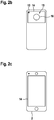
- FIG. 2b shows the portable electronic module 2 from the FIG. 2a in a rear view.
- the portable electronic module 2 has a camera unit 15.
- the camera unit 15 further has a camera lens 16 which is arranged on the rear side of the portable electronic module.
- the camera unit is used to record images by means of the portable electronic module 2.
- the camera unit 15 further comprises a flash of light source 17, which can be used to record images by means of the camera unit in poor and / or dark light conditions. Contrary to the actual task as a flash of light in camera shots, flash source 17 is configured to form the light-emitting unit 10.
- the flash of light source 17 is data-technologically connected to the coding unit 9, wherein the coding unit 9 provides the coded acknowledgment data of the flash of light source 17, wherein the flash of light source 17 is adapted to radiate the coded acknowledgment data in the form of a coded light signal.
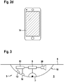
- the Figure 2c shows the portable electronic module 2 from the FIGS. 2a and 2 B in a view in which the display unit 14 is in maximum brightness.
- the display unit 14 is configured in the state of maximum brightness such that each pixel of the display unit 14 emits light of maximum intensity, preferably white light of maximum intensity.
- Figure 2d shows the portable electronics module Figure 2c , wherein the display unit 14 is here in a dark operating state.
- the dark operating state of the display unit 14 is formed in particular in that each pixel of the display unit 14 is present as a black pixel.
- the display unit 14 can be connected to the coding unit 9 in terms of data, wherein the display unit 14 can form the light-emitting unit 10, the emitting of the coded light signal being effected by the display unit 14, the display unit 14 for emitting the light signal 11 between bright operating state and dark operating state changes.
- FIG. 3 shows a detailed view of a reporting module 3.
- the signaling module 3 comprises a housing 18, wherein the signaling module 3 is arranged with the housing 18 on the ceiling 6 of the monitoring area 5.
- the reporting module 3 comprises a radio interface 19 and an alarm output unit 20.
- the radio interface 19 is for example a WLAN, a Bluetooth or an infrared interface, the radio interface 19 in particular data technology can be coupled to a wireless counter interface portable electronic module 2.
- Auxiliary data can be interchanged between the portable electronic module 2 and the reporting module 3 by means of the radio interface 19, the auxiliary data comprising additional information for decoding and / or coding the acknowledgment data.
- the auxiliary data comprises the coding key and / or the decoding key.
- the radio interface 19 is connected to the decoding device 13 and / or the control device 8 in terms of data technology.
- the radio interface 19 provides the auxiliary data of the decoding device 13 and / or the control device 8.
- the alarm output unit 20 is data-technologically connected to the control unit 8, the control unit 8 providing and / or reporting the alarm status in terms of data to the alarm output unit 20, wherein the alarm output unit 20 is configured in the alarm status to output an audible and / or visual alarm. In the normal state, the alarm output unit 20 is in an idle state and in this case does not issue an audible alarm and / or an optical alarm.
Landscapes
- Physics & Mathematics (AREA)
- General Physics & Mathematics (AREA)
- Business, Economics & Management (AREA)
- Emergency Management (AREA)
- Engineering & Computer Science (AREA)
- Computer Security & Cryptography (AREA)
- Alarm Systems (AREA)
Applications Claiming Priority (1)
| Application Number | Priority Date | Filing Date | Title |
|---|---|---|---|
| DE102016226133.9A DE102016226133A1 (de) | 2016-12-23 | 2016-12-23 | Sender-Empfänger-Vorrichtung, Meldemodul, tragbares Elektronikmodul, Verfahren zum berührungslosen Deaktivieren eines Alarmzustandes eines Meldemoduls und Computerprogramm |
Publications (2)
| Publication Number | Publication Date |
|---|---|
| EP3340199A1 true EP3340199A1 (fr) | 2018-06-27 |
| EP3340199B1 EP3340199B1 (fr) | 2021-02-17 |
Family
ID=60673580
Family Applications (1)
| Application Number | Title | Priority Date | Filing Date |
|---|---|---|---|
| EP17207362.9A Active EP3340199B1 (fr) | 2016-12-23 | 2017-12-14 | Dispositif émetteur-récepteur, module de notification, procédé de désactivation sans contact d'un état d'alarme d'un module de notification et programme informatique |
Country Status (2)
| Country | Link |
|---|---|
| EP (1) | EP3340199B1 (fr) |
| DE (1) | DE102016226133A1 (fr) |
Families Citing this family (1)
| Publication number | Priority date | Publication date | Assignee | Title |
|---|---|---|---|---|
| DE102022105018A1 (de) * | 2022-03-03 | 2023-09-07 | TRUMPF Werkzeugmaschinen SE + Co. KG | Verfahren und System zur Freigabe einer sicherheitskritischen Funktion einer Maschine |
Citations (5)
| Publication number | Priority date | Publication date | Assignee | Title |
|---|---|---|---|---|
| US20070080819A1 (en) * | 2005-10-12 | 2007-04-12 | Marks Mitchell J | Smoke detector with remote alarm silencing means |
| EP2555176A1 (fr) * | 2011-08-04 | 2013-02-06 | Atral-Secal GmbH | Dispositif de détection d'incendies |
| DE102012201589A1 (de) | 2012-02-03 | 2013-08-08 | Robert Bosch Gmbh | Brandmelder mit Mensch-Maschinen-Schnittstelle sowie Verfahren zur Steuerung des Brandmelders |
| US20160181787A1 (en) * | 2010-10-04 | 2016-06-23 | Thorn Security Limited | Isolator Circuit |
| US20160328935A1 (en) * | 2015-05-06 | 2016-11-10 | Siemens Schweiz Ag | Open Scattered Light Smoke Detector Together With A Mobile Communication Device For Such An Open Scattered Light Smoke Detector For The Reception Of Detector Data And For Transmitting Update Data |
-
2016
- 2016-12-23 DE DE102016226133.9A patent/DE102016226133A1/de not_active Withdrawn
-
2017
- 2017-12-14 EP EP17207362.9A patent/EP3340199B1/fr active Active
Patent Citations (5)
| Publication number | Priority date | Publication date | Assignee | Title |
|---|---|---|---|---|
| US20070080819A1 (en) * | 2005-10-12 | 2007-04-12 | Marks Mitchell J | Smoke detector with remote alarm silencing means |
| US20160181787A1 (en) * | 2010-10-04 | 2016-06-23 | Thorn Security Limited | Isolator Circuit |
| EP2555176A1 (fr) * | 2011-08-04 | 2013-02-06 | Atral-Secal GmbH | Dispositif de détection d'incendies |
| DE102012201589A1 (de) | 2012-02-03 | 2013-08-08 | Robert Bosch Gmbh | Brandmelder mit Mensch-Maschinen-Schnittstelle sowie Verfahren zur Steuerung des Brandmelders |
| US20160328935A1 (en) * | 2015-05-06 | 2016-11-10 | Siemens Schweiz Ag | Open Scattered Light Smoke Detector Together With A Mobile Communication Device For Such An Open Scattered Light Smoke Detector For The Reception Of Detector Data And For Transmitting Update Data |
Also Published As
| Publication number | Publication date |
|---|---|
| EP3340199B1 (fr) | 2021-02-17 |
| DE102016226133A1 (de) | 2018-06-28 |
Similar Documents
| Publication | Publication Date | Title |
|---|---|---|
| US20140313032A1 (en) | System and methods for notifying a community of security events | |
| US20170313247A1 (en) | Vehicle safety system | |
| JP4996491B2 (ja) | 撮像装置 | |
| KR101637007B1 (ko) | 위급상황 모니터링 시스템 | |
| DE10358637A1 (de) | Drahtloser Bewegungsmelder und in ein drahtloses Telefon integrierte Kamera | |
| KR101737380B1 (ko) | 오토리프트, 카메라 및 감지장치를 이용한 모니터링 시스템 | |
| KR102015081B1 (ko) | IoT 기반 지하주차장의 비상벨 시스템 | |
| EP3340199B1 (fr) | Dispositif émetteur-récepteur, module de notification, procédé de désactivation sans contact d'un état d'alarme d'un module de notification et programme informatique | |
| EP2880673B1 (fr) | Dispositif de commutation comportant un module radio et fonction de désactivation | |
| US20110080292A1 (en) | Security Device and Security System | |
| KR101638513B1 (ko) | 지그비 수신장치를 탑재한 아이피 카메라 시스템 | |
| WO2017102999A1 (fr) | Dispositif d'alarme | |
| CN105844827A (zh) | 入侵报警系统 | |
| DE202015105334U1 (de) | Modular aufgebaute in ein Gehäuse integrierte Sicherheitsleuchte | |
| KR101358446B1 (ko) | 교도소용 수감자 감시시스템 | |
| TWM464777U (zh) | 監控裝置 | |
| KR101567583B1 (ko) | 영상촬영 기능을 갖는 방범창 | |
| KR101879505B1 (ko) | 기상 조건에 대응하여 가변하는 감성 색상을 표출할 수 있는 조명부를 갖는 가정용 cctv | |
| EP3208953A1 (fr) | Système de transmission de données sans fil dans un système d'installation de bâtiment ou de maison | |
| KR20130001077A (ko) | 도난 방지용 네트워크 카메라 | |
| DE102014220553A1 (de) | Multifunktionseinheit und Objektüberwachungssystem | |
| WO2007077474A1 (fr) | Nouvelle conception 2 | |
| JP6564487B1 (ja) | 映像監視装置 | |
| JPH11154287A (ja) | 緊急監視装置 | |
| CN205508031U (zh) | 一种红外线报警器 |
Legal Events
| Date | Code | Title | Description |
|---|---|---|---|
| PUAI | Public reference made under article 153(3) epc to a published international application that has entered the european phase |
Free format text: ORIGINAL CODE: 0009012 |
|
| STAA | Information on the status of an ep patent application or granted ep patent |
Free format text: STATUS: THE APPLICATION HAS BEEN PUBLISHED |
|
| AK | Designated contracting states |
Kind code of ref document: A1 Designated state(s): AL AT BE BG CH CY CZ DE DK EE ES FI FR GB GR HR HU IE IS IT LI LT LU LV MC MK MT NL NO PL PT RO RS SE SI SK SM TR |
|
| AX | Request for extension of the european patent |
Extension state: BA ME |
|
| STAA | Information on the status of an ep patent application or granted ep patent |
Free format text: STATUS: REQUEST FOR EXAMINATION WAS MADE |
|
| 17P | Request for examination filed |
Effective date: 20190102 |
|
| RBV | Designated contracting states (corrected) |
Designated state(s): AL AT BE BG CH CY CZ DE DK EE ES FI FR GB GR HR HU IE IS IT LI LT LU LV MC MK MT NL NO PL PT RO RS SE SI SK SM TR |
|
| STAA | Information on the status of an ep patent application or granted ep patent |
Free format text: STATUS: EXAMINATION IS IN PROGRESS |
|
| 17Q | First examination report despatched |
Effective date: 20190625 |
|
| RAP1 | Party data changed (applicant data changed or rights of an application transferred) |
Owner name: ROBERT BOSCH GMBH |
|
| RIC1 | Information provided on ipc code assigned before grant |
Ipc: G08B 29/04 20060101ALI20200520BHEP Ipc: G08B 17/00 20060101AFI20200520BHEP Ipc: G08B 25/00 20060101ALN20200520BHEP |
|
| GRAP | Despatch of communication of intention to grant a patent |
Free format text: ORIGINAL CODE: EPIDOSNIGR1 |
|
| STAA | Information on the status of an ep patent application or granted ep patent |
Free format text: STATUS: GRANT OF PATENT IS INTENDED |
|
| RIC1 | Information provided on ipc code assigned before grant |
Ipc: G08B 25/00 20060101ALN20200616BHEP Ipc: G08B 29/04 20060101ALI20200616BHEP Ipc: G08B 17/00 20060101AFI20200616BHEP |
|
| RIC1 | Information provided on ipc code assigned before grant |
Ipc: G08B 25/00 20060101ALN20200626BHEP Ipc: G08B 29/04 20060101ALI20200626BHEP Ipc: G08B 17/00 20060101AFI20200626BHEP |
|
| INTG | Intention to grant announced |
Effective date: 20200717 |
|
| GRAS | Grant fee paid |
Free format text: ORIGINAL CODE: EPIDOSNIGR3 |
|
| GRAA | (expected) grant |
Free format text: ORIGINAL CODE: 0009210 |
|
| STAA | Information on the status of an ep patent application or granted ep patent |
Free format text: STATUS: THE PATENT HAS BEEN GRANTED |
|
| AK | Designated contracting states |
Kind code of ref document: B1 Designated state(s): AL AT BE BG CH CY CZ DE DK EE ES FI FR GB GR HR HU IE IS IT LI LT LU LV MC MK MT NL NO PL PT RO RS SE SI SK SM TR |
|
| REG | Reference to a national code |
Ref country code: GB Ref legal event code: FG4D Free format text: NOT ENGLISH |
|
| REG | Reference to a national code |
Ref country code: CH Ref legal event code: EP |
|
| REG | Reference to a national code |
Ref country code: DE Ref legal event code: R096 Ref document number: 502017009332 Country of ref document: DE |
|
| REG | Reference to a national code |
Ref country code: AT Ref legal event code: REF Ref document number: 1362497 Country of ref document: AT Kind code of ref document: T Effective date: 20210315 |
|
| REG | Reference to a national code |
Ref country code: IE Ref legal event code: FG4D Free format text: LANGUAGE OF EP DOCUMENT: GERMAN |
|
| REG | Reference to a national code |
Ref country code: LT Ref legal event code: MG9D |
|
| REG | Reference to a national code |
Ref country code: NL Ref legal event code: MP Effective date: 20210217 |
|
| PG25 | Lapsed in a contracting state [announced via postgrant information from national office to epo] |
Ref country code: GR Free format text: LAPSE BECAUSE OF FAILURE TO SUBMIT A TRANSLATION OF THE DESCRIPTION OR TO PAY THE FEE WITHIN THE PRESCRIBED TIME-LIMIT Effective date: 20210518 Ref country code: FI Free format text: LAPSE BECAUSE OF FAILURE TO SUBMIT A TRANSLATION OF THE DESCRIPTION OR TO PAY THE FEE WITHIN THE PRESCRIBED TIME-LIMIT Effective date: 20210217 Ref country code: HR Free format text: LAPSE BECAUSE OF FAILURE TO SUBMIT A TRANSLATION OF THE DESCRIPTION OR TO PAY THE FEE WITHIN THE PRESCRIBED TIME-LIMIT Effective date: 20210217 Ref country code: NO Free format text: LAPSE BECAUSE OF FAILURE TO SUBMIT A TRANSLATION OF THE DESCRIPTION OR TO PAY THE FEE WITHIN THE PRESCRIBED TIME-LIMIT Effective date: 20210517 Ref country code: PT Free format text: LAPSE BECAUSE OF FAILURE TO SUBMIT A TRANSLATION OF THE DESCRIPTION OR TO PAY THE FEE WITHIN THE PRESCRIBED TIME-LIMIT Effective date: 20210617 Ref country code: BG Free format text: LAPSE BECAUSE OF FAILURE TO SUBMIT A TRANSLATION OF THE DESCRIPTION OR TO PAY THE FEE WITHIN THE PRESCRIBED TIME-LIMIT Effective date: 20210517 Ref country code: LT Free format text: LAPSE BECAUSE OF FAILURE TO SUBMIT A TRANSLATION OF THE DESCRIPTION OR TO PAY THE FEE WITHIN THE PRESCRIBED TIME-LIMIT Effective date: 20210217 |
|
| PG25 | Lapsed in a contracting state [announced via postgrant information from national office to epo] |
Ref country code: RS Free format text: LAPSE BECAUSE OF FAILURE TO SUBMIT A TRANSLATION OF THE DESCRIPTION OR TO PAY THE FEE WITHIN THE PRESCRIBED TIME-LIMIT Effective date: 20210217 Ref country code: PL Free format text: LAPSE BECAUSE OF FAILURE TO SUBMIT A TRANSLATION OF THE DESCRIPTION OR TO PAY THE FEE WITHIN THE PRESCRIBED TIME-LIMIT Effective date: 20210217 Ref country code: LV Free format text: LAPSE BECAUSE OF FAILURE TO SUBMIT A TRANSLATION OF THE DESCRIPTION OR TO PAY THE FEE WITHIN THE PRESCRIBED TIME-LIMIT Effective date: 20210217 Ref country code: NL Free format text: LAPSE BECAUSE OF FAILURE TO SUBMIT A TRANSLATION OF THE DESCRIPTION OR TO PAY THE FEE WITHIN THE PRESCRIBED TIME-LIMIT Effective date: 20210217 Ref country code: SE Free format text: LAPSE BECAUSE OF FAILURE TO SUBMIT A TRANSLATION OF THE DESCRIPTION OR TO PAY THE FEE WITHIN THE PRESCRIBED TIME-LIMIT Effective date: 20210217 |
|
| PG25 | Lapsed in a contracting state [announced via postgrant information from national office to epo] |
Ref country code: IS Free format text: LAPSE BECAUSE OF FAILURE TO SUBMIT A TRANSLATION OF THE DESCRIPTION OR TO PAY THE FEE WITHIN THE PRESCRIBED TIME-LIMIT Effective date: 20210617 |
|
| PG25 | Lapsed in a contracting state [announced via postgrant information from national office to epo] |
Ref country code: CZ Free format text: LAPSE BECAUSE OF FAILURE TO SUBMIT A TRANSLATION OF THE DESCRIPTION OR TO PAY THE FEE WITHIN THE PRESCRIBED TIME-LIMIT Effective date: 20210217 Ref country code: EE Free format text: LAPSE BECAUSE OF FAILURE TO SUBMIT A TRANSLATION OF THE DESCRIPTION OR TO PAY THE FEE WITHIN THE PRESCRIBED TIME-LIMIT Effective date: 20210217 Ref country code: SM Free format text: LAPSE BECAUSE OF FAILURE TO SUBMIT A TRANSLATION OF THE DESCRIPTION OR TO PAY THE FEE WITHIN THE PRESCRIBED TIME-LIMIT Effective date: 20210217 |
|
| REG | Reference to a national code |
Ref country code: DE Ref legal event code: R097 Ref document number: 502017009332 Country of ref document: DE |
|
| PG25 | Lapsed in a contracting state [announced via postgrant information from national office to epo] |
Ref country code: RO Free format text: LAPSE BECAUSE OF FAILURE TO SUBMIT A TRANSLATION OF THE DESCRIPTION OR TO PAY THE FEE WITHIN THE PRESCRIBED TIME-LIMIT Effective date: 20210217 Ref country code: SK Free format text: LAPSE BECAUSE OF FAILURE TO SUBMIT A TRANSLATION OF THE DESCRIPTION OR TO PAY THE FEE WITHIN THE PRESCRIBED TIME-LIMIT Effective date: 20210217 Ref country code: DK Free format text: LAPSE BECAUSE OF FAILURE TO SUBMIT A TRANSLATION OF THE DESCRIPTION OR TO PAY THE FEE WITHIN THE PRESCRIBED TIME-LIMIT Effective date: 20210217 |
|
| PLBE | No opposition filed within time limit |
Free format text: ORIGINAL CODE: 0009261 |
|
| STAA | Information on the status of an ep patent application or granted ep patent |
Free format text: STATUS: NO OPPOSITION FILED WITHIN TIME LIMIT |
|
| 26N | No opposition filed |
Effective date: 20211118 |
|
| PG25 | Lapsed in a contracting state [announced via postgrant information from national office to epo] |
Ref country code: ES Free format text: LAPSE BECAUSE OF FAILURE TO SUBMIT A TRANSLATION OF THE DESCRIPTION OR TO PAY THE FEE WITHIN THE PRESCRIBED TIME-LIMIT Effective date: 20210217 Ref country code: AL Free format text: LAPSE BECAUSE OF FAILURE TO SUBMIT A TRANSLATION OF THE DESCRIPTION OR TO PAY THE FEE WITHIN THE PRESCRIBED TIME-LIMIT Effective date: 20210217 |
|
| PG25 | Lapsed in a contracting state [announced via postgrant information from national office to epo] |
Ref country code: SI Free format text: LAPSE BECAUSE OF FAILURE TO SUBMIT A TRANSLATION OF THE DESCRIPTION OR TO PAY THE FEE WITHIN THE PRESCRIBED TIME-LIMIT Effective date: 20210217 |
|
| PG25 | Lapsed in a contracting state [announced via postgrant information from national office to epo] |
Ref country code: IT Free format text: LAPSE BECAUSE OF FAILURE TO SUBMIT A TRANSLATION OF THE DESCRIPTION OR TO PAY THE FEE WITHIN THE PRESCRIBED TIME-LIMIT Effective date: 20210217 |
|
| PG25 | Lapsed in a contracting state [announced via postgrant information from national office to epo] |
Ref country code: IS Free format text: LAPSE BECAUSE OF FAILURE TO SUBMIT A TRANSLATION OF THE DESCRIPTION OR TO PAY THE FEE WITHIN THE PRESCRIBED TIME-LIMIT Effective date: 20210617 |
|
| PG25 | Lapsed in a contracting state [announced via postgrant information from national office to epo] |
Ref country code: MC Free format text: LAPSE BECAUSE OF FAILURE TO SUBMIT A TRANSLATION OF THE DESCRIPTION OR TO PAY THE FEE WITHIN THE PRESCRIBED TIME-LIMIT Effective date: 20210217 |
|
| REG | Reference to a national code |
Ref country code: CH Ref legal event code: PL |
|
| REG | Reference to a national code |
Ref country code: BE Ref legal event code: MM Effective date: 20211231 |
|
| PG25 | Lapsed in a contracting state [announced via postgrant information from national office to epo] |
Ref country code: LU Free format text: LAPSE BECAUSE OF NON-PAYMENT OF DUE FEES Effective date: 20211214 Ref country code: IE Free format text: LAPSE BECAUSE OF NON-PAYMENT OF DUE FEES Effective date: 20211214 |
|
| PG25 | Lapsed in a contracting state [announced via postgrant information from national office to epo] |
Ref country code: BE Free format text: LAPSE BECAUSE OF NON-PAYMENT OF DUE FEES Effective date: 20211231 |
|
| PG25 | Lapsed in a contracting state [announced via postgrant information from national office to epo] |
Ref country code: LI Free format text: LAPSE BECAUSE OF NON-PAYMENT OF DUE FEES Effective date: 20211231 Ref country code: CH Free format text: LAPSE BECAUSE OF NON-PAYMENT OF DUE FEES Effective date: 20211231 |
|
| PG25 | Lapsed in a contracting state [announced via postgrant information from national office to epo] |
Ref country code: HU Free format text: LAPSE BECAUSE OF FAILURE TO SUBMIT A TRANSLATION OF THE DESCRIPTION OR TO PAY THE FEE WITHIN THE PRESCRIBED TIME-LIMIT; INVALID AB INITIO Effective date: 20171214 |
|
| PG25 | Lapsed in a contracting state [announced via postgrant information from national office to epo] |
Ref country code: CY Free format text: LAPSE BECAUSE OF FAILURE TO SUBMIT A TRANSLATION OF THE DESCRIPTION OR TO PAY THE FEE WITHIN THE PRESCRIBED TIME-LIMIT Effective date: 20210217 |
|
| REG | Reference to a national code |
Ref country code: AT Ref legal event code: MM01 Ref document number: 1362497 Country of ref document: AT Kind code of ref document: T Effective date: 20221214 |
|
| PG25 | Lapsed in a contracting state [announced via postgrant information from national office to epo] |
Ref country code: AT Free format text: LAPSE BECAUSE OF NON-PAYMENT OF DUE FEES Effective date: 20221214 |
|
| PG25 | Lapsed in a contracting state [announced via postgrant information from national office to epo] |
Ref country code: MK Free format text: LAPSE BECAUSE OF FAILURE TO SUBMIT A TRANSLATION OF THE DESCRIPTION OR TO PAY THE FEE WITHIN THE PRESCRIBED TIME-LIMIT Effective date: 20210217 Ref country code: AT Free format text: LAPSE BECAUSE OF NON-PAYMENT OF DUE FEES Effective date: 20221214 |
|
| PG25 | Lapsed in a contracting state [announced via postgrant information from national office to epo] |
Ref country code: TR Free format text: LAPSE BECAUSE OF FAILURE TO SUBMIT A TRANSLATION OF THE DESCRIPTION OR TO PAY THE FEE WITHIN THE PRESCRIBED TIME-LIMIT Effective date: 20210217 |
|
| PG25 | Lapsed in a contracting state [announced via postgrant information from national office to epo] |
Ref country code: MT Free format text: LAPSE BECAUSE OF FAILURE TO SUBMIT A TRANSLATION OF THE DESCRIPTION OR TO PAY THE FEE WITHIN THE PRESCRIBED TIME-LIMIT Effective date: 20210217 |
|
| PGFP | Annual fee paid to national office [announced via postgrant information from national office to epo] |
Ref country code: GB Payment date: 20251218 Year of fee payment: 9 |
|
| PGFP | Annual fee paid to national office [announced via postgrant information from national office to epo] |
Ref country code: FR Payment date: 20251218 Year of fee payment: 9 |
|
| PGFP | Annual fee paid to national office [announced via postgrant information from national office to epo] |
Ref country code: DE Payment date: 20260223 Year of fee payment: 9 |
|
| PGFP | Annual fee paid to national office [announced via postgrant information from national office to epo] |
Ref country code: AT Payment date: 20260410 Year of fee payment: 5 |