EP3340199B1 - Dispositif émetteur-récepteur, module de notification, procédé de désactivation sans contact d'un état d'alarme d'un module de notification et programme informatique - Google Patents
Dispositif émetteur-récepteur, module de notification, procédé de désactivation sans contact d'un état d'alarme d'un module de notification et programme informatique Download PDFInfo
- Publication number
- EP3340199B1 EP3340199B1 EP17207362.9A EP17207362A EP3340199B1 EP 3340199 B1 EP3340199 B1 EP 3340199B1 EP 17207362 A EP17207362 A EP 17207362A EP 3340199 B1 EP3340199 B1 EP 3340199B1
- Authority
- EP
- European Patent Office
- Prior art keywords
- module
- unit
- light
- light signal
- data
- Prior art date
- Legal status (The legal status is an assumption and is not a legal conclusion. Google has not performed a legal analysis and makes no representation as to the accuracy of the status listed.)
- Active
Links
Images


Classifications
-
- G—PHYSICS
- G08—SIGNALLING
- G08B—SIGNALLING SYSTEMS, e.g. PERSONAL CALLING SYSTEMS; ORDER TELEGRAPHS; ALARM SYSTEMS
- G08B29/00—Checking or monitoring of signalling or alarm systems; Prevention or correction of operating errors, e.g. preventing unauthorised operation
- G08B29/02—Monitoring continuously signalling or alarm systems
- G08B29/04—Monitoring of the detection circuits
- G08B29/043—Monitoring of the detection circuits of fire detection circuits
-
- G—PHYSICS
- G08—SIGNALLING
- G08B—SIGNALLING SYSTEMS, e.g. PERSONAL CALLING SYSTEMS; ORDER TELEGRAPHS; ALARM SYSTEMS
- G08B17/00—Fire alarms; Alarms responsive to explosion
-
- G—PHYSICS
- G08—SIGNALLING
- G08B—SIGNALLING SYSTEMS, e.g. PERSONAL CALLING SYSTEMS; ORDER TELEGRAPHS; ALARM SYSTEMS
- G08B25/00—Alarm systems in which the location of the alarm condition is signalled to a central station, e.g. fire or police telegraphic systems
- G08B25/001—Alarm cancelling procedures or alarm forwarding decisions, e.g. based on absence of alarm confirmation
Definitions
- a triggered alarm can be reset directly on the detector if at least one line of sight to the detector is available. Resetting is usually done using a push button, the push button being installed directly on the detector. Since the detectors are often mounted on the ceilings of a room, it is difficult for a person to reach the push button easily and / or without further aids.
- the pamphlet DE 10 2012 201 589 A1 describes a fire alarm with a fire sensor device for detecting a fire and for outputting a fire signal, with an environmental sensor device for detecting bodies in the vicinity of the fire alarm and for outputting an environmental signal, with a control device which, depending on the fire signal, sets a normal state and an alarm state of the fire alarm sets, wherein the fire alarm is designed as a man-machine interface and the control device checks whether the ambient signal is to be evaluated as a user input.
- a device for detecting fires comprising an infrared receiver for receiving infrared signals with which a signal transmitter can be deactivated.
- a transmitter-receiver device having the features of claim 1 is proposed. Furthermore, a method for Contactless deactivation of an alarm state of a message module with the features of claim 11 and a computer program with the features of claim 12 are proposed. Preferred and / or advantageous embodiments of the invention emerge from the subclaims, the following description and the attached figures.
- a transmitter-receiver device comprises at least one portable electronic module as a transmitter and at least one signaling module as a receiver.
- the reporting module is in particular a stationary reporting module and, for example, a peripheral device.
- the reporting module is preferably designed to output an alarm, in particular to output an acoustic and / or visual alarm.
- the electronics module is in particular a hand-held device for a person and / or a user.
- the reporting module is preferably designed as a receiver to interact and / or couple with a plurality of transmitters, in particular portable electronic modules.
- the portable electronics module is preferably designed to interact and / or couple with a plurality of signaling modules.
- the signaling module can be arranged in a monitoring area.
- the monitoring area is, for example, a building, in particular a house, a factory and / or an airport.
- the reporting module can be arranged and / or arranged, for example, on the wall and / or on the ceiling of the monitoring area.
- the reporting module is preferably designed to monitor the surveillance area in terms of safety.
- the reporting module comprises a detection device and a control device.
- the control device and the detection device preferably form a common central computer device.
- the detection device and control device are connected to one another in terms of data technology.
- the detection device is designed to detect an event in the monitoring area.
- the detection device comprises a sensor for detecting the event and a detection evaluation device for determining and detecting the event based on the sensor data.
- the An event is, for example, a fire, movement, ingress of water, a rise in temperature and / or a break-in in the monitoring area.
- the detection device is designed to provide the detected event to the control device in terms of data technology as event data.
- the event data are digital data; alternatively, the event data are analog data.
- the event data preferably include information on the type of event, the time of the event, an intensity of the event and / or a level strength of the detected event.
- the control device is designed to set the reporting module into an alarm state and into a normal state based on the event data. As long as the detection device does not detect an event in the monitoring area, it is assumed that there is no event in the monitoring area and thus the reporting module is in the normal state and / or is set. If an event is detected in the monitoring area by the detection device, the reporting module is set to the alarm state. As a reaction to the setting of the reporting module to the alarm state, an acoustic alarm signal is output and / or an alarm message, for example via a network, in particular a security network, is sent to a monitoring center, which can then take further measures.
- a network in particular a security network
- the portable electronics module comprises a coding unit and a light transmitting unit.
- the coding unit is preferably a microchip, a computer unit or a data technology application.
- the coding unit is designed to code acknowledgment data and to provide it to the light transmission unit.
- the coding unit is designed to code acknowledgment data according to a predetermined and / or adjustable protocol and / or coding key.
- the coded acknowledgment data are in particular digital data.
- the acknowledgment data are preferably provided by the user and / or include a command for the control device to switch the message module from the alarm state to the normal state.
- the light transmission unit is designed to emit light.
- the light transmission unit is a directed light source, for example with a predetermined emission direction.
- the light transmission unit is a point source and / or a flat light source.
- the light transmission unit is designed to output the coded acknowledgment data as a coded light signal.
- the coded light signal is an alternation of emission and not emission of light, in particular on / off of the light source.
- the time variation of the light signal in the intensity and / or the color of the light signal is preferably understood as a coded light signal.
- the coded light signal can be a specific shape and / or a specific coded pattern.
- the reporting module includes a light receiving unit and a decoding unit.
- the decoding unit comprises the light receiving unit.
- the light receiving unit is, for example, a photodiode and is designed to detect light and output it as a signal.
- the light receiving unit is designed to receive the encoded light signal of the portable electronic module.
- the light receiving unit is preferably designed to convert the received coded light signal into an electrical signal, in particular to convert it into a digital or analog signal and to provide it to the detection device in terms of data.
- the decoding unit is, for example, a computer device, a computer chip or a computer unit.
- the decoding unit is designed to decode the coded light signal provided by the light receiving unit and to provide it as acknowledgment data to the control device.
- the same coding key is used for decoding the light signal as is used for coding the acknowledgment data by the coding unit.
- the decoded acknowledgment data correspond to the unacknowledged acknowledgment data that were coded by the coding unit.
- the control module is designed to set the message module from the alarm state to the normal state based on the acknowledgment data.
- the control module is designed to switch the message module from the alarm state to the normal state only for a specific acknowledgment data record set, wherein the acknowledgment data record is part of the acknowledgment data and comprises an instruction and / or a command for setting the normal state of the message module.
- the control module is designed to switch the reporting module from the alarm state to the normal state if the acknowledgment data include the information that there is no event in the monitoring area and / or that the event is a false alarm.
- the invention has the advantage that a transmitter-receiver device is provided which enables the contactless acknowledgment of the alarm and / or the contactless resetting of a reporting module in a monitoring area.
- the acknowledgment is secure against an incorrect acknowledgment of the alarm, since, for example, only a certain group of people can acknowledge the alarm through the use of portable electronic modules.
- the coded light signal is a light signal in the visible wavelength range.
- the light signal is preferably a light signal from a thermal light source; alternatively and / or in addition, the light signal is a light signal from a non-thermal light source.
- the light signal is preferably a white light light signal, alternatively the light signal is a color light signal, such as a blue or red light signal.
- the coded light signal is preferably a light signal which has been coded and / or encrypted based on the RC5, the RC6, the RECS80, the NEC or the RCMM code.
- This refinement is based on the consideration of using a light signal and / or a light source for the transmitter-receiver device that is specially adapted to the area of application of the receiver, in particular of the reporting module.
- the reporting module has a radio interface and the portable electronics module has a radio counter-interface.
- the radio interface and radio counter-interface are preferably a WLAN interface, Bluetooth interface, IR interface or other radio interface.
- the radio interface and radio counter-interface can be coupled to one another in terms of data technology, with auxiliary data being exchangeable by means of the data-technical coupling of the radio interface with the radio counter-interface.
- the auxiliary data can be exchanged from the radio interface towards the radio counter-interface and / or from the radio counter-interface towards the radio interface.
- the auxiliary data include information for the verification of a switchover of the signaling module from the alarm state to the normal state.
- the auxiliary data include the ID of the user and / or the ID of the electronic module, the control module, for example, being designed to switch the signaling module from the alarm state to the normal state only if the ID of the user and / or the ID of the electronic module is stored and / or is authorized to do so.
- the auxiliary data include the ID of the reporter, for example the ID of the reporter is required to generate the key and / or the protocol.
- the auxiliary data it is particularly possible for the auxiliary data to include information that the coded light signal is being sent and / or the light source is active, so that, for example, the control module is designed to activate the light receiving unit to receive the coded light signal. This refinement is based on the consideration of providing a transceiver device which reduces the false detection rate of switching off and / or acknowledging an alarm.
- the auxiliary data include coding and / or decoding information.
- the auxiliary data include the key, the coding key and / or the protocol for coding and / or decoding the light signal.
- the auxiliary data are designed to transfer the protocol and / or the key from the reporting module to the portable electronics module and / or vice versa.
- the key and / or the protocol is a dynamic key and / or a dynamic protocol. This refinement is based on the idea of providing a particularly attack-proof coding and / or decoding method for the transmitter / receiver device.
- the reporting module can be arranged in a monitoring area, for example a house, in particular on a wall and / or a ceiling of the monitoring area.
- the reporting module comprises a detection device and a control device.
- the detection device is designed to detect an event, for example a fire and / or a break-in, in the monitoring area and to provide the control device with the detected event as event data.
- the reporting module includes a light receiving unit and a decoding unit.
- the light receiving unit is preferably part of the decoding unit.
- the light receiving unit is a photosensitive device such as a photodiode.
- the light receiving unit is designed to receive a coded light signal and to provide the detection device with data.
- the encoded light signal is provided to the detection device as an analog electrical signal and / or as a digital electrical signal.
- the decoding unit is designed to decode the light signal and provide it as acknowledgment data to the control device.
- the control module is designed to set the message module from the alarm state to the normal state based on the acknowledgment data.
- the control module is designed to switch the reporting module from the alarm state to the normal state in the event that the acknowledgment data include information that the detected event is a false alarm and / or information that the alarm state should be actively set to the normal state.
- This invention is based on the idea of providing a signaling module which can be set from an alarm state to a normal state without contact by means of a transmitter device, so that a false alarm can be acknowledged.
- the light receiving unit comprises a daylight filter.
- the daylight filter is designed in particular to filter out light in the wavelength range outside the visible light range and to allow only light in the visible wavelength range to pass.
- This refinement is based on the idea of providing a reporting module that is not susceptible to the reception of light signals that do not represent coded light signals.
- the reporting module is a fire alarm and / or a motion alarm.
- the signaling module is a smoke detector that can detect a fire in the monitored area based on smoke parameters.
- the reporting module is also possible for the reporting module to be a fire detector that detects a fire in the monitoring area based on fire characteristics such as light emission and / or temperature rise.
- a reporting module designed as a motion detector is designed, for example, to detect movements in the monitored area and thus, for example, to detect unauthorized access and / or a break-in.
- the portable electronics module is designed in particular for the transmitter-receiver device.
- the portable electronic module comprises a coding unit and a light transmitting unit.
- the coding unit is designed to code acknowledgment data and provide it to the light transmitter unit.
- the light transmission unit is designed to output the coded acknowledgment data as a coded light signal.
- the portable electronics module is designed to send a coded light signal to a reporting module.
- the invention is based on the idea of providing a portable electronic module that can be coupled to signaling modules and encoded light signals are designed to deactivate a signaling module.
- the invention is based on the idea of providing a portable electronic module that enables a specific group of people to deactivate one and / or a plurality of reporting modules in the event of a false alarm.
- the portable electronics module comprises an LED and / or OLED.
- the LED is a single-color LED.
- the LED is an RGB LED.
- the LED forms the light transmission unit. This embodiment is based on the consideration that a portable electronics module, which for example a Flashlight application includes, can be used as a deactivation module of a reporting module.
- the electronics module comprises a camera unit for taking pictures.
- the camera unit preferably comprises a CCD or a CMOS camera.
- the camera further comprises a light flash source, the light flash source being designed to illuminate the object to be recorded with a light flash when taking pictures, in particular when the brightness of the surroundings is too low.
- the light flash source preferably forms the light transmission unit.
- the electronics module comprises a display unit for displaying text and / or images.
- the display unit is in particular an electronic display unit and, for example, an LED display, an OLED display and / or an LCD display.
- the display unit forms in particular the light transmission unit, the coded light signal being formed by a change between a light operating state of the display unit and a dark operating state of the display unit.
- the light operating state is a white display on the display unit and the dark operating state is a black display on the display unit.
- This refinement is based on the idea of using a screen display and / or a display of a portable electronic module instead of an incandescent lamp and / or an LED as the light source, with a large number of electronic modules being able to be used to deactivate a signaling module.
- the portable electronics module is a smartphone, a tablet computer, a phablet computer or some other type of mobile computer, with the coding of the light signal being stored in the electronics module as an application and / or as a program, for example. It is also possible that the portable electronic module is a remote control for controlling a television set, a hi-fi system and / or another electronic device. The remote control preferably uses one RC5 code. This refinement is based on the idea of creating a way that signaling modules with common electronic devices can be switched off in the event of a false alarm.
- Another object of the invention is a method for contactless deactivation of an alarm state of a message module.
- a portable electronic module is used to send a coded light signal to the reporting module, the reporting module preferably being in an alarm state.
- the reporting module receives the coded light signal and provides acknowledgment data based on the coded light signal.
- the reporting module is then set from the alarm state to the normal state when the acknowledgment data include the command that the reporting module is to be set to the normal state and / or that the alarm state corresponds to a false alarm.
- This invention is based on the idea of providing a method which makes it possible, in a quick and simple manner, to set a reporting module to a normal state in the event of a false alarm and thus to acknowledge the false alarm.
- Another object of the invention is a computer program with program means.
- the computer program provides that all steps for carrying out the method for contactless deactivation of an alarm state of a signaling module are carried out when the program is carried out on a computer, the portable electronic module and / or the signaling module.
- the computer program is, for example, an application for the portable electronics module, for example an application for a smartphone.
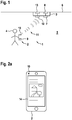
- Figure 1 shows a transmitter-receiver device 1 comprising a portable electronics module 2 as a transmitter and a stationary reporting module 3 as a receiver.
- the transmitter-receiver device 1 can include a plurality of portable electronic modules 2 as transmitters and a plurality of signaling modules 3 as receivers.
- the portable electronics module 2 as a transmitter is designed in particular to control the reporting module 3 and / or to interact with it.
- the portable electronics module 2 is preferably designed to exchange data with the reporting module 3.
- the portable electronic module 2 is designed for use by a person 4, the person 4 being able to carry the portable electronic module 2 with him, for example in a trouser pocket.
- the portable electronics module 2 preferably includes further functions that can be used by the person 4.
- the transmitter function represents only a secondary function of the portable electronics module 2.
- the portable electronics module 2 is, for example, a smartphone or a tablet computer.
- the reporting module 3 forms a receiver of the transmitter-receiver device 1.
- the reporting module 3 is, for example, a fire detector or a motion detector.
- the reporting module 3 is arranged in a monitoring area 5 in order to monitor it in terms of safety.
- the reporting module 3 is arranged on the ceiling 6 of the monitored area 5.
- the reporting module 3 comprises a detection device 7 which is designed to detect an event in the monitoring area 5.
- the detection device 7 is designed to be detected in the monitoring area 5 as a security-relevant event, such as a fire and / or a break-in.
- the detection device 7 is connected in terms of data technology to a control device 8, the detection device 7 being designed to provide a detected event in the monitoring area 5 as event data to the control device 8.
- the control device 8 is designed to set the reporting module 3 in an alarm state and / or in a normal state.
- the control device 8 is designed to set the reporting module 3 to the alarm state for a detected safety-relevant event in the monitoring area 5.
- the reporting module 3 is preferably in the normal state.
- the control device 8 sets the reporting module 3 to the alarm state, which corresponds to a false alarm.
- the false alarm is in particular and / or should in particular be able to be acknowledged by the person 4, the reporting module 3 being set from the alarm state to the normal state.
- the portable electronics module 2 comprises a coding unit 9.
- the coding unit 9 is designed to send the command to switch off the alarm state and or the command to switch from the alarm state to the normal state to a digital one To encode signal and / or a digital code.
- the portable electronics module comprises a light transmission unit 10, which is designed, for example, as a light-emitting diode.
- the light transmission unit 10 is connected to the coding unit 9 in terms of data.
- the light transmission unit 10 is designed to send and / or emit coded acknowledgment data in the form of a coded light signal 11.
- the coded acknowledgment data correspond in particular to acknowledgment data which, for example, include the command to change from the alarm state to the normal state, which were coded by the coding unit 9.
- the coded light signal 11 is, for example, a light signal with laterally fluctuating intensities of the radiation intensity, with a change in color composition over time and / or with a pattern that changes over time.
- the person 4 preferably positions himself so that the light-transmitting unit 10 is in direct line of sight to the reporting module 3.
- the reporting module 3 comprises a light receiving unit 12 which is designed to receive the coded light signal 11.
- the light receiving unit 12 is, for example, a photodiode.
- the light receiving unit 12 is designed to convert the coded light signal 11 into signal data, in particular electrical signal data, the electrical signal data being digital or analog electrical signals.
- the signal data of the light receiving unit 12 are provided to a decoding unit 13.
- the decoding unit 13 is in particular part of the message module 3.
- the decoding unit 13 is designed to decode the encoded light signal 11 received by the light receiving unit into decoded acknowledgment data.
- the decoded acknowledgment data include, in particular, the information that was sent by the portable electronics module 2 to the reporting module 3.
- the decoding unit 13 is connected to the control device 8 in terms of data.
- the control device 8 is designed to set the message module 3 from an alarm state to the normal state based on the decoded acknowledgment data, in particular when the decoded acknowledgment data includes the command to change from the alarm state to the normal state.
- FIG. 2a shows a detailed view of a portable electronic module 2 in a front view.
- the portable electronics module 2 is here a smartphone.
- the portable electronics module 2 comprises a light transmission unit 10, which is designed as an LED in this exemplary embodiment, the light transmission unit 10 having the actual function of a status display lamp of the portable electronics module 2.
- the portable electronics module 2 has a display unit 14.
- the display unit 14 is designed as a display, for example as an LCD or LED display.
- the display unit 14 is preferably used to display text and / or image information on the portable electronic module 2.
- the display unit 14 is designed as a controller and / or as an operating unit for operating the portable electronic module 2 by the person 4.
- the person 4 can For example, select a program and / or an application on the display unit, which encodes the information for acknowledging the alarm status of a message module 3, the acknowledgment data and provides the light transmitting unit 10 with data.
- the light transmitting unit 10 is designed to emit the coded acknowledgment data in the form of a coded light signal, the coded emitted light data being receivable by the light receiving unit 12 of the message module 3.
- FIG. 2b shows the portable electronics module 2 from FIG Figure 2a in a rear view.
- the portable electronics module 2 has a camera unit 15.
- the camera unit 15 furthermore has a camera lens 16 which is arranged on the rear side of the portable electronic module.
- the camera unit is used to record images by means of the portable electronics module 2.
- the camera unit 15 further comprises a light flash source 17, which can be used to record images by means of the camera unit in poor and / or dark lighting conditions. Contrary to the actual task as a flash of light in camera recordings, the light flash source 17 is designed to form the light transmitting unit 10.
- the light flash source 17 is connected to the coding unit 9 in terms of data, the coding unit 9 providing the coded acknowledgment data to the light flash source 17, the light flash source 17 being designed to emit the coded acknowledgment data in the form of a coded light signal.
- FIG. 2 shows the portable electronics module 2 from FIG Figures 2a and 2 B in a view in which the display unit 14 is at maximum brightness.
- the display unit 14 is designed in such a way that each pixel of the display unit 14 emits light with maximum intensity, preferably white light with maximum intensity.
- Figure 2d shows the portable electronics module Figure 2c , the display unit 14 being in a dark operating state here.
- the dark operating state of the display unit 14 is formed in particular by the fact that each pixel of the display unit 14 is present as a black pixel. It is thus possible for the display unit 14 to be connected to the coding unit 9 in terms of data technology, the display unit 14 being able to form the light transmitting unit 10, the coded light signal being emitted by the display unit 14, the display unit 14 for emitting the light signal 11 between light operating state and dark operating state changes.
- FIG. 3 shows a detailed view of a reporting module 3.
- the reporting module 3 comprises a housing 18, the reporting module 3 with the housing 18 being arranged on the ceiling 6 of the monitoring area 5.
- the reporting module 3 includes a radio interface 19 and an alarm output unit 20.
- the radio interface 19 is, for example, a WLAN, a Bluetooth or an infrared interface, the radio interface 19 being in particular for data purposes can be coupled to a radio interface of the portable electronics module 2.
- auxiliary data can be exchanged between the portable electronics module 2 and the message module 3, the auxiliary data including additional information for decoding and / or coding the acknowledgment data.
- the auxiliary data include the coding key and / or the decoding key.
- the radio interface 19 is connected to the decoding device 13 and / or the control device 8 in terms of data.
- the radio interface 19 provides the auxiliary data to the decoding device 13 and / or the control device 8.
- the alarm output unit 20 is connected in terms of data to the control device 8, the control device 8 providing and / or reporting the alarm state to the alarm output unit 20 in terms of data technology, the alarm output unit 20 being designed to output an acoustic and / or visual alarm in the alarm state. In the normal state, the alarm output unit 20 is in an idle state and does not output an acoustic alarm and / or a visual alarm.
Landscapes
- Physics & Mathematics (AREA)
- General Physics & Mathematics (AREA)
- Business, Economics & Management (AREA)
- Emergency Management (AREA)
- Engineering & Computer Science (AREA)
- Computer Security & Cryptography (AREA)
- Alarm Systems (AREA)
Claims (12)
- Dispositif émetteur-récepteur (1), comprenant un module électronique portable (2) en tant qu'émetteur et un module de notification (3) en tant que récepteur, dans lequel le module de notification (3) peut être disposé dans une zone de surveillance (5) et comprend un dispositif de détection (7) et un dispositif de commande (8), dans lequel le dispositif de détection (7) est conçu pour détecter un événement dans la zone de surveillance (5) et pour fournir au dispositif de commande (8) l'événement détecté en tant que données d'événement, dans lequel le dispositif de commande (8) est conçu pour faire passer le module de notification (3) dans un état d'alarme et un état normal sur la base des données d'événement,
dans lequel le module électronique portable (2) comprend une unité de codage (9) et une unité d'émission de lumière (10), dans lequel l'unité de codage (9) est conçue pour coder des données d'accusé de réception conformément à une clé de codage et pour les fournir à l'unité d'émission de lumière (10), dans lequel l'unité d'émission de lumière (10) est conçue pour délivrer les données d'accusé de réception codées sous la forme d'un signal lumineux codé (11),
dans lequel le module de notification (3) comprend une unité de réception de lumière (12) et une unité de décodage (13), dans lequel l'unité de réception de lumière (12) est conçue pour recevoir le signal lumineux codé (11) en provenance du module électronique portable (2) et pour les fournir à l'unité de décodage (13) par une technique de transmission de données,
dans lequel l'unité d'émission de lumière (10) est conçue pour émettre un signal lumineux (11) se situant dans la plage des longueurs d'onde visibles en tant que signal lumineux codé (11),
dans lequel l'unité de décodage (13) est conçue pour décoder le signal lumineux codé (11) et pour le fournir en tant que données d'accusé de réception au dispositif de commande (8), dans lequel la même clé de codage est utilisée pour le décodage du signal lumineux codé (11) que pour le codage par l'unité de codage (9),
dans lequel le dispositif de commande (8) est conçu pour faire passer le module de notification (3) de l'état d'alarme à l'état normal sur la base des données d'accusé de réception. - Dispositif émetteur-récepteur (1) selon la revendication 1, caractérisé en ce que le module de notification (3) possède une interface radio (19) et le module électronique portable (2) possède une interface radio complémentaire, dans lequel l'interface radio (19) et l'interface radio complémentaire peuvent être couplées par une technologie de transmission de données pour l'échange de données auxiliaires, dans lequel les données auxiliaires comprennent des informations permettant la vérification du passage du module de notification (3) de l'état d'alarme à l'état normal.
- Dispositif émetteur-récepteur (1) selon la revendication 2, caractérisé en ce que les données auxiliaires comprennent des informations de codage et/ou de décodage.
- Dispositif émetteur-récepteur (1) selon l'une des revendications précédentes, caractérisé en ce que le module électronique portable (2) comprend une LED, dans lequel la LED constitue l'unité d'émission de lumière (10) .
- Dispositif émetteur-récepteur (1) selon l'une des revendications précédentes, caractérisé en ce que le module électronique (2) comprend une unité à caméra (15) pour l'acquisition d'images, dans lequel l'unité à caméra (15) comprend une source de lumière à éclairs (17), dans lequel la source de lumière à éclairs (17) constitue l'unité d'émission de lumière (10).
- Dispositif émetteur-récepteur (1) selon l'une des revendications précédentes, caractérisé en ce que le module électronique (2) comprend une unité d'affichage (14) pour l'affichage de texte et/ou d'images, dans lequel l'unité d'affichage (14) constitue l'unité d'émission de lumière (10), dans lequel le signal lumineux codé (11) est constitué par un basculement entre un état de fonctionnement lumineux et un état de fonctionnement sombre de l'unité d'affichage (14).
- Dispositif émetteur-récepteur (1) selon l'une des revendications précédentes, caractérisé en ce que le module électronique (2) est un téléphone intelligent, un ordinateur tablette, un ordinateur phablette ou une télécommande pour la commande d'un téléviseur.
- Dispositif émetteur-récepteur (1) selon la revendication 1, caractérisé en ce que l'unité de réception de lumière (12) comprend un filtre de lumière du jour.
- Dispositif émetteur-récepteur (1) selon la revendication 8, caractérisé en ce que le filtre de lumière du jour est conçu pour filtrer la lumière dans une plage de longueurs d'onde située en dehors de la plage de lumière visible.
- Dispositif émetteur-récepteur (1) selon la revendication 1, caractérisé en ce que le module de notification (3) est un détecteur d'incendie ou un détecteur de mouvement.
- Procédé de désactivation sans contact d'un état d'alarme d'un module de notification (3), dans lequel un signal lumineux (11) codé conformément à une clé de codage est envoyé au module de notification (3) au moyen d'un module électronique portable (2),
dans lequel le signal lumineux codé (11) est un signal lumineux (11) se situant dans la plage des longueurs d'onde visibles,
dans lequel le module de notification (3) reçoit le signal lumineux codé (11), le décode et fournit des données d'accusé de réception sur la base du signal lumineux (11), dans lequel la même clé de codage est utilisée pour le décodage du signal lumineux codé (11) que pour le codage du signal lumineux (11),
dans lequel le module de notification (3) peut être et/ou est amené à passer de l'état d'alarme à l'état normal sur la base des données d'accusé de réception. - Programme d'ordinateur comprenant des moyens à code de programme pour l'exécution de toutes les étapes du procédé selon la revendication 11 lorsque ledit programme est exécuté sur un ordinateur.
Applications Claiming Priority (1)
| Application Number | Priority Date | Filing Date | Title |
|---|---|---|---|
| DE102016226133.9A DE102016226133A1 (de) | 2016-12-23 | 2016-12-23 | Sender-Empfänger-Vorrichtung, Meldemodul, tragbares Elektronikmodul, Verfahren zum berührungslosen Deaktivieren eines Alarmzustandes eines Meldemoduls und Computerprogramm |
Publications (2)
| Publication Number | Publication Date |
|---|---|
| EP3340199A1 EP3340199A1 (fr) | 2018-06-27 |
| EP3340199B1 true EP3340199B1 (fr) | 2021-02-17 |
Family
ID=60673580
Family Applications (1)
| Application Number | Title | Priority Date | Filing Date |
|---|---|---|---|
| EP17207362.9A Active EP3340199B1 (fr) | 2016-12-23 | 2017-12-14 | Dispositif émetteur-récepteur, module de notification, procédé de désactivation sans contact d'un état d'alarme d'un module de notification et programme informatique |
Country Status (2)
| Country | Link |
|---|---|
| EP (1) | EP3340199B1 (fr) |
| DE (1) | DE102016226133A1 (fr) |
Families Citing this family (1)
| Publication number | Priority date | Publication date | Assignee | Title |
|---|---|---|---|---|
| DE102022105018A1 (de) * | 2022-03-03 | 2023-09-07 | TRUMPF Werkzeugmaschinen SE + Co. KG | Verfahren und System zur Freigabe einer sicherheitskritischen Funktion einer Maschine |
Family Cites Families (5)
| Publication number | Priority date | Publication date | Assignee | Title |
|---|---|---|---|---|
| CA2625923A1 (fr) * | 2005-10-12 | 2007-04-19 | Global Zone, Llc | Detecteur de fumee comprenant des moyens de mise sous silence de l'alarme a distance |
| GB2484288A (en) * | 2010-10-04 | 2012-04-11 | Thorn Security | Isolator Circuit for detector |
| DE202011050908U1 (de) * | 2011-08-04 | 2011-10-11 | Atral- Secal Gmbh | Vorrichtung zum Erkennen von Bränden |
| DE102012201589A1 (de) | 2012-02-03 | 2013-08-08 | Robert Bosch Gmbh | Brandmelder mit Mensch-Maschinen-Schnittstelle sowie Verfahren zur Steuerung des Brandmelders |
| EP3091516A1 (fr) * | 2015-05-06 | 2016-11-09 | Siemens Schweiz AG | Détecteur de fumée à écran diffusant ouvert et appareil de communication mobile pour un tel détecteur de fumée à écran diffusant ouvert pour la réception de données de détecteur et pour l'envoi des données mises à jour |
-
2016
- 2016-12-23 DE DE102016226133.9A patent/DE102016226133A1/de not_active Withdrawn
-
2017
- 2017-12-14 EP EP17207362.9A patent/EP3340199B1/fr active Active
Non-Patent Citations (1)
| Title |
|---|
| None * |
Also Published As
| Publication number | Publication date |
|---|---|
| EP3340199A1 (fr) | 2018-06-27 |
| DE102016226133A1 (de) | 2018-06-28 |
Similar Documents
| Publication | Publication Date | Title |
|---|---|---|
| US10909825B2 (en) | Outdoor security systems and methods | |
| KR200453992Y1 (ko) | 위험 경보 장치 및 이를 이용한 경보 시스템 | |
| US20160150135A1 (en) | Multifunctional home monitoring system combined with lighting device | |
| KR101637007B1 (ko) | 위급상황 모니터링 시스템 | |
| CN106887110A (zh) | 结合照明装置多功能的居家监控系统 | |
| US20150130609A1 (en) | Security condition notification system | |
| KR20210010703A (ko) | 지하 주차장 사고 관리 시스템 및 이를 이용한 사고 관리 방법 | |
| JP2020098574A (ja) | 緊急事態通知システム | |
| EP3340199B1 (fr) | Dispositif émetteur-récepteur, module de notification, procédé de désactivation sans contact d'un état d'alarme d'un module de notification et programme informatique | |
| US20110080292A1 (en) | Security Device and Security System | |
| KR100945857B1 (ko) | 멀티 소방 피난 유도장치 | |
| WO2017102999A1 (fr) | Dispositif d'alarme | |
| KR102019287B1 (ko) | 엘이디등의 개별 및 그룹 제어장치 | |
| KR101964744B1 (ko) | 가시광선 조명과 적외선 조명 일체형 cctv 카메라 시스템 | |
| DE202015105334U1 (de) | Modular aufgebaute in ein Gehäuse integrierte Sicherheitsleuchte | |
| JP4418292B2 (ja) | 監視カメラシステム | |
| US20130155232A1 (en) | Surveillance camera, surveillance system and method for configuring an or the surveillance camera | |
| CN204442568U (zh) | 一种可视门铃对讲机 | |
| KR101879505B1 (ko) | 기상 조건에 대응하여 가변하는 감성 색상을 표출할 수 있는 조명부를 갖는 가정용 cctv | |
| DE102014220553A1 (de) | Multifunktionseinheit und Objektüberwachungssystem | |
| KR100946180B1 (ko) | 무인 자가 방범 시스템 | |
| KR101965961B1 (ko) | 레이더 led센서등을 이용한 고독사 감지 시스템 | |
| DE102016224330B4 (de) | Leuchte mit einem konfigurierbaren Sensor, mobile Vorrichtung zur Konfiguration und Kommissionierung des Sensors mittels Lichtsignalen | |
| US20180350215A1 (en) | Multi-functional network camera control apparatus | |
| WO2021138509A1 (fr) | Systèmes et procédés de sécurité extérieurs |
Legal Events
| Date | Code | Title | Description |
|---|---|---|---|
| PUAI | Public reference made under article 153(3) epc to a published international application that has entered the european phase |
Free format text: ORIGINAL CODE: 0009012 |
|
| STAA | Information on the status of an ep patent application or granted ep patent |
Free format text: STATUS: THE APPLICATION HAS BEEN PUBLISHED |
|
| AK | Designated contracting states |
Kind code of ref document: A1 Designated state(s): AL AT BE BG CH CY CZ DE DK EE ES FI FR GB GR HR HU IE IS IT LI LT LU LV MC MK MT NL NO PL PT RO RS SE SI SK SM TR |
|
| AX | Request for extension of the european patent |
Extension state: BA ME |
|
| STAA | Information on the status of an ep patent application or granted ep patent |
Free format text: STATUS: REQUEST FOR EXAMINATION WAS MADE |
|
| 17P | Request for examination filed |
Effective date: 20190102 |
|
| RBV | Designated contracting states (corrected) |
Designated state(s): AL AT BE BG CH CY CZ DE DK EE ES FI FR GB GR HR HU IE IS IT LI LT LU LV MC MK MT NL NO PL PT RO RS SE SI SK SM TR |
|
| STAA | Information on the status of an ep patent application or granted ep patent |
Free format text: STATUS: EXAMINATION IS IN PROGRESS |
|
| 17Q | First examination report despatched |
Effective date: 20190625 |
|
| RAP1 | Party data changed (applicant data changed or rights of an application transferred) |
Owner name: ROBERT BOSCH GMBH |
|
| RIC1 | Information provided on ipc code assigned before grant |
Ipc: G08B 29/04 20060101ALI20200520BHEP Ipc: G08B 17/00 20060101AFI20200520BHEP Ipc: G08B 25/00 20060101ALN20200520BHEP |
|
| GRAP | Despatch of communication of intention to grant a patent |
Free format text: ORIGINAL CODE: EPIDOSNIGR1 |
|
| STAA | Information on the status of an ep patent application or granted ep patent |
Free format text: STATUS: GRANT OF PATENT IS INTENDED |
|
| RIC1 | Information provided on ipc code assigned before grant |
Ipc: G08B 25/00 20060101ALN20200616BHEP Ipc: G08B 29/04 20060101ALI20200616BHEP Ipc: G08B 17/00 20060101AFI20200616BHEP |
|
| RIC1 | Information provided on ipc code assigned before grant |
Ipc: G08B 25/00 20060101ALN20200626BHEP Ipc: G08B 29/04 20060101ALI20200626BHEP Ipc: G08B 17/00 20060101AFI20200626BHEP |
|
| INTG | Intention to grant announced |
Effective date: 20200717 |
|
| GRAS | Grant fee paid |
Free format text: ORIGINAL CODE: EPIDOSNIGR3 |
|
| GRAA | (expected) grant |
Free format text: ORIGINAL CODE: 0009210 |
|
| STAA | Information on the status of an ep patent application or granted ep patent |
Free format text: STATUS: THE PATENT HAS BEEN GRANTED |
|
| AK | Designated contracting states |
Kind code of ref document: B1 Designated state(s): AL AT BE BG CH CY CZ DE DK EE ES FI FR GB GR HR HU IE IS IT LI LT LU LV MC MK MT NL NO PL PT RO RS SE SI SK SM TR |
|
| REG | Reference to a national code |
Ref country code: GB Ref legal event code: FG4D Free format text: NOT ENGLISH |
|
| REG | Reference to a national code |
Ref country code: CH Ref legal event code: EP |
|
| REG | Reference to a national code |
Ref country code: DE Ref legal event code: R096 Ref document number: 502017009332 Country of ref document: DE |
|
| REG | Reference to a national code |
Ref country code: AT Ref legal event code: REF Ref document number: 1362497 Country of ref document: AT Kind code of ref document: T Effective date: 20210315 |
|
| REG | Reference to a national code |
Ref country code: IE Ref legal event code: FG4D Free format text: LANGUAGE OF EP DOCUMENT: GERMAN |
|
| REG | Reference to a national code |
Ref country code: LT Ref legal event code: MG9D |
|
| REG | Reference to a national code |
Ref country code: NL Ref legal event code: MP Effective date: 20210217 |
|
| PG25 | Lapsed in a contracting state [announced via postgrant information from national office to epo] |
Ref country code: GR Free format text: LAPSE BECAUSE OF FAILURE TO SUBMIT A TRANSLATION OF THE DESCRIPTION OR TO PAY THE FEE WITHIN THE PRESCRIBED TIME-LIMIT Effective date: 20210518 Ref country code: FI Free format text: LAPSE BECAUSE OF FAILURE TO SUBMIT A TRANSLATION OF THE DESCRIPTION OR TO PAY THE FEE WITHIN THE PRESCRIBED TIME-LIMIT Effective date: 20210217 Ref country code: HR Free format text: LAPSE BECAUSE OF FAILURE TO SUBMIT A TRANSLATION OF THE DESCRIPTION OR TO PAY THE FEE WITHIN THE PRESCRIBED TIME-LIMIT Effective date: 20210217 Ref country code: NO Free format text: LAPSE BECAUSE OF FAILURE TO SUBMIT A TRANSLATION OF THE DESCRIPTION OR TO PAY THE FEE WITHIN THE PRESCRIBED TIME-LIMIT Effective date: 20210517 Ref country code: PT Free format text: LAPSE BECAUSE OF FAILURE TO SUBMIT A TRANSLATION OF THE DESCRIPTION OR TO PAY THE FEE WITHIN THE PRESCRIBED TIME-LIMIT Effective date: 20210617 Ref country code: BG Free format text: LAPSE BECAUSE OF FAILURE TO SUBMIT A TRANSLATION OF THE DESCRIPTION OR TO PAY THE FEE WITHIN THE PRESCRIBED TIME-LIMIT Effective date: 20210517 Ref country code: LT Free format text: LAPSE BECAUSE OF FAILURE TO SUBMIT A TRANSLATION OF THE DESCRIPTION OR TO PAY THE FEE WITHIN THE PRESCRIBED TIME-LIMIT Effective date: 20210217 |
|
| PG25 | Lapsed in a contracting state [announced via postgrant information from national office to epo] |
Ref country code: RS Free format text: LAPSE BECAUSE OF FAILURE TO SUBMIT A TRANSLATION OF THE DESCRIPTION OR TO PAY THE FEE WITHIN THE PRESCRIBED TIME-LIMIT Effective date: 20210217 Ref country code: PL Free format text: LAPSE BECAUSE OF FAILURE TO SUBMIT A TRANSLATION OF THE DESCRIPTION OR TO PAY THE FEE WITHIN THE PRESCRIBED TIME-LIMIT Effective date: 20210217 Ref country code: LV Free format text: LAPSE BECAUSE OF FAILURE TO SUBMIT A TRANSLATION OF THE DESCRIPTION OR TO PAY THE FEE WITHIN THE PRESCRIBED TIME-LIMIT Effective date: 20210217 Ref country code: NL Free format text: LAPSE BECAUSE OF FAILURE TO SUBMIT A TRANSLATION OF THE DESCRIPTION OR TO PAY THE FEE WITHIN THE PRESCRIBED TIME-LIMIT Effective date: 20210217 Ref country code: SE Free format text: LAPSE BECAUSE OF FAILURE TO SUBMIT A TRANSLATION OF THE DESCRIPTION OR TO PAY THE FEE WITHIN THE PRESCRIBED TIME-LIMIT Effective date: 20210217 |
|
| PG25 | Lapsed in a contracting state [announced via postgrant information from national office to epo] |
Ref country code: IS Free format text: LAPSE BECAUSE OF FAILURE TO SUBMIT A TRANSLATION OF THE DESCRIPTION OR TO PAY THE FEE WITHIN THE PRESCRIBED TIME-LIMIT Effective date: 20210617 |
|
| PG25 | Lapsed in a contracting state [announced via postgrant information from national office to epo] |
Ref country code: CZ Free format text: LAPSE BECAUSE OF FAILURE TO SUBMIT A TRANSLATION OF THE DESCRIPTION OR TO PAY THE FEE WITHIN THE PRESCRIBED TIME-LIMIT Effective date: 20210217 Ref country code: EE Free format text: LAPSE BECAUSE OF FAILURE TO SUBMIT A TRANSLATION OF THE DESCRIPTION OR TO PAY THE FEE WITHIN THE PRESCRIBED TIME-LIMIT Effective date: 20210217 Ref country code: SM Free format text: LAPSE BECAUSE OF FAILURE TO SUBMIT A TRANSLATION OF THE DESCRIPTION OR TO PAY THE FEE WITHIN THE PRESCRIBED TIME-LIMIT Effective date: 20210217 |
|
| REG | Reference to a national code |
Ref country code: DE Ref legal event code: R097 Ref document number: 502017009332 Country of ref document: DE |
|
| PG25 | Lapsed in a contracting state [announced via postgrant information from national office to epo] |
Ref country code: RO Free format text: LAPSE BECAUSE OF FAILURE TO SUBMIT A TRANSLATION OF THE DESCRIPTION OR TO PAY THE FEE WITHIN THE PRESCRIBED TIME-LIMIT Effective date: 20210217 Ref country code: SK Free format text: LAPSE BECAUSE OF FAILURE TO SUBMIT A TRANSLATION OF THE DESCRIPTION OR TO PAY THE FEE WITHIN THE PRESCRIBED TIME-LIMIT Effective date: 20210217 Ref country code: DK Free format text: LAPSE BECAUSE OF FAILURE TO SUBMIT A TRANSLATION OF THE DESCRIPTION OR TO PAY THE FEE WITHIN THE PRESCRIBED TIME-LIMIT Effective date: 20210217 |
|
| PLBE | No opposition filed within time limit |
Free format text: ORIGINAL CODE: 0009261 |
|
| STAA | Information on the status of an ep patent application or granted ep patent |
Free format text: STATUS: NO OPPOSITION FILED WITHIN TIME LIMIT |
|
| 26N | No opposition filed |
Effective date: 20211118 |
|
| PG25 | Lapsed in a contracting state [announced via postgrant information from national office to epo] |
Ref country code: ES Free format text: LAPSE BECAUSE OF FAILURE TO SUBMIT A TRANSLATION OF THE DESCRIPTION OR TO PAY THE FEE WITHIN THE PRESCRIBED TIME-LIMIT Effective date: 20210217 Ref country code: AL Free format text: LAPSE BECAUSE OF FAILURE TO SUBMIT A TRANSLATION OF THE DESCRIPTION OR TO PAY THE FEE WITHIN THE PRESCRIBED TIME-LIMIT Effective date: 20210217 |
|
| PG25 | Lapsed in a contracting state [announced via postgrant information from national office to epo] |
Ref country code: SI Free format text: LAPSE BECAUSE OF FAILURE TO SUBMIT A TRANSLATION OF THE DESCRIPTION OR TO PAY THE FEE WITHIN THE PRESCRIBED TIME-LIMIT Effective date: 20210217 |
|
| PG25 | Lapsed in a contracting state [announced via postgrant information from national office to epo] |
Ref country code: IT Free format text: LAPSE BECAUSE OF FAILURE TO SUBMIT A TRANSLATION OF THE DESCRIPTION OR TO PAY THE FEE WITHIN THE PRESCRIBED TIME-LIMIT Effective date: 20210217 |
|
| PG25 | Lapsed in a contracting state [announced via postgrant information from national office to epo] |
Ref country code: IS Free format text: LAPSE BECAUSE OF FAILURE TO SUBMIT A TRANSLATION OF THE DESCRIPTION OR TO PAY THE FEE WITHIN THE PRESCRIBED TIME-LIMIT Effective date: 20210617 |
|
| PG25 | Lapsed in a contracting state [announced via postgrant information from national office to epo] |
Ref country code: MC Free format text: LAPSE BECAUSE OF FAILURE TO SUBMIT A TRANSLATION OF THE DESCRIPTION OR TO PAY THE FEE WITHIN THE PRESCRIBED TIME-LIMIT Effective date: 20210217 |
|
| REG | Reference to a national code |
Ref country code: CH Ref legal event code: PL |
|
| REG | Reference to a national code |
Ref country code: BE Ref legal event code: MM Effective date: 20211231 |
|
| PG25 | Lapsed in a contracting state [announced via postgrant information from national office to epo] |
Ref country code: LU Free format text: LAPSE BECAUSE OF NON-PAYMENT OF DUE FEES Effective date: 20211214 Ref country code: IE Free format text: LAPSE BECAUSE OF NON-PAYMENT OF DUE FEES Effective date: 20211214 |
|
| PG25 | Lapsed in a contracting state [announced via postgrant information from national office to epo] |
Ref country code: BE Free format text: LAPSE BECAUSE OF NON-PAYMENT OF DUE FEES Effective date: 20211231 |
|
| PG25 | Lapsed in a contracting state [announced via postgrant information from national office to epo] |
Ref country code: LI Free format text: LAPSE BECAUSE OF NON-PAYMENT OF DUE FEES Effective date: 20211231 Ref country code: CH Free format text: LAPSE BECAUSE OF NON-PAYMENT OF DUE FEES Effective date: 20211231 |
|
| PG25 | Lapsed in a contracting state [announced via postgrant information from national office to epo] |
Ref country code: HU Free format text: LAPSE BECAUSE OF FAILURE TO SUBMIT A TRANSLATION OF THE DESCRIPTION OR TO PAY THE FEE WITHIN THE PRESCRIBED TIME-LIMIT; INVALID AB INITIO Effective date: 20171214 |
|
| PG25 | Lapsed in a contracting state [announced via postgrant information from national office to epo] |
Ref country code: CY Free format text: LAPSE BECAUSE OF FAILURE TO SUBMIT A TRANSLATION OF THE DESCRIPTION OR TO PAY THE FEE WITHIN THE PRESCRIBED TIME-LIMIT Effective date: 20210217 |
|
| REG | Reference to a national code |
Ref country code: AT Ref legal event code: MM01 Ref document number: 1362497 Country of ref document: AT Kind code of ref document: T Effective date: 20221214 |
|
| PG25 | Lapsed in a contracting state [announced via postgrant information from national office to epo] |
Ref country code: AT Free format text: LAPSE BECAUSE OF NON-PAYMENT OF DUE FEES Effective date: 20221214 |
|
| PG25 | Lapsed in a contracting state [announced via postgrant information from national office to epo] |
Ref country code: MK Free format text: LAPSE BECAUSE OF FAILURE TO SUBMIT A TRANSLATION OF THE DESCRIPTION OR TO PAY THE FEE WITHIN THE PRESCRIBED TIME-LIMIT Effective date: 20210217 Ref country code: AT Free format text: LAPSE BECAUSE OF NON-PAYMENT OF DUE FEES Effective date: 20221214 |
|
| PG25 | Lapsed in a contracting state [announced via postgrant information from national office to epo] |
Ref country code: TR Free format text: LAPSE BECAUSE OF FAILURE TO SUBMIT A TRANSLATION OF THE DESCRIPTION OR TO PAY THE FEE WITHIN THE PRESCRIBED TIME-LIMIT Effective date: 20210217 |
|
| PG25 | Lapsed in a contracting state [announced via postgrant information from national office to epo] |
Ref country code: MT Free format text: LAPSE BECAUSE OF FAILURE TO SUBMIT A TRANSLATION OF THE DESCRIPTION OR TO PAY THE FEE WITHIN THE PRESCRIBED TIME-LIMIT Effective date: 20210217 |
|
| PGFP | Annual fee paid to national office [announced via postgrant information from national office to epo] |
Ref country code: GB Payment date: 20251218 Year of fee payment: 9 |
|
| PGFP | Annual fee paid to national office [announced via postgrant information from national office to epo] |
Ref country code: FR Payment date: 20251218 Year of fee payment: 9 |
|
| PGFP | Annual fee paid to national office [announced via postgrant information from national office to epo] |
Ref country code: DE Payment date: 20260223 Year of fee payment: 9 |
|
| PGFP | Annual fee paid to national office [announced via postgrant information from national office to epo] |
Ref country code: AT Payment date: 20260410 Year of fee payment: 5 |