EP3340392A1 - Système de branchement de conduites électriques - Google Patents
Système de branchement de conduites électriques Download PDFInfo
- Publication number
- EP3340392A1 EP3340392A1 EP16306804.2A EP16306804A EP3340392A1 EP 3340392 A1 EP3340392 A1 EP 3340392A1 EP 16306804 A EP16306804 A EP 16306804A EP 3340392 A1 EP3340392 A1 EP 3340392A1
- Authority
- EP
- European Patent Office
- Prior art keywords
- insulating body
- lines
- insulation
- elements
- protective
- Prior art date
- Legal status (The legal status is an assumption and is not a legal conclusion. Google has not performed a legal analysis and makes no representation as to the accuracy of the status listed.)
- Granted
Links
Images
Classifications
-
- H—ELECTRICITY
- H01—ELECTRIC ELEMENTS
- H01R—ELECTRICALLY-CONDUCTIVE CONNECTIONS; STRUCTURAL ASSOCIATIONS OF A PLURALITY OF MUTUALLY-INSULATED ELECTRICAL CONNECTING ELEMENTS; COUPLING DEVICES; CURRENT COLLECTORS
- H01R13/00—Details of coupling devices of the kinds covered by groups H01R12/70 or H01R24/00 - H01R33/00
- H01R13/58—Means for relieving strain on wire connection, e.g. cord grip, for avoiding loosening of connections between wires and terminals within a coupling device terminating a cable
- H01R13/5845—Means for relieving strain on wire connection, e.g. cord grip, for avoiding loosening of connections between wires and terminals within a coupling device terminating a cable the strain relief being achieved by molding parts around cable and connections
-
- H—ELECTRICITY
- H01—ELECTRIC ELEMENTS
- H01R—ELECTRICALLY-CONDUCTIVE CONNECTIONS; STRUCTURAL ASSOCIATIONS OF A PLURALITY OF MUTUALLY-INSULATED ELECTRICAL CONNECTING ELEMENTS; COUPLING DEVICES; CURRENT COLLECTORS
- H01R13/00—Details of coupling devices of the kinds covered by groups H01R12/70 or H01R24/00 - H01R33/00
- H01R13/46—Bases; Cases
- H01R13/52—Dustproof, splashproof, drip-proof, waterproof, or flameproof cases
- H01R13/5205—Sealing means between cable and housing, e.g. grommet
-
- H—ELECTRICITY
- H01—ELECTRIC ELEMENTS
- H01R—ELECTRICALLY-CONDUCTIVE CONNECTIONS; STRUCTURAL ASSOCIATIONS OF A PLURALITY OF MUTUALLY-INSULATED ELECTRICAL CONNECTING ELEMENTS; COUPLING DEVICES; CURRENT COLLECTORS
- H01R31/00—Coupling parts supported only by co-operation with counterpart
- H01R31/02—Intermediate parts for distributing energy to two or more circuits in parallel, e.g. splitter
-
- H—ELECTRICITY
- H02—GENERATION; CONVERSION OR DISTRIBUTION OF ELECTRIC POWER
- H02G—INSTALLATION OF ELECTRIC CABLES OR LINES, OR OF COMBINED OPTICAL AND ELECTRIC CABLES OR LINES
- H02G15/00—Cable fittings
- H02G15/08—Cable junctions
- H02G15/10—Cable junctions protected by boxes, e.g. by distribution, connection or junction boxes
Definitions
- the invention relates to an arrangement for electrically conductive connection of at least two electrical lines, which are each surrounded by insulation.
- the assembly comprises an insulator made by injection molding and surrounding the junctions between the conductors of the leads.
- a closure element is pushed onto the electrically conductively connected to each other lines, which has a sealing element and a protective element surrounding it firmly and which bears against the insulation of the line completely media-tight.
- the invention further relates to methods for producing such an arrangement.
- Such arrangements are used, for example, in electrical distribution boards or as coupling elements in electrical installations.
- electrical conductors are mostly insulated stranded conductors.
- the contact point between the electrical conductors or between conductors and contact elements is encapsulated with an injection-molded body.
- This spray housing fills all spaces around the contact point (s) completely and extends to the coat or the insulation of the ladder.
- the whole arrangement must be moisture-proof.
- the spray material must cohesively connect with the insulation material. This is very problematic in silicone or cross-linked polymer insulation in conjunction with conventional overmolding material such as polyamide or polyurethane.
- An arrangement for contacting electrical lines is for example in the EP 2 485 337 B1 described.
- the conductor ends to be connected extend into the spray housing, so that the insulation of the line is encapsulated in the production of the arrangement with.
- the spray housing At the end at which the line enters the spray housing, the spray housing has a tightly against the cable jacket sealing element, which is surrounded by a capsule, which presses the sealing element against the line.
- the sealing element is completely surrounded by the injection body.
- the invention has for its object to make the above-described arrangement and method for their preparation so that the assembly is moisture-proof regardless of the material of the coats of the lines and has a compact insulator.
- the passages of the lines are closed in the insulating body by means of the closure elements media-tight.
- a tight connection between the conduit surfaces and the injection molded body is produced.
- the spray material connects cohesively with the cable insulation. Therefore, the arrangement according to the invention and its production method can be advantageously used for lines which have a jacket made of silicone or crosslinked polymers, with which the spray material does not form a material connection.
- the Manufacturing process of arrangements with umspritzbaren cable insulation can be easily switched to those with non-extrusion line insulation, the geometry of the injection molded body can be largely maintained. For not tightly umspritzbaren cable insulation only the closure elements are used in addition.
- the sealing elements applied to the insulations of the lines are advantageously arranged outside the injection-molded insulating body.
- the fact that the sealing elements do not need to be encapsulated, the insulator is very compact and space-saving. This is particularly advantageous in the engine compartment of motor vehicles. Furthermore, a compact insulating body withstands elevated mechanical requirements, for example vibration requirements.
- the arrangement according to the invention is described below as a distributor with three electrical lines, in which an incoming line is connected to two outgoing lines, as it can be used for example in the engine compartment of a motor vehicle.
- more than two outgoing lines may be connected to more than one incoming line.
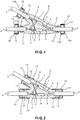
- Fig. 1 the arrangement according to the invention is shown according to a first embodiment in a longitudinal section.
- existing housing 1 are three electrical lines 2, 3, 4 led into it.
- the electrical lines 2, 3, 4 have a jacket made of insulating material, for example made of silicone.
- the housing 1 is an insulating body 1, which consists for example of polyamide (PA) or polyurethane (PUR).
- PA polyamide
- PUR polyurethane
- the line 2 is connected, for example, to a voltage source arranged in a motor vehicle or to an electronic control unit connected thereto, and the lines 3 and 4 can lead to consumers or electrical appliances located in the motor vehicle.
- the conductors of the lines 2, 3, 4 are connected to one another at a connection point V.
- the connection point V is completely enclosed by the insulating body 1.
- the lines 2, 3, 4 each have two wires 5, 6 consisting of insulated electrical conductors.
- the conductors of the wires 5, 6 are electrically conductively connected to one another at the connection point V by
- the insulating body 1 has three outwardly facing, tubular projections 9, 10, 11 or nozzle, through which the lines 2, 3, 4 are inserted into the same.
- the projections 9, 10, 11 have for passages through which the lines 2, 3, 4 are passed.
- the arrangement further comprises for each of the lines 2, 3, 4, an annular sealing element 12, which rests tightly against the jacket of the respective line 2, 3, 4.
- the sealing elements 12 may for example consist of silicone or of ethylene-propylene-diene rubber (EPDM). These materials are suitable for firmly adhering to the cable sheaths made of silicone or on lines with networked insulation and media-tight.
- the sealing elements 12 are arranged outside of the insulating body 1. On each of the sealing elements 12, a protective element 13 is fixed, which completely surrounds the respective sealing element 12.
- the protective elements consist for example of PA or PUR.
- the protective elements 13 each have two parts 13a, 13b.
- the first part 13a has a tubular extension or connecting piece, which rests against the insulation of the respective line 2, 3, 4 and is enclosed by the respective projection 9, 10, 11 of the insulating body 1 in a material-tight and media-tight manner.
- the Sealing ring 12 is arranged within the first part 13 a of the protective element 13 .
- the second part 13b is executed in the example shown as a cap. It is fixed all around on the first part 13 a, so that the sealing element 12 is surrounded by the two parts 13 a, 13 b of the protective element 13 all around tight.
- the two parts 13a, 13b are positively connected with each other, for example, locked or pressed.
- the sealing elements 12 are thus each media-tight, by means of the protective elements 13, connected to the projections 9, 10, 11 of the insulating body 1.
- the unit of sealing element 12 and protective element 13 can be regarded as a closure element, with which in each case a passage of a line 2, 3, 4 is closed and sealed in the insulating body 1.
- the projections 9, 10, 11 of the insulating body 1 inner grooves and the lugs of the closure elements may have external grooves, which are respectively engaged with each other. As a result, the cohesive and media-tight connection between the two connecting pieces is increased in each case.
- Fig. 2 the arrangement according to the invention is shown according to a second embodiment in a longitudinal section.
- the insulating body 1 also has three outwardly facing, tubular projections 9, 10, 11, through which the lines 2, 3, 4 are inserted into the insulating body.
- the closure elements in this example also each consist of a sealing element 12 and a protective element 13.
- the sealing elements 12 and the surrounding protective elements 13 each have a cap-like shape, which is open to the insulating body 1 out.
- the sealing elements 12 are each applied to the projections 9, 10, 11 of the insulating body 1, so that the sealing elements 12 at the same time bear against the projections 9, 10, 11 and to the insulation of the lines 2, 3, 4 non-positively and media-tight.
- the sealing elements 12 may for example consist of silicone or EPDM.
- the protective elements 13 are mounted on the sealing elements 12 and surround both the sealing elements 12 and the projections 9, 10, 11 adjacent region of the insulating body 1.
- the protective elements 13 secure the sealing elements 12 in addition, so that they are not in the assembled state on the lines 2, 3, 4 undesirably be moved.
- the protective elements 13 can be fixed, for example, to the insulating body 1 by means of a latching mechanism 14.
- the projections 9, 10, 11 have external grooves 15 which engage in the elastic material of the sealing elements 12 and thus ensure a secure fit thereof.
- Fig. 1 The arrangement according to the invention, as in Fig. 1 is mounted, for example, as follows.
- the joint V is established.
- the projections 9, 10, 11 of the insulating body 1 are formed around the projections of the protective elements 13.
- the sealing elements 12 are moved on the line so that they are enclosed by the first parts 13 a. Subsequently, in each case the first parts 13a of the protective elements 13 are closed with the second parts 13b.
- the arrangement according to the invention as shown in FIG Fig. 2 is prepared as follows.
- the protective elements 13 and the sealing elements 12 are each pushed onto the three lines 2, 3, 4 to be connected.
- the elements 12, 13 are made of the connection point V to be produced seen a little further than being pushed to their final position on the lines.
- the joint V is established.
- the projections 9, 10, 11 are made so that they each extend beyond the sheaths of the lines 2, 3, 4 and tightly against them.
- the sealing elements 12 and then the protective elements are moved to their final position. This is done so that the sealing elements 12 each tight against the projections 9, 10, 11 and the protective elements 13 tightly surround the sealing elements 12 and non-positively or positively fixed on the insulating body 1.
- the protective elements 13 are fixed by means of a latching mechanism 14 at the ends of the insulating body 1.
- connection point V is surrounded all around tightly with insulating material. As a result, an additional seal against moisture and a high resistance of the arrangement against shock and vibration loads of the arrangement can be achieved.
Landscapes
- Connector Housings Or Holding Contact Members (AREA)
- Insulating Bodies (AREA)
Priority Applications (2)
| Application Number | Priority Date | Filing Date | Title |
|---|---|---|---|
| EP16306804.2A EP3340392B1 (fr) | 2016-12-23 | 2016-12-23 | Système de branchement de conduites électriques |
| ES16306804T ES2738603T3 (es) | 2016-12-23 | 2016-12-23 | Disposición para conectar líneas eléctricas |
Applications Claiming Priority (1)
| Application Number | Priority Date | Filing Date | Title |
|---|---|---|---|
| EP16306804.2A EP3340392B1 (fr) | 2016-12-23 | 2016-12-23 | Système de branchement de conduites électriques |
Publications (2)
| Publication Number | Publication Date |
|---|---|
| EP3340392A1 true EP3340392A1 (fr) | 2018-06-27 |
| EP3340392B1 EP3340392B1 (fr) | 2019-05-15 |
Family
ID=57749795
Family Applications (1)
| Application Number | Title | Priority Date | Filing Date |
|---|---|---|---|
| EP16306804.2A Active EP3340392B1 (fr) | 2016-12-23 | 2016-12-23 | Système de branchement de conduites électriques |
Country Status (2)
| Country | Link |
|---|---|
| EP (1) | EP3340392B1 (fr) |
| ES (1) | ES2738603T3 (fr) |
Cited By (3)
| Publication number | Priority date | Publication date | Assignee | Title |
|---|---|---|---|---|
| CN112423528A (zh) * | 2019-08-21 | 2021-02-26 | 大众汽车股份公司 | 用于连接和密封电气的部件的方法 |
| WO2022223393A1 (fr) * | 2021-04-23 | 2022-10-27 | Belden Deutschland Gmbh | Dispositifs d'entrée/sortie à lignes moulées par injection |
| DE102018217580B4 (de) | 2018-10-15 | 2023-07-06 | Continental Automotive Technologies GmbH | Kabelanordnung zum Anschluss eines Raddrehzahlsensors und einer elektrischen Parkbremse |
Citations (5)
| Publication number | Priority date | Publication date | Assignee | Title |
|---|---|---|---|---|
| DE19741572A1 (de) * | 1997-09-20 | 1999-03-25 | Dieter Hemstedt | Vorrichtung zum Verbinden isolierter elektrischer Leiter |
| EP2485336A1 (fr) * | 2011-02-02 | 2012-08-08 | Nexans | Elément de couplage pour conduites |
| EP2605337A1 (fr) * | 2010-08-09 | 2013-06-19 | Yazaki Corporation | Structure étanche pour chemin de conduction |
| DE102013011874A1 (de) * | 2013-07-17 | 2015-01-22 | Leoni Bordnetz-Systeme Gmbh | Elektrischer Leistungsverteiler für ein Elektro- oder Hybridfahrzeug sowie Verteilergehäuse für einen derartigen Leistungsverteiler |
| DE102014212375A1 (de) * | 2014-06-26 | 2015-12-31 | Leoni Bordnetz-Systeme Gmbh | Verfahren zur Herstellung einer abgedichteten Leitungsdurchführung sowie abgedichtete Leitungsdurchführung |
Family Cites Families (1)
| Publication number | Priority date | Publication date | Assignee | Title |
|---|---|---|---|---|
| GB1280041A (en) * | 1969-07-28 | 1972-07-05 | Sumitomo Electric Industries | Cable joint |
-
2016
- 2016-12-23 ES ES16306804T patent/ES2738603T3/es active Active
- 2016-12-23 EP EP16306804.2A patent/EP3340392B1/fr active Active
Patent Citations (6)
| Publication number | Priority date | Publication date | Assignee | Title |
|---|---|---|---|---|
| DE19741572A1 (de) * | 1997-09-20 | 1999-03-25 | Dieter Hemstedt | Vorrichtung zum Verbinden isolierter elektrischer Leiter |
| EP2605337A1 (fr) * | 2010-08-09 | 2013-06-19 | Yazaki Corporation | Structure étanche pour chemin de conduction |
| EP2485336A1 (fr) * | 2011-02-02 | 2012-08-08 | Nexans | Elément de couplage pour conduites |
| EP2485337B1 (fr) | 2011-02-02 | 2015-03-04 | Nexans | Elément de couplage pour conduites |
| DE102013011874A1 (de) * | 2013-07-17 | 2015-01-22 | Leoni Bordnetz-Systeme Gmbh | Elektrischer Leistungsverteiler für ein Elektro- oder Hybridfahrzeug sowie Verteilergehäuse für einen derartigen Leistungsverteiler |
| DE102014212375A1 (de) * | 2014-06-26 | 2015-12-31 | Leoni Bordnetz-Systeme Gmbh | Verfahren zur Herstellung einer abgedichteten Leitungsdurchführung sowie abgedichtete Leitungsdurchführung |
Cited By (7)
| Publication number | Priority date | Publication date | Assignee | Title |
|---|---|---|---|---|
| DE102018217580B4 (de) | 2018-10-15 | 2023-07-06 | Continental Automotive Technologies GmbH | Kabelanordnung zum Anschluss eines Raddrehzahlsensors und einer elektrischen Parkbremse |
| CN112423528A (zh) * | 2019-08-21 | 2021-02-26 | 大众汽车股份公司 | 用于连接和密封电气的部件的方法 |
| KR20210023707A (ko) * | 2019-08-21 | 2021-03-04 | 폭스바겐 악티엔게젤샤프트 | 전기 부품들을 연결하고 밀봉하기 위한 방법 |
| CN112423528B (zh) * | 2019-08-21 | 2022-09-13 | 大众汽车股份公司 | 用于连接和密封电气的部件的方法 |
| DE102019212461B4 (de) | 2019-08-21 | 2025-01-23 | Volkswagen Aktiengesellschaft | Verfahren zum Verbinden und Abdichten von elektrischen Komponenten |
| WO2022223393A1 (fr) * | 2021-04-23 | 2022-10-27 | Belden Deutschland Gmbh | Dispositifs d'entrée/sortie à lignes moulées par injection |
| JP2024521985A (ja) * | 2021-04-23 | 2024-06-05 | ベルデン ドイチュランド ゲゼルシャフト ミット ベシュレンクテル ハフツング | 射出成形により取り付けられたラインを備える入出力機器 |
Also Published As
| Publication number | Publication date |
|---|---|
| EP3340392B1 (fr) | 2019-05-15 |
| ES2738603T3 (es) | 2020-01-24 |
Similar Documents
| Publication | Publication Date | Title |
|---|---|---|
| EP3745541B1 (fr) | Prise enfichable pour un raccordement combiné électrique et liaison de données | |
| EP2777096B2 (fr) | Unité de connexion à fiches multipolaire pour systèmes électriques triphasés | |
| DE112008003276T5 (de) | Verfahren zum Ausbilden eines wasserdichten Verbindungsabscchnitts und Kabelbaum, welcher mit einem wasserdichten, durch das Verfahren ausgebildeten Verbindungsabschnitt versehen ist | |
| DE1465493A1 (de) | Elektrisches Verbindungselement | |
| DE102017105682A1 (de) | Kontaktträger, elektrische Kontakteinrichtung sowie Verfahren zum Herstellen eines konfektionierten Kabels | |
| DE112014001079T5 (de) | Kabelstrang | |
| DE10331416B4 (de) | Abgedichtetes elektrisches Verbindungssystem | |
| EP2850700B1 (fr) | Boîtier de connecteur enfichable et connecteur enfichable | |
| EP0893857A2 (fr) | Systeme de connexion pour conducteur de chauffage dans un avion | |
| EP3340392B1 (fr) | Système de branchement de conduites électriques | |
| DE102018127900A1 (de) | Kabelschuh, Kontaktelement und Verfahren zu dessen Herstellung | |
| WO2021078423A1 (fr) | Boîtier, plus particulièrement boîtier de ligne, système, et procédé de production d'un système de ce type | |
| EP2192655B1 (fr) | Connecteur étanche pour câbles à haute tension dans l'industrie automobile | |
| WO2009103456A1 (fr) | Élément connecteur à fiche, à effet d'étanchéité dans la région de raccordement du câble | |
| EP3477777B1 (fr) | Ligne électrique pourvue d'un terminal de blindage | |
| EP2099099B1 (fr) | Elément de connexion électrique doté d'un câble électrique connecté | |
| DE3002320A1 (de) | Geraete-anschlusstecker und verfahren zu dessen herstellung | |
| DE102018216965B3 (de) | Verfahren zum Kontaktieren zweier elektrischer Leitungen sowie Steckervorrichtung | |
| DE102008031085A1 (de) | Kupplungsteil für eine elektrische Leitung | |
| EP1870909A1 (fr) | Câble plat | |
| WO2014040668A1 (fr) | Couvercle d'un carter de transmission | |
| AT517416B1 (de) | Kabel und verfahren zur herstellung eines kabels | |
| EP0285079A2 (fr) | Dispositif de serrage pour la réalisation d'une dérivation sur les conducteurs d'un câble de tension et réalisation d'une telle dérivation | |
| EP1095430A1 (fr) | Procede de protection de torons de cables | |
| EP3145040B1 (fr) | Câbles comprenant un point de connexion |
Legal Events
| Date | Code | Title | Description |
|---|---|---|---|
| PUAI | Public reference made under article 153(3) epc to a published international application that has entered the european phase |
Free format text: ORIGINAL CODE: 0009012 |
|
| STAA | Information on the status of an ep patent application or granted ep patent |
Free format text: STATUS: REQUEST FOR EXAMINATION WAS MADE |
|
| 17P | Request for examination filed |
Effective date: 20170908 |
|
| AK | Designated contracting states |
Kind code of ref document: A1 Designated state(s): AL AT BE BG CH CY CZ DE DK EE ES FI FR GB GR HR HU IE IS IT LI LT LU LV MC MK MT NL NO PL PT RO RS SE SI SK SM TR |
|
| AX | Request for extension of the european patent |
Extension state: BA ME |
|
| GRAP | Despatch of communication of intention to grant a patent |
Free format text: ORIGINAL CODE: EPIDOSNIGR1 |
|
| STAA | Information on the status of an ep patent application or granted ep patent |
Free format text: STATUS: GRANT OF PATENT IS INTENDED |
|
| INTG | Intention to grant announced |
Effective date: 20181219 |
|
| GRAS | Grant fee paid |
Free format text: ORIGINAL CODE: EPIDOSNIGR3 |
|
| GRAA | (expected) grant |
Free format text: ORIGINAL CODE: 0009210 |
|
| STAA | Information on the status of an ep patent application or granted ep patent |
Free format text: STATUS: THE PATENT HAS BEEN GRANTED |
|
| AK | Designated contracting states |
Kind code of ref document: B1 Designated state(s): AL AT BE BG CH CY CZ DE DK EE ES FI FR GB GR HR HU IE IS IT LI LT LU LV MC MK MT NL NO PL PT RO RS SE SI SK SM TR |
|
| REG | Reference to a national code |
Ref country code: CH Ref legal event code: EP |
|
| REG | Reference to a national code |
Ref country code: DE Ref legal event code: R096 Ref document number: 502016004691 Country of ref document: DE |
|
| REG | Reference to a national code |
Ref country code: IE Ref legal event code: FG4D Free format text: LANGUAGE OF EP DOCUMENT: GERMAN |
|
| REG | Reference to a national code |
Ref country code: NL Ref legal event code: MP Effective date: 20190515 |
|
| REG | Reference to a national code |
Ref country code: LT Ref legal event code: MG4D |
|
| PG25 | Lapsed in a contracting state [announced via postgrant information from national office to epo] |
Ref country code: AL Free format text: LAPSE BECAUSE OF FAILURE TO SUBMIT A TRANSLATION OF THE DESCRIPTION OR TO PAY THE FEE WITHIN THE PRESCRIBED TIME-LIMIT Effective date: 20190515 Ref country code: PT Free format text: LAPSE BECAUSE OF FAILURE TO SUBMIT A TRANSLATION OF THE DESCRIPTION OR TO PAY THE FEE WITHIN THE PRESCRIBED TIME-LIMIT Effective date: 20190915 Ref country code: NO Free format text: LAPSE BECAUSE OF FAILURE TO SUBMIT A TRANSLATION OF THE DESCRIPTION OR TO PAY THE FEE WITHIN THE PRESCRIBED TIME-LIMIT Effective date: 20190815 Ref country code: HR Free format text: LAPSE BECAUSE OF FAILURE TO SUBMIT A TRANSLATION OF THE DESCRIPTION OR TO PAY THE FEE WITHIN THE PRESCRIBED TIME-LIMIT Effective date: 20190515 Ref country code: SE Free format text: LAPSE BECAUSE OF FAILURE TO SUBMIT A TRANSLATION OF THE DESCRIPTION OR TO PAY THE FEE WITHIN THE PRESCRIBED TIME-LIMIT Effective date: 20190515 Ref country code: LT Free format text: LAPSE BECAUSE OF FAILURE TO SUBMIT A TRANSLATION OF THE DESCRIPTION OR TO PAY THE FEE WITHIN THE PRESCRIBED TIME-LIMIT Effective date: 20190515 Ref country code: NL Free format text: LAPSE BECAUSE OF FAILURE TO SUBMIT A TRANSLATION OF THE DESCRIPTION OR TO PAY THE FEE WITHIN THE PRESCRIBED TIME-LIMIT Effective date: 20190515 Ref country code: FI Free format text: LAPSE BECAUSE OF FAILURE TO SUBMIT A TRANSLATION OF THE DESCRIPTION OR TO PAY THE FEE WITHIN THE PRESCRIBED TIME-LIMIT Effective date: 20190515 |
|
| PG25 | Lapsed in a contracting state [announced via postgrant information from national office to epo] |
Ref country code: LV Free format text: LAPSE BECAUSE OF FAILURE TO SUBMIT A TRANSLATION OF THE DESCRIPTION OR TO PAY THE FEE WITHIN THE PRESCRIBED TIME-LIMIT Effective date: 20190515 Ref country code: RS Free format text: LAPSE BECAUSE OF FAILURE TO SUBMIT A TRANSLATION OF THE DESCRIPTION OR TO PAY THE FEE WITHIN THE PRESCRIBED TIME-LIMIT Effective date: 20190515 Ref country code: BG Free format text: LAPSE BECAUSE OF FAILURE TO SUBMIT A TRANSLATION OF THE DESCRIPTION OR TO PAY THE FEE WITHIN THE PRESCRIBED TIME-LIMIT Effective date: 20190815 Ref country code: GR Free format text: LAPSE BECAUSE OF FAILURE TO SUBMIT A TRANSLATION OF THE DESCRIPTION OR TO PAY THE FEE WITHIN THE PRESCRIBED TIME-LIMIT Effective date: 20190816 |
|
| REG | Reference to a national code |
Ref country code: ES Ref legal event code: FG2A Ref document number: 2738603 Country of ref document: ES Kind code of ref document: T3 Effective date: 20200124 |
|
| PG25 | Lapsed in a contracting state [announced via postgrant information from national office to epo] |
Ref country code: SK Free format text: LAPSE BECAUSE OF FAILURE TO SUBMIT A TRANSLATION OF THE DESCRIPTION OR TO PAY THE FEE WITHIN THE PRESCRIBED TIME-LIMIT Effective date: 20190515 Ref country code: EE Free format text: LAPSE BECAUSE OF FAILURE TO SUBMIT A TRANSLATION OF THE DESCRIPTION OR TO PAY THE FEE WITHIN THE PRESCRIBED TIME-LIMIT Effective date: 20190515 Ref country code: DK Free format text: LAPSE BECAUSE OF FAILURE TO SUBMIT A TRANSLATION OF THE DESCRIPTION OR TO PAY THE FEE WITHIN THE PRESCRIBED TIME-LIMIT Effective date: 20190515 Ref country code: CZ Free format text: LAPSE BECAUSE OF FAILURE TO SUBMIT A TRANSLATION OF THE DESCRIPTION OR TO PAY THE FEE WITHIN THE PRESCRIBED TIME-LIMIT Effective date: 20190515 |
|
| REG | Reference to a national code |
Ref country code: DE Ref legal event code: R097 Ref document number: 502016004691 Country of ref document: DE |
|
| PG25 | Lapsed in a contracting state [announced via postgrant information from national office to epo] |
Ref country code: SM Free format text: LAPSE BECAUSE OF FAILURE TO SUBMIT A TRANSLATION OF THE DESCRIPTION OR TO PAY THE FEE WITHIN THE PRESCRIBED TIME-LIMIT Effective date: 20190515 |
|
| PLBE | No opposition filed within time limit |
Free format text: ORIGINAL CODE: 0009261 |
|
| STAA | Information on the status of an ep patent application or granted ep patent |
Free format text: STATUS: NO OPPOSITION FILED WITHIN TIME LIMIT |
|
| PG25 | Lapsed in a contracting state [announced via postgrant information from national office to epo] |
Ref country code: TR Free format text: LAPSE BECAUSE OF FAILURE TO SUBMIT A TRANSLATION OF THE DESCRIPTION OR TO PAY THE FEE WITHIN THE PRESCRIBED TIME-LIMIT Effective date: 20190515 |
|
| 26N | No opposition filed |
Effective date: 20200218 |
|
| PG25 | Lapsed in a contracting state [announced via postgrant information from national office to epo] |
Ref country code: PL Free format text: LAPSE BECAUSE OF FAILURE TO SUBMIT A TRANSLATION OF THE DESCRIPTION OR TO PAY THE FEE WITHIN THE PRESCRIBED TIME-LIMIT Effective date: 20190515 |
|
| PG25 | Lapsed in a contracting state [announced via postgrant information from national office to epo] |
Ref country code: SI Free format text: LAPSE BECAUSE OF FAILURE TO SUBMIT A TRANSLATION OF THE DESCRIPTION OR TO PAY THE FEE WITHIN THE PRESCRIBED TIME-LIMIT Effective date: 20190515 |
|
| REG | Reference to a national code |
Ref country code: CH Ref legal event code: PL |
|
| REG | Reference to a national code |
Ref country code: BE Ref legal event code: MM Effective date: 20191231 |
|
| PG25 | Lapsed in a contracting state [announced via postgrant information from national office to epo] |
Ref country code: MC Free format text: LAPSE BECAUSE OF FAILURE TO SUBMIT A TRANSLATION OF THE DESCRIPTION OR TO PAY THE FEE WITHIN THE PRESCRIBED TIME-LIMIT Effective date: 20190515 |
|
| PG25 | Lapsed in a contracting state [announced via postgrant information from national office to epo] |
Ref country code: LU Free format text: LAPSE BECAUSE OF NON-PAYMENT OF DUE FEES Effective date: 20191223 Ref country code: IE Free format text: LAPSE BECAUSE OF NON-PAYMENT OF DUE FEES Effective date: 20191223 |
|
| PG25 | Lapsed in a contracting state [announced via postgrant information from national office to epo] |
Ref country code: CH Free format text: LAPSE BECAUSE OF NON-PAYMENT OF DUE FEES Effective date: 20191231 Ref country code: LI Free format text: LAPSE BECAUSE OF NON-PAYMENT OF DUE FEES Effective date: 20191231 Ref country code: BE Free format text: LAPSE BECAUSE OF NON-PAYMENT OF DUE FEES Effective date: 20191231 |
|
| PG25 | Lapsed in a contracting state [announced via postgrant information from national office to epo] |
Ref country code: RO Free format text: LAPSE BECAUSE OF FAILURE TO SUBMIT A TRANSLATION OF THE DESCRIPTION OR TO PAY THE FEE WITHIN THE PRESCRIBED TIME-LIMIT Effective date: 20190515 |
|
| PG25 | Lapsed in a contracting state [announced via postgrant information from national office to epo] |
Ref country code: CY Free format text: LAPSE BECAUSE OF FAILURE TO SUBMIT A TRANSLATION OF THE DESCRIPTION OR TO PAY THE FEE WITHIN THE PRESCRIBED TIME-LIMIT Effective date: 20190515 |
|
| PG25 | Lapsed in a contracting state [announced via postgrant information from national office to epo] |
Ref country code: IS Free format text: LAPSE BECAUSE OF FAILURE TO SUBMIT A TRANSLATION OF THE DESCRIPTION OR TO PAY THE FEE WITHIN THE PRESCRIBED TIME-LIMIT Effective date: 20190915 |
|
| PG25 | Lapsed in a contracting state [announced via postgrant information from national office to epo] |
Ref country code: MT Free format text: LAPSE BECAUSE OF FAILURE TO SUBMIT A TRANSLATION OF THE DESCRIPTION OR TO PAY THE FEE WITHIN THE PRESCRIBED TIME-LIMIT Effective date: 20190515 Ref country code: HU Free format text: LAPSE BECAUSE OF FAILURE TO SUBMIT A TRANSLATION OF THE DESCRIPTION OR TO PAY THE FEE WITHIN THE PRESCRIBED TIME-LIMIT; INVALID AB INITIO Effective date: 20161223 |
|
| GBPC | Gb: european patent ceased through non-payment of renewal fee |
Effective date: 20201223 |
|
| PG25 | Lapsed in a contracting state [announced via postgrant information from national office to epo] |
Ref country code: GB Free format text: LAPSE BECAUSE OF NON-PAYMENT OF DUE FEES Effective date: 20201223 |
|
| PG25 | Lapsed in a contracting state [announced via postgrant information from national office to epo] |
Ref country code: MK Free format text: LAPSE BECAUSE OF FAILURE TO SUBMIT A TRANSLATION OF THE DESCRIPTION OR TO PAY THE FEE WITHIN THE PRESCRIBED TIME-LIMIT Effective date: 20190515 |
|
| REG | Reference to a national code |
Ref country code: AT Ref legal event code: MM01 Ref document number: 1134524 Country of ref document: AT Kind code of ref document: T Effective date: 20211223 |
|
| PG25 | Lapsed in a contracting state [announced via postgrant information from national office to epo] |
Ref country code: AT Free format text: LAPSE BECAUSE OF NON-PAYMENT OF DUE FEES Effective date: 20211223 |
|
| PGFP | Annual fee paid to national office [announced via postgrant information from national office to epo] |
Ref country code: DE Payment date: 20251211 Year of fee payment: 10 |
|
| PGFP | Annual fee paid to national office [announced via postgrant information from national office to epo] |
Ref country code: IT Payment date: 20251223 Year of fee payment: 10 |
|
| PGFP | Annual fee paid to national office [announced via postgrant information from national office to epo] |
Ref country code: FR Payment date: 20251229 Year of fee payment: 10 |
|
| PGFP | Annual fee paid to national office [announced via postgrant information from national office to epo] |
Ref country code: ES Payment date: 20260130 Year of fee payment: 10 |