EP3340739A1 - Porte de four à micro-ondes - Google Patents
Porte de four à micro-ondes Download PDFInfo
- Publication number
- EP3340739A1 EP3340739A1 EP16205547.9A EP16205547A EP3340739A1 EP 3340739 A1 EP3340739 A1 EP 3340739A1 EP 16205547 A EP16205547 A EP 16205547A EP 3340739 A1 EP3340739 A1 EP 3340739A1
- Authority
- EP
- European Patent Office
- Prior art keywords
- oven
- door
- glass panel
- door cover
- cover
- Prior art date
- Legal status (The legal status is an assumption and is not a legal conclusion. Google has not performed a legal analysis and makes no representation as to the accuracy of the status listed.)
- Granted
Links
- 239000011521 glass Substances 0.000 claims abstract description 124
- 238000010411 cooking Methods 0.000 claims abstract description 11
- 238000010438 heat treatment Methods 0.000 claims abstract description 11
- 239000003989 dielectric material Substances 0.000 claims description 10
- 229920000642 polymer Polymers 0.000 claims description 10
- 229910052751 metal Inorganic materials 0.000 claims description 8
- 239000002184 metal Substances 0.000 claims description 8
- 239000003292 glue Substances 0.000 description 9
- 229920001296 polysiloxane Polymers 0.000 description 5
- 230000005672 electromagnetic field Effects 0.000 description 3
- 238000012986 modification Methods 0.000 description 2
- 230000004048 modification Effects 0.000 description 2
- 229920003023 plastic Polymers 0.000 description 2
- 239000004033 plastic Substances 0.000 description 2
- 239000004411 aluminium Substances 0.000 description 1
- 229910052782 aluminium Inorganic materials 0.000 description 1
- XAGFODPZIPBFFR-UHFFFAOYSA-N aluminium Chemical compound [Al] XAGFODPZIPBFFR-UHFFFAOYSA-N 0.000 description 1
- 235000013361 beverage Nutrition 0.000 description 1
- 230000000903 blocking effect Effects 0.000 description 1
- 238000001465 metallisation Methods 0.000 description 1
- 238000000034 method Methods 0.000 description 1
- 229910001220 stainless steel Inorganic materials 0.000 description 1
- 239000010935 stainless steel Substances 0.000 description 1
Images


Classifications
-
- H—ELECTRICITY
- H05—ELECTRIC TECHNIQUES NOT OTHERWISE PROVIDED FOR
- H05B—ELECTRIC HEATING; ELECTRIC LIGHT SOURCES NOT OTHERWISE PROVIDED FOR; CIRCUIT ARRANGEMENTS FOR ELECTRIC LIGHT SOURCES, IN GENERAL
- H05B6/00—Heating by electric, magnetic or electromagnetic fields
- H05B6/64—Heating using microwaves
- H05B6/6414—Aspects relating to the door of the microwave heating apparatus
-
- H—ELECTRICITY
- H05—ELECTRIC TECHNIQUES NOT OTHERWISE PROVIDED FOR
- H05B—ELECTRIC HEATING; ELECTRIC LIGHT SOURCES NOT OTHERWISE PROVIDED FOR; CIRCUIT ARRANGEMENTS FOR ELECTRIC LIGHT SOURCES, IN GENERAL
- H05B6/00—Heating by electric, magnetic or electromagnetic fields
- H05B6/64—Heating using microwaves
- H05B6/76—Prevention of microwave leakage, e.g. door sealings
- H05B6/763—Microwave radiation seals for doors
Definitions
- the present invention relates to an oven door for a microwave oven or a cooking oven with microwave heating functions. Further, the present invention relates to a microwave oven or a cooking oven with microwave heating functions.
- a microwave oven generates electromagnetic fields for heating food and beverages in the oven cavity.
- the oven door of the microwave oven comprises at least an inner glass panel and an outer glass panel.
- the oven door of the microwave oven is partially transparent, so that the user is able to monitor the progress of the cooking process in the oven cavity.
- the transparent area of the oven door for the microwave oven is relative small, since a wave choke device is arranged within the door frame. Said wave choke device blocks the gap between the oven door and a front frame of the microwave oven against the electromagnetic field inside the oven cavity.
- the wave choke device is covered by a door cover made of non-metallic parts.
- said door cover is made of high temperature resistant polymers.
- the inner glass panel and the door frame are connected by a glue joint consisting of silicone.
- the temperature resistance of silicone is lower than 200°C, while the temperature resistance of the door frame and glass panel is higher.
- the glue joint is positioned in an area of critical temperatures, due to the extension of the wave choke device. Thus, the glue joint is thermally stressed, so that failures in the oven door may occur. For example, condensate may infiltrate into the interior of the oven door. Further, the inner glass panel may be lost.
- FIG 6 illustrates a schematic sectional perspective view of the inner part 10 of the oven door for the microwave oven according to the prior art.
- the inner part 10 of the oven door includes a door cover 12 and an inner glass panel 14.
- the door cover 12 encloses the inner glass panel 14.
- the inner glass panel 14 faces the oven cavity of the microwave oven in the closed state of the oven door, wherein a gasket is arranged between the inner glass panel 14 and the oven cavity.
- the welded system consisting of glass panel 14 and door cover 12 includes an L-shaped cross-section, wherein an inner leg of said L-shaped cross-section extends parallel to the plane of the inner glass panel 14.
- An outer leg of the L-shaped cross-section encloses the inner leg, is arranged perpendicular to said inner leg and extends outwards from the inner leg.
- the inner leg of the door cover 12 and an outer portion of an inner surface of the inner glass panel 14 overlap.
- said door cover 12 and inner glass panel 14 are glued together.
- a glue joint 18 is formed in the overlap area of the inner leg of the door cover 12 and the inner glass panel 14.
- the outer portion of the inner surface of the inner glass panel 14 is connected to an outer side of the inner leg of the door cover 12 by the glue joint 18.
- the object is achieved by the door for the microwave oven according to claim 1.
- an oven door for a microwave oven or a cooking oven with microwave heating functions is provided, wherein:
- the core of the present invention is the welded joint between the door cover and the glass panel.
- the welded joint provides a high temperature resistance and a tight connection between the door cover and the inner glass panel. Further, the welded joint provides an improved design of the inner side of the oven door.
- the welded joint forms a closed elongated path or at least one open elongated path, wherein preferably the door cover encloses completely the glass panel.
- the door cover enclosing completely the glass panel contributes to the tight connection between the door cover and the inner glass panel.
- the glass panel may be an inner glass panel and faces an oven cavity in a closed state of the oven door, wherein preferably a gasket is provided between said inner glass panel and oven cavity.
- the inner glass panel is in a high temperature area.
- the door cover may include at least one dielectric material, wherein preferably at least a part of the door cover is made of polymers, or the door cover is made of metal.
- the overlap area is formed by an outer portion of a surface of the glass panel and a surface at an inner portion of the door cover, wherein the surface at the inner portion of the door cover extends parallel to the plane of the glass panel, and wherein preferably the inner portion of the door cover faces the oven cavity in the closed state of the oven door, while the welded joint at the inner portion of the door cover faces away from the oven cavity in the closed state of the oven door.
- the door cover may include an L-shaped cross-section, wherein a first leg of the L-shaped cross-section may form the inner portion of the cross-section of the door cover, while a second leg of the L-shaped cross-section may enclose the first leg and may extend away from the oven cavity in the closed state of the oven door.
- the first leg of the L-shaped cross-section of the door cover is made of the dielectric material, while the second leg of the L-shaped cross-section of said door cover is made of metal.
- the first leg of the L-shaped cross-section of the door cover is made of polymers.
- the corner of the L-shaped cross-section of the door cover is made of the dielectric material, preferably of polymers.
- the overlap area is formed by an inner side of the door cover and a circumferential side of the inner glass panel, so that the circumferential side of the inner glass panel is connected to the inner side of the door cover by the welded joint.
- the oven door may comprise an outer glass panel attached or attachable to an outer side of the door cover, wherein said outer side of the door cover faces away from the oven cavity.
- the outer glass panel is glued to door columns, wherein preferably the door cover is fixed to said door columns.
- the oven door may comprise a further door cover glued to the outer glass panel, wherein preferably the door cover is fixed to said further door cover.
- the oven door may comprise at least one intermediate glass panel arranged between the inner glass panel and the outer glass panel.
- the oven door comprises a wave choke device enclosing at least one glass panel and covered by the door cover and/or the further door cover.
- the wave choke device is provided for blocking a gap formed between the oven door and the microwave oven against the electromagnetic field inside the oven cavity.
- the present invention relates to a microwave oven or a cooking oven with microwave heating functions, wherein the microwave oven or cooking oven with microwave heating functions, respectively, comprises at least one oven door mentioned above.
- FIG 1 illustrates a schematic view at an outer side of an inner part 10 of the oven door for a microwave oven according to a first embodiment of the present invention.
- the outer side of the inner part 10 of the oven door faces away from an oven cavity in a closed state of said door.
- the inner part 10 of the oven door is that part facing an oven cavity of the microwave oven in a closed state of the oven door.
- the term “inner” relates to the direction to the oven cavity of the microwave oven in a closed state of the oven door.
- the term “outer” relates to the direction away from the oven cavity of the microwave oven and to the front of said microwave oven in the closed state of the oven door.
- the inner part 10 of the oven door includes a door cover 12 and an inner glass panel 14.
- the door cover 12 encloses the inner glass panel 14.
- the inner glass panel 14 faces the oven cavity of the microwave oven in the closed state of the oven door, wherein a gasket is provided between the inner glass panel 14 and the oven cavity.
- the gasket touches the inner glass panel 14 in the closed state of the oven door.
- the gasket is made of silicone or mesh. Mesh is suitable for pyrolytic ovens.
- the door cover 12 has an L-shaped cross-section.
- An inner leg of said L-shaped cross-section extends parallel to the plane of the inner glass panel 14.
- An outer leg of the L-shaped cross-section encloses the inner leg, is arranged perpendicular to said inner leg and extends outwards from the inner leg.
- the inner leg of the door cover 12 and an outer portion of an inner surface of the inner glass panel 14 overlap.
- said door cover 12 and inner glass panel 14 are welded together.
- the door cover 12 is made of plastics.
- the door cover 12 is made of polymers.
- FIG 2 illustrates a schematic front view of the inner part 10 of the oven door for the microwave oven according to the first embodiment of the present invention.
- the inner side of the inner part 10 of the oven door faces the oven cavity in the closed state of said door.
- FIG 2 clarifies the connection between the door cover 12 and the inner glass panel 14.
- a welded joint 16 is formed in the overlap area between the inner leg of the door cover 12 and the inner glass panel 14.
- the door cover 12 and the inner glass panel 14 are welded together.
- the welded joint 16 provides a high temperature resistance. Further, the welded joint 16 provides a tight connection between the door cover 12 and the inner glass panel 14. Moreover, the welded joint 16 provides an improved design of the inner part 10 of the oven door.
- FIG 3 illustrates a schematic sectional perspective view of the inner part 10 of the oven door for the microwave oven according to the first embodiment of the present invention.
- FIG 3 clarifies the arrangement of the welded joint 16 between the door cover 12 and the inner glass panel 14.
- the welded joint 16 is formed in the overlap area of the inner leg of the door cover 12 and the inner glass panel 14.
- the outer portion of the inner surface of the inner glass panel 14 is connected to an outer side of the inner leg of the door cover 12 by the welded joint 16.
- the welded joint 16 allows the high temperature resistance and the tight connection between the door cover 12 and the inner glass panel 14.
- the welded joint 16 provides an improved design of the inner part 10 of the oven door.
- the door cover 12 has the L-shaped cross-section.
- the inner leg of said L-shaped cross-section extends parallel to the plane of the inner glass panel 14, while the outer leg of the L-shaped cross-section encloses the inner leg.
- the outer leg is arranged perpendicular to the inner leg and extends outwards from the inner leg.
- the door cover 12 is made of dielectric material, preferably of polymers.
- the inner leg of the door cover 12 is made of dielectric material, while the outer leg of the door cover 12 may be made of metal, wherein the corner of the L-shaped cross-section of the door cover 12 is made of dielectric material.
- An outer glass panel of the oven door is attached or attachable to the door cover 12 by different ways.
- the outer glass panel is welded to a further door cover, wherein said further door cover is permanently or removably connected to the door cover 12.
- the door cover 12 may form an inner door cover, while the further door cover may form an outer door cover.
- the outer glass panel may be directly connected to the door cover 12 by a further welded joint or by any other connection.
- the outer glass panel may include door columns welded or glued onto the inner surface of the outer glass panel, wherein said door columns are permanently or removably connected to the door cover 12.
- An intermediate layer may be arranged between the inner glass panel 14 and the outer glass panel.
- the intermediate layer is formed by metallization of the outer surface of the inner glass panel 14.
- the intermediate layer may be a separate panel and welded to the door cover 12.
- At least one metal side frame may be welded to the door cover 12, wherein said metal side frame supports the outer glass panel, the intermediate layer and/or further glass panels.
- FIG 4 illustrates a schematic sectional view of the inner part 10 of the oven door for the microwave oven according to a second embodiment of the present invention.
- the inner part 10 of the oven door includes the door cover 12 and the inner glass panel 14.
- the door cover 12 encloses the inner glass panel 14.
- the inner glass panel 14 faces the oven cavity of the microwave oven in the closed state of the oven door.
- the gasket is provided between the inner glass panel 14 and the oven cavity.
- the gasket touches the inner glass panel 14 in the closed state of the oven door.
- the gasket is made of silicone or mesh. Mesh is suitable for pyrolytic ovens.
- the door cover 12 has an I-shaped cross-section.
- the I-shaped cross-section of the door cover 12 extends perpendicular to the plane of the inner glass panel 14.
- the welded joint 16 is formed in the overlap area of the inner side of the door cover 12 and the circumferential side of the inner glass panel 14.
- the circumferential side of the inner glass panel 14 is connected to the inner side of the door cover 12 by the welded joint 16.
- the welded joint 16 allows the high temperature resistance and the tight connection between the door cover 12 and the inner glass panel 14.
- the welded joint 16 provides an improved design of the inner part 10 of the oven door.
- the welded joint 16 represented in FIG 4 is bigger than the real welded joint 16. In practice, the welded joint 16 is smaller than the representation in FIG 4 .
- the door cover 12 is made of a dielectric material.
- the door cover 12 is made of plastics.
- the door cover 12 is made of polymers.
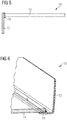
- FIG 5 illustrates a schematic sectional view of the inner part 10 of the oven door for the microwave oven according to a third embodiment of the present invention.
- the third embodiment has similar geometric properties as the second embodiment of the present invention.
- the inner part 10 of the oven door includes the door cover 12 and the inner glass panel 14, wherein the door cover 12 encloses the inner glass panel 14.
- the inner glass panel 14 faces the oven cavity of the microwave oven in the closed state of the oven door.
- the gasket is provided between the inner glass panel 14 and the oven cavity, wherein the gasket touches the inner glass panel 14 in the closed state of the oven door.
- the gasket may be made of silicone or mesh. Mesh is suitable for pyrolytic ovens.
- the door cover 12 has the I-shaped cross-section, wherein said I-shaped cross-section of the door cover 12 extends perpendicular to the plane of the inner glass panel 14.
- the welded joint 16 is formed in the overlap area of the inner side of the door cover 12 and the circumferential side of the inner glass panel 14.
- the circumferential side of the inner glass panel 14 is connected to the inner side of the door cover 12 by the welded joint 16.
- the welded joint 16 allows the high temperature resistance and the tight connection between the door cover 12 and the inner glass panel 14.
- the welded joint 16 provides an improved design of the inner part 10 of the oven door.
- the welded joint 16 represented in FIG 5 is bigger than the real welded joint 16. In practice, the welded joint 16 is smaller than the representation in FIG 5 .
- the door cover 12 is made of metal.
- the door cover 12 is made of aluminium or stainless steel.
- the door cover 12 according to the present invention may have an arbitrary shape, which is suitable for providing the overlap area with the glass panel 14.
- FIG 6 illustrates a schematic sectional perspective view of the inner part 10 of the oven door for the microwave oven according to the prior art.
- the inner part 10 of the oven door includes the door cover 12 and the inner glass panel 14.
- the door cover 12 encloses the inner glass panel 14.
- the inner glass panel 14 faces directly the oven cavity of the microwave oven in the closed state of the oven door.
- the door cover 12 has the L-shaped cross-section.
- the inner leg of said L-shaped cross-section extends parallel to the plane of the inner glass panel 14, while the outer leg of the L-shaped cross-section encloses the inner leg, is arranged perpendicular to said inner leg and extends outwards from the inner leg.
- the inner leg of the door cover 12 and the outer portion of the inner surface of the inner glass panel 14 overlap. In the overlap area of the inner leg of the door cover 12 and the inner glass panel 14, said door cover 12 and inner glass panel 14 are glued together.
- a glue joint 18 is formed in the overlap area of the inner leg of the door cover 12 and the inner glass panel 14.
- the outer portion of the inner surface of the inner glass panel 14 is connected to an outer side of the inner leg of the door cover 12 by the glue joint 18.
- the inner part 10 of the oven door according to the prior art includes the glue joint 18 instead of the welded joint 16 according to the present invention.
Landscapes
- Physics & Mathematics (AREA)
- Electromagnetism (AREA)
- Electric Ovens (AREA)
- Special Wing (AREA)
Priority Applications (6)
| Application Number | Priority Date | Filing Date | Title |
|---|---|---|---|
| EP16205547.9A EP3340739B1 (fr) | 2016-12-20 | 2016-12-20 | Porte de four à micro-ondes |
| BR112019012112-9A BR112019012112A2 (pt) | 2016-12-20 | 2017-11-24 | porta de forno para um forno de micro-ondas ou um forno de cozinha e forno de micro-ondas ou um forno de cozinha com funções de aquecimento por micro-ondas |
| AU2017381020A AU2017381020A1 (en) | 2016-12-20 | 2017-11-24 | Oven door for a microwave oven |
| CN201780077844.8A CN110073722A (zh) | 2016-12-20 | 2017-11-24 | 用于微波炉的炉门 |
| US16/464,388 US11039509B2 (en) | 2016-12-20 | 2017-11-24 | Oven door for a microwave oven |
| PCT/EP2017/080343 WO2018114218A1 (fr) | 2016-12-20 | 2017-11-24 | Porte de four pour four à micro-ondes |
Applications Claiming Priority (1)
| Application Number | Priority Date | Filing Date | Title |
|---|---|---|---|
| EP16205547.9A EP3340739B1 (fr) | 2016-12-20 | 2016-12-20 | Porte de four à micro-ondes |
Publications (2)
| Publication Number | Publication Date |
|---|---|
| EP3340739A1 true EP3340739A1 (fr) | 2018-06-27 |
| EP3340739B1 EP3340739B1 (fr) | 2019-11-20 |
Family
ID=57570872
Family Applications (1)
| Application Number | Title | Priority Date | Filing Date |
|---|---|---|---|
| EP16205547.9A Not-in-force EP3340739B1 (fr) | 2016-12-20 | 2016-12-20 | Porte de four à micro-ondes |
Country Status (6)
| Country | Link |
|---|---|
| US (1) | US11039509B2 (fr) |
| EP (1) | EP3340739B1 (fr) |
| CN (1) | CN110073722A (fr) |
| AU (1) | AU2017381020A1 (fr) |
| BR (1) | BR112019012112A2 (fr) |
| WO (1) | WO2018114218A1 (fr) |
Cited By (1)
| Publication number | Priority date | Publication date | Assignee | Title |
|---|---|---|---|---|
| EP4543143A1 (fr) | 2023-10-20 | 2025-04-23 | Electrolux Appliances Aktiebolag | Porte de four pour un four ménager avec fonction de chauffage par micro-ondes |
Citations (3)
| Publication number | Priority date | Publication date | Assignee | Title |
|---|---|---|---|---|
| JPS5457553U (fr) * | 1977-09-29 | 1979-04-20 | ||
| JPS62299632A (ja) * | 1986-06-19 | 1987-12-26 | Matsushita Electric Ind Co Ltd | 高周波加熱装置 |
| EP0763964A2 (fr) * | 1995-09-18 | 1997-03-19 | Daewoo Electronics Co., Ltd | Porte d'un four à microondes ayant une structure de protection contre les microondes |
Family Cites Families (8)
| Publication number | Priority date | Publication date | Assignee | Title |
|---|---|---|---|---|
| US4206338A (en) * | 1976-02-12 | 1980-06-03 | Mills Products, Inc. | Self-contained window unit for oven doors (common cavity) |
| US4215258A (en) * | 1977-12-09 | 1980-07-29 | Minnesota Mining And Manufacturing Company | Microwave oven window construction |
| KR20040061559A (ko) * | 2002-12-31 | 2004-07-07 | 엘지전자 주식회사 | 모서리부가 강화된 전자레인지 |
| KR100543324B1 (ko) * | 2003-07-31 | 2006-01-20 | 삼성전자주식회사 | 전자렌지 |
| JP2013015254A (ja) * | 2011-07-04 | 2013-01-24 | Panasonic Corp | 加熱調理器 |
| CN102808568B (zh) * | 2012-07-25 | 2014-10-08 | 杭州老板电器股份有限公司 | 一种带隔热墙技术的电烤箱炉门结构 |
| CN203560965U (zh) * | 2013-10-29 | 2014-04-23 | 合肥荣事达三洋电器股份有限公司 | 微波炉 |
| CN103712251B (zh) * | 2013-12-16 | 2016-04-06 | 宁波方太厨具有限公司 | 一种微波炉门体结构及采用有该门体结构的微波炉 |
-
2016
- 2016-12-20 EP EP16205547.9A patent/EP3340739B1/fr not_active Not-in-force
-
2017
- 2017-11-24 WO PCT/EP2017/080343 patent/WO2018114218A1/fr not_active Ceased
- 2017-11-24 CN CN201780077844.8A patent/CN110073722A/zh active Pending
- 2017-11-24 BR BR112019012112-9A patent/BR112019012112A2/pt not_active Application Discontinuation
- 2017-11-24 US US16/464,388 patent/US11039509B2/en not_active Expired - Fee Related
- 2017-11-24 AU AU2017381020A patent/AU2017381020A1/en not_active Abandoned
Patent Citations (3)
| Publication number | Priority date | Publication date | Assignee | Title |
|---|---|---|---|---|
| JPS5457553U (fr) * | 1977-09-29 | 1979-04-20 | ||
| JPS62299632A (ja) * | 1986-06-19 | 1987-12-26 | Matsushita Electric Ind Co Ltd | 高周波加熱装置 |
| EP0763964A2 (fr) * | 1995-09-18 | 1997-03-19 | Daewoo Electronics Co., Ltd | Porte d'un four à microondes ayant une structure de protection contre les microondes |
Cited By (2)
| Publication number | Priority date | Publication date | Assignee | Title |
|---|---|---|---|---|
| EP4543143A1 (fr) | 2023-10-20 | 2025-04-23 | Electrolux Appliances Aktiebolag | Porte de four pour un four ménager avec fonction de chauffage par micro-ondes |
| WO2025082738A1 (fr) | 2023-10-20 | 2025-04-24 | Electrolux Appliances Aktiebolag | Porte de four pour four domestique à fonction de chauffage par micro-ondes |
Also Published As
| Publication number | Publication date |
|---|---|
| US11039509B2 (en) | 2021-06-15 |
| CN110073722A (zh) | 2019-07-30 |
| BR112019012112A2 (pt) | 2019-10-29 |
| AU2017381020A1 (en) | 2019-05-23 |
| US20200383180A1 (en) | 2020-12-03 |
| EP3340739B1 (fr) | 2019-11-20 |
| WO2018114218A1 (fr) | 2018-06-28 |
Similar Documents
| Publication | Publication Date | Title |
|---|---|---|
| EP2775794B1 (fr) | Porte pour appareil à micro-ondes | |
| US9750088B2 (en) | Oven door and a chassis for a microwave oven or an appliance with microwave heating function | |
| US10009964B2 (en) | Oven door for a microwave oven | |
| EP3477209B1 (fr) | Four comportant un dispositif d'imagerie | |
| CN104272867B (zh) | 用于遏制宽频带rf泄漏的多扼流器系统 | |
| US20120160830A1 (en) | Cooking appliance | |
| EP2815629B1 (fr) | Four à micro-ondes ou four multifonction avec fonction de chauffage à micro-ondes | |
| US11039509B2 (en) | Oven door for a microwave oven | |
| US20120167866A1 (en) | Window mounting for thermal expansion in an oven appliance | |
| EP3732397B1 (fr) | Appareil de cuisson | |
| KR20100012243A (ko) | 도어 및 이를 포함하는 전자레인지 | |
| CN207477396U (zh) | 一种电烤炉 |
Legal Events
| Date | Code | Title | Description |
|---|---|---|---|
| PUAI | Public reference made under article 153(3) epc to a published international application that has entered the european phase |
Free format text: ORIGINAL CODE: 0009012 |
|
| STAA | Information on the status of an ep patent application or granted ep patent |
Free format text: STATUS: THE APPLICATION HAS BEEN PUBLISHED |
|
| AK | Designated contracting states |
Kind code of ref document: A1 Designated state(s): AL AT BE BG CH CY CZ DE DK EE ES FI FR GB GR HR HU IE IS IT LI LT LU LV MC MK MT NL NO PL PT RO RS SE SI SK SM TR |
|
| AX | Request for extension of the european patent |
Extension state: BA ME |
|
| STAA | Information on the status of an ep patent application or granted ep patent |
Free format text: STATUS: REQUEST FOR EXAMINATION WAS MADE |
|
| 17P | Request for examination filed |
Effective date: 20190102 |
|
| RBV | Designated contracting states (corrected) |
Designated state(s): AL AT BE BG CH CY CZ DE DK EE ES FI FR GB GR HR HU IE IS IT LI LT LU LV MC MK MT NL NO PL PT RO RS SE SI SK SM TR |
|
| GRAP | Despatch of communication of intention to grant a patent |
Free format text: ORIGINAL CODE: EPIDOSNIGR1 |
|
| STAA | Information on the status of an ep patent application or granted ep patent |
Free format text: STATUS: GRANT OF PATENT IS INTENDED |
|
| INTG | Intention to grant announced |
Effective date: 20190618 |
|
| GRAA | (expected) grant |
Free format text: ORIGINAL CODE: 0009210 |
|
| STAA | Information on the status of an ep patent application or granted ep patent |
Free format text: STATUS: THE PATENT HAS BEEN GRANTED |
|
| GRAS | Grant fee paid |
Free format text: ORIGINAL CODE: EPIDOSNIGR3 |
|
| AK | Designated contracting states |
Kind code of ref document: B1 Designated state(s): AL AT BE BG CH CY CZ DE DK EE ES FI FR GB GR HR HU IE IS IT LI LT LU LV MC MK MT NL NO PL PT RO RS SE SI SK SM TR |
|
| REG | Reference to a national code |
Ref country code: GB Ref legal event code: FG4D |
|
| REG | Reference to a national code |
Ref country code: CH Ref legal event code: EP |
|
| REG | Reference to a national code |
Ref country code: DE Ref legal event code: R096 Ref document number: 602016024605 Country of ref document: DE |
|
| REG | Reference to a national code |
Ref country code: IE Ref legal event code: FG4D |
|
| REG | Reference to a national code |
Ref country code: AT Ref legal event code: REF Ref document number: 1205670 Country of ref document: AT Kind code of ref document: T Effective date: 20191215 |
|
| REG | Reference to a national code |
Ref country code: NL Ref legal event code: MP Effective date: 20191120 |
|
| REG | Reference to a national code |
Ref country code: LT Ref legal event code: MG4D |
|
| PG25 | Lapsed in a contracting state [announced via postgrant information from national office to epo] |
Ref country code: FI Free format text: LAPSE BECAUSE OF FAILURE TO SUBMIT A TRANSLATION OF THE DESCRIPTION OR TO PAY THE FEE WITHIN THE PRESCRIBED TIME-LIMIT Effective date: 20191120 Ref country code: NO Free format text: LAPSE BECAUSE OF FAILURE TO SUBMIT A TRANSLATION OF THE DESCRIPTION OR TO PAY THE FEE WITHIN THE PRESCRIBED TIME-LIMIT Effective date: 20200220 Ref country code: GR Free format text: LAPSE BECAUSE OF FAILURE TO SUBMIT A TRANSLATION OF THE DESCRIPTION OR TO PAY THE FEE WITHIN THE PRESCRIBED TIME-LIMIT Effective date: 20200221 Ref country code: SE Free format text: LAPSE BECAUSE OF FAILURE TO SUBMIT A TRANSLATION OF THE DESCRIPTION OR TO PAY THE FEE WITHIN THE PRESCRIBED TIME-LIMIT Effective date: 20191120 Ref country code: LV Free format text: LAPSE BECAUSE OF FAILURE TO SUBMIT A TRANSLATION OF THE DESCRIPTION OR TO PAY THE FEE WITHIN THE PRESCRIBED TIME-LIMIT Effective date: 20191120 Ref country code: LT Free format text: LAPSE BECAUSE OF FAILURE TO SUBMIT A TRANSLATION OF THE DESCRIPTION OR TO PAY THE FEE WITHIN THE PRESCRIBED TIME-LIMIT Effective date: 20191120 Ref country code: NL Free format text: LAPSE BECAUSE OF FAILURE TO SUBMIT A TRANSLATION OF THE DESCRIPTION OR TO PAY THE FEE WITHIN THE PRESCRIBED TIME-LIMIT Effective date: 20191120 Ref country code: BG Free format text: LAPSE BECAUSE OF FAILURE TO SUBMIT A TRANSLATION OF THE DESCRIPTION OR TO PAY THE FEE WITHIN THE PRESCRIBED TIME-LIMIT Effective date: 20200220 |
|
| PG25 | Lapsed in a contracting state [announced via postgrant information from national office to epo] |
Ref country code: HR Free format text: LAPSE BECAUSE OF FAILURE TO SUBMIT A TRANSLATION OF THE DESCRIPTION OR TO PAY THE FEE WITHIN THE PRESCRIBED TIME-LIMIT Effective date: 20191120 Ref country code: RS Free format text: LAPSE BECAUSE OF FAILURE TO SUBMIT A TRANSLATION OF THE DESCRIPTION OR TO PAY THE FEE WITHIN THE PRESCRIBED TIME-LIMIT Effective date: 20191120 Ref country code: IS Free format text: LAPSE BECAUSE OF FAILURE TO SUBMIT A TRANSLATION OF THE DESCRIPTION OR TO PAY THE FEE WITHIN THE PRESCRIBED TIME-LIMIT Effective date: 20200320 |
|
| PG25 | Lapsed in a contracting state [announced via postgrant information from national office to epo] |
Ref country code: AL Free format text: LAPSE BECAUSE OF FAILURE TO SUBMIT A TRANSLATION OF THE DESCRIPTION OR TO PAY THE FEE WITHIN THE PRESCRIBED TIME-LIMIT Effective date: 20191120 |
|
| PG25 | Lapsed in a contracting state [announced via postgrant information from national office to epo] |
Ref country code: EE Free format text: LAPSE BECAUSE OF FAILURE TO SUBMIT A TRANSLATION OF THE DESCRIPTION OR TO PAY THE FEE WITHIN THE PRESCRIBED TIME-LIMIT Effective date: 20191120 Ref country code: PT Free format text: LAPSE BECAUSE OF FAILURE TO SUBMIT A TRANSLATION OF THE DESCRIPTION OR TO PAY THE FEE WITHIN THE PRESCRIBED TIME-LIMIT Effective date: 20200412 Ref country code: DK Free format text: LAPSE BECAUSE OF FAILURE TO SUBMIT A TRANSLATION OF THE DESCRIPTION OR TO PAY THE FEE WITHIN THE PRESCRIBED TIME-LIMIT Effective date: 20191120 Ref country code: CZ Free format text: LAPSE BECAUSE OF FAILURE TO SUBMIT A TRANSLATION OF THE DESCRIPTION OR TO PAY THE FEE WITHIN THE PRESCRIBED TIME-LIMIT Effective date: 20191120 Ref country code: RO Free format text: LAPSE BECAUSE OF FAILURE TO SUBMIT A TRANSLATION OF THE DESCRIPTION OR TO PAY THE FEE WITHIN THE PRESCRIBED TIME-LIMIT Effective date: 20191120 Ref country code: ES Free format text: LAPSE BECAUSE OF FAILURE TO SUBMIT A TRANSLATION OF THE DESCRIPTION OR TO PAY THE FEE WITHIN THE PRESCRIBED TIME-LIMIT Effective date: 20191120 |
|
| REG | Reference to a national code |
Ref country code: CH Ref legal event code: PL |
|
| REG | Reference to a national code |
Ref country code: AT Ref legal event code: MK05 Ref document number: 1205670 Country of ref document: AT Kind code of ref document: T Effective date: 20191120 |
|
| REG | Reference to a national code |
Ref country code: DE Ref legal event code: R097 Ref document number: 602016024605 Country of ref document: DE |
|
| REG | Reference to a national code |
Ref country code: BE Ref legal event code: MM Effective date: 20191231 |
|
| PG25 | Lapsed in a contracting state [announced via postgrant information from national office to epo] |
Ref country code: MC Free format text: LAPSE BECAUSE OF FAILURE TO SUBMIT A TRANSLATION OF THE DESCRIPTION OR TO PAY THE FEE WITHIN THE PRESCRIBED TIME-LIMIT Effective date: 20191120 Ref country code: SM Free format text: LAPSE BECAUSE OF FAILURE TO SUBMIT A TRANSLATION OF THE DESCRIPTION OR TO PAY THE FEE WITHIN THE PRESCRIBED TIME-LIMIT Effective date: 20191120 Ref country code: SK Free format text: LAPSE BECAUSE OF FAILURE TO SUBMIT A TRANSLATION OF THE DESCRIPTION OR TO PAY THE FEE WITHIN THE PRESCRIBED TIME-LIMIT Effective date: 20191120 |
|
| PLBE | No opposition filed within time limit |
Free format text: ORIGINAL CODE: 0009261 |
|
| STAA | Information on the status of an ep patent application or granted ep patent |
Free format text: STATUS: NO OPPOSITION FILED WITHIN TIME LIMIT |
|
| 26N | No opposition filed |
Effective date: 20200821 |
|
| PG25 | Lapsed in a contracting state [announced via postgrant information from national office to epo] |
Ref country code: LU Free format text: LAPSE BECAUSE OF NON-PAYMENT OF DUE FEES Effective date: 20191220 Ref country code: IE Free format text: LAPSE BECAUSE OF NON-PAYMENT OF DUE FEES Effective date: 20191220 Ref country code: FR Free format text: LAPSE BECAUSE OF NON-PAYMENT OF DUE FEES Effective date: 20200120 |
|
| PG25 | Lapsed in a contracting state [announced via postgrant information from national office to epo] |
Ref country code: LI Free format text: LAPSE BECAUSE OF NON-PAYMENT OF DUE FEES Effective date: 20191231 Ref country code: PL Free format text: LAPSE BECAUSE OF FAILURE TO SUBMIT A TRANSLATION OF THE DESCRIPTION OR TO PAY THE FEE WITHIN THE PRESCRIBED TIME-LIMIT Effective date: 20191120 Ref country code: BE Free format text: LAPSE BECAUSE OF NON-PAYMENT OF DUE FEES Effective date: 20191231 Ref country code: CH Free format text: LAPSE BECAUSE OF NON-PAYMENT OF DUE FEES Effective date: 20191231 Ref country code: AT Free format text: LAPSE BECAUSE OF FAILURE TO SUBMIT A TRANSLATION OF THE DESCRIPTION OR TO PAY THE FEE WITHIN THE PRESCRIBED TIME-LIMIT Effective date: 20191120 Ref country code: SI Free format text: LAPSE BECAUSE OF FAILURE TO SUBMIT A TRANSLATION OF THE DESCRIPTION OR TO PAY THE FEE WITHIN THE PRESCRIBED TIME-LIMIT Effective date: 20191120 |
|
| PG25 | Lapsed in a contracting state [announced via postgrant information from national office to epo] |
Ref country code: CY Free format text: LAPSE BECAUSE OF FAILURE TO SUBMIT A TRANSLATION OF THE DESCRIPTION OR TO PAY THE FEE WITHIN THE PRESCRIBED TIME-LIMIT Effective date: 20191120 |
|
| PG25 | Lapsed in a contracting state [announced via postgrant information from national office to epo] |
Ref country code: MT Free format text: LAPSE BECAUSE OF FAILURE TO SUBMIT A TRANSLATION OF THE DESCRIPTION OR TO PAY THE FEE WITHIN THE PRESCRIBED TIME-LIMIT Effective date: 20191120 Ref country code: HU Free format text: LAPSE BECAUSE OF FAILURE TO SUBMIT A TRANSLATION OF THE DESCRIPTION OR TO PAY THE FEE WITHIN THE PRESCRIBED TIME-LIMIT; INVALID AB INITIO Effective date: 20161220 |
|
| GBPC | Gb: european patent ceased through non-payment of renewal fee |
Effective date: 20201220 |
|
| PG25 | Lapsed in a contracting state [announced via postgrant information from national office to epo] |
Ref country code: GB Free format text: LAPSE BECAUSE OF NON-PAYMENT OF DUE FEES Effective date: 20201220 |
|
| PGFP | Annual fee paid to national office [announced via postgrant information from national office to epo] |
Ref country code: DE Payment date: 20211210 Year of fee payment: 6 |
|
| PG25 | Lapsed in a contracting state [announced via postgrant information from national office to epo] |
Ref country code: TR Free format text: LAPSE BECAUSE OF FAILURE TO SUBMIT A TRANSLATION OF THE DESCRIPTION OR TO PAY THE FEE WITHIN THE PRESCRIBED TIME-LIMIT Effective date: 20191120 |
|
| PGFP | Annual fee paid to national office [announced via postgrant information from national office to epo] |
Ref country code: IT Payment date: 20211224 Year of fee payment: 6 |
|
| PG25 | Lapsed in a contracting state [announced via postgrant information from national office to epo] |
Ref country code: MK Free format text: LAPSE BECAUSE OF FAILURE TO SUBMIT A TRANSLATION OF THE DESCRIPTION OR TO PAY THE FEE WITHIN THE PRESCRIBED TIME-LIMIT Effective date: 20191120 |
|
| REG | Reference to a national code |
Ref country code: DE Ref legal event code: R119 Ref document number: 602016024605 Country of ref document: DE |
|
| PG25 | Lapsed in a contracting state [announced via postgrant information from national office to epo] |
Ref country code: DE Free format text: LAPSE BECAUSE OF NON-PAYMENT OF DUE FEES Effective date: 20230701 |
|
| PG25 | Lapsed in a contracting state [announced via postgrant information from national office to epo] |
Ref country code: IT Free format text: LAPSE BECAUSE OF NON-PAYMENT OF DUE FEES Effective date: 20221220 |