EP3341171B1 - Ständerplatte zur formung einer ständeranordnung - Google Patents
Ständerplatte zur formung einer ständeranordnung Download PDFInfo
- Publication number
- EP3341171B1 EP3341171B1 EP16842757.3A EP16842757A EP3341171B1 EP 3341171 B1 EP3341171 B1 EP 3341171B1 EP 16842757 A EP16842757 A EP 16842757A EP 3341171 B1 EP3341171 B1 EP 3341171B1
- Authority
- EP
- European Patent Office
- Prior art keywords
- edge
- buck
- foam portion
- support beam
- internal surface
- Prior art date
- Legal status (The legal status is an assumption and is not a legal conclusion. Google has not performed a legal analysis and makes no representation as to the accuracy of the status listed.)
- Active
Links
Images



Classifications
-
- E—FIXED CONSTRUCTIONS
- E06—DOORS, WINDOWS, SHUTTERS, OR ROLLER BLINDS IN GENERAL; LADDERS
- E06B—FIXED OR MOVABLE CLOSURES FOR OPENINGS IN BUILDINGS, VEHICLES, FENCES OR LIKE ENCLOSURES IN GENERAL, e.g. DOORS, WINDOWS, BLINDS, GATES
- E06B1/00—Border constructions of openings in walls, floors, or ceilings; Frames to be rigidly mounted in such openings
- E06B1/02—Base frames, i.e. template frames for openings in walls or the like, provided with means for securing a further rigidly-mounted frame; Special adaptations of frames to be fixed therein
-
- E—FIXED CONSTRUCTIONS
- E04—BUILDING
- E04B—GENERAL BUILDING CONSTRUCTIONS; WALLS, e.g. PARTITIONS; ROOFS; FLOORS; CEILINGS; INSULATION OR OTHER PROTECTION OF BUILDINGS
- E04B2/00—Walls, e.g. partitions, for buildings; Wall construction with regard to insulation; Connections specially adapted to walls
- E04B2/84—Walls made by casting, pouring, or tamping in situ
- E04B2/86—Walls made by casting, pouring, or tamping in situ made in permanent forms
-
- E—FIXED CONSTRUCTIONS
- E06—DOORS, WINDOWS, SHUTTERS, OR ROLLER BLINDS IN GENERAL; LADDERS
- E06B—FIXED OR MOVABLE CLOSURES FOR OPENINGS IN BUILDINGS, VEHICLES, FENCES OR LIKE ENCLOSURES IN GENERAL, e.g. DOORS, WINDOWS, BLINDS, GATES
- E06B1/00—Border constructions of openings in walls, floors, or ceilings; Frames to be rigidly mounted in such openings
- E06B1/04—Frames for doors, windows, or the like to be fixed in openings
- E06B1/32—Frames composed of parts made of different materials
-
- E—FIXED CONSTRUCTIONS
- E04—BUILDING
- E04B—GENERAL BUILDING CONSTRUCTIONS; WALLS, e.g. PARTITIONS; ROOFS; FLOORS; CEILINGS; INSULATION OR OTHER PROTECTION OF BUILDINGS
- E04B2/00—Walls, e.g. partitions, for buildings; Wall construction with regard to insulation; Connections specially adapted to walls
- E04B2/84—Walls made by casting, pouring, or tamping in situ
- E04B2/86—Walls made by casting, pouring, or tamping in situ made in permanent forms
- E04B2002/8676—Wall end details
Definitions
- US2014/130431 A1 describes an insulated window buck with integrated fastening and anchor elements for a self aligning cut or molded insulated concrete form (ICF) window buck.
- ICF insulated concrete form
- ICFs insulating concrete forms
- rebar horizontal and vertical reinforcing rods
- Window and door openings in the concrete walls are framed prior to pouring the concrete.
- Window or door bucks are frames that provide the rough structure and opening into which the window or door will be installed. Bucks are also used to form bulkheads. Bucks have typically been constructed of materials such as wood, plastic, and steel. However, in concrete walls formed using insulated block systems, such bucks can be difficult to install and use because the bucks lack continuity of material with the insulating concrete forms. Insulating concrete form bucks have been developed; however, there remains room for improvement in terms of ease of installation and use.
- inventive concept is not limited in its application to the details of construction, and/or the arrangement of the components set forth in the following description, or illustrated in the drawings.
- inventive concept is capable of other embodiments or of being practiced or carried out in various ways.
- phraseology and terminology employed herein is for purpose of description only and should not be regarded as limiting in anyway.
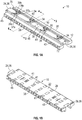
- the buck panel 10 is adapted to be interconnected with other panels to form a buck to frame an opening in a wall for receiving a window or a door or to form a bulkhead.
- the buck panel 10 has a foam portion 12, a central support beam 14, a first lateral support beam 16, and a second lateral support beam 18.
- the foam portion 12 has an internal surface 20, an exterior surface 22, a first end 24, a second end 26 opposite the first end 24, a first side 28, a second side 30 opposite the first side 28 and separated from the first side 28 by a center portion 32.
- a plurality of rebar holding members 34 extend outwardly from the internal surface 20 along the center portion 32.
- the second end 26 includes a recessed portion 36 that is matingly receivable of a protruding portion 38 of a first end of a like panel so that the buck panel 10 can be interconnected with the like panel in both a parallel and a right-angle end-to-end relationship.
- the central support beam 14 is positioned longitudinally and molded within the center portion 32 of the foam portion 12.
- the central support beam includes a plurality of wings 40 protruding from the internal surface 20 of the foam portion 12.
- the first lateral support beam 16 is positioned longitudinally and molded within the foam portion 12 near the first side 28 of the foam portion 12.
- the second lateral support beam 18 is positioned longitudinally and molded within the foam portion 12 near the second side 30 of the foam portion 12.
- the foam portion of the buck panel 10 may be formed of a fire retardant expanded polypropylene, polystyrene, polyethylene or other suitable polymers.
- the foam portion 12 is formed of expanded polystyrene commonly referred to as "EPS.”
- the internal surface 20 of the foam portion 12 is designed to face a cavity of an insulating concrete block form during construction of a wall with an opening such as for a door or window. As shown in FIG. 1A , the internal surface 20 can include advertising indicia, instructions, and guides.
- the internal surface 20 is shaped during molding to form the plurality of rebar holding members 34.
- Each of the rebar holding members 34 may include one or more seats for rebar positioning. More particularly, seats 37a and 37b are defined by restraining fingers 39a, 39b, and 39c. The seats 37a and 37b may be dimensioned to receive one or more pieces of rebar (not shown) in a stacked orientation.
- the restraining fingers 39a, 39b, and 39c are spaced from one another such that the compressibility and resiliency of the foam portion 12 allows the restraining fingers 39a, 39b, and 39c to frictionally grip rebar positioned in the seats 37a and 37b.
- the exterior surface 22 is substantially planar and uniform in configuration.
- the exterior surface 22 is intended to face the opening for the door or window and can include advertising indicia as well as instructions and guides. Areas that can accept screws or nails can be indicated by markings 41 on the exterior surface 22 to assist a builder in finishing the window or door within the buck formed by buck panels 10.
- FIG. 2A illustrates another embodiment of a buck panel 10a.
- the buck panel 10a is similar in construction to the buck panel 10 except as described below.
- the buck panel 10a has a width that is greater than the width of the buck panel 10.
- the buck panel 10 has a restraining finger 39d having a width greater than the width of the restraining finger 39b.
- FIG. 2B illustrates another embodiment of a buck panel 10b.
- the buck panel 10b is similar in construction to the buck panel 10b except the buck panel 10b is formed without any restraining fingers.
- markings 43 may be provided along the first side 28 and the second side 30 of the foam portion 12 to indicate length. Such markings may serve as guidelines for assisting the installer to cut the buck panel 10 to a desired size.
- the markings 43 may be spaced at one inch intervals; however, it will be appreciated that other intervals may be used.
- some or all of the markings 43 may be identified with numerals, similar to a measuring tape. This allows an installer to cut the buck panels 10 without the need of marking the cut point on the panel, or may eliminate the need to measure the form during the installation or cutting process of installation.
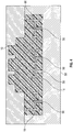
- the first side 28 and the second side 30 may further be marked (as indicated with dashed markings 45) to indicate the upper and lower boundaries of the first lateral support beam 16 and the second lateral support beam 18, respectively.
- the first lateral support beam 16 and the second lateral support beam 18 provide attachment points along the length of the first side 28 and the second side 30 of the buck panel 10 in a manner to be described below.
- the central support beam 14 is positioned longitudinally within the center portion 32 of the foam portion 12.
- the central support beam 14 is molded in multiple sections.
- the central support beam 14 can be molded in two 2-foot long sections 14a for insertion into a four foot long buck panel 10.
- FIG. 5 illustrates one of the central support beam sections 14a.
- Each of the central support beam sections 14a may include a first edge 42, a second edge 44, and plates 46 connecting the first edge 42 and second edge 44.
- the plates 46 extend in a perpendicular relationship relative to the first edge 42 and the second edge 44.
- the central support beam sections 14a have a plurality of wings 40 extending from the first edge 42 and the second edge 44.
- the wings 40 are configured to protrude a predetermined distance from the internal surface 20 of the foam portion 12 in a way that the wings 40 will be received in the concrete to provide anchor points when the concrete is poured.
- the wings 40 are substantially l-shaped. As such, the wings 40 have a pair of opposing protrusions 47 for anchoring to the concrete. It will be appreciated, however, that the wings 40 may be configured in a variety of shapes.
- the wings 40 extend from the internal surface 20 of the foam portion 12 in a laterally offset relationship relative to the seats 37a and 37b.
- the central support beam sections 14a can be made of any suitable material providing a physical strength and rigidity necessary for the buck panel 10 and for securing attachment devices such as nails and screws for final construction and support of the window or door.
- the wings 40 may each include a hole 48 ( FIG. 5 ).
- the holes 48 can be used during construction to tie the buck panel 10 to an adjacent block to prevent the buck panel 10 from floating or moving when the concrete is poured.
- a wire can be threaded through the holes 48 in wing 40 and tied to a web of an adjacent block.
- the holes 48 can be used to secure rebar positioned in rebar holding members 34 in place by stringing a wire through the holes 48 and securing the wire to the rebar.
- each central support beam section 14a may have first ends 50 insertable or otherwise connectable with corresponding second ends 52 of a like central support beam section 14b.
- the use and molding of two shorter connectable central support beam sections can be more economical than molding a single longer central support beam.
- At least two of the central support beam 14 plates 46 include one or more pin holes 54. As shown in FIG. 4 , when molding the buck panel 10, pins 56 extend a predetermined distance from a mold insert side 58 and through the pin holes 54 to hold the central support beam 14 in place during the molding process.
- First and second lateral support beams 16 and 18, respectively, can be identical and can be made of any suitable material providing a physical strength and rigidity necessary for the buck panel 10 and for securing attachment devices such as nails and screws, for final construction and support of the window or door.
- the first and second lateral support beams 16 and 18 can be molded in multiple sections.
- the first lateral support beam 16 can be molded in two 2-foot long sections 16a for use in a 4-foot long buck panel 10.
- each lateral support beam section 16a includes first ends 66 that can be inserted into or otherwise connected to corresponding second ends 68 of a like lateral support beam section.
- the first lateral support beam 16 may have a first edge 60 and a second edge 62 connected by a plurality of plates 64.
- the markings 41 on the exterior surface 22 of the foam portion 12 for indicating attachment points more particularly correspond to the position of the plates 46 of the central support beam 14 and the plates 64 of the first and second lateral support beams 16 and 18.
- the markings 45 on the first side 28 and the second side 30 indicate the upper and lower boundaries of the first edge 60 and the second edge 62 of the first and second lateral support beams 16 and 18, respectively.
- At least two of the lateral support beam plates 64 include a pin hole 54 to hold the first lateral support beam 16 in place during the molding process.
- pins 56 extend through the mold insert side 58 of the mold and through the pin holes 54 to hold the first lateral support beam 16 in place during the molding process.
- the pins 56 can be tapered to help in positioning within the pin holes 54.
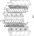
- An exemplary mold assembly for forming the buck panel 10 is shown in FIG. 7 .
- the foam portion 12 further comprises a first alignment lip 70 and a second alignment lip 72 proportioned and positioned to fit within a cavity of an insulating concrete block form (not shown) to align and support the buck panel 10 relative to an adjacent concrete form block during the construction process.
Landscapes
- Engineering & Computer Science (AREA)
- Civil Engineering (AREA)
- Structural Engineering (AREA)
- Architecture (AREA)
- Physics & Mathematics (AREA)
- Electromagnetism (AREA)
- Forms Removed On Construction Sites Or Auxiliary Members Thereof (AREA)
- Building Environments (AREA)
- Acoustics & Sound (AREA)
- Load-Bearing And Curtain Walls (AREA)
Claims (15)
- Ständerplatte (10), die geeignet ist, mit anderen Platten verbunden zu werden, um einen Ständer zum Einfassen einer Trennwand oder einer Öffnung in einer Wand zum Aufnehmen eines Fensters oder einer Tür zu bilden, wobei die Ständerplatte Folgendes umfasst:einen Schaumstoffabschnitt (12), der eine Innenfläche (20), eine Außenfläche (22), ein erstes Ende (24), ein dem ersten Ende gegenüberliegendes zweites Ende (26), eine erste Seite (28), eine der ersten Seite gegenüberliegende zweite Seite (30) und einen mittleren Abschnitt (32), der sich zwischen der ersten Seite und der zweiten Seite befindet, aufweist,gekennzeichnet durch:einen mittleren Stützbalken (14), der sich in Längsrichtung in dem mittleren Abschnitt des Schaumstoffabschnitts befindet, wobei der mittlere Stützbalken einen ersten Rand (42), einen zweiten Rand (44), eine Vielzahl von Platten (46), die sich zwischen dem ersten Rand und dem zweiten Rand erstrecken und mit denselben verbunden sind, und eine Vielzahl von Flügeln (40) aufweist, die sich auf eine solche Weise von dem ersten Rand und dem zweiten Rand rechtwinklig zu der Innenfläche des Schaumstoffabschnitts erstrecken, dass ein Abschnitt der Flügel von der Innenfläche des Schaumstoffabschnitts vorsteht, um in Beton aufgenommen zu werden, der über die Innenfläche gegossen wird,einen ersten seitlichen Stützbalken (16), der sich in Längsrichtung in dem Schaumstoffabschnitt nahe der ersten Seite des Schaumstoffabschnitts befindet und von dem mittleren Stützbalken beabstandet ist, wobei der erste seitliche Stützbalken einen ersten Rand, einen zweiten Rand und eine Vielzahl von Platten aufweist, die sich zwischen dem ersten Rand und dem zweiten Rand erstrecken und mit denselben verbunden sind, undeinen zweiten seitlichen Stützbalken (18), der sich in Längsrichtung in dem Schaumstoffabschnitt nahe der zweiten Seite des Schaumstoffabschnitts befindet und von dem mittleren Stützbalken beabstandet ist, wobei der zweite seitliche Stützbalken einen ersten Rand, einen zweiten Rand und eine Vielzahl von Platten aufweist, die sich zwischen dem ersten Rand und dem zweiten Rand erstrecken und mit denselben verbunden sind.
- Ständerplatte nach Anspruch 1, wobei der Schaumstoffabschnitt ferner eine erste Ausrichtungslippe (70) und eine zweite Ausrichtungslippe (72) umfasst, die sich um einen vorgegebenen Abstand von der Innenfläche nach außen erstrecken, wobei die erste Ausrichtungslippe und die zweite Ausrichtungslippe um einen vorgegebenen Abstand voneinander beabstandet sind, um gepaart in einen Hohlraum einer Isolierbetonblockform zu passen.
- Ständerplatte nach Anspruch 1, wobei die Vielzahl von Flügeln im Wesentlichen I-förmig ist.
- Ständerplatte nach Anspruch 1, wobei die Flügel ein Loch (48) durch den Abschnitt des Flügels aufweisen, der von der Innenfläche des Schaumstoffabschnitts vorsteht.
- Ständerplatte nach Anspruch 1, wobei sich wenigstens ein Abschnitt der Innenfläche des Schaumstoffs um einen vorgegebenen Abstand nach außen erstreckt, um eine Vielzahl von Betonstahlhalteelementen (34) zu bilden, die sich entlang dem mittleren Abschnitt befinden, und wobei die Vielzahl von Betonstahlhalteelementen mit einem ersten Sitz (37a) und einem zweiten Sitz (37b) versehen ist, die durch vorgegebene Räume zwischen einem ersten festhaltenden Finger (39a), einem zweiten festhaltenden Finger (39b) und einem dritten festhaltenden Finger (39c) definiert sind.
- Ständerplatte nach Anspruch 5, wobei die vorgegebenen Räume zwischen dem ersten festhaltenden Finger, dem zweiten festhaltenden Finger und dem dritten festhaltenden Finger auf eine solche Weise dimensioniert sind, dass die Komprimierbarkeit und die Elastizität des Schaumstoffabschnitts ermöglichen, dass der erste festhaltende Finger, der zweite festhaltende Finger und der dritte festhaltende Finger den Betonstahl, der sich in dem ersten Sitz und dem zweiten Sitz befindet, reibschlüssig ergreifen.
- Ständerplatte nach Anspruch 5, wobei die Vielzahl von Flügeln relativ zu dem ersten Sitz und dem zweiten Sitz der Vielzahl von Betonstahlhalteelementen seitlich versetzt ist.
- Ständerplatte nach Anspruch 1, wobei die erste Seite des Schaumstoffabschnitts ferner eine Vielzahl von Markierungen (43) umfasst, die eine obere und eine untere Grenze des ersten Rands des ersten seitlichen Stützbalkens anzeigen, und die zweite Seite des Schaumstoffabschnitts ferner eine Vielzahl von Markierungen (43) umfasst, die eine obere und eine untere Grenze des zweiten Rands des zweiten seitlichen Stützbalkens anzeigen.
- Ständerplatte (10), die geeignet ist, mit anderen Platten verbunden zu werden, um einen Ständer zum Einfassen einer Trennwand oder einer Öffnung in einer Wand zum Aufnehmen eines Fensters oder einer Tür zu bilden, wobei die Ständerplatte Folgendes umfasst:
einen Schaumstoffabschnitt (12), der eine Innenfläche (20), eine Außenfläche (22), ein erstes Ende (24), ein dem ersten Ende gegenüberliegendes zweites Ende (26), eine erste Seite (28), eine der ersten Seite gegenüberliegende zweite Seite (30) und einen mittleren Abschnitt (30), der sich zwischen der ersten Seite und der zweiten Seite befindet, aufweist, wobei sich wenigstens ein Abschnitt der Innenfläche um einen vorgegebenen Abstand nach außen erstreckt, um eine Vielzahl von Betonstahlhalteelementen (34) zu bilden, die sich entlang dem mittleren Abschnitt befinden, und gekennzeichnet durch:
einen Stützbalken (14), der sich in Längsrichtung in dem Schaumstoffabschnitt befindet, wobei der Stützbalken einen ersten Rand (42), einen zweiten Rand (44), eine Vielzahl von Platten (46), die sich zwischen dem ersten Rand und dem zweiten Rand erstrecken und mit denselben verbunden sind, und eine Vielzahl von Flügeln (40) aufweist, die sich auf eine solche Weise von dem ersten Rand und dem zweiten Rand rechtwinklig zu der Innenfläche des Schaumstoffabschnitts erstrecken, dass ein Abschnitt der Flügel von der Innenfläche des Schaumstoffabschnitts vorsteht, um in Beton aufgenommen zu werden, der über die Innenfläche gegossen wird. - Ständerplatte nach Anspruch 9, wobei der Schaumstoffabschnitt ferner eine erste Ausrichtungslippe (70) und eine zweite Ausrichtungslippe (72) umfasst, die sich um einen vorgegebenen Abstand von der Innenfläche nach außen erstrecken, wobei die erste Ausrichtungslippe und die zweite Ausrichtungslippe um einen vorgegebenen Abstand voneinander beabstandet sind, um gepaart in einen Hohlraum einer Isolierbetonblockform zu passen.
- Ständerplatte nach Anspruch 9, wobei die Vielzahl von Flügeln im Wesentlichen I-förmig ist.
- Ständerplatte nach Anspruch 9, wobei die Flügel ein Loch (48) durch den Abschnitt des Flügels aufweisen, der von der Innenfläche des Schaumstoffabschnitts vorsteht.
- Ständerplatte nach Anspruch 9, wobei die Vielzahl von Betonstahlhalteelementen mit einem ersten Sitz (37a) und einem zweiten Sitz (37b) versehen ist, die durch vorgegebene Räume zwischen einem ersten festhaltenden Finger (39a), einem zweiten festhaltenden Finger (39b) und einem dritten festhaltenden Finger (39c) definiert sind.
- Ständerplatte nach Anspruch 13, wobei die vorgegebenen Räume zwischen dem ersten festhaltenden Finger, dem zweiten festhaltenden Finger und dem dritten festhaltenden Finger auf eine solche Weise dimensioniert sind, dass die Komprimierbarkeit und die Elastizität des Schaumstoffabschnitts ermöglichen, dass der erste festhaltende Finger, der zweite festhaltende Finger und der dritte festhaltende Finger den Betonstahl, der sich in dem ersten Sitz und dem zweiten Sitz befindet, reibschlüssig ergreifen.
- Ständerplatte nach Anspruch 13, wobei die Vielzahl von Flügeln relativ zu dem ersten Sitz und dem zweiten Sitz der Vielzahl von Betonstahlhalteelementen seitlich versetzt ist.
Applications Claiming Priority (2)
| Application Number | Priority Date | Filing Date | Title |
|---|---|---|---|
| US201562211072P | 2015-08-28 | 2015-08-28 | |
| PCT/US2016/049284 WO2017040409A1 (en) | 2015-08-28 | 2016-08-29 | Buck panel for forming a buck assembly |
Publications (3)
| Publication Number | Publication Date |
|---|---|
| EP3341171A1 EP3341171A1 (de) | 2018-07-04 |
| EP3341171A4 EP3341171A4 (de) | 2019-05-01 |
| EP3341171B1 true EP3341171B1 (de) | 2020-04-29 |
Family
ID=58097660
Family Applications (1)
| Application Number | Title | Priority Date | Filing Date |
|---|---|---|---|
| EP16842757.3A Active EP3341171B1 (de) | 2015-08-28 | 2016-08-29 | Ständerplatte zur formung einer ständeranordnung |
Country Status (4)
| Country | Link |
|---|---|
| US (1) | US9850699B2 (de) |
| EP (1) | EP3341171B1 (de) |
| CA (1) | CA2996553C (de) |
| WO (1) | WO2017040409A1 (de) |
Families Citing this family (2)
| Publication number | Priority date | Publication date | Assignee | Title |
|---|---|---|---|---|
| US11248383B2 (en) * | 2018-09-21 | 2022-02-15 | Cooper E. Stewart | Insulating concrete form apparatus |
| US20240200390A1 (en) * | 2022-12-15 | 2024-06-20 | Gregory R. Steffes | Insulating concrete form buck |
Family Cites Families (33)
| Publication number | Priority date | Publication date | Assignee | Title |
|---|---|---|---|---|
| US2787820A (en) * | 1955-06-29 | 1957-04-09 | H & R Mfg Co | Window buck |
| DE1253088B (de) * | 1963-12-17 | 1967-10-26 | Eltro G M B H & Co Ges Fuer St | Verfahren zur Herstellung von Schiffskoerpern aus Schiffbauplatten |
| US4031285A (en) * | 1971-10-21 | 1977-06-21 | Miller Charles H | Lightweight, reinforced foamed organic polymer and cementitious material structure |
| FR2361512A1 (fr) * | 1976-08-12 | 1978-03-10 | Joannes Andre | Panneau de construction prefabrique et procede de fabrication |
| US4641469A (en) * | 1985-07-18 | 1987-02-10 | Wood Edward F | Prefabricated insulating panels |
| US4730422A (en) * | 1985-11-20 | 1988-03-15 | Young Rubber Company | Insulating non-removable type concrete wall forming structure and device and system for attaching wall coverings thereto |
| FR2647839B1 (fr) * | 1989-05-31 | 1991-09-20 | Durand Philippe | Elements prefabriques de coffrage et procede de construction de murs |
| CA2072781A1 (en) * | 1991-10-21 | 1993-04-22 | Jean-Guy Bergeron | Window frame |
| US5996293A (en) | 1996-09-20 | 1999-12-07 | Justin J. Anderson | Window buck and methods of assembly |
| US6070375A (en) | 1996-09-20 | 2000-06-06 | Anderson; Justin J. | Frame for a wall opening and methods of assembly and use |
| USRE43251E1 (en) | 1996-09-20 | 2012-03-20 | Anderson Justin J | Frame for a wall opening and methods of assembly and use |
| US6298622B1 (en) * | 1996-10-15 | 2001-10-09 | Plastedil, S.A. | Self-supporting construction element of expanded plastics, in particular for manufacturing floor elements and walls of buildings in general |
| US5896714A (en) * | 1997-03-11 | 1999-04-27 | Cymbala; Patrick M. | Insulating concrete form system |
| US6481178B2 (en) * | 1998-01-16 | 2002-11-19 | Eco-Block, Llc | Tilt-up wall |
| CA2244537C (en) | 1998-08-03 | 2007-10-23 | Aab Building System, Inc. | Buck for use with insulated concrete forms |
| CA2704828C (en) * | 1999-03-30 | 2012-09-25 | Arxx Building Products Inc. | Bridging member for concrete form walls |
| US6453620B1 (en) * | 2000-09-06 | 2002-09-24 | Michael J. Williams | Window buck |
| US20030005659A1 (en) | 2001-07-06 | 2003-01-09 | Moore, James D. | Buck system for concrete structures |
| US7490442B1 (en) | 2004-07-27 | 2009-02-17 | Feather Lite Innovations, Inc. | Window system for concrete walls and associated method |
| CA2585790C (en) * | 2004-12-07 | 2011-06-14 | Buildblock Building Systems, L.L.C. | Insulating concrete block |
| MX2008011077A (es) * | 2006-02-28 | 2009-03-03 | All Terior Systems Llc | Sistemas y metodos para acabado de un borde de una pared en forma de concreto aislado (icf). |
| US8561371B2 (en) * | 2006-03-14 | 2013-10-22 | Mute Wall Systems, Inc. | Barrier wall and method of forming wall panels between vertical wall stiffeners with support members extending partially through the wall panels |
| US8037652B2 (en) * | 2006-06-14 | 2011-10-18 | Encon Environmental Construction Solutions Inc. | Insulated concrete form |
| WO2008046177A1 (en) | 2006-10-20 | 2008-04-24 | Quad-Lock Building Systems Ltd. | Wall opening form |
| WO2009092158A1 (en) * | 2008-01-21 | 2009-07-30 | Octaform Systems Inc. | Stay-in-place form systems for windows and other building openings |
| CA2676344A1 (en) * | 2008-08-21 | 2010-02-21 | Gregory Westra | An improved buck system |
| US20100071306A1 (en) * | 2008-09-19 | 2010-03-25 | Kenneth Richard Williams | Reinforcing bracket for use with insulated concrete forms |
| CA2767939C (en) * | 2009-08-07 | 2018-01-02 | Buildblock Building Systems, Llc | Deck block |
| US9016011B2 (en) * | 2010-03-08 | 2015-04-28 | Gorilla Buck Inc. | Internally aligned insulating window and door buck |
| CA2795821C (en) * | 2010-04-27 | 2017-01-03 | Buildblock Building Systems, Llc | Web structure for knockdown insulating concrete block |
| US8931220B2 (en) | 2011-11-14 | 2015-01-13 | Gorilla Buck Inc. | Insulating ICF window buck with integrated fastening and anchors |
| US9109360B2 (en) | 2011-11-14 | 2015-08-18 | Gorilla Buck Inc. | Insulating fire and blast resistant window and door buck |
| US8495843B1 (en) * | 2012-04-20 | 2013-07-30 | Knut Horneland | Buck system |
-
2016
- 2016-08-29 EP EP16842757.3A patent/EP3341171B1/de active Active
- 2016-08-29 US US15/250,377 patent/US9850699B2/en active Active
- 2016-08-29 CA CA2996553A patent/CA2996553C/en active Active
- 2016-08-29 WO PCT/US2016/049284 patent/WO2017040409A1/en not_active Ceased
Non-Patent Citations (1)
| Title |
|---|
| None * |
Also Published As
| Publication number | Publication date |
|---|---|
| US9850699B2 (en) | 2017-12-26 |
| CA2996553A1 (en) | 2017-03-09 |
| EP3341171A4 (de) | 2019-05-01 |
| CA2996553C (en) | 2023-10-17 |
| EP3341171A1 (de) | 2018-07-04 |
| WO2017040409A1 (en) | 2017-03-09 |
| US20170058591A1 (en) | 2017-03-02 |
Similar Documents
| Publication | Publication Date | Title |
|---|---|---|
| US6279285B1 (en) | Insulated concrete wall system | |
| US7805906B2 (en) | Web structure for insulating concrete block | |
| US8887465B2 (en) | Apparatus and method for construction of structures utilizing insulated concrete forms | |
| US4894969A (en) | Insulating block form for constructing concrete wall structures | |
| US2316819A (en) | Wall structure | |
| US4562679A (en) | Holder of connecting bars for providing a positive connection of two structural members | |
| US20040200176A1 (en) | Concrete forming system and method | |
| US10753109B2 (en) | Concrete form tie, and concrete formwork comprising same | |
| US4329825A (en) | Reinforcing bar support for joining concrete structures | |
| CA2950219C (en) | Concrete formwork steel stud and system | |
| EP3443171B1 (de) | Konstruktionsanordnung | |
| US9091068B2 (en) | Wall construction system, wall stud, and method of installation | |
| EP3341171B1 (de) | Ständerplatte zur formung einer ständeranordnung | |
| GB2458317A (en) | Improvements in or relating to wall ties | |
| JP5965544B2 (ja) | Hバー、並びにこのhバー及び非金属製せき板を用いた型枠設置方法 | |
| US8266859B1 (en) | Concrete wall forming system | |
| CA3014571C (en) | Concrete form tie, and concrete formwork comprising same | |
| US20100193662A1 (en) | Form panel system for poured concrete | |
| WO2021110228A1 (en) | Modular mould system | |
| US3363373A (en) | Form tie | |
| KR200375941Y1 (ko) | 마디형 프렛타이 | |
| KR20180003005U (ko) | 거푸집용 간격 유지구 | |
| HU226877B1 (en) | Heat insulated block |
Legal Events
| Date | Code | Title | Description |
|---|---|---|---|
| STAA | Information on the status of an ep patent application or granted ep patent |
Free format text: STATUS: THE INTERNATIONAL PUBLICATION HAS BEEN MADE |
|
| PUAI | Public reference made under article 153(3) epc to a published international application that has entered the european phase |
Free format text: ORIGINAL CODE: 0009012 |
|
| STAA | Information on the status of an ep patent application or granted ep patent |
Free format text: STATUS: REQUEST FOR EXAMINATION WAS MADE |
|
| 17P | Request for examination filed |
Effective date: 20180327 |
|
| AK | Designated contracting states |
Kind code of ref document: A1 Designated state(s): AL AT BE BG CH CY CZ DE DK EE ES FI FR GB GR HR HU IE IS IT LI LT LU LV MC MK MT NL NO PL PT RO RS SE SI SK SM TR |
|
| AX | Request for extension of the european patent |
Extension state: BA ME |
|
| DAV | Request for validation of the european patent (deleted) | ||
| DAX | Request for extension of the european patent (deleted) | ||
| REG | Reference to a national code |
Ref country code: DE Ref legal event code: R079 Ref document number: 602016035353 Country of ref document: DE Free format text: PREVIOUS MAIN CLASS: B28B0007160000 Ipc: E04B0002860000 |
|
| A4 | Supplementary search report drawn up and despatched |
Effective date: 20190328 |
|
| RIC1 | Information provided on ipc code assigned before grant |
Ipc: E06B 1/02 20060101ALI20190322BHEP Ipc: E06B 1/32 20060101ALI20190322BHEP Ipc: E04B 2/86 20060101AFI20190322BHEP |
|
| STAA | Information on the status of an ep patent application or granted ep patent |
Free format text: STATUS: EXAMINATION IS IN PROGRESS |
|
| 17Q | First examination report despatched |
Effective date: 20190802 |
|
| GRAP | Despatch of communication of intention to grant a patent |
Free format text: ORIGINAL CODE: EPIDOSNIGR1 |
|
| STAA | Information on the status of an ep patent application or granted ep patent |
Free format text: STATUS: GRANT OF PATENT IS INTENDED |
|
| INTG | Intention to grant announced |
Effective date: 20191111 |
|
| GRAS | Grant fee paid |
Free format text: ORIGINAL CODE: EPIDOSNIGR3 |
|
| GRAA | (expected) grant |
Free format text: ORIGINAL CODE: 0009210 |
|
| STAA | Information on the status of an ep patent application or granted ep patent |
Free format text: STATUS: THE PATENT HAS BEEN GRANTED |
|
| AK | Designated contracting states |
Kind code of ref document: B1 Designated state(s): AL AT BE BG CH CY CZ DE DK EE ES FI FR GB GR HR HU IE IS IT LI LT LU LV MC MK MT NL NO PL PT RO RS SE SI SK SM TR |
|
| REG | Reference to a national code |
Ref country code: GB Ref legal event code: FG4D |
|
| REG | Reference to a national code |
Ref country code: CH Ref legal event code: EP |
|
| REG | Reference to a national code |
Ref country code: AT Ref legal event code: REF Ref document number: 1263502 Country of ref document: AT Kind code of ref document: T Effective date: 20200515 |
|
| REG | Reference to a national code |
Ref country code: DE Ref legal event code: R096 Ref document number: 602016035353 Country of ref document: DE |
|
| REG | Reference to a national code |
Ref country code: IE Ref legal event code: FG4D |
|
| REG | Reference to a national code |
Ref country code: NL Ref legal event code: MP Effective date: 20200429 |
|
| REG | Reference to a national code |
Ref country code: LT Ref legal event code: MG4D |
|
| PG25 | Lapsed in a contracting state [announced via postgrant information from national office to epo] |
Ref country code: SE Free format text: LAPSE BECAUSE OF FAILURE TO SUBMIT A TRANSLATION OF THE DESCRIPTION OR TO PAY THE FEE WITHIN THE PRESCRIBED TIME-LIMIT Effective date: 20200429 Ref country code: GR Free format text: LAPSE BECAUSE OF FAILURE TO SUBMIT A TRANSLATION OF THE DESCRIPTION OR TO PAY THE FEE WITHIN THE PRESCRIBED TIME-LIMIT Effective date: 20200730 Ref country code: FI Free format text: LAPSE BECAUSE OF FAILURE TO SUBMIT A TRANSLATION OF THE DESCRIPTION OR TO PAY THE FEE WITHIN THE PRESCRIBED TIME-LIMIT Effective date: 20200429 Ref country code: IS Free format text: LAPSE BECAUSE OF FAILURE TO SUBMIT A TRANSLATION OF THE DESCRIPTION OR TO PAY THE FEE WITHIN THE PRESCRIBED TIME-LIMIT Effective date: 20200829 Ref country code: NO Free format text: LAPSE BECAUSE OF FAILURE TO SUBMIT A TRANSLATION OF THE DESCRIPTION OR TO PAY THE FEE WITHIN THE PRESCRIBED TIME-LIMIT Effective date: 20200729 Ref country code: PT Free format text: LAPSE BECAUSE OF FAILURE TO SUBMIT A TRANSLATION OF THE DESCRIPTION OR TO PAY THE FEE WITHIN THE PRESCRIBED TIME-LIMIT Effective date: 20200831 Ref country code: LT Free format text: LAPSE BECAUSE OF FAILURE TO SUBMIT A TRANSLATION OF THE DESCRIPTION OR TO PAY THE FEE WITHIN THE PRESCRIBED TIME-LIMIT Effective date: 20200429 |
|
| REG | Reference to a national code |
Ref country code: AT Ref legal event code: MK05 Ref document number: 1263502 Country of ref document: AT Kind code of ref document: T Effective date: 20200429 |
|
| PG25 | Lapsed in a contracting state [announced via postgrant information from national office to epo] |
Ref country code: LV Free format text: LAPSE BECAUSE OF FAILURE TO SUBMIT A TRANSLATION OF THE DESCRIPTION OR TO PAY THE FEE WITHIN THE PRESCRIBED TIME-LIMIT Effective date: 20200429 Ref country code: RS Free format text: LAPSE BECAUSE OF FAILURE TO SUBMIT A TRANSLATION OF THE DESCRIPTION OR TO PAY THE FEE WITHIN THE PRESCRIBED TIME-LIMIT Effective date: 20200429 Ref country code: BG Free format text: LAPSE BECAUSE OF FAILURE TO SUBMIT A TRANSLATION OF THE DESCRIPTION OR TO PAY THE FEE WITHIN THE PRESCRIBED TIME-LIMIT Effective date: 20200729 Ref country code: HR Free format text: LAPSE BECAUSE OF FAILURE TO SUBMIT A TRANSLATION OF THE DESCRIPTION OR TO PAY THE FEE WITHIN THE PRESCRIBED TIME-LIMIT Effective date: 20200429 |
|
| PG25 | Lapsed in a contracting state [announced via postgrant information from national office to epo] |
Ref country code: NL Free format text: LAPSE BECAUSE OF FAILURE TO SUBMIT A TRANSLATION OF THE DESCRIPTION OR TO PAY THE FEE WITHIN THE PRESCRIBED TIME-LIMIT Effective date: 20200429 Ref country code: AL Free format text: LAPSE BECAUSE OF FAILURE TO SUBMIT A TRANSLATION OF THE DESCRIPTION OR TO PAY THE FEE WITHIN THE PRESCRIBED TIME-LIMIT Effective date: 20200429 |
|
| PG25 | Lapsed in a contracting state [announced via postgrant information from national office to epo] |
Ref country code: IT Free format text: LAPSE BECAUSE OF FAILURE TO SUBMIT A TRANSLATION OF THE DESCRIPTION OR TO PAY THE FEE WITHIN THE PRESCRIBED TIME-LIMIT Effective date: 20200429 Ref country code: CZ Free format text: LAPSE BECAUSE OF FAILURE TO SUBMIT A TRANSLATION OF THE DESCRIPTION OR TO PAY THE FEE WITHIN THE PRESCRIBED TIME-LIMIT Effective date: 20200429 Ref country code: RO Free format text: LAPSE BECAUSE OF FAILURE TO SUBMIT A TRANSLATION OF THE DESCRIPTION OR TO PAY THE FEE WITHIN THE PRESCRIBED TIME-LIMIT Effective date: 20200429 Ref country code: EE Free format text: LAPSE BECAUSE OF FAILURE TO SUBMIT A TRANSLATION OF THE DESCRIPTION OR TO PAY THE FEE WITHIN THE PRESCRIBED TIME-LIMIT Effective date: 20200429 Ref country code: SM Free format text: LAPSE BECAUSE OF FAILURE TO SUBMIT A TRANSLATION OF THE DESCRIPTION OR TO PAY THE FEE WITHIN THE PRESCRIBED TIME-LIMIT Effective date: 20200429 Ref country code: DK Free format text: LAPSE BECAUSE OF FAILURE TO SUBMIT A TRANSLATION OF THE DESCRIPTION OR TO PAY THE FEE WITHIN THE PRESCRIBED TIME-LIMIT Effective date: 20200429 Ref country code: AT Free format text: LAPSE BECAUSE OF FAILURE TO SUBMIT A TRANSLATION OF THE DESCRIPTION OR TO PAY THE FEE WITHIN THE PRESCRIBED TIME-LIMIT Effective date: 20200429 Ref country code: ES Free format text: LAPSE BECAUSE OF FAILURE TO SUBMIT A TRANSLATION OF THE DESCRIPTION OR TO PAY THE FEE WITHIN THE PRESCRIBED TIME-LIMIT Effective date: 20200429 |
|
| REG | Reference to a national code |
Ref country code: DE Ref legal event code: R097 Ref document number: 602016035353 Country of ref document: DE |
|
| PG25 | Lapsed in a contracting state [announced via postgrant information from national office to epo] |
Ref country code: SK Free format text: LAPSE BECAUSE OF FAILURE TO SUBMIT A TRANSLATION OF THE DESCRIPTION OR TO PAY THE FEE WITHIN THE PRESCRIBED TIME-LIMIT Effective date: 20200429 Ref country code: PL Free format text: LAPSE BECAUSE OF FAILURE TO SUBMIT A TRANSLATION OF THE DESCRIPTION OR TO PAY THE FEE WITHIN THE PRESCRIBED TIME-LIMIT Effective date: 20200429 |
|
| PLBE | No opposition filed within time limit |
Free format text: ORIGINAL CODE: 0009261 |
|
| STAA | Information on the status of an ep patent application or granted ep patent |
Free format text: STATUS: NO OPPOSITION FILED WITHIN TIME LIMIT |
|
| PG25 | Lapsed in a contracting state [announced via postgrant information from national office to epo] |
Ref country code: MC Free format text: LAPSE BECAUSE OF FAILURE TO SUBMIT A TRANSLATION OF THE DESCRIPTION OR TO PAY THE FEE WITHIN THE PRESCRIBED TIME-LIMIT Effective date: 20200429 |
|
| REG | Reference to a national code |
Ref country code: CH Ref legal event code: PL |
|
| 26N | No opposition filed |
Effective date: 20210201 |
|
| PG25 | Lapsed in a contracting state [announced via postgrant information from national office to epo] |
Ref country code: LI Free format text: LAPSE BECAUSE OF NON-PAYMENT OF DUE FEES Effective date: 20200831 Ref country code: LU Free format text: LAPSE BECAUSE OF NON-PAYMENT OF DUE FEES Effective date: 20200829 Ref country code: CH Free format text: LAPSE BECAUSE OF NON-PAYMENT OF DUE FEES Effective date: 20200831 |
|
| REG | Reference to a national code |
Ref country code: BE Ref legal event code: MM Effective date: 20200831 |
|
| PG25 | Lapsed in a contracting state [announced via postgrant information from national office to epo] |
Ref country code: SI Free format text: LAPSE BECAUSE OF FAILURE TO SUBMIT A TRANSLATION OF THE DESCRIPTION OR TO PAY THE FEE WITHIN THE PRESCRIBED TIME-LIMIT Effective date: 20200429 |
|
| PG25 | Lapsed in a contracting state [announced via postgrant information from national office to epo] |
Ref country code: FR Free format text: LAPSE BECAUSE OF NON-PAYMENT OF DUE FEES Effective date: 20200831 |
|
| PG25 | Lapsed in a contracting state [announced via postgrant information from national office to epo] |
Ref country code: BE Free format text: LAPSE BECAUSE OF NON-PAYMENT OF DUE FEES Effective date: 20200831 |
|
| PG25 | Lapsed in a contracting state [announced via postgrant information from national office to epo] |
Ref country code: TR Free format text: LAPSE BECAUSE OF FAILURE TO SUBMIT A TRANSLATION OF THE DESCRIPTION OR TO PAY THE FEE WITHIN THE PRESCRIBED TIME-LIMIT Effective date: 20200429 Ref country code: MT Free format text: LAPSE BECAUSE OF FAILURE TO SUBMIT A TRANSLATION OF THE DESCRIPTION OR TO PAY THE FEE WITHIN THE PRESCRIBED TIME-LIMIT Effective date: 20200429 Ref country code: CY Free format text: LAPSE BECAUSE OF FAILURE TO SUBMIT A TRANSLATION OF THE DESCRIPTION OR TO PAY THE FEE WITHIN THE PRESCRIBED TIME-LIMIT Effective date: 20200429 |
|
| PG25 | Lapsed in a contracting state [announced via postgrant information from national office to epo] |
Ref country code: MK Free format text: LAPSE BECAUSE OF FAILURE TO SUBMIT A TRANSLATION OF THE DESCRIPTION OR TO PAY THE FEE WITHIN THE PRESCRIBED TIME-LIMIT Effective date: 20200429 |
|
| P01 | Opt-out of the competence of the unified patent court (upc) registered |
Effective date: 20230607 |
|
| PGFP | Annual fee paid to national office [announced via postgrant information from national office to epo] |
Ref country code: DE Payment date: 20250724 Year of fee payment: 10 |
|
| PGFP | Annual fee paid to national office [announced via postgrant information from national office to epo] |
Ref country code: GB Payment date: 20250724 Year of fee payment: 10 |
|
| PGFP | Annual fee paid to national office [announced via postgrant information from national office to epo] |
Ref country code: IE Payment date: 20250725 Year of fee payment: 10 |