EP3443171B1 - Konstruktionsanordnung - Google Patents
Konstruktionsanordnung Download PDFInfo
- Publication number
- EP3443171B1 EP3443171B1 EP17715262.6A EP17715262A EP3443171B1 EP 3443171 B1 EP3443171 B1 EP 3443171B1 EP 17715262 A EP17715262 A EP 17715262A EP 3443171 B1 EP3443171 B1 EP 3443171B1
- Authority
- EP
- European Patent Office
- Prior art keywords
- construction
- defined space
- hollow elongate
- base member
- construction article
- Prior art date
- Legal status (The legal status is an assumption and is not a legal conclusion. Google has not performed a legal analysis and makes no representation as to the accuracy of the status listed.)
- Active
Links
Images


Classifications
-
- B—PERFORMING OPERATIONS; TRANSPORTING
- B28—WORKING CEMENT, CLAY, OR STONE
- B28B—SHAPING CLAY OR OTHER CERAMIC COMPOSITIONS; SHAPING SLAG; SHAPING MIXTURES CONTAINING CEMENTITIOUS MATERIAL, e.g. PLASTER
- B28B23/00—Arrangements specially adapted for the production of shaped articles with elements wholly or partly embedded in the moulding material; Production of reinforced objects
- B28B23/02—Arrangements specially adapted for the production of shaped articles with elements wholly or partly embedded in the moulding material; Production of reinforced objects wherein the elements are reinforcing members
-
- E—FIXED CONSTRUCTIONS
- E04—BUILDING
- E04B—GENERAL BUILDING CONSTRUCTIONS; WALLS, e.g. PARTITIONS; ROOFS; FLOORS; CEILINGS; INSULATION OR OTHER PROTECTION OF BUILDINGS
- E04B1/00—Constructions in general; Structures which are not restricted either to walls, e.g. partitions, or floors or ceilings or roofs
- E04B1/02—Structures consisting primarily of load-supporting, block-shaped, or slab-shaped elements
- E04B1/04—Structures consisting primarily of load-supporting, block-shaped, or slab-shaped elements the elements consisting of concrete, e.g. reinforced concrete, or other stone-like material
- E04B1/043—Connections specially adapted therefor
-
- E—FIXED CONSTRUCTIONS
- E04—BUILDING
- E04B—GENERAL BUILDING CONSTRUCTIONS; WALLS, e.g. PARTITIONS; ROOFS; FLOORS; CEILINGS; INSULATION OR OTHER PROTECTION OF BUILDINGS
- E04B1/00—Constructions in general; Structures which are not restricted either to walls, e.g. partitions, or floors or ceilings or roofs
- E04B1/02—Structures consisting primarily of load-supporting, block-shaped, or slab-shaped elements
- E04B1/08—Structures consisting primarily of load-supporting, block-shaped, or slab-shaped elements the elements consisting of metal
-
- E—FIXED CONSTRUCTIONS
- E04—BUILDING
- E04B—GENERAL BUILDING CONSTRUCTIONS; WALLS, e.g. PARTITIONS; ROOFS; FLOORS; CEILINGS; INSULATION OR OTHER PROTECTION OF BUILDINGS
- E04B1/00—Constructions in general; Structures which are not restricted either to walls, e.g. partitions, or floors or ceilings or roofs
- E04B1/16—Structures made from masses, e.g. of concrete, cast or similarly formed in situ with or without making use of additional elements, such as permanent forms, substructures to be coated with load-bearing material
-
- E—FIXED CONSTRUCTIONS
- E04—BUILDING
- E04B—GENERAL BUILDING CONSTRUCTIONS; WALLS, e.g. PARTITIONS; ROOFS; FLOORS; CEILINGS; INSULATION OR OTHER PROTECTION OF BUILDINGS
- E04B1/00—Constructions in general; Structures which are not restricted either to walls, e.g. partitions, or floors or ceilings or roofs
- E04B1/38—Connections for building structures in general
- E04B1/41—Connecting devices specially adapted for embedding in concrete or masonry
-
- E—FIXED CONSTRUCTIONS
- E04—BUILDING
- E04B—GENERAL BUILDING CONSTRUCTIONS; WALLS, e.g. PARTITIONS; ROOFS; FLOORS; CEILINGS; INSULATION OR OTHER PROTECTION OF BUILDINGS
- E04B1/00—Constructions in general; Structures which are not restricted either to walls, e.g. partitions, or floors or ceilings or roofs
- E04B1/38—Connections for building structures in general
- E04B1/41—Connecting devices specially adapted for embedding in concrete or masonry
- E04B1/4114—Elements with sockets
-
- E—FIXED CONSTRUCTIONS
- E04—BUILDING
- E04B—GENERAL BUILDING CONSTRUCTIONS; WALLS, e.g. PARTITIONS; ROOFS; FLOORS; CEILINGS; INSULATION OR OTHER PROTECTION OF BUILDINGS
- E04B2/00—Walls, e.g. partitions, for buildings; Wall construction with regard to insulation; Connections specially adapted to walls
- E04B2/88—Curtain walls
- E04B2/90—Curtain walls comprising panels directly attached to the structure
- E04B2/94—Concrete panels
-
- E—FIXED CONSTRUCTIONS
- E04—BUILDING
- E04F—FINISHING WORK ON BUILDINGS, e.g. STAIRS, FLOORS
- E04F13/00—Coverings or linings, e.g. for walls or ceilings
- E04F13/07—Coverings or linings, e.g. for walls or ceilings composed of covering or lining elements; Sub-structures therefor; Fastening means therefor
- E04F13/08—Coverings or linings, e.g. for walls or ceilings composed of covering or lining elements; Sub-structures therefor; Fastening means therefor composed of a plurality of similar covering or lining elements
- E04F13/0801—Separate fastening elements
- E04F13/0832—Separate fastening elements without load-supporting elongated furring elements between wall and covering elements
-
- E—FIXED CONSTRUCTIONS
- E04—BUILDING
- E04G—SCAFFOLDING; FORMS; SHUTTERING; BUILDING IMPLEMENTS OR AIDS, OR THEIR USE; HANDLING BUILDING MATERIALS ON THE SITE; REPAIRING, BREAKING-UP OR OTHER WORK ON EXISTING BUILDINGS
- E04G15/00—Forms or shutterings for making openings, cavities, slits, or channels
- E04G15/04—Cores for anchor holes or the like around anchors embedded in the concrete
-
- E—FIXED CONSTRUCTIONS
- E04—BUILDING
- E04B—GENERAL BUILDING CONSTRUCTIONS; WALLS, e.g. PARTITIONS; ROOFS; FLOORS; CEILINGS; INSULATION OR OTHER PROTECTION OF BUILDINGS
- E04B2103/00—Material constitution of slabs, sheets or the like
- E04B2103/02—Material constitution of slabs, sheets or the like of ceramics, concrete or other stone-like material
-
- E—FIXED CONSTRUCTIONS
- E04—BUILDING
- E04B—GENERAL BUILDING CONSTRUCTIONS; WALLS, e.g. PARTITIONS; ROOFS; FLOORS; CEILINGS; INSULATION OR OTHER PROTECTION OF BUILDINGS
- E04B5/00—Floors; Floor construction with regard to insulation; Connections specially adapted therefor
- E04B5/16—Load-carrying floor structures wholly or partly cast or similarly formed in situ
- E04B5/32—Floor structures wholly cast in situ with or without form units or reinforcements
Definitions
- This invention concerns a method of forming a component of a settable material, and a method of constructing a building.
- an open frame for instance of concrete or steel is provided with columns and cross members.
- Floor slabs generally of concrete are provided extending between the cross members.
- the floor slabs are generally formed in situ by pouring concrete into a defined space and allowing the concrete to set.
- Metal reinforcing elements (Rebar) will usually be provided in the space prior to pouring of the concrete, to be incorporated thereinto.
- cladding which may be in the form of facade panels, will be mounted to extend between the columns and the floor slabs.
- Such panels require fixing for instance to the floor slabs to provide restraint i.e. correct spacing relative to the frame, and also load bearing on the frame.
- fixings are required to be securely mounted to the floor slabs in appropriate positions.
- One prior mounting system includes casting a channel in the floor slab. With this system a channel requires to be suspended in the defined space prior to pouring of the concrete, which involves additional work prior to pouring of the concrete. Also specific fixings are required for use with the channel which can be relatively expensive. Problems can however be encountered if the channel is not in a required location and/or orientation.
- a further system is to drill holes in the floor slabs after formation. It is however generally undesirable to drill through floor slabs, and in many instances this may not be permitted in view of health and safety and/or structural considerations.
- US 5 937 609 A discloses a concrete insert with a C-shape and having a flat bottom plate and a top plate connected by a side plate with the planes of the top and bottom plates being parallel, each of the top plate and bottom plate containing a hole with centers of those holes lying on the same axis, and means associated with the top and bottom holes to engage a threaded support rod.
- a method of forming a component of a settable material including forming a defined space to receive a settable material, locating a construction assembly, the construction assembly including a construction article locatable in the defined space to receive the settable material such that when the settable material sets to form the component, the construction article forms a part of the component, the construction article including a base member locatable to extend across a lowest part of the defined space, a side member extendible from an edge of the base member locatable to extend along a side edge of the defined space, a hollow elongate member upstanding from the base member and spaced from the side member such as to define an open ended elongate through opening in the component once the settable material is set, the construction assembly also includes a closure member selectively locatable over an open end of the hollow elongate member spaced from the base member to close the hollow elongate member until the settable material has set, the combined height of the hollow elongate member and closure
- the combined height of the hollow elongate member and closure member when located on the said end of the hollow elongate member may be substantially equal to the height of the defined space.
- An opening may be provided through the base member aligned with the interior of the hollow elongate member.
- a plurality of hollow elongate members may be provided extending from the base member and spaced from each other.
- One or more formations may be provided on the construction article to retain the closure member in position on the construction article closing the end of the hollow elongate member or members.
- the formations may comprise tabs which may include an opening to enable a fastening means to extend therethrough to engage with the closure member.
- the base member and side member may extend perpendicularly to each other.
- a target or other symbol, marking or formation may be provided on the outside of the side member to enable the location of the construction article to be recorded.
- the target or other symbol, marking or formation may be provided centrally in the side member.
- a formation may be provided in the base member to facilitate correct location of the construction article, and the formation may comprise an opening, which opening may have a cruciform profile, and may be provided centrally in the base member.
- Openings may be provided in the base member and/or side member to facilitiate mounting of the construction article to formwork forming the defined space.
- Markings which may be in the form of notches, may be provided in side edges of the base member and/or side member to facilitate correct location of the constrution article, and the markings may be provided half way along respective side edges of the base member and/or side member.
- the closure member may converge towards a side thereof which engages against the open end of the hollow elongate member.
- the closure member may comprise a profiled member which closes the end of the one or more hollow elongate members upstanding from the base member
- the closure member may be profiled to extend from the side member to close the end of the one or more following elongate members.
- the closure member may extend from the side member at two spaced locations.
- the closure member may be of substantially constant thickness.
- the closure member may be made of wood or a plastics material.
- the construction article may be made of metal, and may be made of stainless steel or galvanised steel.
- the defined space may be formed by formwork, and the construction article may be mounted to the formwork prior to supply of settable material into the defined space.
- a method of constructing a building including forming a floor slab component by a method according to either of the above paragraphs, with at least two construction articles in the floor slab, mounting a fixing to each construction article, and mounting cladding to the fixing.
- a construction assembly for providing a void in a component of a settable material, the construction assembly including a construction article which is locatable in a defined space to receive the settable material such that when the settable material sets to form the component, the construction article forms a part of the component, the construction article including a base member locatable to extend across a lowest part of the defined space, a side member extendible from an edge of the base member locatable to extend along a side edge of the defined space, a hollow elongate member upstanding from the base member such as to define an elongate opening in the component once the settable material is set, the construction assembly also includes a closure member selectively locatable over an open end of the hollow elongate member spaced from the base member to close the hollow elongate member until the settable material has set, the combined height of the hollow elongate member and closure member when located from said end of the hollow elongate member being at least equal to the height of the defined space
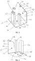
- the drawings show a construction assembly 10 comprising a construction article 12 and a closure member 14.
- the construction assembly is usable in the construction of a building 16 as diagrammatically shown in Fig. 3 and other figures.
- the building 16 has a concrete frame 18 with a plurality of columns 20.
- Cross members (not shown) extending between the columns 20 are provided, which cross members would generally comprise pre cast floor slabs.
- a plurality of concrete floor slabs 22 are provided extending between the columns 20, which slabs 22 will be formed in situ.
- a plurality of panels in the form of facades 24 extending between the columns 20.
- the facades may provide windows 26 and/or doors 28 as illustrated.
- Fixings 30 are provided to mount the facades 24 to the floor slabs 22 and to provide restraint and load bearing of the facades 24.
- each floor slab 22 adjacent respective columns 20 for mounting each facade 24, but different mounting arrangements can be provided as required.
- Each construction article 12 comprises a base member 32 in the form of a plate, with a side member 34 also in the form of a plate, extending perpendicularly from one edge of the base member 32.
- the base member 32 is square and has a central cruciform opening 36 to permit correct location of the construction article 12.
- the cruciform opening 36 can be aligned with an appropriate grid or markings.
- a mounting hole 38 of a size to permit a nail to pass through, is provided adjacent each corner of the base member 32.
- Notches 40 are provided on the three side edges of the base member 32 which do not meet with the side member 34, and the notches 40 are provided centrally to enable the centre of the base member 32 to be correctly aligned.
- Three rectangular cross section hollow tubular upstanding elongate members 42 are provided upstanding from the base member 32, one 44 centrally towards the edge of the base member 32 away from the side member 34, and the other two 46 either side of the cruciform opening 36.
- Each of the elongate members 42 is aligned with a longer direction parallel to the side member, and as shown the one elongate member 44 extends for a greater distance in the longer direction than the other elongate members 46.
- Corresponding openings 48 are provided through the base member 32 such that the elongate members 42 define open hollow channels.
- the side member 34 is provided with a similar central opening 50, mounting holes 52 and notches 54.
- Two rectangular recesses 56 are formed in the top edge of the base member towards each end thereof by a cut out portion being bent downwardly to define a flange 58 with a through mounting hole 60.
- a similar flange 62 is provided on the inner side of the one elongate member 44 spaced from the top thereof to provide three equal height mounting flanges 58, 62.
- the closure member 14 comprises a profiled piece of constant thickness wood, with a first transverse part 64 of a size to fully cover the top of the one elongate member 44 and extend laterally therebeyond on each side.
- a web 66 extends from the first part 64 with a hole 68 there trough to locate a screw to engage in the hole in the flange 62 on the one elongate member 42.
- the web 66 connects to a second longer cross part 70 which is of a size and location to extend between, and a little beyond each of the two other elongate members 46 and close same.
- Two longer webs 72 extend from the second cross part 70 towards ends thereof so as to when located on the construction article 12, locate on the flanges extending from the side member. Again holes are provided towards the end of the longer webs to permit mounting to the flanges 58 extending from the side member 34.
- Fig. 5 shows the closure member 14 mounted on the construction article 12.
- a floor slab 22 can be formed as follows.
- a defined space is provided by appropriate formwork 73 which may for instance be plywood or other wood.
- a side edge 74 to the formwork 73 is provided which will define the front edge of the floor slab 22.
- Two construction assemblies 10 are mounted to the formwork 73 in required positions adjacent respective columns 20, with the side members 34 engageable against the side edge 74 and being mounted thereto by nails passing through the holes 52.
- the base member 32 is also mounted to the respective part of the formwork 73 by nails passing through the respective holes 38.
- the closure member 14 is mounted on the construction article 12.
- Reinforcement in the form of a framework 76 of steel bars is located in the space defined by the formwork 73, as shown in Figs. 6 and 7 . As the construction assemblies 10 are located prior to location of the reinforcement framework 76, the reinforcement will not interfere with the construction articles 12 and particularly the elongate members 44, 46. Concrete is then poured into the space defined by the formwork 73 and allowed to set.
- the formwork 73 can then be removed to provide the arrangement shown in Figs. 9 and 10 .
- the opening 50 on the side member provides a data marking, which could for instance be detected by a theodolite or otherwise to provide an indication of the required positioning of fixings on cladding or otherwise.
- the closure member 14 can now be removed from the concrete, and the closure member 14 converges gently downwardly in use to facilitate its removal. Removal of the closure member 14 leaves a profiled void 78 in the surface of the top of the floor slab 22, which void 78 connects to the three openings extending through the floor slab 22, defined by the elongate members 44, 46.
- a fixing arrangement 80 can now be mounted to each of the construction assemblies 10.
- the fixing arrangement 80 is located against an L-shape protection member 82 to prevent the fixing arrangement 80 damaging the edge of the floor slab 22, or vice versa.
- the fixing arrangement 80 includes a longitudinal member 84 with a through hole 86, which hole 86 is locatable over the opening defined by the one elongate member 42.
- the distance of the opening defined by the one elongate member 42 to the edge of the floor slab 22 is defined by the construction article 12. As the opening defined by the one elongate member 42 is transversely elongate, this permits some lateral tolerence in mounting.
- An appropriate fastening comprising for instance a length of threaded bar and appropriate nuts or other fastenings can extend through the opening defined by the one elongate member 42 to mount the longitudinal member 84 to the construction assembly 10.
- the fixing arrangement 80 also includes a transverse member 88 with two mounting holes 90 which can be similarly mounted to the openings provided by the two elongate members 46. Extending downwardly from the end of the longitudinal member 82 by the edge of the floor slab 22 is a mounting configuration 94 for fixing to a facade 24 to bear the weight of the facade 24.
- an adjustable restraining part 96 with a body 98 and an adjustable elongate member 100 extending therefrom to provide restraining mounting of the facade 24, to provide correct positioning of the facade 24 relative to the frame 18.
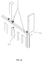
- Fig. 16 shows a facade 24 being lifted into position to enable connection to the mounting configurations 94.
- the construction assembly which permits ready and accurate mounting of facades to floor slabs.
- the construction assembly is formed so as to provide the required correct spacing of the various components and ensures that the openings provided by the elongate member are correctly aligned relative to each other and also the edge of the floor slab.
- significantly less input is required than with previous systems by persons involved in the building construction. This reduces the amount of assembly work required, and also the chances of incorrect mounting which otherwise could lead to significant delays and costs during building construction.
- such assemblies can be formed to be bespoke for particular situations and fittings. Also providing the target on the construction article means that once fitted, the assemblies can be accurately located for instance by a survey or otherwise to ensure that the facades will fit correctly when brought into place.
- the depth of mounting, and also the mounting distance from the edge of the floor slab are fixed, but a certain amount of lateral tolerence is provided to ensure that usual tolerences can be accounted for.
- the top of the closure member will be substantially flush with the top surface of the floor slab. This means that the construction assembly does not hinder operations or cause an obstruction, and this also means that damage thereto in use is unlikely.
- the through holes in the floor slabs 22 mean that a single bolt 102 can extend wholly therethrough, with nuts 104 or other mountings provided at each end.
- fixing arrangements can be mounted to the underside of the floor slabs.
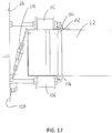
- a fixing arrangement 106 can be mounted to the underside of a floor slab 22 to restrain a hung facade 108, i.e. retain the facade 108 in a required position.
- a fixing arrangement 110 mounted to the top of the floor slab 22 can hang the façade 108, and a further fixing arrangement 112 mounted to the top of the floor slab 22 can also restrain a facade 114 hung from a higher floor slab.
- the above example describes floor slabs being cast in situ. At least some of the floor slabs may though be pre cast off site, with the construction assemblies again incorporated in the floor slabs during casting.
- the floor slabs may have 'downstands' or 'upstands', i.e. downwardly or upwardly extending areas at their edges of increased depth, and the construction assemblies could be provided at such areas.
- Construction assemblies according to the invention could be mounted to beams rather than floor slabs, as and when required.
- the construction assemblies can also be used in temporary engineering activities during construction of a building.
- the assemblies may be used to mount edge protection such as hand rails or screens.
- the assemblies can also be used to mount items such as hoist ties, protection fan assemblies, external access tie positions, and temporary running lines for workers to clip to when for instance mounting other facade elements such as glazing.
- the assembly may be bespoke for particular situations, and this may require a different number and/or positioning of openings and hence elongate members. Whilst a hole is provided in the side member of the construction article, a different marking or target could be used, which could for instance be adhered to the construction article.
- the closure member may take a different form, and could be differently mounted to the construction article.
- the closure member could for instance be made of a plastics material or other material, and may include formations which provide for mounting to the construction article.
- a handle or other formation could be provided on the closure member to facilitate removal thereof once the floor slab is formed.
- the shape of the openings could be different.
- the construction article is made from steel which may be stainless steel or galvanised steel, but different materials could be used.
- the construction article and/or closure member may take a different form and could for instance provide a recess in the edge of the floor slab to receive part of a fixing.
Landscapes
- Engineering & Computer Science (AREA)
- Architecture (AREA)
- Civil Engineering (AREA)
- Structural Engineering (AREA)
- Physics & Mathematics (AREA)
- Electromagnetism (AREA)
- Mechanical Engineering (AREA)
- Manufacturing & Machinery (AREA)
- Chemical & Material Sciences (AREA)
- Ceramic Engineering (AREA)
- Forms Removed On Construction Sites Or Auxiliary Members Thereof (AREA)
- Joining Of Building Structures In Genera (AREA)
Claims (15)
- Verfahren zum Formen eines Bauteils aus einem aushärtbaren Material, wobei das Verfahren das Ausbilden eines definierten Raums zur Aufnahme eines aushärtbaren Materials, das Anordnen einer Konstruktionsanordnung (10), wobei die Konstruktionsanordnung einen in dem definierten Raum anordenbaren Konstruktionsgegenstand (12) aufweist, um das aushärtbare Material aufzunehmen, sodass, wenn das aushärtbare Material aushärtet, um das Bauteil zu bilden, der Konstruktionsgegenstand einen Teil des Bauteils bildet, wobei der Konstruktionsgegenstand ein Basiselement (32) aufweist, das so anordenbar ist, dass es sich über einen untersten Teil des definierten Raums erstreckt, ein Seitenelement (34), das sich von einer Kante des Basiselements aus erstrecken kann, die sich entlang einer Seitenkante (74) des definierten Raums erstrecken kann, ein hohles, längliches Element (42), das von dem Basiselement hochsteht und von dem Seitenelement beabstandet ist, um eine längliche Durchgangsöffnung mit offenem Ende in dem Bauteil zu bilden, sobald das aushärtbare Material ausgehärtet ist, und wobei die Konstruktionsanordnung auch ein Verschlusselement (14) aufweist, das selektiv über ein offenes Ende des von dem Basiselement beabstandeten hohlen länglichen Elements angeordnet werden kann, um das hohle längliche Element zu schließen bis das aushärtbare Material ausgehärtet ist, wobei die kombinierte Höhe des hohlen länglichen Elements und des Verschlusselements mindestens gleich der Höhe des definierten Raums ist, wenn diese
von dem Ende des hohlen länglichen Elements angeordnet sind, wobei das Verfahren ferner das Anordnen des Verschlusselements an dem Konstruktionsgegenstand, das Anordnen von Verstärkungselementen in dem definierten Raum, das Füllen des definierten Raums mit aushärtbarem Material bis zur Höhe des definierten Raums, aber nicht darüber hinaus, und sobald das Material ausgehärtet ist, Entfernen des Verschlusselements von dem Konstruktionsgegenstand aufweist. - Verfahren nach Anspruch 1, dadurch gekennzeichnet, dass die kombinierte Höhe des hohlen länglichen Elements und des Verschlusselementes im Wesentlichen gleich zu der Höhe des definierten Raumes ist, wenn das Verschlusselement auf dem besagten Ende des hohlen länglichen Elements angeordnet ist.
- Verfahren nach Anspruch 1 oder 2, dadurch gekennzeichnet, dass eine Vielzahl an hohlen länglichen Elementen vergesehen werden, die sich von dem Basiselement aus erstrecken und zueinander beabstandet sind.
- Verfahren nach einem der vorhergehenden Ansprüche, dadurch gekennzeichnet, dass eine oder mehrere Ausformungen auf dem Konstruktionsgegenstand vorgesehen sind, um das Verschlusselement auf dem Konstruktionsgegenstand in Position zu halten, das das Ende des hohlen länglichen Elements oder der hohlen länglichen Elemente verschließt, wobei die Ausformungen Laschen aufweisen und die Laschen eine Öffnung aufweisen, damit sich ein Befestigungsmittel durch sie hindurch erstrecken kann, um mit dem Verschlusselement in Eingriff zu kommen.
- Verfahren nach einem der vorhergehenden Ansprüche, dadurch gekennzeichnet, dass das Basiselement und das Seitenelement senkrecht zueinander verlaufen.
- Verfahren nach einem der vorhergehenden Ansprüche, dadurch gekennzeichnet, dass ein Ziel oder ein anderes Symbol, eine Markierung oder eine Ausformung auf der Außenseite des Seitenelements vorgesehen ist, um die Erfassung der Lage des Konstruktionsgegenstandes zu ermöglichen, und das Ziel oder ein anderes Symbol, eine Markierung oder eine Ausformung mittig am Seitenteil angebracht wird.
- Verfahren nach einem der vorhergehenden Ansprüche, dadurch gekennzeichnet, dass eine Ausformung am Basiselement vorgesehen ist, um die korrekte Positionierung des Konstruktionsgegenstandes zu erleichtern, wobei die Ausformung eine Öffnung (36) aufweist, die ein kreuzförmiges Profil hat und mittig in dem Basiselement vorgesehen ist.
- Verfahren nach einem der vorhergehenden Ansprüche, dadurch gekennzeichnet, dass Öffnungen an dem Basiselement und/oder Seitenelement vorgesehen sind, um eine Befestigung des Konstruktionsgegenstandes an einer den definierten Raum bildenden Schalung zu erleichtern.
- Verfahren nach einem der vorhergehenden Ansprüche, dadurch gekennzeichnet, dass Markierungen in Seitenkanten des Basiselements und/oder des Seitenelements vorgesehen sind, um eine korrekte Positionierung des Konstruktionsgegenstandes zu erleichtern, wobei die Markierungen in der Form von Erhebungen (40) ausgebildet sind, und die Markierungen auf halbem Weg der jeweiligen Seitenkante des Basiselements und/oder des Seitenelements vorgesehen sind.
- Verfahren nach einem der vorhergehenden Ansprüche, dadurch gekennzeichnet, dass das Verschlusselement zu einer Seite hin konvergiert, die an dem offenen Ende des hohlen länglichen Elements anliegt.
- Verfahren nach einem der vorhergehenden Ansprüche, dadurch gekennzeichnet, dass das Verschlusselement ein profiliertes Element aufweist, dass das Ende des einen oder der mehreren hohlen länglichen Elemente, die von dem Basiselement hochstehen, verschließt, wobei das Verschlusselement so profiliert ist, dass es sich von dem Seitenelement erstreckt, um das Ende des einen oder der mehreren hohlen länglichen Elemente zu schließen, und das Verschlusselement sich von dem Seitenelement an zwei beabstandeten Stellen erstreckt.
- Verfahren nach einem der vorhergehenden Ansprüche, dadurch gekennzeichnet, dass das Verschlusselement eine im Wesentlichen konstante Dicke aufweist und aus Holz oder einem Kunststoff hergestellt ist.
- Verfahren nach einem der vorhergehenden Ansprüche, dadurch gekennzeichnet, dass der Konstruktionsgegenstand aus Metall, rostfreiem Stahl oder galvanisiertem Stahl hergestellt ist.
- Verfahren nach einem der vorhergehenden Ansprüche, dadurch gekennzeichnet, dass der definierte Raum durch ein Rahmen gebildet wird und der Konstruktionsgegenstand vor der Zuführung von aushärtenbarem Material in den definierten Raum an dem Rahmen befestigt wird.
- Verfahren zum Errichten eines Gebäudes (16), dadurch gekennzeichnet, dass das Verfahren das Ausbilden einer Bodenplattenkomponente durch ein Verfahren nach einem der vorhergehenden Ansprüche mit mindestens zwei Konstruktionsgegenständen (12) in der Bodenplatte, das Anbringen einer Befestigung (30) an jedem Konstruktionsgegenstand, und das Anbringen einer Verkleidung an der Befestigung aufweist.
Applications Claiming Priority (2)
| Application Number | Priority Date | Filing Date | Title |
|---|---|---|---|
| GB1606084.0A GB2549275B (en) | 2016-04-11 | 2016-04-11 | Construction assembly |
| PCT/GB2017/050823 WO2017178786A1 (en) | 2016-04-11 | 2017-03-29 | Construction assembly |
Publications (2)
| Publication Number | Publication Date |
|---|---|
| EP3443171A1 EP3443171A1 (de) | 2019-02-20 |
| EP3443171B1 true EP3443171B1 (de) | 2021-11-17 |
Family
ID=58464596
Family Applications (1)
| Application Number | Title | Priority Date | Filing Date |
|---|---|---|---|
| EP17715262.6A Active EP3443171B1 (de) | 2016-04-11 | 2017-03-29 | Konstruktionsanordnung |
Country Status (4)
| Country | Link |
|---|---|
| US (1) | US10829945B2 (de) |
| EP (1) | EP3443171B1 (de) |
| GB (1) | GB2549275B (de) |
| WO (1) | WO2017178786A1 (de) |
Families Citing this family (6)
| Publication number | Priority date | Publication date | Assignee | Title |
|---|---|---|---|---|
| GB2549275B (en) * | 2016-04-11 | 2018-05-09 | Tectonic Facades Ltd | Construction assembly |
| US12110678B2 (en) * | 2020-07-09 | 2024-10-08 | Meadow Burke, Llc | Reinforcement for a connector in a precast concrete panel |
| US20230417072A1 (en) * | 2022-06-27 | 2023-12-28 | JMR Technologies | Thermally Insulated Tilt-Up Wall Lift and Brace Assemblies |
| US12421713B2 (en) * | 2023-06-08 | 2025-09-23 | Unistress Corp. | Reinforcement apparatus for concrete |
| US20250347107A1 (en) * | 2024-05-08 | 2025-11-13 | 3Jr, Llc | Systems and methods for building elevated structures |
| CN119928063B (zh) * | 2025-04-08 | 2025-06-03 | 中铁四局集团有限公司 | 一种大体积竖井管片钢筋笼振捣抗浮结构及应用方法 |
Family Cites Families (24)
| Publication number | Priority date | Publication date | Assignee | Title |
|---|---|---|---|---|
| US1260147A (en) * | 1917-09-20 | 1918-03-19 | Theodore Cornuelle | Mold for the manufacture of concrete blocks. |
| FR1422176A (fr) | 1964-10-22 | 1965-12-24 | Applic Des Tech Modernes Au Ba | Perfectionnements apportés au montage et à la fixation de panneaux de façade ou éléments analogues |
| US3803784A (en) * | 1971-06-25 | 1974-04-16 | O Becker | Composite wall element for thermal and acoustic insulation |
| AT313538B (de) * | 1971-08-17 | 1974-02-25 | Katzenberger Helmut | Vorrichtung zur Befestigung von Verkleidungsplatten an Außenwänden |
| FR2509773A1 (fr) * | 1981-07-16 | 1983-01-21 | Ing Coordination Const | Dispositif destine a permettre l'appui d'un plancher sur un mur, et procede de construction mettant en oeuvre celui-ci |
| DE3844211A1 (de) * | 1988-12-29 | 1990-07-05 | Hoechst Ag | Neue insulinderivate, verfahren zu deren herstellung, ihre verwendung und eine sie enthaltende pharmazeutische zubereitung |
| US5937609A (en) * | 1995-11-27 | 1999-08-17 | Roth; Steven A. | Concrete insert to support anchor bolt |
| DE29611201U1 (de) * | 1996-06-27 | 1996-09-05 | Hebel Ag, 82275 Emmering | Befestigungselement zur Befestigung von vorgehängten Fassaden an Wänden, insbesondere aus Porenbetonelementen |
| CN1584262A (zh) * | 2004-06-03 | 2005-02-23 | 奇美实业股份有限公司 | 混凝土楼板预留开孔的成型装置及其施工方法(二) |
| US20070079565A1 (en) | 2005-07-25 | 2007-04-12 | Bahram Bahramian | Light weight sandwich panels |
| US7681366B2 (en) | 2007-03-15 | 2010-03-23 | Permasteelisa Cladding Technologies, L.P. | Curtain wall anchor system |
| US8505267B2 (en) * | 2007-07-13 | 2013-08-13 | Juan Jose Martin Hernandez | Holder for being positioned in floating floor slabs and installation system thereof |
| FI20115154A7 (fi) * | 2011-02-17 | 2012-08-18 | Peikko Group Oy | Kiinnityslevyn vetovahviste betonielementissä |
| US8915038B1 (en) * | 2013-05-30 | 2014-12-23 | John D. Crane | Dynamic concrete form |
| US9617746B1 (en) * | 2014-01-14 | 2017-04-11 | Maestro International, Llc | Forged lift anchor for precast portland cement concrete shapes |
| DE202014003376U1 (de) * | 2014-04-23 | 2014-04-30 | Halfen Gmbh | Konsolanker |
| AT516415B1 (de) * | 2014-10-15 | 2016-07-15 | KAPPA Filter Systems GmbH | Verbindungsvorrichtung zur mechanischen Kopplung von Betonplatten, sowie damit aufgebaute Betonwand |
| US9896840B2 (en) * | 2016-02-23 | 2018-02-20 | Advanced Building Systems, Inc. | Curtain wall mullion anchoring system |
| US9683367B1 (en) * | 2016-02-23 | 2017-06-20 | Advanced Building Systems, Inc. | Curtain wall mullion anchoring system |
| GB2549275B (en) * | 2016-04-11 | 2018-05-09 | Tectonic Facades Ltd | Construction assembly |
| US10370845B2 (en) * | 2017-03-08 | 2019-08-06 | Maestro International, Llc | Rotating pin locking connector |
| CA3103889C (en) * | 2017-05-31 | 2023-05-02 | Meadow Burke, Llc | Connector for precast concrete structures |
| US10731330B2 (en) * | 2017-10-24 | 2020-08-04 | Unistress Corp. | Corbel |
| CH714813A2 (de) * | 2018-03-20 | 2019-09-30 | Albanese Pino | System zur temporären Befestigung einer Kletterkonsole, Konsole und eine Verankerungsdose. |
-
2016
- 2016-04-11 GB GB1606084.0A patent/GB2549275B/en active Active
-
2017
- 2017-03-29 WO PCT/GB2017/050823 patent/WO2017178786A1/en not_active Ceased
- 2017-03-29 EP EP17715262.6A patent/EP3443171B1/de active Active
- 2017-03-29 US US16/093,136 patent/US10829945B2/en active Active
Non-Patent Citations (1)
| Title |
|---|
| None * |
Also Published As
| Publication number | Publication date |
|---|---|
| WO2017178786A1 (en) | 2017-10-19 |
| US10829945B2 (en) | 2020-11-10 |
| GB2549275A (en) | 2017-10-18 |
| GB2549275B (en) | 2018-05-09 |
| EP3443171A1 (de) | 2019-02-20 |
| US20190309533A1 (en) | 2019-10-10 |
Similar Documents
| Publication | Publication Date | Title |
|---|---|---|
| EP3443171B1 (de) | Konstruktionsanordnung | |
| US8844224B2 (en) | Utility dowel bracket | |
| US12065844B2 (en) | Large area slab panel formwork system | |
| US3810339A (en) | Method and apparatus for forming construction element locating and mounting voids in a poured concrete structure | |
| CN104956011A (zh) | 预埋件附接系统 | |
| US10947746B2 (en) | Configurable steel form system for fabricating precast panels | |
| EP1123443A1 (de) | Methode zum herstellen eines plattenbodens und ein plattenboden | |
| EP2084347B1 (de) | Seitenschalungsbefestigungssystem | |
| CN107075860A (zh) | 模板布置 | |
| KR101363489B1 (ko) | 방음벽 기초 | |
| US20100005736A1 (en) | Method of concrete building construction and adjustable brace system therefor | |
| GB2522887A (en) | Shuttering system | |
| AU2019100345A4 (en) | Formwork element and formwork system | |
| DE7714716U1 (de) | Anker fuer das abfangen von abstand zur tragenden wandung belassenden bauelementen | |
| GB2522886A (en) | Shuttering system | |
| WO2021110228A1 (en) | Modular mould system | |
| US20250179792A1 (en) | Riser assembly | |
| SE512789C2 (sv) | Sätt att bygga vertikala väggpartier samt fästelement för utnyttjande vid sättet | |
| EP3341171B1 (de) | Ständerplatte zur formung einer ständeranordnung | |
| US10577794B2 (en) | Wall construction | |
| DE9400637U1 (de) | Deckenabschalstein mit integrierter Wärmedämmung | |
| KR101636407B1 (ko) | 벽돌 현가 시공용 매립브라켓 어셈블리 및 이를 이용한 조적방법 | |
| EP0290831B1 (de) | Bewehrungslagen-Abstützvorrichtung | |
| KR20110006970U (ko) | 목판과 스틸판으로 이루어진 거푸집 | |
| EP3760813A1 (de) | Abstandshälter für wandschalungen |
Legal Events
| Date | Code | Title | Description |
|---|---|---|---|
| STAA | Information on the status of an ep patent application or granted ep patent |
Free format text: STATUS: UNKNOWN |
|
| STAA | Information on the status of an ep patent application or granted ep patent |
Free format text: STATUS: THE INTERNATIONAL PUBLICATION HAS BEEN MADE |
|
| PUAI | Public reference made under article 153(3) epc to a published international application that has entered the european phase |
Free format text: ORIGINAL CODE: 0009012 |
|
| STAA | Information on the status of an ep patent application or granted ep patent |
Free format text: STATUS: REQUEST FOR EXAMINATION WAS MADE |
|
| 17P | Request for examination filed |
Effective date: 20181018 |
|
| AK | Designated contracting states |
Kind code of ref document: A1 Designated state(s): AL AT BE BG CH CY CZ DE DK EE ES FI FR GB GR HR HU IE IS IT LI LT LU LV MC MK MT NL NO PL PT RO RS SE SI SK SM TR |
|
| AX | Request for extension of the european patent |
Extension state: BA ME |
|
| DAV | Request for validation of the european patent (deleted) | ||
| DAX | Request for extension of the european patent (deleted) | ||
| STAA | Information on the status of an ep patent application or granted ep patent |
Free format text: STATUS: EXAMINATION IS IN PROGRESS |
|
| 17Q | First examination report despatched |
Effective date: 20191112 |
|
| GRAP | Despatch of communication of intention to grant a patent |
Free format text: ORIGINAL CODE: EPIDOSNIGR1 |
|
| STAA | Information on the status of an ep patent application or granted ep patent |
Free format text: STATUS: GRANT OF PATENT IS INTENDED |
|
| INTG | Intention to grant announced |
Effective date: 20210610 |
|
| GRAS | Grant fee paid |
Free format text: ORIGINAL CODE: EPIDOSNIGR3 |
|
| GRAA | (expected) grant |
Free format text: ORIGINAL CODE: 0009210 |
|
| STAA | Information on the status of an ep patent application or granted ep patent |
Free format text: STATUS: THE PATENT HAS BEEN GRANTED |
|
| AK | Designated contracting states |
Kind code of ref document: B1 Designated state(s): AL AT BE BG CH CY CZ DE DK EE ES FI FR GR HR HU IE IS IT LI LT LU LV MC MK MT NL NO PL PT RO RS SE SI SK SM TR |
|
| RBV | Designated contracting states (corrected) |
Designated state(s): AL AT BE BG CH CY CZ DE DK EE ES FI FR GR HR HU IE IS IT LI LT LU LV MC MK MT NL NO PL PT RO RS SE SI SK SM TR |
|
| REG | Reference to a national code |
Ref country code: DE Ref legal event code: R096 Ref document number: 602017049406 Country of ref document: DE |
|
| REG | Reference to a national code |
Ref country code: IE Ref legal event code: FG4D |
|
| REG | Reference to a national code |
Ref country code: AT Ref legal event code: REF Ref document number: 1448169 Country of ref document: AT Kind code of ref document: T Effective date: 20211215 |
|
| REG | Reference to a national code |
Ref country code: LT Ref legal event code: MG9D |
|
| REG | Reference to a national code |
Ref country code: NL Ref legal event code: MP Effective date: 20211117 |
|
| REG | Reference to a national code |
Ref country code: AT Ref legal event code: MK05 Ref document number: 1448169 Country of ref document: AT Kind code of ref document: T Effective date: 20211117 |
|
| PG25 | Lapsed in a contracting state [announced via postgrant information from national office to epo] |
Ref country code: RS Free format text: LAPSE BECAUSE OF FAILURE TO SUBMIT A TRANSLATION OF THE DESCRIPTION OR TO PAY THE FEE WITHIN THE PRESCRIBED TIME-LIMIT Effective date: 20211117 Ref country code: LT Free format text: LAPSE BECAUSE OF FAILURE TO SUBMIT A TRANSLATION OF THE DESCRIPTION OR TO PAY THE FEE WITHIN THE PRESCRIBED TIME-LIMIT Effective date: 20211117 Ref country code: FI Free format text: LAPSE BECAUSE OF FAILURE TO SUBMIT A TRANSLATION OF THE DESCRIPTION OR TO PAY THE FEE WITHIN THE PRESCRIBED TIME-LIMIT Effective date: 20211117 Ref country code: BG Free format text: LAPSE BECAUSE OF FAILURE TO SUBMIT A TRANSLATION OF THE DESCRIPTION OR TO PAY THE FEE WITHIN THE PRESCRIBED TIME-LIMIT Effective date: 20220217 Ref country code: AT Free format text: LAPSE BECAUSE OF FAILURE TO SUBMIT A TRANSLATION OF THE DESCRIPTION OR TO PAY THE FEE WITHIN THE PRESCRIBED TIME-LIMIT Effective date: 20211117 |
|
| PG25 | Lapsed in a contracting state [announced via postgrant information from national office to epo] |
Ref country code: IS Free format text: LAPSE BECAUSE OF FAILURE TO SUBMIT A TRANSLATION OF THE DESCRIPTION OR TO PAY THE FEE WITHIN THE PRESCRIBED TIME-LIMIT Effective date: 20220317 Ref country code: SE Free format text: LAPSE BECAUSE OF FAILURE TO SUBMIT A TRANSLATION OF THE DESCRIPTION OR TO PAY THE FEE WITHIN THE PRESCRIBED TIME-LIMIT Effective date: 20211117 Ref country code: PT Free format text: LAPSE BECAUSE OF FAILURE TO SUBMIT A TRANSLATION OF THE DESCRIPTION OR TO PAY THE FEE WITHIN THE PRESCRIBED TIME-LIMIT Effective date: 20220317 Ref country code: PL Free format text: LAPSE BECAUSE OF FAILURE TO SUBMIT A TRANSLATION OF THE DESCRIPTION OR TO PAY THE FEE WITHIN THE PRESCRIBED TIME-LIMIT Effective date: 20211117 Ref country code: NO Free format text: LAPSE BECAUSE OF FAILURE TO SUBMIT A TRANSLATION OF THE DESCRIPTION OR TO PAY THE FEE WITHIN THE PRESCRIBED TIME-LIMIT Effective date: 20220217 Ref country code: NL Free format text: LAPSE BECAUSE OF FAILURE TO SUBMIT A TRANSLATION OF THE DESCRIPTION OR TO PAY THE FEE WITHIN THE PRESCRIBED TIME-LIMIT Effective date: 20211117 Ref country code: LV Free format text: LAPSE BECAUSE OF FAILURE TO SUBMIT A TRANSLATION OF THE DESCRIPTION OR TO PAY THE FEE WITHIN THE PRESCRIBED TIME-LIMIT Effective date: 20211117 Ref country code: HR Free format text: LAPSE BECAUSE OF FAILURE TO SUBMIT A TRANSLATION OF THE DESCRIPTION OR TO PAY THE FEE WITHIN THE PRESCRIBED TIME-LIMIT Effective date: 20211117 Ref country code: GR Free format text: LAPSE BECAUSE OF FAILURE TO SUBMIT A TRANSLATION OF THE DESCRIPTION OR TO PAY THE FEE WITHIN THE PRESCRIBED TIME-LIMIT Effective date: 20220218 Ref country code: ES Free format text: LAPSE BECAUSE OF FAILURE TO SUBMIT A TRANSLATION OF THE DESCRIPTION OR TO PAY THE FEE WITHIN THE PRESCRIBED TIME-LIMIT Effective date: 20211117 |
|
| PG25 | Lapsed in a contracting state [announced via postgrant information from national office to epo] |
Ref country code: SM Free format text: LAPSE BECAUSE OF FAILURE TO SUBMIT A TRANSLATION OF THE DESCRIPTION OR TO PAY THE FEE WITHIN THE PRESCRIBED TIME-LIMIT Effective date: 20211117 Ref country code: SK Free format text: LAPSE BECAUSE OF FAILURE TO SUBMIT A TRANSLATION OF THE DESCRIPTION OR TO PAY THE FEE WITHIN THE PRESCRIBED TIME-LIMIT Effective date: 20211117 Ref country code: RO Free format text: LAPSE BECAUSE OF FAILURE TO SUBMIT A TRANSLATION OF THE DESCRIPTION OR TO PAY THE FEE WITHIN THE PRESCRIBED TIME-LIMIT Effective date: 20211117 Ref country code: EE Free format text: LAPSE BECAUSE OF FAILURE TO SUBMIT A TRANSLATION OF THE DESCRIPTION OR TO PAY THE FEE WITHIN THE PRESCRIBED TIME-LIMIT Effective date: 20211117 Ref country code: DK Free format text: LAPSE BECAUSE OF FAILURE TO SUBMIT A TRANSLATION OF THE DESCRIPTION OR TO PAY THE FEE WITHIN THE PRESCRIBED TIME-LIMIT Effective date: 20211117 Ref country code: CZ Free format text: LAPSE BECAUSE OF FAILURE TO SUBMIT A TRANSLATION OF THE DESCRIPTION OR TO PAY THE FEE WITHIN THE PRESCRIBED TIME-LIMIT Effective date: 20211117 |
|
| REG | Reference to a national code |
Ref country code: DE Ref legal event code: R097 Ref document number: 602017049406 Country of ref document: DE |
|
| PLBE | No opposition filed within time limit |
Free format text: ORIGINAL CODE: 0009261 |
|
| STAA | Information on the status of an ep patent application or granted ep patent |
Free format text: STATUS: NO OPPOSITION FILED WITHIN TIME LIMIT |
|
| 26N | No opposition filed |
Effective date: 20220818 |
|
| PG25 | Lapsed in a contracting state [announced via postgrant information from national office to epo] |
Ref country code: MC Free format text: LAPSE BECAUSE OF FAILURE TO SUBMIT A TRANSLATION OF THE DESCRIPTION OR TO PAY THE FEE WITHIN THE PRESCRIBED TIME-LIMIT Effective date: 20211117 Ref country code: AL Free format text: LAPSE BECAUSE OF FAILURE TO SUBMIT A TRANSLATION OF THE DESCRIPTION OR TO PAY THE FEE WITHIN THE PRESCRIBED TIME-LIMIT Effective date: 20211117 |
|
| REG | Reference to a national code |
Ref country code: CH Ref legal event code: PL |
|
| PG25 | Lapsed in a contracting state [announced via postgrant information from national office to epo] |
Ref country code: SI Free format text: LAPSE BECAUSE OF FAILURE TO SUBMIT A TRANSLATION OF THE DESCRIPTION OR TO PAY THE FEE WITHIN THE PRESCRIBED TIME-LIMIT Effective date: 20211117 |
|
| PG25 | Lapsed in a contracting state [announced via postgrant information from national office to epo] |
Ref country code: LU Free format text: LAPSE BECAUSE OF NON-PAYMENT OF DUE FEES Effective date: 20220329 Ref country code: LI Free format text: LAPSE BECAUSE OF NON-PAYMENT OF DUE FEES Effective date: 20220331 Ref country code: CH Free format text: LAPSE BECAUSE OF NON-PAYMENT OF DUE FEES Effective date: 20220331 |
|
| PG25 | Lapsed in a contracting state [announced via postgrant information from national office to epo] |
Ref country code: IT Free format text: LAPSE BECAUSE OF FAILURE TO SUBMIT A TRANSLATION OF THE DESCRIPTION OR TO PAY THE FEE WITHIN THE PRESCRIBED TIME-LIMIT Effective date: 20211117 |
|
| PG25 | Lapsed in a contracting state [announced via postgrant information from national office to epo] |
Ref country code: HU Free format text: LAPSE BECAUSE OF FAILURE TO SUBMIT A TRANSLATION OF THE DESCRIPTION OR TO PAY THE FEE WITHIN THE PRESCRIBED TIME-LIMIT; INVALID AB INITIO Effective date: 20170329 |
|
| PG25 | Lapsed in a contracting state [announced via postgrant information from national office to epo] |
Ref country code: MK Free format text: LAPSE BECAUSE OF FAILURE TO SUBMIT A TRANSLATION OF THE DESCRIPTION OR TO PAY THE FEE WITHIN THE PRESCRIBED TIME-LIMIT Effective date: 20211117 Ref country code: CY Free format text: LAPSE BECAUSE OF FAILURE TO SUBMIT A TRANSLATION OF THE DESCRIPTION OR TO PAY THE FEE WITHIN THE PRESCRIBED TIME-LIMIT Effective date: 20211117 |
|
| PG25 | Lapsed in a contracting state [announced via postgrant information from national office to epo] |
Ref country code: TR Free format text: LAPSE BECAUSE OF FAILURE TO SUBMIT A TRANSLATION OF THE DESCRIPTION OR TO PAY THE FEE WITHIN THE PRESCRIBED TIME-LIMIT Effective date: 20211117 |
|
| PG25 | Lapsed in a contracting state [announced via postgrant information from national office to epo] |
Ref country code: MT Free format text: LAPSE BECAUSE OF FAILURE TO SUBMIT A TRANSLATION OF THE DESCRIPTION OR TO PAY THE FEE WITHIN THE PRESCRIBED TIME-LIMIT Effective date: 20211117 |
|
| PGFP | Annual fee paid to national office [announced via postgrant information from national office to epo] |
Ref country code: DE Payment date: 20260304 Year of fee payment: 10 Ref country code: IE Payment date: 20260226 Year of fee payment: 10 |
|
| PGFP | Annual fee paid to national office [announced via postgrant information from national office to epo] |
Ref country code: BE Payment date: 20260227 Year of fee payment: 10 |
|
| PGFP | Annual fee paid to national office [announced via postgrant information from national office to epo] |
Ref country code: FR Payment date: 20260330 Year of fee payment: 10 |