EP3341992B1 - Dispositif pour cellule électrochimique - Google Patents
Dispositif pour cellule électrochimique Download PDFInfo
- Publication number
- EP3341992B1 EP3341992B1 EP16840880.5A EP16840880A EP3341992B1 EP 3341992 B1 EP3341992 B1 EP 3341992B1 EP 16840880 A EP16840880 A EP 16840880A EP 3341992 B1 EP3341992 B1 EP 3341992B1
- Authority
- EP
- European Patent Office
- Prior art keywords
- layer
- substrate material
- electrodes
- substrate
- hydrophilic areas
- Prior art date
- Legal status (The legal status is an assumption and is not a legal conclusion. Google has not performed a legal analysis and makes no representation as to the accuracy of the status listed.)
- Active
Links
- 239000000758 substrate Substances 0.000 claims description 211
- 239000000463 material Substances 0.000 claims description 139
- 239000007788 liquid Substances 0.000 claims description 67
- 238000007639 printing Methods 0.000 claims description 32
- 230000002209 hydrophobic effect Effects 0.000 claims description 22
- 238000011282 treatment Methods 0.000 claims description 18
- 239000007772 electrode material Substances 0.000 claims description 16
- 238000000034 method Methods 0.000 claims description 15
- 239000004020 conductor Substances 0.000 claims description 12
- 208000008454 Hyperhidrosis Diseases 0.000 claims description 8
- 239000004744 fabric Substances 0.000 claims description 8
- XLYOFNOQVPJJNP-UHFFFAOYSA-N water Substances O XLYOFNOQVPJJNP-UHFFFAOYSA-N 0.000 claims description 8
- 201000010099 disease Diseases 0.000 claims description 5
- 208000037265 diseases, disorders, signs and symptoms Diseases 0.000 claims description 5
- 239000000203 mixture Substances 0.000 claims description 5
- 239000000123 paper Substances 0.000 claims description 5
- 210000004243 sweat Anatomy 0.000 claims description 5
- 201000004384 Alopecia Diseases 0.000 claims description 4
- 208000002193 Pain Diseases 0.000 claims description 4
- 230000017531 blood circulation Effects 0.000 claims description 4
- 239000002537 cosmetic Substances 0.000 claims description 4
- 230000037315 hyperhidrosis Effects 0.000 claims description 4
- 239000004753 textile Substances 0.000 claims description 4
- 210000002700 urine Anatomy 0.000 claims description 4
- 208000034656 Contusions Diseases 0.000 claims description 3
- 229920000544 Gore-Tex Polymers 0.000 claims description 3
- FAPWRFPIFSIZLT-UHFFFAOYSA-M Sodium chloride Chemical compound [Na+].[Cl-] FAPWRFPIFSIZLT-UHFFFAOYSA-M 0.000 claims description 3
- 239000008280 blood Substances 0.000 claims description 3
- 210000004369 blood Anatomy 0.000 claims description 3
- 230000002708 enhancing effect Effects 0.000 claims description 3
- 239000011087 paperboard Substances 0.000 claims description 3
- 239000011780 sodium chloride Substances 0.000 claims description 3
- 230000036642 wellbeing Effects 0.000 claims description 3
- 208000032544 Cicatrix Diseases 0.000 claims description 2
- 229920000742 Cotton Polymers 0.000 claims description 2
- 206010056340 Diabetic ulcer Diseases 0.000 claims description 2
- 208000019695 Migraine disease Diseases 0.000 claims description 2
- 239000004952 Polyamide Substances 0.000 claims description 2
- 229920000297 Rayon Polymers 0.000 claims description 2
- 206010052428 Wound Diseases 0.000 claims description 2
- 208000027418 Wounds and injury Diseases 0.000 claims description 2
- 231100000360 alopecia Toxicity 0.000 claims description 2
- 239000002269 analeptic agent Substances 0.000 claims description 2
- 229940079593 drug Drugs 0.000 claims description 2
- 239000003814 drug Substances 0.000 claims description 2
- 208000024963 hair loss Diseases 0.000 claims description 2
- 230000003676 hair loss Effects 0.000 claims description 2
- 206010027599 migraine Diseases 0.000 claims description 2
- 208000030613 peripheral artery disease Diseases 0.000 claims description 2
- 229920002647 polyamide Polymers 0.000 claims description 2
- 231100000241 scar Toxicity 0.000 claims description 2
- 230000037387 scars Effects 0.000 claims description 2
- SNICXCGAKADSCV-JTQLQIEISA-N (-)-Nicotine Chemical compound CN1CCC[C@H]1C1=CC=CN=C1 SNICXCGAKADSCV-JTQLQIEISA-N 0.000 claims 1
- 229960002715 nicotine Drugs 0.000 claims 1
- SNICXCGAKADSCV-UHFFFAOYSA-N nicotine Natural products CN1CCCC1C1=CC=CN=C1 SNICXCGAKADSCV-UHFFFAOYSA-N 0.000 claims 1
- 239000010410 layer Substances 0.000 description 165
- 239000000243 solution Substances 0.000 description 23
- 239000000523 sample Substances 0.000 description 10
- 230000000694 effects Effects 0.000 description 8
- 238000004519 manufacturing process Methods 0.000 description 8
- 230000008901 benefit Effects 0.000 description 7
- 102000004190 Enzymes Human genes 0.000 description 6
- 108090000790 Enzymes Proteins 0.000 description 6
- 230000004888 barrier function Effects 0.000 description 6
- 229940088598 enzyme Drugs 0.000 description 6
- 239000000446 fuel Substances 0.000 description 6
- 238000006243 chemical reaction Methods 0.000 description 5
- 239000003792 electrolyte Substances 0.000 description 5
- KDLHZDBZIXYQEI-UHFFFAOYSA-N Palladium Chemical compound [Pd] KDLHZDBZIXYQEI-UHFFFAOYSA-N 0.000 description 4
- 239000002551 biofuel Substances 0.000 description 4
- 239000003054 catalyst Substances 0.000 description 4
- 239000002001 electrolyte material Substances 0.000 description 4
- -1 for example Chemical class 0.000 description 4
- 230000004089 microcirculation Effects 0.000 description 4
- 230000003647 oxidation Effects 0.000 description 4
- 238000007254 oxidation reaction Methods 0.000 description 4
- 230000001590 oxidative effect Effects 0.000 description 4
- BASFCYQUMIYNBI-UHFFFAOYSA-N platinum Chemical compound [Pt] BASFCYQUMIYNBI-UHFFFAOYSA-N 0.000 description 4
- 229920000642 polymer Polymers 0.000 description 4
- 230000035900 sweating Effects 0.000 description 4
- 239000010409 thin film Substances 0.000 description 4
- LFQSCWFLJHTTHZ-UHFFFAOYSA-N Ethanol Chemical compound CCO LFQSCWFLJHTTHZ-UHFFFAOYSA-N 0.000 description 3
- KFZMGEQAYNKOFK-UHFFFAOYSA-N Isopropanol Chemical compound CC(C)O KFZMGEQAYNKOFK-UHFFFAOYSA-N 0.000 description 3
- OKKJLVBELUTLKV-UHFFFAOYSA-N Methanol Chemical compound OC OKKJLVBELUTLKV-UHFFFAOYSA-N 0.000 description 3
- BQCADISMDOOEFD-UHFFFAOYSA-N Silver Chemical compound [Ag] BQCADISMDOOEFD-UHFFFAOYSA-N 0.000 description 3
- 230000008569 process Effects 0.000 description 3
- 150000003839 salts Chemical class 0.000 description 3
- 229910052709 silver Inorganic materials 0.000 description 3
- 239000004332 silver Substances 0.000 description 3
- 239000002904 solvent Substances 0.000 description 3
- 239000008096 xylene Substances 0.000 description 3
- NLXLAEXVIDQMFP-UHFFFAOYSA-N Ammonia chloride Chemical compound [NH4+].[Cl-] NLXLAEXVIDQMFP-UHFFFAOYSA-N 0.000 description 2
- CIWBSHSKHKDKBQ-JLAZNSOCSA-N Ascorbic acid Chemical compound OC[C@H](O)[C@H]1OC(=O)C(O)=C1O CIWBSHSKHKDKBQ-JLAZNSOCSA-N 0.000 description 2
- OKTJSMMVPCPJKN-UHFFFAOYSA-N Carbon Chemical compound [C] OKTJSMMVPCPJKN-UHFFFAOYSA-N 0.000 description 2
- RYGMFSIKBFXOCR-UHFFFAOYSA-N Copper Chemical compound [Cu] RYGMFSIKBFXOCR-UHFFFAOYSA-N 0.000 description 2
- 102000000634 Cytochrome c oxidase subunit IV Human genes 0.000 description 2
- 108010015776 Glucose oxidase Proteins 0.000 description 2
- 239000004366 Glucose oxidase Substances 0.000 description 2
- LRHPLDYGYMQRHN-UHFFFAOYSA-N N-Butanol Chemical compound CCCCO LRHPLDYGYMQRHN-UHFFFAOYSA-N 0.000 description 2
- AMQJEAYHLZJPGS-UHFFFAOYSA-N N-Pentanol Chemical compound CCCCCO AMQJEAYHLZJPGS-UHFFFAOYSA-N 0.000 description 2
- XSQUKJJJFZCRTK-UHFFFAOYSA-N Urea Chemical compound NC(N)=O XSQUKJJJFZCRTK-UHFFFAOYSA-N 0.000 description 2
- HCHKCACWOHOZIP-UHFFFAOYSA-N Zinc Chemical compound [Zn] HCHKCACWOHOZIP-UHFFFAOYSA-N 0.000 description 2
- 230000004913 activation Effects 0.000 description 2
- 239000004411 aluminium Substances 0.000 description 2
- 229910052782 aluminium Inorganic materials 0.000 description 2
- XAGFODPZIPBFFR-UHFFFAOYSA-N aluminium Chemical compound [Al] XAGFODPZIPBFFR-UHFFFAOYSA-N 0.000 description 2
- 239000007864 aqueous solution Substances 0.000 description 2
- 239000013060 biological fluid Substances 0.000 description 2
- 229910052799 carbon Inorganic materials 0.000 description 2
- 238000004891 communication Methods 0.000 description 2
- 150000001875 compounds Chemical class 0.000 description 2
- 229910052802 copper Inorganic materials 0.000 description 2
- 239000010949 copper Substances 0.000 description 2
- 230000007423 decrease Effects 0.000 description 2
- 239000008367 deionised water Substances 0.000 description 2
- 229910021641 deionized water Inorganic materials 0.000 description 2
- 238000001514 detection method Methods 0.000 description 2
- 230000005611 electricity Effects 0.000 description 2
- 238000005516 engineering process Methods 0.000 description 2
- 229940116332 glucose oxidase Drugs 0.000 description 2
- 235000019420 glucose oxidase Nutrition 0.000 description 2
- PCHJSUWPFVWCPO-UHFFFAOYSA-N gold Chemical compound [Au] PCHJSUWPFVWCPO-UHFFFAOYSA-N 0.000 description 2
- 229910052737 gold Inorganic materials 0.000 description 2
- 239000010931 gold Substances 0.000 description 2
- 238000007646 gravure printing Methods 0.000 description 2
- 230000035876 healing Effects 0.000 description 2
- ZSIAUFGUXNUGDI-UHFFFAOYSA-N hexan-1-ol Chemical compound CCCCCCO ZSIAUFGUXNUGDI-UHFFFAOYSA-N 0.000 description 2
- 239000000976 ink Substances 0.000 description 2
- 238000007641 inkjet printing Methods 0.000 description 2
- JVTAAEKCZFNVCJ-UHFFFAOYSA-N lactic acid Chemical compound CC(O)C(O)=O JVTAAEKCZFNVCJ-UHFFFAOYSA-N 0.000 description 2
- 229910052763 palladium Inorganic materials 0.000 description 2
- 230000035515 penetration Effects 0.000 description 2
- 229910052697 platinum Inorganic materials 0.000 description 2
- 230000001737 promoting effect Effects 0.000 description 2
- 238000006479 redox reaction Methods 0.000 description 2
- 238000006722 reduction reaction Methods 0.000 description 2
- 230000027756 respiratory electron transport chain Effects 0.000 description 2
- 238000007650 screen-printing Methods 0.000 description 2
- 230000002269 spontaneous effect Effects 0.000 description 2
- 238000003860 storage Methods 0.000 description 2
- 239000000126 substance Substances 0.000 description 2
- 238000002560 therapeutic procedure Methods 0.000 description 2
- 238000013271 transdermal drug delivery Methods 0.000 description 2
- 238000009736 wetting Methods 0.000 description 2
- 229910052725 zinc Inorganic materials 0.000 description 2
- 239000011701 zinc Substances 0.000 description 2
- JIAARYAFYJHUJI-UHFFFAOYSA-L zinc dichloride Chemical compound [Cl-].[Cl-].[Zn+2] JIAARYAFYJHUJI-UHFFFAOYSA-L 0.000 description 2
- OWEGMIWEEQEYGQ-UHFFFAOYSA-N 100676-05-9 Natural products OC1C(O)C(O)C(CO)OC1OCC1C(O)C(O)C(O)C(OC2C(OC(O)C(O)C2O)CO)O1 OWEGMIWEEQEYGQ-UHFFFAOYSA-N 0.000 description 1
- GUBGYTABKSRVRQ-XLOQQCSPSA-N Alpha-Lactose Chemical compound O[C@@H]1[C@@H](O)[C@@H](O)[C@@H](CO)O[C@H]1O[C@@H]1[C@@H](CO)O[C@H](O)[C@H](O)[C@H]1O GUBGYTABKSRVRQ-XLOQQCSPSA-N 0.000 description 1
- 108010024957 Ascorbate Oxidase Proteins 0.000 description 1
- 108010073997 Bromide peroxidase Proteins 0.000 description 1
- 102000016938 Catalase Human genes 0.000 description 1
- 108010053835 Catalase Proteins 0.000 description 1
- 108090000365 Cytochrome-c oxidases Proteins 0.000 description 1
- GUBGYTABKSRVRQ-CUHNMECISA-N D-Cellobiose Chemical compound O[C@@H]1[C@@H](O)[C@H](O)[C@@H](CO)O[C@H]1O[C@@H]1[C@@H](CO)OC(O)[C@H](O)[C@H]1O GUBGYTABKSRVRQ-CUHNMECISA-N 0.000 description 1
- HMFHBZSHGGEWLO-SOOFDHNKSA-N D-ribofuranose Chemical compound OC[C@H]1OC(O)[C@H](O)[C@@H]1O HMFHBZSHGGEWLO-SOOFDHNKSA-N 0.000 description 1
- 244000166124 Eucalyptus globulus Species 0.000 description 1
- 229930091371 Fructose Natural products 0.000 description 1
- RFSUNEUAIZKAJO-ARQDHWQXSA-N Fructose Chemical compound OC[C@H]1O[C@](O)(CO)[C@@H](O)[C@@H]1O RFSUNEUAIZKAJO-ARQDHWQXSA-N 0.000 description 1
- 239000005715 Fructose Substances 0.000 description 1
- WQZGKKKJIJFFOK-GASJEMHNSA-N Glucose Natural products OC[C@H]1OC(O)[C@H](O)[C@@H](O)[C@@H]1O WQZGKKKJIJFFOK-GASJEMHNSA-N 0.000 description 1
- 102000006587 Glutathione peroxidase Human genes 0.000 description 1
- 108700016172 Glutathione peroxidases Proteins 0.000 description 1
- 102000011845 Iodide peroxidase Human genes 0.000 description 1
- 108010036012 Iodide peroxidase Proteins 0.000 description 1
- 108010090758 L-gulonolactone oxidase Proteins 0.000 description 1
- 108010029541 Laccase Proteins 0.000 description 1
- 108010073450 Lactate 2-monooxygenase Proteins 0.000 description 1
- GUBGYTABKSRVRQ-QKKXKWKRSA-N Lactose Natural products OC[C@H]1O[C@@H](O[C@H]2[C@H](O)[C@@H](O)C(O)O[C@@H]2CO)[C@H](O)[C@@H](O)[C@H]1O GUBGYTABKSRVRQ-QKKXKWKRSA-N 0.000 description 1
- GUBGYTABKSRVRQ-PICCSMPSSA-N Maltose Natural products O[C@@H]1[C@@H](O)[C@H](O)[C@@H](CO)O[C@@H]1O[C@@H]1[C@@H](CO)OC(O)[C@H](O)[C@H]1O GUBGYTABKSRVRQ-PICCSMPSSA-N 0.000 description 1
- 102000010909 Monoamine Oxidase Human genes 0.000 description 1
- 108010062431 Monoamine oxidase Proteins 0.000 description 1
- 102000003896 Myeloperoxidases Human genes 0.000 description 1
- 108090000235 Myeloperoxidases Proteins 0.000 description 1
- 102000004722 NADPH Oxidases Human genes 0.000 description 1
- 108010002998 NADPH Oxidases Proteins 0.000 description 1
- 108010045510 NADPH-Ferrihemoprotein Reductase Proteins 0.000 description 1
- 239000004677 Nylon Substances 0.000 description 1
- 102000004669 Protein-Lysine 6-Oxidase Human genes 0.000 description 1
- 108010003894 Protein-Lysine 6-Oxidase Proteins 0.000 description 1
- PYMYPHUHKUWMLA-LMVFSUKVSA-N Ribose Natural products OC[C@@H](O)[C@@H](O)[C@@H](O)C=O PYMYPHUHKUWMLA-LMVFSUKVSA-N 0.000 description 1
- CZMRCDWAGMRECN-UGDNZRGBSA-N Sucrose Chemical compound O[C@H]1[C@H](O)[C@@H](CO)O[C@@]1(CO)O[C@@H]1[C@H](O)[C@@H](O)[C@H](O)[C@@H](CO)O1 CZMRCDWAGMRECN-UGDNZRGBSA-N 0.000 description 1
- 229930006000 Sucrose Natural products 0.000 description 1
- DKGAVHZHDRPRBM-UHFFFAOYSA-N Tert-Butanol Chemical compound CC(C)(C)O DKGAVHZHDRPRBM-UHFFFAOYSA-N 0.000 description 1
- 208000025865 Ulcer Diseases 0.000 description 1
- 108010092464 Urate Oxidase Proteins 0.000 description 1
- LEHOTFFKMJEONL-UHFFFAOYSA-N Uric Acid Chemical compound N1C(=O)NC(=O)C2=C1NC(=O)N2 LEHOTFFKMJEONL-UHFFFAOYSA-N 0.000 description 1
- TVWHNULVHGKJHS-UHFFFAOYSA-N Uric acid Natural products N1C(=O)NC(=O)C2NC(=O)NC21 TVWHNULVHGKJHS-UHFFFAOYSA-N 0.000 description 1
- 230000009471 action Effects 0.000 description 1
- 230000003213 activating effect Effects 0.000 description 1
- 239000000853 adhesive Substances 0.000 description 1
- 230000001070 adhesive effect Effects 0.000 description 1
- 150000001298 alcohols Chemical class 0.000 description 1
- HMFHBZSHGGEWLO-UHFFFAOYSA-N alpha-D-Furanose-Ribose Natural products OCC1OC(O)C(O)C1O HMFHBZSHGGEWLO-UHFFFAOYSA-N 0.000 description 1
- WQZGKKKJIJFFOK-PHYPRBDBSA-N alpha-D-galactose Chemical compound OC[C@H]1O[C@H](O)[C@H](O)[C@@H](O)[C@H]1O WQZGKKKJIJFFOK-PHYPRBDBSA-N 0.000 description 1
- 230000001668 ameliorated effect Effects 0.000 description 1
- 235000019270 ammonium chloride Nutrition 0.000 description 1
- 230000003712 anti-aging effect Effects 0.000 description 1
- 235000010323 ascorbic acid Nutrition 0.000 description 1
- 229960005070 ascorbic acid Drugs 0.000 description 1
- 239000011668 ascorbic acid Substances 0.000 description 1
- WQZGKKKJIJFFOK-VFUOTHLCSA-N beta-D-glucose Chemical compound OC[C@H]1O[C@@H](O)[C@H](O)[C@@H](O)[C@@H]1O WQZGKKKJIJFFOK-VFUOTHLCSA-N 0.000 description 1
- GUBGYTABKSRVRQ-QUYVBRFLSA-N beta-maltose Chemical compound OC[C@H]1O[C@H](O[C@H]2[C@H](O)[C@@H](O)[C@H](O)O[C@@H]2CO)[C@H](O)[C@@H](O)[C@@H]1O GUBGYTABKSRVRQ-QUYVBRFLSA-N 0.000 description 1
- 238000009835 boiling Methods 0.000 description 1
- RYYVLZVUVIJVGH-UHFFFAOYSA-N caffeine Chemical compound CN1C(=O)N(C)C(=O)C2=C1N=CN2C RYYVLZVUVIJVGH-UHFFFAOYSA-N 0.000 description 1
- 239000004202 carbamide Substances 0.000 description 1
- 239000003638 chemical reducing agent Substances 0.000 description 1
- 238000004587 chromatography analysis Methods 0.000 description 1
- 239000003086 colorant Substances 0.000 description 1
- 238000005520 cutting process Methods 0.000 description 1
- 206010012601 diabetes mellitus Diseases 0.000 description 1
- 150000002016 disaccharides Chemical class 0.000 description 1
- 238000012377 drug delivery Methods 0.000 description 1
- 230000005684 electric field Effects 0.000 description 1
- 239000008151 electrolyte solution Substances 0.000 description 1
- 230000002255 enzymatic effect Effects 0.000 description 1
- 239000012530 fluid Substances 0.000 description 1
- 229930182830 galactose Natural products 0.000 description 1
- 239000008103 glucose Substances 0.000 description 1
- 230000036541 health Effects 0.000 description 1
- 230000006698 induction Effects 0.000 description 1
- 150000002500 ions Chemical class 0.000 description 1
- 235000014655 lactic acid Nutrition 0.000 description 1
- 229960000448 lactic acid Drugs 0.000 description 1
- 239000004310 lactic acid Substances 0.000 description 1
- 239000008101 lactose Substances 0.000 description 1
- JCQLYHFGKNRPGE-FCVZTGTOSA-N lactulose Chemical compound OC[C@H]1O[C@](O)(CO)[C@@H](O)[C@@H]1O[C@H]1[C@H](O)[C@@H](O)[C@@H](O)[C@@H](CO)O1 JCQLYHFGKNRPGE-FCVZTGTOSA-N 0.000 description 1
- 229960000511 lactulose Drugs 0.000 description 1
- PFCRQPBOOFTZGQ-UHFFFAOYSA-N lactulose keto form Natural products OCC(=O)C(O)C(C(O)CO)OC1OC(CO)C(O)C(O)C1O PFCRQPBOOFTZGQ-UHFFFAOYSA-N 0.000 description 1
- 239000012528 membrane Substances 0.000 description 1
- 230000005012 migration Effects 0.000 description 1
- 238000013508 migration Methods 0.000 description 1
- 150000002772 monosaccharides Chemical class 0.000 description 1
- 239000004745 nonwoven fabric Substances 0.000 description 1
- 229920001778 nylon Polymers 0.000 description 1
- 239000007800 oxidant agent Substances 0.000 description 1
- 230000033116 oxidation-reduction process Effects 0.000 description 1
- 229920002120 photoresistant polymer Polymers 0.000 description 1
- 210000002381 plasma Anatomy 0.000 description 1
- 239000004033 plastic Substances 0.000 description 1
- 230000009467 reduction Effects 0.000 description 1
- 230000001105 regulatory effect Effects 0.000 description 1
- 239000012488 sample solution Substances 0.000 description 1
- 239000002356 single layer Substances 0.000 description 1
- 230000007480 spreading Effects 0.000 description 1
- 238000003892 spreading Methods 0.000 description 1
- 239000005720 sucrose Substances 0.000 description 1
- 210000001138 tear Anatomy 0.000 description 1
- YXFVVABEGXRONW-UHFFFAOYSA-N toluene Substances CC1=CC=CC=C1 YXFVVABEGXRONW-UHFFFAOYSA-N 0.000 description 1
- 230000036269 ulceration Effects 0.000 description 1
- 229940005267 urate oxidase Drugs 0.000 description 1
- 229940045136 urea Drugs 0.000 description 1
- 229940116269 uric acid Drugs 0.000 description 1
- 239000003643 water by type Substances 0.000 description 1
- 230000029663 wound healing Effects 0.000 description 1
- 235000005074 zinc chloride Nutrition 0.000 description 1
- 239000011592 zinc chloride Substances 0.000 description 1
Images



Classifications
-
- H—ELECTRICITY
- H01—ELECTRIC ELEMENTS
- H01M—PROCESSES OR MEANS, e.g. BATTERIES, FOR THE DIRECT CONVERSION OF CHEMICAL ENERGY INTO ELECTRICAL ENERGY
- H01M6/00—Primary cells; Manufacture thereof
- H01M6/30—Deferred-action cells
- H01M6/32—Deferred-action cells activated through external addition of electrolyte or of electrolyte components
-
- H—ELECTRICITY
- H01—ELECTRIC ELEMENTS
- H01M—PROCESSES OR MEANS, e.g. BATTERIES, FOR THE DIRECT CONVERSION OF CHEMICAL ENERGY INTO ELECTRICAL ENERGY
- H01M6/00—Primary cells; Manufacture thereof
- H01M6/04—Cells with aqueous electrolyte
- H01M6/045—Cells with aqueous electrolyte characterised by aqueous electrolyte
-
- H—ELECTRICITY
- H01—ELECTRIC ELEMENTS
- H01M—PROCESSES OR MEANS, e.g. BATTERIES, FOR THE DIRECT CONVERSION OF CHEMICAL ENERGY INTO ELECTRICAL ENERGY
- H01M6/00—Primary cells; Manufacture thereof
- H01M6/40—Printed batteries, e.g. thin film batteries
-
- H—ELECTRICITY
- H01—ELECTRIC ELEMENTS
- H01M—PROCESSES OR MEANS, e.g. BATTERIES, FOR THE DIRECT CONVERSION OF CHEMICAL ENERGY INTO ELECTRICAL ENERGY
- H01M6/00—Primary cells; Manufacture thereof
- H01M6/42—Grouping of primary cells into batteries
- H01M6/46—Grouping of primary cells into batteries of flat cells
-
- A—HUMAN NECESSITIES
- A61—MEDICAL OR VETERINARY SCIENCE; HYGIENE
- A61N—ELECTROTHERAPY; MAGNETOTHERAPY; RADIATION THERAPY; ULTRASOUND THERAPY
- A61N1/00—Electrotherapy; Circuits therefor
- A61N1/02—Details
- A61N1/04—Electrodes
- A61N1/0404—Electrodes for external use
-
- A—HUMAN NECESSITIES
- A61—MEDICAL OR VETERINARY SCIENCE; HYGIENE
- A61N—ELECTROTHERAPY; MAGNETOTHERAPY; RADIATION THERAPY; ULTRASOUND THERAPY
- A61N1/00—Electrotherapy; Circuits therefor
- A61N1/18—Applying electric currents by contact electrodes
- A61N1/20—Applying electric currents by contact electrodes continuous direct currents
- A61N1/205—Applying electric currents by contact electrodes continuous direct currents for promoting a biological process
-
- A—HUMAN NECESSITIES
- A61—MEDICAL OR VETERINARY SCIENCE; HYGIENE
- A61N—ELECTROTHERAPY; MAGNETOTHERAPY; RADIATION THERAPY; ULTRASOUND THERAPY
- A61N1/00—Electrotherapy; Circuits therefor
- A61N1/18—Applying electric currents by contact electrodes
- A61N1/20—Applying electric currents by contact electrodes continuous direct currents
- A61N1/30—Apparatus for iontophoresis, i.e. transfer of media in ionic state by an electromotoric force into the body, or cataphoresis
-
- A—HUMAN NECESSITIES
- A61—MEDICAL OR VETERINARY SCIENCE; HYGIENE
- A61N—ELECTROTHERAPY; MAGNETOTHERAPY; RADIATION THERAPY; ULTRASOUND THERAPY
- A61N1/00—Electrotherapy; Circuits therefor
- A61N1/18—Applying electric currents by contact electrodes
- A61N1/20—Applying electric currents by contact electrodes continuous direct currents
- A61N1/30—Apparatus for iontophoresis, i.e. transfer of media in ionic state by an electromotoric force into the body, or cataphoresis
- A61N1/303—Constructional details
Definitions
- the present invention relates to a device for an electrochemical cell.
- the present invention relates to an electrochemical cell that is activated when contacted with liquid or moisture.
- the present invention also relates to uses of the device.
- Oxidation-reduction or redox reactions take place in electrochemical cells.
- electrochemical cells There are two types of electrochemical cells. Spontaneous reactions occur in galvanic (voltaic) cells; nonspontaneous reactions occur in electrolytic cells. Both types of cells contain electrodes where the oxidation and reduction reactions occur. Oxidation occurs at the electrode termed the anode and reduction occurs at the electrode called the cathode.
- the anode of a galvanic cell is negatively charged, since the spontaneous oxidation at the anode is the source of the cell's electrons or negative charge.
- the cathode of a galvanic cell is its positive terminal.
- US 2010/0057147 A1 discloses a device comprising a first electrode, a second electrode and a power delivery unit in electrical communication with the electrodes, the power delivery unit providing a customised dose of electricity to a treatment area.
- WO 2007/147947 discloses a thin film structure comprising a substrate with a thin conductive layer containing an oxidising enzyme mixed with an electron transfer mediator.
- the thin layer is protected against wetting to allow for its storage in dry conditions and further being sufficiently porous to allow for immediate activation of the oxidizing enzyme when contacted with an aqueous solution.
- WO 2013/130145 discloses methods, systems, and devices for implementing a biofuel cell device for extracting energy from a biofuel.
- a biofuel cell device includes a substrate, an anode including a catalyst to facilitate the conversion of a fuel in a biological fluid in an oxidative process that releases electrons captured at the anode, thereby extracting energy from the fuel substance, a cathode configured on the substrate adjacent to the anode and separated from the anode by a spacing region, and a load electrically coupled to the anode and cathode via electrical interconnects to obtain the extracted energy as electrical energy.
- United States patent number 8,758,936 discloses a thin film structure, method of producing it and the use thereof.
- the thin film structure comprises a substrate with a thin conductive layer containing an oxidizing enzyme mixed with an electron transfer mediator.
- the thin layer is protected against wetting to allow for its storage in dry conditions and further being sufficiently porous to allow for immediate activation of the oxidizing enzyme when contacted with an aqueous solution.
- the thin film can be used as a cathode in electrochemical fuel cells.
- WO 2005/079913 A1 and WO 2014/178943 A1 disclose apparatuses including multiple first reservoirs and multiple second reservoirs joined with a substrate.
- Selected ones of the first reservoirs include a reducing agent, and first reservoir surfaces of selected ones of the first reservoirs are proximate to a first substrate surface.
- Selected ones of the second reservoirs include an oxidizing agent, and second reservoir surfaces of selected ones of the second reservoirs are proximate to the first substrate surface.
- the device is intended for directing the migration of cells and comprises biocompatible electrodes capable of generating a low level electric field or low level micro current when contacted with an electrolytic solution.
- Hyperhidrosis and microcirculation problems are a significant health risk; 2-3% of world's population suffer from excessive sweating, 20 % of the world's population is suffering from sweating and 6% of diabetes patients suffer ulceration of the foot due to problems with micro circulation.
- the present invention is based on a flexible and customisable device adapted to produce a voltage when a galvanic pair is formed between an anode and a cathode by contact with an aqueous liquid.
- the device comprises a flexible substrate upon which anodes and cathodes, i.e. electrodes, are made for example by printing a conducting ink such as, e.g. carbon- or silver-based inks.
- a layer structure is made by placing at least two layers of substrate on top of each other such that anodes and cathodes on these two layers of substrate are aligned with each other to form a structure for creating electrochemical cells when moisturized.
- the electrochemical cells, formed by anodes and cathodes and optionally electrolyte between them, can be connected in series or in parallel so that a desired voltage and current is produced by them when the electrochemical cells are contacted with an aqueous liquid.
- the device according to the present invention is characterised by what is stated in claim 1.
- power sources with a simple structure can be manufactured and integrated into a substrate.
- electrical circuits can then be used to deliver microcurrent to promote microcirculation under skin, for instance.
- the device can be single or multi use.
- the device is also cost efficient and portable.
- the device is flexible and easy to use.
- An embodiment provides a cost-effective method for producing devices.
- the device is also easy to store and ship as it can be stored and shipped in an inactive state whereby no voltage is produced.
- the device is in this inactive state when dry and can be easily activated by contact with liquid.
- the terminals of the device do not have a significant potential difference (voltage) and the device will not supply any significant current even when the terminals are short-circuited. This makes the device safe and easy to handle in its inactive state.
- Some embodiments the present invention enable home care for end users. It eliminates the need for costly treatments in hospitals and/or by physicians.
- Embodiments can also be easily manufactured using current technology and existing printing processes.
- the device according to an embodiment can be used to give microcurrent treatment/therapy to skin, and is suitable in applications such as promoting local: 1) blood circulation under skin; 2) wound healing; 3) healing of bruising, anti-aging, skin-whitening; 4) transdermal drug delivery; 5) excessive sweating (hyperhydrosis); 6) pain relief.
- One technological feature combines a well-known microcurrent therapy to skin with large area flexible substrates e.g. plastic, fabric, nonwovens, cloth, paperboard etc., integrated with a power source.
- a printable, liquid activated power source is integrated into the substrate.
- microcurrent delivering electrical circuits are printed or integrated into the substrate and connected with a conventional battery, or an external power source, both wireless and wired connections are possible.
- Embodiments relate to a device for an electrochemical cell.
- the device comprises a first layer of substrate material including at least one cathode and at least one anode and a second layer of substrate material including at least one anode and at least one cathode.
- the first layer and the second layer are located on top of one another and aligned such that the cathodes and anodes in the layers form anode-cathode pairs.
- the first layer and the second layer thus face each other.
- the device can also comprise a third layer of substrate material on an outer face of the first layer or the second layer.
- a portion of at least one of the first layer and the second layer of substrate material forms hydrophilic separator areas between the cathodes and anodes.
- At least one electrical conductor is connected to the at least one cathode and anode or at least one anode and cathode.
- the third layer of substrate material comprises hydrophobic areas forming a liquid flow guidance structure for guiding liquid to the at least one hydrophilic separator area.
- the device is adapted to produce voltage when the at least two hydrophilic separator areas are contacted with an aqueous liquid. Both the first and second layers contain hydrophobic and hydrophilic parts.
- the cathodes and anodes are made such as printed on the hydrophilic parts of the substrate material.
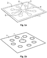
- Figure 1a illustrates a structure according to an embodiment.
- a structural layer 2 is formed in a sheet of substrate 1, due to the effect of which liquid can travel in the substrate sheet only along the liquid-flow channels 3 to the detection/reaction areas 4.
- a sample drop 5 is applied to the intersection 6 of the flow channels.
- the structural layer 2 extends through the entire depth of the substrate sheet in the thickness direction.
- Figure 1b shows the structure of a layer of the substrate 1.
- the substrate 1 has a hydrophobic area 19, a hydrophilic area 18 and a plurality of electrodes 17 being anodes and/or cathodes.
- the electrodes 17 are spaced such that when configured with other layers of substrate 1, electrodes 17 overlay or underlie electrodes 17 of the other layers of substrate 1.
- Figure 2 shows an example of liquid-flow guiding structural layers manufactured on paper (50 g/m2) made from Eucalyptus fibres. Due to the effect of the structural layers 16, the liquid can only progress along the liquid channels 7 - 11. Channel 7 is 4-mm wide and channel 11 is 0.25-mm wide. In the figure, drops of water 12, which have spread by capillary action in the channels, and coloured with foodstuffs colours are applied to the liquid channels.
- the structural layers 16 guiding the liquid flow are formed in the paper by flexo 15 printing three print layers of a 5 weight-% polystyrene-xylene solution on top of each other.
- An RK Flexiproof 100 unit was used as the printing device. The printing speed was 60 m/min. The printing cylinder pressure was optimized to achieve the best result. If a single unified printing-solution layer was printed on the rear side of the paper, a single patterned layer on the front side would be sufficient to create patterned liquid channels.
- Figure 3a shows schematically the structure according to an embodiment.
- a first hydrophobic print zone 42a and a second hydrophobic print zone 42b are printed on the substrate 40, between which remains an unprinted hydrophilic sample zone 44. Liquid brought to the sample zone 44 will remain in the zone in question, thanks to the print zones 42a, 42b.
- the width of a flow channel is typically 30 ⁇ m - 5 mm, particularly 0.25 mm - 4 mm.
- the polymer can be carried deeper into the substrate to reinforce the liquid-guiding effect of the print structures.
- a similar effect can also be achieved by increasing the pressure between the printing substrate and the printing cylinder.
- the polymer concentration, the printing pressure, and the number of printings are preferably selected in such a way that a structure zone extending to the full depth of the substrate is achieved.
- a unified or local barrier layer 46 can also be printed on the rear surface of the substrate, as shown in Figure 3b .
- This layer typically extends over the entire width of the sample zone 44 and prevents the liquid from coming through the substrate in its thickness direction.
- there is a depth-direction barrier layer 46 in the structure in addition to the print zones 42a and 42b acting as lateral barrier layers.
- the lateral liquid guiding effect improves and the need for print layers or pressure on the front surface of the substrate is reduced.
- the capillary volume decreases, the need for sample substantially decreases. The movement of foreign substances into the sample zone from the base of the substrate (e.g., a table top) is also effectively prevented.
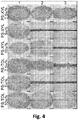
- Figure 4 shows the spreading of a sample solution in liquid channels made in different ways.
- PS-XYL polystyrene-xylene
- PS-TOL polystyrene-toluene
- Figure 5 shows the effect of the lateral width of the barrier zone on the capillary travel of a liquid.
- a 5-weight-% polystyrene-xylene solution was printed on chromatography paper as 100 - 800- ⁇ m rings (inner ring). Inside the ring, 5 ⁇ l of coloured deionized water was applied. It was observed that the lateral flow to the barrier zone was entirely prevented using a structural width of about 400 ⁇ m.
- aqueous liquid includes, but is not limited to, water, blood, urine, tears, sweat, plasma, saline and mucous.
- the device comprises a first layer of substrate material including at least one cathode and a second layer of substrate material attached on a surface of the first layer of substrate material and including at least one anode, which is aligned with the at least one cathode included in the first layer of substrate material.
- the structure is designed so that at least one hydrophilic separator area is formed between the at least one cathode and the at least one anode.
- the device also includes a third layer of substrate material positioned on the opposite face of the first layer of substrate material or the second layer of substrate material such that the third layer of substrate material forms a liquid flow guidance structure for guiding liquid to the at least one hydrophilic separator area.
- the opposite face refers to the face of a first layer or second layer that is oriented away from the second layer or first layer, respectively.
- the device also comprises at least one electrical conductor connected to at least one cathode or at least one anode. The device is adapted to produce voltage when the at least one hydrophilic separator area is contacted with an aqueous liquid.
- the liquid flow guidance structure is manufactured on a substrate sheet for example by flexo or gravure printing, using a printing solution, which changes the properties of the substrate sheet in such a way that the liquid flow is prevented in the area of the printed structural layers.
- a printing solution which changes the properties of the substrate sheet in such a way that the liquid flow is prevented in the area of the printed structural layers.
- Embodiments also provide the advantage that simple solutions, comprising a polymer and a solvent, or solutions substantially consisting of them, are considerably more economical than, for example, commercial photoresists, which are used in the methods according to the prior art.
- the penetration of the printing solution in the depth direction of the substrate sheet is regulated by adjusting the pressure between the printing cylinder and the substrate sheet, and viscosity of the printing solution.
- a suitable printing-cylinder pressure and making a printing solution with a suitable viscosity the solvent of which evaporates rapidly, the lateral spread of the printing solution is kept small and thus the edge areas of the structures guiding the liquid flow are made sharp.
- the properties of the printing solution can also be optimized by using a solvent with several different boiling points.
- the penetration of the printing solution into the substrate sheet can be boosted by printing several printing-solution layers on top of each other, or by applying more printing solution using, for example, screen printing.
- a printing-solution layer printed on the front side does not penetrate through the entire substrate, either a patterned or a unified printing-solution layer can be printed on the rear surface of the substrate.
- a structural layer guiding liquid flow is achieved.
- a unified printing-solution layer printed on the rear side has the advantage that it simultaneously acts as a protecting layer, which prevents the liquid from escaping through the under surface of the substrate.
- the substrate of the device may be selected from a diverse range of materials.
- the substrate is selected from the group of substrates consisting of textiles, such as, for example cotton, viscose and polyamide, non-woven materials such as, for example, knitted fabrics and netting fabrics, paper and paper board, and technical fabrics such as, for example GORE-TEX®.
- textiles such as, for example cotton, viscose and polyamide
- non-woven materials such as, for example, knitted fabrics and netting fabrics
- paper and paper board and technical fabrics
- GORE-TEX® e.g. GORE-TEX® is more breathable than nylon and thus the aqueous liquid closing the electrical circuit evaporates from the device more quickly, reducing the amount of time that the electrical circuit is closed and likewise the amount of time that voltage is produced.
- the first layer of substrate material, the second layer of substrate material and the third layer of substrate material are made of the same substrate material.
- the first layer of substrate material, the second layer of substrate material and the third layer of substrate material are different areas of a single substrate.
- the first layer, the second layer and the third layer of substrate material are a first area, second area and a third area on the substrate.
- the at least one electrical conductor is printed on a fourth area of the same single substrate.
- the first layer of substrate material further includes at least one anode in addition to the at least one cathode and the second layer of substrate material further includes at least one cathode in addition to the at least one anode.
- the device includes a hydrophilic separator area located between each anode-cathode or cathode-anode pair.
- the device contains at least one electrolyte within the at least one hydrophilic separator area.
- the device further comprises connectors for connection to a power source.
- the power source can for example be connected to the device with leads from the power source to electrodes of the device, i.e. at least one connection lead to an anode of the device and at least one connection lead to a cathode of the device.
- the device comprises a power source, wherein the power source is integrated in the substrate by printing, e.g. by inkjet printing or from the pen of a plotter. If inkjet printing is used, the printing is usually repeated a number of times, typically 10 to 30 times, such as 12 to 20 times.
- the power source can be printed on the substrate for example by flexo or gravure printing, or by screen printing.
- the source of energy is a renewable fuel.
- the source of energy comprises a fuel composition comprising at least one compound selected from the group consisting of monosaccharides, such as, for example, glucose, fructose, galactose and ribose, disaccharides such as, for example, lactose, sucrose, maltose, lactulose and cellobiose, alcohols such as, for example, ethanol, methanol, isopropyl alcohol, butanol, tertiary butanol, pentanol and hexanol, lactic acid, uric acid, ascorbic acid and urea.
- the source of energy is selected from the group consisting of biofuel cell and half enzymatic cell.
- the device comprises at least one cathode and at least one anode.
- the device comprises a plurality of anodes and a plurality of cathodes, one cathode and one anode forming a galvanic pair.
- the galvanic pairs are connected in series in one embodiment and in a further embodiment the galvanic pairs are connected in parallel. In a still further embodiment galvanic pairs are connected in a combination of both series and parallel.
- the cathode comprises an electrode material, such as an electrically conductive material.
- the electrode material is selected from the group of carbon, silver, gold, copper, aluminium, palladium, platinum, zinc and mixtures thereof.
- the anode comprises an electrode material, such as material selected from the group of carbon, silver, gold, copper, aluminium, palladium, platinum, zinc and mixtures thereof.
- the anode comprises a catalyst.
- the catalyst comprises at least one enzyme selected from the group consisting of glucose oxidase, lactate oxidase, urate oxidase and ascorbate oxidase.
- the cathode comprises a catalyst, such as at least one enzyme selected from the group consisting of glucose oxidase, monoamine oxidase, cytochrome P450 oxidase, NADPH oxidase, zanthine oxidase, L-gulonolactone, laccase, lysyl oxidase, cytochrome c oxidase, glutathione peroxidase, haloperoxidase, catalase, myeloperoxidase, thyroid peroxidase, vanadium bromoperoxidase and lactperoxidase.
- a method of producing a voltage in the device In order for the device to produce a voltage, the device is activated.
- a method of producing a voltage in a device of any of the above described embodiments comprises the step of contacting the substrate of the device with an aqueous liquid.
- the aqueous liquid may be selected from those liquids that may be considered to be biological fluids.
- the aqueous liquid is selected from the group consisting of water, urine, tears, saline, blood, plasma, pus, mucous, sweat and mixtures thereof.
- the device has a number of applications not only in cosmetics but also in healthcare and wellbeing.
- the device can be configured such that on folding the substrate, anodes and cathodes are positioned one underlying the other.
- a device is provided that may be attached by means of a pharmaceutically acceptable adhesive to an area of skin that is to be treated.
- One embodiment provides the device as described hereinbefore for use in the treatment of diseases.
- the device By activating the device with an aqueous liquid such as the sweat of the person to be treated an electrical voltage is produced and current flows to the skin. This current stimulates the skin enhancing e.g. blood flow.
- the device is provided for use in the treatment of diseases symptomized by poor blood circulation, such as, for example, preventing pain and diabetic ulcers, peripheral artery disease, alopecia and hair loss.
- the device is provided for use in the treatment of wounds, bruises and scars.
- the device is provided for use in the treatment of migraine.
- the device is provided for use in the treatment of hyperhidrosis.
- the device can also be used for the delivery of drugs by induction of a current over a treatment area.
- the device is provided for use in the treatment of pain, for example by transdermal drug delivery.
- the device is suitable as a tool in drug delivery, but it can also be used in cosmetics.
- the device is provided for enhancing delivery of cosmetic, well-being and personal care stimulant agents into skin.
- a method of producing a device for an electrochemical cell comprises the steps of printing at least one cathode on an at least one first area of a substrate, printing at least one anode on an at least one second area of the substrate, wherein the printings on the at least one first area and on the at least one second area are separated by an at least one third area of the substrate.
- the at least one third layer of substrate is provided with an at least one liquid flow guidance structure for guiding liquid.
- At least one electrical conductor is provided which is connected to the at least one cathode or the at least one anode, and the at least one anode is juxtaposed with the at least one cathode such that the device is adapted to produce voltage when it is contacted with an aqueous liquid.
- the juxtaposing of the at least one anode and the at least one cathode is carried out, for example, by folding the substrate so that the at least one anode and at least one cathode underlie and/or overlay an at least one anode and an at least one cathode.
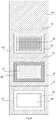
- Fig. 6A shows a first layer 61 of substrate material 65 and at least one cathode 66 included in the first layer 61.
- the at least one cathode 66 can be manufactured for example by printing as discussed earlier in this document.
- the first layer 61 includes also anodes 67.
- the first layer 61 also includes a separator layer 71 between the outer surface of the first layer 61 and the inner boundary of the cathode 66 or anode 67 inside the substrate material 65.
- the outer boundary of the cathode 66 or anode 67, i.e. the upper surface of the cathode 66 or anode 67 of the first layer 61 in the orientation of Fig. 6A can coincide the surface of the first layer 61 of substrate material 65 or can protrude outward from the surface of the first layer 61 of substrate material 65.
- Fig. 6A also shows a second layer 62 of substrate material 65 and at least one anode 67 included in the second layer 62.
- the at least one anode 67 can be manufactured for example by printing as discussed earlier in this document.
- the second layer 62 includes also cathodes 66.
- the second layer 62 comprises separator layers 71 between the outer surface of the first layer 61 and the inner boundaries of the cathodes 66 and anodes 67 inside the substrate material 65.
- Fig. 6A shows also a third layer 63 of substrate material 65 and at least one hydrophilic collection area 69 formed or left in the substrate material 65.
- the substrate material 65 is usually hydrophilic itself so that the hydrophilic collection areas 69 can be left untreated or can be provided with an at least one electrolyte in dry form.
- the at least one electrolyte can be provided in the separator layers 71 in the first layer 61 or the second layer 62 or in both the first layer 61 and the second layer 62.
- the substrate material 65 of the third layer 63 can be made hydrophobic using methods described above, for instance. Then, the hydrophobic areas form a liquid flow guidance structure, which guides the liquid flow by preventing the liquid from being absorbed into the areas the third layer 63 outside of the hydrophilic collection areas 69.
- the liquid flow guidance structure comprises liquid channels as described above.
- a hydrophobic pattern is made in the substrate material 65 of the third layer 63 outside of the hydrophilic collection areas 69 to form such liquid channels.
- the term collection area refers to the idea that sample fluid is transported by means of the liquid channels to the hydrophilic collection areas 69 from which the liquid is absorbed in between the electrodes 66 and 67 through one of the electrodes in order to activate the current production.
- Fig. 6A also shows a fourth layer 64 of substrate material 65 including electrical conductors 68 printed on its surface.
- At least one dry electrolyte material can be provided between the anodes 67 and cathodes 66 or in the vicinity of the anodes 67 and cathodes 66 such that electrolyte will be transported to the substrate area between the anodes 67 and cathodes 66 by means of liquid with which the device is contacted.
- the device can produce electricity efficiently also when the liquid is pure water as the electrolyte material provides the necessary ions.
- the electrolyte material can be, for example, a salt, such as ammonium chloride or zinc chloride or other suitable salt or a combination of salts.
- the device can also be designed to operate without electrolyte materials in the device itself but to be activated by the liquid with which the device is contacted, such as urine or sweat or other salty waters.
- a device for an electrochemical cell comprising:
- the first and second hydrophilic areas of the substrate coincide with the electrodes 66/67 and the separator layers 71, and the rest of the substrate material 65 acts as the hydrophobic area separating said hydrophilic areas.
- the device further comprises a third layer 63 of substrate material 65 comprising hydrophobic areas forming a liquid flow guidance structure (65/69 or liquid channels not shown in the figure) for guiding liquid to the at least one hydrophilic collector area 69 and therefrom to the separator layers 71, and the device is adapted to produce voltage when the separator layers 71 are contacted with an aqueous liquid.
- a liquid flow guidance structure 65/69 or liquid channels not shown in the figure
- Fig. 6c shows the positioning of the electrodes (66 and 67) within the substrate material 65 in more detail.
- the electrode is a cathode 66, but corresponding values and teachings apply also for anodes 67.
- Fig. 6c shows also the positioning of the separator layers 71.
- Fig. 6c shows also a thickness hs of the substrate material 65, a thickness hm of the electrode 66 and a thickness d of the the separator layer 71.
- the thickness d is measured between the inner boundary of electrode and the surface of the substrate material 65 to be placed facing the opposite electrode.
- the thickness hm is measured between the inner boundary of electrode and the outer surface of the electrode.
- t is 5-200 ⁇ m, such as 20-50 ⁇ m, wherein the outward protrusion of the electrode material facilitates the forming of electrical contact between the electrode 66, 67 and the conductor 68.
- d is 10-200 ⁇ m, such as 20-100 ⁇ m.
- the first electrodes 66/67 comprise a layer of electrode material at least partially absorbed within the first layer 61 of substrate material 65 through a first surface of the substrate material 65 (upper surface in Fig. 6a ), and the first layer 61 of substrate material 65 comprises a separator layer 71 between the layer of electrode material and a second surface of the substrate material 65 (lower surface in Fig. 6a ) opposite to the first surface of the substrate material 65.
- the electrode material that is for example printed on the substrate material 65 is at least partially absorbed in the substrate material 65 but not throughout the thickness of the first layer 61.
- the electrode material forms a layer acting as an electrode 66/67 on and/or inside the first layer 61, and the rest of the thickness of the first layer 61 acts as the separator layer 71.
- the second electrodes 67/66 comprise a layer of electrode material at least partially absorbed within the second layer 62 of substrate material 65 through a first surface of the substrate material 65 (lower surface in Fig. 6a ), and the second layer 62 of substrate material 65 comprises a separator layer 71 between the layer of electrode material and a second surface of the substrate material 65 (upper surface in Fig. 6a ) opposite to the first surface of the substrate material 65.
- the electrode material that is for example printed on the substrate material 65 is at least partially absorbed in the substrate material 65 but not throughout the thickness of the second layer 61. Instead, the electrode material forms a layer acting as an electrode 67/66 on and/or inside the second layer 62, and the rest of the thickness of the second layer 62 acts as the separator layer 71.
- the first layer 61 and the second layer 62 both comprise a separator layer 71 so that the distance between the electrodes 66 and 67 in an electrochemical cell is double the thickness of one separator layer 71.
- only one of the first layer 61 and the second layer 62 comprise a separator layer 71.
- an electrochemical cell can be manufactured without separate membranes or other elements acting as a separator element between the electrodes. Instead, the first layer 61 of substrate material 65 can be placed in direct contact with the second layer 62 of substrate material 65. This simplifies the structure and offers benefits in view of mass production of the electrochemical cells.
- the first layer 61 of substrate material 65 is in direct contact with the second layer 62 of substrate material 65 at least at the locations of the at least two first electrodes and the at least two second electrodes, a portion of the substrate material 65 separating the at least two first electrodes from the at least two second electrodes in the thickness direction of the substrate material 65.
- the substrate material 65 can be the same in each one of the layers 61, 62, 63 and 64.
- the structure can also be made by printing on a single layer of substrate material 65 and then cutting and juxtaposing the different layers or just folding the structure. The folding is especially practical in embodiments described in Figs 7 and 8 .
- the print patterns are designed so that the differently treated areas of the substrate material 65 are automatically aligned correctly with regard to each other when folded properly along a folding line 70.
- hydrophilic collector areas 69 By making an outward fold along line 70 between a first portion of substrate material 65 (lowest portion in Figs 7 and 8 ) comprising hydrophilic collector areas 69 and a second portion of substrate material 65 (lowest but one portion in Figs 7 and 8 ) comprising cathodes 66 and anodes 67, the hydrophilic collector areas 69 due to the nature of their positioning on the first portion of substrate material 65 become correctly aligned with regard to the cathodes 66 and anodes 67 of the second portion of substrate material.
- the fold provides a layered structure, said structure having a first layer 61 of substrate material 65 comprising cathodes 66 and anodes 67 and a third layer 63 of substrate material 65 comprising hydrophilic collector areas 69.
- the third layer 63 is made suitable for contacting a subject, e.g. suitable for contacting the skin, for instance.
- the cathodes 66 of the third portion of substrate material 65 become aligned with the anodes 67 of the second portion of substrate material 65.
- the anodes 67 of the third portion of substrate material 65 become aligned with the cathodes 66 of the second portion of substrate material 65.
- This fold provides a second layer 62 of substrate material 65 comprising cathodes 66 and anode 67 to the layered structure.
- the substrate material comprises also a fourth portion (top most portion in Figs 7 and 8 ).
- a fourth portion By making a further fold along a line 70 between the third portion of substrate material 65 comprising cathodes 66 and anodes 67 and a fourth portion of substrate material is provided according to an embodiment.
- the fourth portion can be used to create contacts between the galvanic pair, i.e. between cathodes 66 and anodes 67 depending on the type of connection (serial or parallel).
- the layer containing conductors can be easily configured such that the desired galvanic pairs are connected to each other.
- Products according to embodiments are suitable for use in the production of wearable flexible thin printed batteries.
Landscapes
- Engineering & Computer Science (AREA)
- Manufacturing & Machinery (AREA)
- Chemical & Material Sciences (AREA)
- Chemical Kinetics & Catalysis (AREA)
- Electrochemistry (AREA)
- General Chemical & Material Sciences (AREA)
- Health & Medical Sciences (AREA)
- Electrotherapy Devices (AREA)
- Biomedical Technology (AREA)
- Nuclear Medicine, Radiotherapy & Molecular Imaging (AREA)
- Radiology & Medical Imaging (AREA)
- Life Sciences & Earth Sciences (AREA)
- Animal Behavior & Ethology (AREA)
- General Health & Medical Sciences (AREA)
- Public Health (AREA)
- Veterinary Medicine (AREA)
- Secondary Cells (AREA)
- Medicinal Preparation (AREA)
- Battery Electrode And Active Subsutance (AREA)
Claims (15)
- Dispositif pour cellule électrochimique, comprenant :- une première couche (61) de matériau de substrat (65) ayant une pluralité de premières zones hydrophiles du substrat et au moins une zone hydrophobe séparant lesdites premières zones hydrophiles, la première couche de matériau de substrat comprenant au moins deux premières électrodes (66, 67) réalisées sur au moins deux premières zones hydrophiles ;- une deuxième couche (62) de matériau de substrat (65) ayant une pluralité de deuxièmes zones hydrophiles du substrat et au moins une zone hydrophobe séparant lesdites deuxièmes zones hydrophiles, la deuxième couche de matériau de substrat comprenant au moins deux secondes électrodes (67, 66) réalisées sur au moins deux deuxièmes zones hydrophiles ;- un ou plusieurs conducteurs électriques (68) connectés à au moins deux desdites premières électrodes ; et- dans lequel la première couche (61) de matériau de substrat (65) et la deuxième couche (62) de matériau de substrat (65) sont positionnées l'une sur l'autre de telle sorte que les au moins deux premières électrodes (66, 67) sont alignées avec les au moins deux secondes électrodes (67, 66) afin de former au moins deux cellules électrochimiques pour produire une tension lorsque les au moins deux zones hydrophiles sont mises en contact avec un liquide aqueux, dans lequel le dispositif passe d'un état inactif dans lequel le dispositif ne produit sensiblement aucune tension à un état actif dans lequel le dispositif produit une tension lorsqu'il est en contact avec le liquide aqueux.
- Dispositif selon la revendication 1, dans lequel la première couche de matériau de substrat et la deuxième couche de matériau de substrat sont constituées du même matériau de substrat, de préférence la première couche de matériau de substrat et la deuxième couche de matériau de substrat sont différentes zones d'un substrat unique.
- Dispositif selon l'une quelconque des revendications précédentes, dans lequel les zones hydrophiles de la première couche de matériau de substrat et de la deuxième couche de matériau de substrat se font face les unes les autres et les premières électrodes et les secondes électrodes sont alignées pour former des paires d'électrodes.
- Dispositif selon l'une quelconque des revendications précédentes, dans lequel les premières électrodes comprennent une couche de matériau d'électrode au moins partiellement absorbée à l'intérieur de la première couche de matériau de substrat à travers une première surface du matériau de substrat, et la première couche de matériau de substrat comprend une couche séparatrice entre la couche de matériau d'électrode et une seconde surface du matériau de substrat opposée à la première surface du matériau de substrat, et facultativement dans lequel les secondes électrodes comprennent une couche de matériau d'électrode au moins partiellement absorbée à l'intérieur de la deuxième couche de matériau de substrat à travers une première surface du matériau de substrat, et la première couche de matériau de substrat comprend une couche séparatrice entre la couche de matériau d'électrode et une seconde surface du matériau de substrat opposée à la première surface du matériau de substrat.
- Dispositif selon la revendication 4, dans lequel la couche séparatrice a une épaisseur d de 10 à 200 µm, telle que 20 à 100 µm.
- Dispositif selon l'une quelconque des revendications précédentes, comprenant en outre une troisième couche de matériau de substrat positionnée au-dessus des première ou deuxième couches de matériau de substrat, dans lequel la troisième couche de matériau de substrat est facultativement une troisième zone du même substrat unique, ladite troisième couche ayant au moins des troisièmes zones hydrophiles et au moins une troisième zone hydrophobe, de sorte qu'une ou plusieurs troisièmes zones hydrophiles sont alignées avec une ou plusieurs premières et deuxièmes zones hydrophiles, et facultativement la troisième couche de substrat forme une structure de guidage d'écoulement liquide composée de troisièmes zones hydrophiles et de troisièmes zones hydrophobes.
- Dispositif selon l'une quelconque des revendications précédentes, comprenant en outre une quatrième couche de matériau de substrat positionnée sous les première ou deuxième couches de matériau de substrat, dans lequel la quatrième couche de matériau de substrat est facultativement une quatrième zone du même substrat unique.
- Dispositif selon l'une quelconque des revendications précédentes, dans lequel les premières électrodes sont des anodes ou des cathodes et les secondes électrodes sont respectivement des cathodes ou des anodes, ou les premières électrodes comprennent à la fois des anodes et des cathodes et les secondes électrodes comprennent respectivement des cathodes et des anodes alignées pour former des paires de premières anodes d'électrode et de premières cathodes d'électrode ainsi que des paires de secondes anodes d'électrode et de secondes cathodes d'électrode.
- Dispositif selon l'une quelconque des revendications précédentes, dans lequel le substrat est choisi parmi le groupe de substrats poreux constitués de textiles, tels que, par exemple du coton, de la viscose et du polyamide, de matériaux non tissés tels que, par exemple, des tissus tricotés et tissus maillés, du papier et du carton et de tissus techniques tels que, par exemple Gore-Tex®.
- Dispositif selon l'une quelconque des revendications précédentes, dans lequel des cellules galvaniques sont formées entre une pluralité de premières électrodes et une pluralité de secondes électrodes lorsque le dispositif est mis en contact avec un liquide aqueux, et facultativement les cellules galvaniques sont connectées en série ou en en parallèle, de préférence au moins certaines des cellules galvaniques sont connectées en série et au moins certaines des cellules galvaniques sont connectées en parallèle.
- Dispositif selon l'une quelconque des revendications précédentes, dans lequel la première couche (61) de matériau de substrat (65) est en contact direct avec la deuxième couche (62) de matériau de substrat (65) au moins aux emplacements des au moins deux premières électrodes et des au moins deux secondes électrodes, une partie du matériau de substrat (65) séparant les au moins deux premières électrodes vis-à-vis des au moins deux secondes électrodes dans la direction d'épaisseur du matériau de substrat (65), et facultativement la première couche (61) de matériau de substrat (65) et la deuxième couche (62) de matériau de substrat (65) sont conçues pour être activées afin de fournir au moins deux cellules électrochimiques destinées à produire une tension lorsque les au moins deux zones hydrophiles sont en contact avec un liquide aqueux.
- Procédé de production d'une tension dans un dispositif selon l'une quelconque des revendications précédentes, comprenant l'étape de mise en contact du substrat du dispositif avec un liquide aqueux, de préférence dans lequel le liquide aqueux est choisi parmi le groupe constitué d'eau, urine, larmes, solution saline, sang, plasma, pus, mucus, sueur et de mélanges de ceux-ci.
- Dispositif selon l'une quelconque des revendications 1 à 11 pour une utilisation dans le traitement d'une maladie, de préférence pour une utilisation dans le traitement de maladies ayant pour symptôme une mauvaise circulation sanguine, telles que, par exemple, pour prévenir une douleur et des ulcères diabétiques, une maladie artérielle périphérique, une alopécie et une chute des cheveux, en particulier pour une utilisation dans le traitement d'une affection choisie parmi le groupe constitué de plaies, d'ecchymoses, de cicatrices, d'hyperhidrose et de migraine.
- Dispositif selon l'une quelconque des revendications 1 à 11, destiné à être utilisé pour améliorer une administration d'un produit cosmétique, d'un produit de bien-être, de médicaments stimulants, par exemple de la nicotine, et d'agents stimulants de soins personnels dans la peau.
- Procédé de production d'un dispositif pour cellule électrochimique, comprenant les étapes consistant à :- fournir un matériau de substrat (65) ayant une pluralité de zones hydrophiles du substrat et au moins une zone hydrophobe séparant lesdites zones hydrophiles ;- imprimer des électrodes (66, 67) sur des zones hydrophiles de la première couche de matériau de substrat ;- plier le matériau de substrat (65) pour formerune première couche (61) de matériau de substrat (65) ayant une pluralité de premières zones hydrophiles du substrat et au moins une zone hydrophobe séparant lesdites premières zones hydrophiles, la première couche de matériau de substrat comprenant au moins deux premières électrodes (66, 67) réalisées sur au moins deux premières zones hydrophiles ; etune deuxième couche (62) de matériau de substrat (65) ayant une pluralité de deuxièmes zones hydrophiles du substrat et au moins une zone hydrophobe séparant lesdites deuxièmes zones hydrophiles, la deuxième couche de matériau de substrat comprenant au moins deux secondes électrodes (67, 66) réalisées sur au moins deux deuxièmes zones hydrophiles ;dans lequel la première couche (61) de matériau de substrat (65) et la deuxième couche (62) de matériau de substrat (65) sont positionnées l'une sur l'autre de telle sorte que les au moins deux premières électrodes (66, 67) sont alignées avec les au moins deux secondes électrodes (67, 66) afin de former au moins deux cellules électrochimiques pour produire une tension lorsque les au moins deux zones hydrophiles sont mises en contact avec un liquide aqueux ;- réaliser un ou plusieurs conducteurs électriques (68) connectés à au moins deux desdites premières électrodes.
Applications Claiming Priority (2)
| Application Number | Priority Date | Filing Date | Title |
|---|---|---|---|
| FI20155619 | 2015-08-28 | ||
| PCT/FI2016/050589 WO2017037336A1 (fr) | 2015-08-28 | 2016-08-26 | Dispositif pour cellule électrochimique |
Publications (3)
| Publication Number | Publication Date |
|---|---|
| EP3341992A1 EP3341992A1 (fr) | 2018-07-04 |
| EP3341992A4 EP3341992A4 (fr) | 2019-03-13 |
| EP3341992B1 true EP3341992B1 (fr) | 2020-03-11 |
Family
ID=58188509
Family Applications (1)
| Application Number | Title | Priority Date | Filing Date |
|---|---|---|---|
| EP16840880.5A Active EP3341992B1 (fr) | 2015-08-28 | 2016-08-26 | Dispositif pour cellule électrochimique |
Country Status (4)
| Country | Link |
|---|---|
| US (1) | US10700363B2 (fr) |
| EP (1) | EP3341992B1 (fr) |
| CN (1) | CN107925094B (fr) |
| WO (1) | WO2017037336A1 (fr) |
Families Citing this family (11)
| Publication number | Priority date | Publication date | Assignee | Title |
|---|---|---|---|---|
| DE102018215942A1 (de) * | 2018-09-19 | 2020-03-19 | Robert Bosch Gmbh | Galvanische Zelle zum Bereitstellen einer Gleichspannung für eine am Körper tragbare Vorrichtung, sowie am Körper tragbare Vorrichtung |
| CN110772378A (zh) * | 2019-10-31 | 2020-02-11 | 京东方科技集团股份有限公司 | 敷料 |
| CN113036164B (zh) * | 2019-12-24 | 2022-05-27 | 大连大学 | 一种基于介孔泡沫碳的复合电极制备方法及应用 |
| CN112774024B (zh) * | 2020-12-29 | 2025-08-05 | 江苏海莱新创医疗科技有限公司 | 一种应用于人体皮肤有吸湿结构的电极垫 |
| CN113422083A (zh) * | 2021-06-03 | 2021-09-21 | 西南大学 | 汗液激发的分段式电池、制备方法及用途 |
| FR3138989A1 (fr) * | 2022-08-26 | 2024-03-01 | Feeligreen | Dispositif de traitement de la peau |
| FR3138988A1 (fr) * | 2022-08-26 | 2024-03-01 | Feeligreen | Dispositif de traitement de la peau |
| FR3149795A1 (fr) * | 2023-06-16 | 2024-12-20 | Feeligreen | Dispositif de traitement de la peau |
| FR3149787A1 (fr) * | 2023-06-16 | 2024-12-20 | Feeligreen | Dispositif de traitement de la peau |
| FR3149789A1 (fr) * | 2023-06-16 | 2024-12-20 | Feeligreen | Dispositif de traitement de la peau |
| FR3152229A1 (fr) * | 2023-08-25 | 2025-02-28 | Feeligreen | Dispositif de traitement de la peau |
Family Cites Families (23)
| Publication number | Priority date | Publication date | Assignee | Title |
|---|---|---|---|---|
| JPH0554895A (ja) | 1991-08-24 | 1993-03-05 | Sony Chem Corp | 薄型電池およびその製造方法 |
| US6379835B1 (en) | 1999-01-12 | 2002-04-30 | Morgan Adhesives Company | Method of making a thin film battery |
| US6745071B1 (en) * | 2003-02-21 | 2004-06-01 | Birch Point Medical, Inc. | Iontophoretic drug delivery system |
| KR100590376B1 (ko) | 2003-03-20 | 2006-06-19 | 마쯔시다덴기산교 가부시키가이샤 | 집합전지 |
| DE602004017720D1 (de) * | 2003-06-02 | 2008-12-24 | Power Paper Ltd | Bausatz, vorrichtung und verfahren zur gesteuerten abgabe eines oxidationsmittels in die haut |
| US7457667B2 (en) | 2004-02-19 | 2008-11-25 | Silverleaf Medical Products, Inc. | Current producing surface for a wound dressing |
| GB0506598D0 (en) | 2005-03-31 | 2005-05-04 | Inverness Medical Switzerland | Analysis device |
| FI20061064A0 (fi) | 2006-06-19 | 2006-12-01 | Valtion Teknillinen | Uudet ohutkalvorakenteet |
| FI20060602A0 (fi) | 2006-06-19 | 2006-06-19 | Valtion Teknillinen | Uudet ohutkalvorakenteet |
| US8150525B2 (en) | 2008-08-27 | 2012-04-03 | Johnson & Johnson Consumer Companies, Inc. | Treatment of hyperhydrosis |
| FR2941332B1 (fr) * | 2009-01-20 | 2011-04-01 | Commissariat Energie Atomique | Pile electrochimique integree dans un vetement utilisant un fluide physiologique comme electrolyte |
| US8744567B2 (en) | 2009-11-13 | 2014-06-03 | Johnson & Johnson Consumer Companies, Inc. | Galvanic skin treatment device |
| FI20096334A0 (fi) | 2009-12-15 | 2009-12-15 | Valtion Teknillinen | Menetelmä nestevirtausta ohjaavien rakennekerrosten valmistamiseksi huokoisille substraattikalvoille |
| WO2012138354A1 (fr) * | 2011-04-08 | 2012-10-11 | Empire Technology Development Llc | Batterie activée par l'humidité |
| FI123323B (fi) | 2011-06-14 | 2013-02-28 | Teknologian Tutkimuskeskus Vtt | Piilokuvioiden muodostaminen huokoisille substraateille |
| WO2013130145A2 (fr) | 2011-11-30 | 2013-09-06 | The Regents Of The University Of California | Piles à biocombustible imprimées |
| CN102593494A (zh) | 2012-02-27 | 2012-07-18 | 中国科学院长春应用化学研究所 | 一种酶生物燃料电池及其制备方法 |
| WO2014071572A1 (fr) | 2012-11-07 | 2014-05-15 | Empire Technology Development Llc | Dispositifs activés par du liquide alimentés par des batteries à hydrogel et procédés associés |
| US20140295244A1 (en) * | 2013-03-29 | 2014-10-02 | Research Foundation Of The City University Of New York | Printed flexible battery |
| JP6092469B2 (ja) | 2013-05-02 | 2017-03-08 | ボマリス イノベーションズ インコーポレイテッド | 拡張可能な創傷被覆材 |
| WO2015160944A1 (fr) * | 2014-04-15 | 2015-10-22 | North Carolina Agricultural And Technical State University | Pile au magnésium à base de papier et son utilisation |
| CN104225787B (zh) * | 2014-08-26 | 2016-12-07 | 中国人民解放军军事医学科学院放射与辐射医学研究所 | 伤口敷料 |
| CN104280444B (zh) * | 2014-10-15 | 2019-12-17 | 南京皓运投资管理有限公司 | 汗液收集及分析系统及其制作方法 |
-
2016
- 2016-08-26 EP EP16840880.5A patent/EP3341992B1/fr active Active
- 2016-08-26 CN CN201680050215.1A patent/CN107925094B/zh not_active Expired - Fee Related
- 2016-08-26 US US15/756,074 patent/US10700363B2/en not_active Expired - Fee Related
- 2016-08-26 WO PCT/FI2016/050589 patent/WO2017037336A1/fr not_active Ceased
Non-Patent Citations (1)
| Title |
|---|
| None * |
Also Published As
| Publication number | Publication date |
|---|---|
| US20180241048A1 (en) | 2018-08-23 |
| EP3341992A1 (fr) | 2018-07-04 |
| CN107925094B (zh) | 2021-03-05 |
| CN107925094A (zh) | 2018-04-17 |
| EP3341992A4 (fr) | 2019-03-13 |
| WO2017037336A1 (fr) | 2017-03-09 |
| US10700363B2 (en) | 2020-06-30 |
Similar Documents
| Publication | Publication Date | Title |
|---|---|---|
| EP3341992B1 (fr) | Dispositif pour cellule électrochimique | |
| US8343147B2 (en) | Electrolytic tissue treatment | |
| CN102711905B (zh) | 流电皮肤治疗装置 | |
| US20070060862A1 (en) | Method for administering electricity with particlulates | |
| US20060105420A1 (en) | Compositions and methods for enhancement of transdermal analyte flux | |
| US20100228180A1 (en) | Power Source Electrode Treatment Device | |
| WO2007071562A1 (fr) | Capteur en sandwich destine a determiner une concentration d'analyte | |
| CA2155107C (fr) | Dispositif d'administration de medicament actif et methode de preparation | |
| EP3801739B1 (fr) | Appareil d'augmentation de l'absorption de médicaments et de cosméceutiques à travers la peau de l'utilisateur | |
| WO2008157485A1 (fr) | Système de concentration de courant et procédé pour l'administration électrocinétique de médicaments | |
| EP1457233A1 (fr) | Système d'administration de médicaments transdermique avec electrode à mailles | |
| CN115738062A (zh) | 微电流微针阵列 | |
| WO1999052590A1 (fr) | Systeme d'application transdermal (tds) dote d'un reseau d'electrodes | |
| KR102816767B1 (ko) | 생체분해성 금속을 포함하는 자가 전류 발생 피부 적용 패치 | |
| FI127226B (en) | PROCEDURE AND DEVICE FOR SKIN TREATMENT | |
| JP7842503B2 (ja) | 生体内分解性金属を含む自己電流発生皮膚適用パッチ | |
| KR20220144587A (ko) | 입자 형태의 양극 및 패턴 형성된 음극을 포함하는 마스크 팩 | |
| CN117258126A (zh) | 复合面膜 | |
| KR102288681B1 (ko) | 전위차 소재를 이용하여 전류의 방향성을 가지도록 패턴된 전도성 분리형 마스크팩 시트 및 제조방법 | |
| KR20220144585A (ko) | 양극 및 음극이 패턴 형성된 마스크 팩 | |
| CN117136087A (zh) | 经皮二氢递送装置 | |
| JP2007244700A (ja) | イオントフォレーシス装置 | |
| JP2008000543A (ja) | イオントフォレーシス装置 | |
| JP2007244491A (ja) | イオントフォレーシス装置 | |
| HK1174867A (en) | Galvanic skin treatment device |
Legal Events
| Date | Code | Title | Description |
|---|---|---|---|
| STAA | Information on the status of an ep patent application or granted ep patent |
Free format text: STATUS: THE INTERNATIONAL PUBLICATION HAS BEEN MADE |
|
| PUAI | Public reference made under article 153(3) epc to a published international application that has entered the european phase |
Free format text: ORIGINAL CODE: 0009012 |
|
| STAA | Information on the status of an ep patent application or granted ep patent |
Free format text: STATUS: REQUEST FOR EXAMINATION WAS MADE |
|
| 17P | Request for examination filed |
Effective date: 20180209 |
|
| AK | Designated contracting states |
Kind code of ref document: A1 Designated state(s): AL AT BE BG CH CY CZ DE DK EE ES FI FR GB GR HR HU IE IS IT LI LT LU LV MC MK MT NL NO PL PT RO RS SE SI SK SM TR |
|
| AX | Request for extension of the european patent |
Extension state: BA ME |
|
| DAV | Request for validation of the european patent (deleted) | ||
| DAX | Request for extension of the european patent (deleted) | ||
| A4 | Supplementary search report drawn up and despatched |
Effective date: 20190211 |
|
| RIC1 | Information provided on ipc code assigned before grant |
Ipc: H01M 6/32 20060101AFI20190205BHEP Ipc: H01M 4/04 20060101ALI20190205BHEP Ipc: H01M 6/40 20060101ALI20190205BHEP Ipc: A61N 1/04 20060101ALI20190205BHEP Ipc: H01M 4/86 20060101ALI20190205BHEP Ipc: A61N 1/30 20060101ALI20190205BHEP Ipc: B41M 3/00 20060101ALI20190205BHEP Ipc: H01M 4/08 20060101ALI20190205BHEP Ipc: H01M 2/16 20060101ALI20190205BHEP Ipc: H01M 6/12 20060101ALI20190205BHEP Ipc: H01M 2/14 20060101ALI20190205BHEP Ipc: H01M 8/00 20160101ALI20190205BHEP |
|
| REG | Reference to a national code |
Ref country code: DE Ref legal event code: R079 Ref document number: 602016031757 Country of ref document: DE Free format text: PREVIOUS MAIN CLASS: H01M0006320000 Ipc: H01M0006040000 |
|
| RIC1 | Information provided on ipc code assigned before grant |
Ipc: H01M 6/32 20060101ALI20190920BHEP Ipc: H01M 6/46 20060101ALI20190920BHEP Ipc: A61N 1/30 20060101ALI20190920BHEP Ipc: A61N 1/20 20060101ALI20190920BHEP Ipc: H01M 6/04 20060101AFI20190920BHEP Ipc: A61N 1/04 20060101ALI20190920BHEP Ipc: H01M 6/40 20060101ALI20190920BHEP |
|
| GRAP | Despatch of communication of intention to grant a patent |
Free format text: ORIGINAL CODE: EPIDOSNIGR1 |
|
| STAA | Information on the status of an ep patent application or granted ep patent |
Free format text: STATUS: GRANT OF PATENT IS INTENDED |
|
| INTG | Intention to grant announced |
Effective date: 20191121 |
|
| GRAS | Grant fee paid |
Free format text: ORIGINAL CODE: EPIDOSNIGR3 |
|
| GRAA | (expected) grant |
Free format text: ORIGINAL CODE: 0009210 |
|
| STAA | Information on the status of an ep patent application or granted ep patent |
Free format text: STATUS: THE PATENT HAS BEEN GRANTED |
|
| AK | Designated contracting states |
Kind code of ref document: B1 Designated state(s): AL AT BE BG CH CY CZ DE DK EE ES FI FR GB GR HR HU IE IS IT LI LT LU LV MC MK MT NL NO PL PT RO RS SE SI SK SM TR |
|
| REG | Reference to a national code |
Ref country code: GB Ref legal event code: FG4D |
|
| REG | Reference to a national code |
Ref country code: CH Ref legal event code: EP |
|
| REG | Reference to a national code |
Ref country code: AT Ref legal event code: REF Ref document number: 1244299 Country of ref document: AT Kind code of ref document: T Effective date: 20200315 |
|
| REG | Reference to a national code |
Ref country code: IE Ref legal event code: FG4D |
|
| REG | Reference to a national code |
Ref country code: DE Ref legal event code: R096 Ref document number: 602016031757 Country of ref document: DE |
|
| PG25 | Lapsed in a contracting state [announced via postgrant information from national office to epo] |
Ref country code: RS Free format text: LAPSE BECAUSE OF FAILURE TO SUBMIT A TRANSLATION OF THE DESCRIPTION OR TO PAY THE FEE WITHIN THE PRESCRIBED TIME-LIMIT Effective date: 20200311 Ref country code: NO Free format text: LAPSE BECAUSE OF FAILURE TO SUBMIT A TRANSLATION OF THE DESCRIPTION OR TO PAY THE FEE WITHIN THE PRESCRIBED TIME-LIMIT Effective date: 20200611 Ref country code: FI Free format text: LAPSE BECAUSE OF FAILURE TO SUBMIT A TRANSLATION OF THE DESCRIPTION OR TO PAY THE FEE WITHIN THE PRESCRIBED TIME-LIMIT Effective date: 20200311 |
|
| REG | Reference to a national code |
Ref country code: NL Ref legal event code: MP Effective date: 20200311 |
|
| PG25 | Lapsed in a contracting state [announced via postgrant information from national office to epo] |
Ref country code: HR Free format text: LAPSE BECAUSE OF FAILURE TO SUBMIT A TRANSLATION OF THE DESCRIPTION OR TO PAY THE FEE WITHIN THE PRESCRIBED TIME-LIMIT Effective date: 20200311 Ref country code: LV Free format text: LAPSE BECAUSE OF FAILURE TO SUBMIT A TRANSLATION OF THE DESCRIPTION OR TO PAY THE FEE WITHIN THE PRESCRIBED TIME-LIMIT Effective date: 20200311 Ref country code: SE Free format text: LAPSE BECAUSE OF FAILURE TO SUBMIT A TRANSLATION OF THE DESCRIPTION OR TO PAY THE FEE WITHIN THE PRESCRIBED TIME-LIMIT Effective date: 20200311 Ref country code: GR Free format text: LAPSE BECAUSE OF FAILURE TO SUBMIT A TRANSLATION OF THE DESCRIPTION OR TO PAY THE FEE WITHIN THE PRESCRIBED TIME-LIMIT Effective date: 20200612 Ref country code: BG Free format text: LAPSE BECAUSE OF FAILURE TO SUBMIT A TRANSLATION OF THE DESCRIPTION OR TO PAY THE FEE WITHIN THE PRESCRIBED TIME-LIMIT Effective date: 20200611 |
|
| REG | Reference to a national code |
Ref country code: LT Ref legal event code: MG4D |
|
| PG25 | Lapsed in a contracting state [announced via postgrant information from national office to epo] |
Ref country code: NL Free format text: LAPSE BECAUSE OF FAILURE TO SUBMIT A TRANSLATION OF THE DESCRIPTION OR TO PAY THE FEE WITHIN THE PRESCRIBED TIME-LIMIT Effective date: 20200311 |
|
| PG25 | Lapsed in a contracting state [announced via postgrant information from national office to epo] |
Ref country code: SM Free format text: LAPSE BECAUSE OF FAILURE TO SUBMIT A TRANSLATION OF THE DESCRIPTION OR TO PAY THE FEE WITHIN THE PRESCRIBED TIME-LIMIT Effective date: 20200311 Ref country code: EE Free format text: LAPSE BECAUSE OF FAILURE TO SUBMIT A TRANSLATION OF THE DESCRIPTION OR TO PAY THE FEE WITHIN THE PRESCRIBED TIME-LIMIT Effective date: 20200311 Ref country code: LT Free format text: LAPSE BECAUSE OF FAILURE TO SUBMIT A TRANSLATION OF THE DESCRIPTION OR TO PAY THE FEE WITHIN THE PRESCRIBED TIME-LIMIT Effective date: 20200311 Ref country code: CZ Free format text: LAPSE BECAUSE OF FAILURE TO SUBMIT A TRANSLATION OF THE DESCRIPTION OR TO PAY THE FEE WITHIN THE PRESCRIBED TIME-LIMIT Effective date: 20200311 Ref country code: RO Free format text: LAPSE BECAUSE OF FAILURE TO SUBMIT A TRANSLATION OF THE DESCRIPTION OR TO PAY THE FEE WITHIN THE PRESCRIBED TIME-LIMIT Effective date: 20200311 Ref country code: PT Free format text: LAPSE BECAUSE OF FAILURE TO SUBMIT A TRANSLATION OF THE DESCRIPTION OR TO PAY THE FEE WITHIN THE PRESCRIBED TIME-LIMIT Effective date: 20200805 Ref country code: SK Free format text: LAPSE BECAUSE OF FAILURE TO SUBMIT A TRANSLATION OF THE DESCRIPTION OR TO PAY THE FEE WITHIN THE PRESCRIBED TIME-LIMIT Effective date: 20200311 Ref country code: IS Free format text: LAPSE BECAUSE OF FAILURE TO SUBMIT A TRANSLATION OF THE DESCRIPTION OR TO PAY THE FEE WITHIN THE PRESCRIBED TIME-LIMIT Effective date: 20200711 |
|
| REG | Reference to a national code |
Ref country code: AT Ref legal event code: MK05 Ref document number: 1244299 Country of ref document: AT Kind code of ref document: T Effective date: 20200311 |
|
| REG | Reference to a national code |
Ref country code: DE Ref legal event code: R097 Ref document number: 602016031757 Country of ref document: DE |
|
| PLBE | No opposition filed within time limit |
Free format text: ORIGINAL CODE: 0009261 |
|
| STAA | Information on the status of an ep patent application or granted ep patent |
Free format text: STATUS: NO OPPOSITION FILED WITHIN TIME LIMIT |
|
| PG25 | Lapsed in a contracting state [announced via postgrant information from national office to epo] |
Ref country code: DK Free format text: LAPSE BECAUSE OF FAILURE TO SUBMIT A TRANSLATION OF THE DESCRIPTION OR TO PAY THE FEE WITHIN THE PRESCRIBED TIME-LIMIT Effective date: 20200311 Ref country code: AT Free format text: LAPSE BECAUSE OF FAILURE TO SUBMIT A TRANSLATION OF THE DESCRIPTION OR TO PAY THE FEE WITHIN THE PRESCRIBED TIME-LIMIT Effective date: 20200311 Ref country code: ES Free format text: LAPSE BECAUSE OF FAILURE TO SUBMIT A TRANSLATION OF THE DESCRIPTION OR TO PAY THE FEE WITHIN THE PRESCRIBED TIME-LIMIT Effective date: 20200311 Ref country code: IT Free format text: LAPSE BECAUSE OF FAILURE TO SUBMIT A TRANSLATION OF THE DESCRIPTION OR TO PAY THE FEE WITHIN THE PRESCRIBED TIME-LIMIT Effective date: 20200311 |
|
| 26N | No opposition filed |
Effective date: 20201214 |
|
| PG25 | Lapsed in a contracting state [announced via postgrant information from national office to epo] |
Ref country code: PL Free format text: LAPSE BECAUSE OF FAILURE TO SUBMIT A TRANSLATION OF THE DESCRIPTION OR TO PAY THE FEE WITHIN THE PRESCRIBED TIME-LIMIT Effective date: 20200311 Ref country code: SI Free format text: LAPSE BECAUSE OF FAILURE TO SUBMIT A TRANSLATION OF THE DESCRIPTION OR TO PAY THE FEE WITHIN THE PRESCRIBED TIME-LIMIT Effective date: 20200311 |
|
| PG25 | Lapsed in a contracting state [announced via postgrant information from national office to epo] |
Ref country code: MC Free format text: LAPSE BECAUSE OF FAILURE TO SUBMIT A TRANSLATION OF THE DESCRIPTION OR TO PAY THE FEE WITHIN THE PRESCRIBED TIME-LIMIT Effective date: 20200311 |
|
| PG25 | Lapsed in a contracting state [announced via postgrant information from national office to epo] |
Ref country code: LU Free format text: LAPSE BECAUSE OF NON-PAYMENT OF DUE FEES Effective date: 20200826 |
|
| REG | Reference to a national code |
Ref country code: BE Ref legal event code: MM Effective date: 20200831 |
|
| PG25 | Lapsed in a contracting state [announced via postgrant information from national office to epo] |
Ref country code: IE Free format text: LAPSE BECAUSE OF NON-PAYMENT OF DUE FEES Effective date: 20200826 Ref country code: BE Free format text: LAPSE BECAUSE OF NON-PAYMENT OF DUE FEES Effective date: 20200831 |
|
| PGFP | Annual fee paid to national office [announced via postgrant information from national office to epo] |
Ref country code: FR Payment date: 20210819 Year of fee payment: 6 |
|
| PGFP | Annual fee paid to national office [announced via postgrant information from national office to epo] |
Ref country code: CH Payment date: 20210819 Year of fee payment: 6 Ref country code: GB Payment date: 20210824 Year of fee payment: 6 Ref country code: DE Payment date: 20210819 Year of fee payment: 6 |
|
| PG25 | Lapsed in a contracting state [announced via postgrant information from national office to epo] |
Ref country code: TR Free format text: LAPSE BECAUSE OF FAILURE TO SUBMIT A TRANSLATION OF THE DESCRIPTION OR TO PAY THE FEE WITHIN THE PRESCRIBED TIME-LIMIT Effective date: 20200311 Ref country code: MT Free format text: LAPSE BECAUSE OF FAILURE TO SUBMIT A TRANSLATION OF THE DESCRIPTION OR TO PAY THE FEE WITHIN THE PRESCRIBED TIME-LIMIT Effective date: 20200311 Ref country code: CY Free format text: LAPSE BECAUSE OF FAILURE TO SUBMIT A TRANSLATION OF THE DESCRIPTION OR TO PAY THE FEE WITHIN THE PRESCRIBED TIME-LIMIT Effective date: 20200311 |
|
| PG25 | Lapsed in a contracting state [announced via postgrant information from national office to epo] |
Ref country code: MK Free format text: LAPSE BECAUSE OF FAILURE TO SUBMIT A TRANSLATION OF THE DESCRIPTION OR TO PAY THE FEE WITHIN THE PRESCRIBED TIME-LIMIT Effective date: 20200311 Ref country code: AL Free format text: LAPSE BECAUSE OF FAILURE TO SUBMIT A TRANSLATION OF THE DESCRIPTION OR TO PAY THE FEE WITHIN THE PRESCRIBED TIME-LIMIT Effective date: 20200311 |
|
| REG | Reference to a national code |
Ref country code: DE Ref legal event code: R119 Ref document number: 602016031757 Country of ref document: DE |
|
| REG | Reference to a national code |
Ref country code: CH Ref legal event code: PL |
|
| GBPC | Gb: european patent ceased through non-payment of renewal fee |
Effective date: 20220826 |
|
| PG25 | Lapsed in a contracting state [announced via postgrant information from national office to epo] |
Ref country code: LI Free format text: LAPSE BECAUSE OF NON-PAYMENT OF DUE FEES Effective date: 20220831 Ref country code: CH Free format text: LAPSE BECAUSE OF NON-PAYMENT OF DUE FEES Effective date: 20220831 |
|
| PG25 | Lapsed in a contracting state [announced via postgrant information from national office to epo] |
Ref country code: FR Free format text: LAPSE BECAUSE OF NON-PAYMENT OF DUE FEES Effective date: 20220831 Ref country code: DE Free format text: LAPSE BECAUSE OF NON-PAYMENT OF DUE FEES Effective date: 20230301 |
|
| PG25 | Lapsed in a contracting state [announced via postgrant information from national office to epo] |
Ref country code: GB Free format text: LAPSE BECAUSE OF NON-PAYMENT OF DUE FEES Effective date: 20220826 |