EP3342302A1 - Partie semelle - Google Patents
Partie semelle Download PDFInfo
- Publication number
- EP3342302A1 EP3342302A1 EP17200771.8A EP17200771A EP3342302A1 EP 3342302 A1 EP3342302 A1 EP 3342302A1 EP 17200771 A EP17200771 A EP 17200771A EP 3342302 A1 EP3342302 A1 EP 3342302A1
- Authority
- EP
- European Patent Office
- Prior art keywords
- sole
- heel
- stiffening element
- sole portion
- longitudinal direction
- Prior art date
- Legal status (The legal status is an assumption and is not a legal conclusion. Google has not performed a legal analysis and makes no representation as to the accuracy of the status listed.)
- Withdrawn
Links
Images


Classifications
-
- A—HUMAN NECESSITIES
- A43—FOOTWEAR
- A43B—CHARACTERISTIC FEATURES OF FOOTWEAR; PARTS OF FOOTWEAR
- A43B21/00—Heels; Top-pieces or top-lifts
- A43B21/36—Heels; Top-pieces or top-lifts characterised by their attachment; Securing devices for the attaching means
- A43B21/39—Heels; Top-pieces or top-lifts characterised by their attachment; Securing devices for the attaching means by rib groove
- A43B21/40—Heels; Top-pieces or top-lifts characterised by their attachment; Securing devices for the attaching means by rib groove by dovetail
-
- A—HUMAN NECESSITIES
- A43—FOOTWEAR
- A43B—CHARACTERISTIC FEATURES OF FOOTWEAR; PARTS OF FOOTWEAR
- A43B13/00—Soles; Sole-and-heel integral units
- A43B13/14—Soles; Sole-and-heel integral units characterised by the constructive form
- A43B13/18—Resilient soles
- A43B13/181—Resiliency achieved by the structure of the sole
- A43B13/183—Leaf springs
-
- A—HUMAN NECESSITIES
- A43—FOOTWEAR
- A43B—CHARACTERISTIC FEATURES OF FOOTWEAR; PARTS OF FOOTWEAR
- A43B21/00—Heels; Top-pieces or top-lifts
- A43B21/36—Heels; Top-pieces or top-lifts characterised by their attachment; Securing devices for the attaching means
-
- A—HUMAN NECESSITIES
- A43—FOOTWEAR
- A43B—CHARACTERISTIC FEATURES OF FOOTWEAR; PARTS OF FOOTWEAR
- A43B21/00—Heels; Top-pieces or top-lifts
- A43B21/36—Heels; Top-pieces or top-lifts characterised by their attachment; Securing devices for the attaching means
- A43B21/37—Heels; Top-pieces or top-lifts characterised by their attachment; Securing devices for the attaching means by hook-shaped or bent attaching means
-
- A—HUMAN NECESSITIES
- A43—FOOTWEAR
- A43B—CHARACTERISTIC FEATURES OF FOOTWEAR; PARTS OF FOOTWEAR
- A43B21/00—Heels; Top-pieces or top-lifts
- A43B21/36—Heels; Top-pieces or top-lifts characterised by their attachment; Securing devices for the attaching means
- A43B21/39—Heels; Top-pieces or top-lifts characterised by their attachment; Securing devices for the attaching means by rib groove
-
- A—HUMAN NECESSITIES
- A43—FOOTWEAR
- A43B—CHARACTERISTIC FEATURES OF FOOTWEAR; PARTS OF FOOTWEAR
- A43B21/00—Heels; Top-pieces or top-lifts
- A43B21/36—Heels; Top-pieces or top-lifts characterised by their attachment; Securing devices for the attaching means
- A43B21/42—Heels with replaceable or adjustable parts, e.g. top lift
-
- A—HUMAN NECESSITIES
- A43—FOOTWEAR
- A43B—CHARACTERISTIC FEATURES OF FOOTWEAR; PARTS OF FOOTWEAR
- A43B21/00—Heels; Top-pieces or top-lifts
- A43B21/36—Heels; Top-pieces or top-lifts characterised by their attachment; Securing devices for the attaching means
- A43B21/47—Heels; Top-pieces or top-lifts characterised by their attachment; Securing devices for the attaching means by resilient means
-
- A—HUMAN NECESSITIES
- A43—FOOTWEAR
- A43B—CHARACTERISTIC FEATURES OF FOOTWEAR; PARTS OF FOOTWEAR
- A43B3/00—Footwear characterised by the shape or the use
- A43B3/24—Collapsible or convertible
- A43B3/246—Collapsible or convertible characterised by the sole
-
- A—HUMAN NECESSITIES
- A43—FOOTWEAR
- A43B—CHARACTERISTIC FEATURES OF FOOTWEAR; PARTS OF FOOTWEAR
- A43B7/00—Footwear with health or hygienic arrangements
- A43B7/38—Elevating, i.e. height increasing
Definitions
- the present invention relates to a shoe for use with exchangeable heels and to a sole part for such a shoe.
- the invention relates to a women's shoe for use with heels of various heights and a sole portion and exchangeable heels for such a shoe.
- the sole member may have one or more mechanisms for adjusting the curvature in one or more sole regions.
- High women's shoes can cause considerable discomfort and even pain with long wearing time.
- high heels there is a one-sided load on the foot, as much of the weight of the body weighs on the forefoot. In the long run, this can lead to different deformations, for example countersinking or spreading feet.
- there is also a high load on the bale which can lead to signs of wear of the big toe joint.
- back pain and shortening of the calf muscles are associated with the wearing of high heels.
- high heels enjoy great popularity and are often used, for example, to emphasize certain body regions by a specific posture or to look bigger.
- high-heels are often only worn on certain occasions and women often carry replacement shoes with them to change as needed, especially to counteract the disadvantages described above.
- the EP-A1-2 074 900 discloses a shoe with an adaptable shoe sole portion and a replaceable shoe heel.
- the heel has a pressure generating element which is intended to act on a pressure transmitting element in the shoe sole part and to exert pressure in the direction of the toe. This leads according to the EP-A1-2 074 900 to a deflection of a middle sole portion upwards.
- the present invention has for its object to provide improved shoes and sole parts, in which the heel can be changed, as well as improved heels for such shoes. This object is achieved with the features of the claims. Preferred embodiments can be found in the dependent claims.
- the sole part according to the invention may have a front, a middle and a rear sole portion. These portions may according to embodiments of the invention substantially correspond to a ball of the foot or forefoot, a foot bridge or midfoot portion or a heel portion of the sole portion.
- the sole portion may include an insole, a sock, and / or an outsole, and may be used in place of an insole. Insole, insole and outsole may each be formed as one piece or by a plurality of segments.
- sole longitudinal direction in the present description preferably refers to the direction corresponding to the longitudinal direction of the foot from the heel ("back") to the toe ("front”). To better explain the invention, the term “sole longitudinal direction” is also used in connection with paragraphs that are not necessarily mounted on the sole part.
- the "sole longitudinal direction” in this case denotes that of the coordinate axis which extends parallel to the ground plane along the sole longitudinal direction when the heel is mounted on the sole part, corresponding axis.
- the invention is based on the idea that the optimum course of the sole, in particular the sole curve in the area of the foot and / or the heel, should vary depending on the heel height.
- the sole part according to the invention has a front, a middle and a rear sole portion and a mechanism (first mechanism) for adjusting the sole curvature in a transition region between the middle and the rear sole portion (first transition region).
- the mechanism preferably has a stiffening element (first stiffening element) that is designed so that it can be pushed away from the sole part in the region of the rear sole section in order to reduce the curvature of the sole part in the first transition region and / or in the region of the rear sole portion can be pressed to the sole part to increase the curvature of the sole part in the first transition region.
- the mechanism, the stiffener, and the transition region are referred to as the "first” mechanism, “first” stiffener, and “first” transition region. They may be isolated from a “second” mechanism, described below or in combination therewith.
- the first stiffening element is preferably relatively stiff, whereas the sole part is preferably made relatively flexible, at least in the first transition region.
- the first stiffening element is therefore preferably stiffer than the sole part, at least in the first transition region.
- the transition region may be made more flexible than the rear and / or middle sole sections.
- a joint is provided in the first transition region, so that the middle sole portion is pivotable or tiltable toward the rear sole portion along a rotation axis.
- the axis of rotation preferably extends transversely to the sole longitudinal direction.
- the rear sole portion may be pivotally connected to the first stiffening member and / or pivotally mounted in the first stiffening member, wherein the joint may be provided, for example, at the front end portion of the rear sole portion.
- the sole member may include a leaf spring fixedly connected to the rear and middle sole portions to give the first transition region a defined curvature. This may be advantageous, for example, when using a joint in the first transition region in order to determine the position of the sole sections relative to one another in a neutral state of the first mechanism.
- a front part of the first stiffening element extends into the region of the middle sole portion and is at least partially fixedly connected to the middle sole portion.
- the front part of the stiffening element is integrally formed with the middle sole portion.
- a rear part of the first stiffener extending along the rear sole portion is preferably not fixed to the sole part or not connected to the sole part, so that an angle between the rear part of the first stiffener and the rear sole part is adjustable.
- the adjustment of the angle or the distance preferably leads to the adjustment of the angle between the rear and the middle sole portion and thus to adjust the curvature in the first transition region.
- the reduction leads the angle or the distance between the rear part of the first stiffening element and the rear sole portion to an increase of the curvature.
- An increase in the angle or the distance preferably leads to a reduction of the curvature.
- the stiffening element is preferably loose along its entire rear end region from the rear sole portion. The rear end region preferably extends below the rear sole portion.
- the first stiffening element When changing the sole curve in the first transition region, the first stiffening element preferably retains its shape substantially or completely.
- the rear sole portion and / or the first stiffening element may be formed such that the rear sole portion can be pushed away from the first stiffening element and / or the first stiffening element can be pushed away from the rear sole portion.
- the rear part of the stiffening element for example, by means of a wedge-shaped structure on the shoulder, which is pushed between the stiffening element and the rear sole portion, be pushed away from the rear sole portion.
- the rear end of the stiffening element can for this purpose in the neutral position (ie without heel) be spaced from the rear sole portion.
- the first stiffening element has a projection.
- the projection preferably extends laterally or downwardly away from the stiffening element.
- the projection provides at least one surface which extends substantially transversely to the sole longitudinal direction.
- the normal vector of this surface facing away from the projection preferably faces upwards in the longitudinal direction of the sole and in the longitudinal direction of the heel so that the surface extends obliquely to the plane of the rear sole portion and extends forwards in the sole longitudinal direction away from the plane of the rear sole portion.
- the projection can be used to adjust the first mechanism and / or attachment of a heel on the rear sole member.
- the first stiffening element is provided so as to be extends in the neutral state of the first mechanism in the region of the rear sole portion away from the sole part.
- the distance between the stiffening element and the rear sole portion preferably increases in the longitudinal direction of the sole to the rear.
- the rear part of the stiffening element can be pressed, for example, by means of the heel to the rear sole portion.
- the first stiffening element is preferably formed substantially flat and elongate along the central sole portion.
- the stiffening element may have a recess through which elements of the second mechanism, which will be described below, may extend.
- the first stiffening element may be formed as a rail which extends along the middle sole portion and is fixedly connected thereto.
- the rail may have first holes for receiving a first axis, via which the rear sole portion is pivotally connected to the first stiffening element and / or second bores for receiving a second axis, via which the front sole portion is pivotally connected to the first stiffening element.
- the rail may essentially consist of a flat steel, which is arranged perpendicular to the middle sole portion. It is also possible to use a plurality of (preferably two) rails, which then preferably run essentially parallel or are slightly tapered in the longitudinal direction of the sole to the rear.
- the rails can be connected by means of pins. Between the rails elements of the second mechanism, elements of a fastening device for the heel and / or elements of a dressing aid for the heel, which will be described below, may be arranged.
- the one or more rails may be configured to be inserted from the underside of the middle sole portion into the middle sole portion. They are then preferably attachable by means of a counterpart, which can be inserted from the top of the middle sole portion in the middle sole portion.
- the counterpart may be a flat plate arranged substantially parallel to the central sole portion, wherein the one or more rails may have recesses for receiving the plate.
- the plate may optionally be attached to the middle sole portion, for example by means of screws, gluing, welding, snap-fastening, or similar techniques.
- the rear part of the first stiffening element can run rearward along its course in the longitudinal direction of the sole.
- the rear part of the first stiffening element can be narrowed in one or more directions. It can thus run in one or more views of the sole part, for example in a view from below and / or in a view from the side.
- the first stiffening element is formed by a plurality of rails, the rear part can be formed tapered by these rails converge at least along the rear part.
- the sole part has a front, a middle and a rear sole portion, wherein the sole part has a mechanism (second mechanism) for adjusting the sole curvature in a transition region (second transition region) between the front and the middle sole portion.
- the mechanism preferably has a displaceable and / or rotatable stiffening element (second stiffening element) which is provided or formed such that a displacement or rotation of the stiffening element leads to a change of the sole curvature in the transition area. Therefore, the displacement of the stiffening member preferably leads to a change in the angle between the front sole portion and the middle sole portion.
- the second mechanism or the second stiffening element is preferably integrated in the sole part or in a shoe sole, which has the sole part.
- the mechanism, stiffener, and transition region are referred to as “second” mechanism, “second” stiffener, and “second” transition region, but may be provided independently of, or in combination with, the "first” mechanism described above.
- the sole part is preferably more flexible in the second transition region than the second stiffening element.
- the second transition region therefore preferably follows substantially the shape that is predetermined by the second stiffening element.
- the second transition region may be hinged and / or more flexibly configured than the front, middle, and / or rear sole sections.
- the front sole portion is in this case preferably pivotable with respect to the central sole portion along a rotation axis.
- the axis of rotation preferably extends transversely to the Sole longitudinal direction.
- the front sole portion may, for example, be hingedly connected to the first stiffening element and / or be articulated in the first stiffening element.
- first and / or second stiffening element u. a.
- Materials such as steel, metals, metal alloys, plastics, composites, etc. can be used.
- V2A sheet or V2A steel may be considered for the first stiffener, but other materials that have sufficient strength and corrosion resistance may be used.
- the second stiffening element is preferably made of a resilient material that is not plastically deformed by the bending of the sole when walking substantially and yet has sufficient strength.
- a spring steel or other alloys with similar properties can be used.
- the sole member may include a second leaf spring fixedly connected to the middle and front sole portions to give the second transition region a defined curvature. This may be advantageous, for example, when using a hinge in the second transition region to define a neutral position of the second mechanism.
- the second stiffening element is displaceable and adapted to be displaced along the sole longitudinal direction from a first position, which causes a first sole curvature in the second transition region, to a second position, which forms a second sole curvature in the second Transition area causes.
- the first sole curve differs from the second sole curve.
- the second stiffening element is preferably designed as an elongate stiffening sheet.
- the stiffening element is preferably displaced as a whole from the first to the second position.
- the second stiffening element is preferably guided at least in sections in the region of the middle sole section in a guide (eg a rail) which is firmly connected to the sole part, in particular the middle sole section.
- a guide eg a rail
- the second stiffening element at least along a front region of the middle sole portion so in a guide and / or in the sole (eg the sole part) to prevent kinking or bending of the second stiffening element in this area is prevented.
- the second stiffening element In the first position, the second stiffening element preferably does not protrude into the front sole portion.
- the sole curvature in the second transitional region preferably corresponds to the sole curve with which the sole part or the sole was produced. If the stiffening element is displaced into the second position, it preferably protrudes into the second transition area and more preferably into the front sole section. As it is guided along the second transition region and / or along the front sole portion (eg, by means of a rail or in an opening of the sole part), the transition region and / or the front sole portion essentially follows the shape of the stiffening element. The shape of the stiffening element preferably predetermines the curvature of the second transition region in the second position.
- a lower curvature stiffening element or a substantially straight stiffening element can be used to reduce the curvature in the second transition region when placing a flatter heel. If, by contrast, the sole part has a slight curvature in the second transition region as a result of its manufacture (manufacture as a flat shoe), this can be increased by a more curved stiffening element if a higher heel is to be used.
- the second mechanism further comprises a movement device which is provided or formed so that the second stiffening element during placement and removal of the heel is displaceable.
- the moving device preferably has a transfer member extending from the rear sole portion to the second stiffener.
- the transmission member is preferably fixedly connected to the second stiffening element, so that an adjustment of the movement device causes the displacement of the stiffening element from the first position to the second position.
- the transmission member is preferably bendable. This is advantageous for record, even if the curvature in the first transition region is adjustable (eg., By means of a first mechanism).
- the movement device may be formed as a Bowden cable, wherein the transmission member by a Bowden cable soul is formed, which extends in a Bowden cable.
- a driver eg, a pad
- the driver is preferably firmly connected to the Bowden cable.
- the Bowden cable sheath may be attached to the sole part and / or the first stiffening element.
- the Bowden cable may extend through the recess of the first stiffening element.
- the second stiffening element is rotatable. It is provided or designed such that it can assume a first angle of rotation which causes a first sole curve in the second transition region, and can assume a second angle of rotation, which causes a second sole curve in the second transition region.
- the first sole curve differs from the second sole curve and is preferably smaller.
- the second stiffening element can be provided such that the active rotation of the second stiffening element by a user (which can be effected by further mechanical means) leads to a change of the sole curvature in the second transition region.
- the second stiffening element can therefore act as an active element, which causes a certain arrangement and / or angular position of the middle sole portion to the front sole portion.
- the middle and / or the front sole portion may be formed as passive elements.
- the stiffening element in this embodiment of the invention is preferably elongated, and more preferably designed as a shaft.
- the profile of the shaft can be round or oval (for example, circular), but in principle have any cross-sectional shape (for example, also angular or polygonal).
- the shaft may have a curved and / or angled segment.
- the second stiffening element or shaft preferably extends from the rear sole portion over the middle sole portion to the second transition region, and more preferably into the front sole portion. It is preferably rotatably mounted in a holding device at least in the region of the middle sole portion and / or the rear sole portion.
- a holding device at least in the region of the middle sole portion and / or the rear sole portion.
- one or more sleeves eg brass tubes
- the first stiffening element eg. B. by gluing, welding, soldering, etc.
- the storage in a corresponding recess of the middle sole member is possible.
- an axial displacement of the second stiffening element in the sole longitudinal direction is prevented by the holding device.
- the second stiffening element may extend at least in the middle sole portion substantially in the sole longitudinal direction.
- the second stiffening element preferably has a first curved and / or angled segment, which has a predetermined, defined curvature.
- This first segment is preferably at least partially in the second transition region.
- the first segment may substantially or completely retain its shape upon rotation of the second stiffener.
- the curvature and / or bending of the first segment preferably remains substantially or completely constant during the rotation of the second stiffening element.
- the first curved segment may connect a front end segment of the stiffening element, which is preferably straight.
- the front end segment may be movably received on the front sole portion.
- the front end segment is received in the region of the front sole portion in a recess which allows movement of the end segment in the plane of the front sole portion (horizontal).
- the second stiffening element is rotatably mounted along the middle sole portion and curved or angled along the transition region, the rotation of the second stiffening element preferably leads to a pivoting of the front end segment in the recess.
- the second stiffening element or its front end segment projects further in the longitudinal direction of the sole into the front sole section when the second stiffening element assumes the second angle of rotation.
- Under a recess of the front sole portion is also a recess which is provided in a further element which is firmly connected to the front sole portion to understand.
- the projection of the first curved segment onto a projection plane which runs along the axis of rotation of the stiffening element and is perpendicular to the plane of the front sole section preferably has a first curvature when the stiffening element assumes the first angle of rotation. Since the stiffening element is rotatably supported along the central sole portion, the front sole portion follows the end segment, so that the projection of the curvature of the stiffening element the angle determined between the front and the middle sole portion or the curvature in the second transition region. The curvature in the transition region can therefore essentially correspond to the projection of the curvature of the stiffening element.
- the curved section of the second stiffening element preferably tensions a mental curvature plane, in which the radius of curvature also lies. If the second stiffening element is twisted, this preferably causes a rotation of the plane of curvature.
- the curvature plane is substantially perpendicular to the plane of the front sole portion when the second stiffener is rotated to the second angle of rotation.
- the second mechanism according to this embodiment allows by adjusting any rotational angle preferably a continuous adjustment of the sole curve in the second transition region.
- the second stiffening element may be designed so that it is rotated by the pushing and / or removing a paragraph.
- a heel which is usually fastened in the rear sole area
- a correct sole curve for the respective heel i.e., in particular for the respective heel height
- the second stiffening element of the sole part according to the invention may optionally have a lever over which the stiffening element can be rotated.
- the lever is preferably provided in the region of the rear sole portion and can be rotated depending on the type of heel and / or heel height.
- the lever may be formed by sliding a sleeve (eg, a brass tube) over the rear end portion of the second stiffening member and bending it together.
- the lever is provided so that the second stiffening element is rotated when pushing and / or removing a paragraph.
- the second mechanism may be provided with a gear for rotating the second stiffening element.
- This may be formed, for example, as a worm gear, wherein the stiffening element is preferably provided with a thread and is rotated by an axially displaceable sleeve.
- the transmission can also be designed as a gear or rack gear.
- the second stiffening element in the rear end region may have a second curved and / or angled segment which has a predetermined, defined curvature.
- This second segment is preferably at least partially in the first transition region.
- the second segment may substantially or completely retain its shape upon rotation of the second stiffener.
- the curvature and / or bending of the second segment preferably remains substantially or completely constant during the rotation of the second stiffening element.
- the second curved segment may connect a rear end segment of the second stiffening element, which may be straight, for example.
- the rear end segment may be movably received on the rear sole portion.
- the rear end segment is received in the region of the rear sole portion in a recess which allows movement of the rear end segment in the plane of the rear sole portion (eg horizontal).
- the change of the sole curvature in the first transition region and / or the change of the angle between the rear sole section and the middle sole section preferably leads to the rotation of the second stiffening element, whereby in turn a pivoting of the front end segment can be achieved, which leads to a change in the sole curve in the second transition region.
- the second reinforcing element or its rear end segment projects further into the longitudinal direction of the sole into the rear sole section when the second reinforcing element assumes the second angle of rotation.
- the recess in the rear sole portion and / or the second stiffening element can therefore be provided so that the adjustment of the angle between the rear sole portion and the middle sole portion and / or the adjustment of the sole curve in the first transition region when pushing and / or removing a paragraph to twist of the second stiffening element leads.
- a correct setting of the second transitional region for the respective paragraph can be achieved automatically and / or simultaneously.
- Under a recess of the rear sole portion is also a recess which is provided in a further element which is fixedly connected to the rear sole portion to understand.
- the first stiffening element may extend over the second stiffening element at least in sections.
- the second stiffening element may extend through a recess in the first stiffening element.
- the second stiffening element may extend along the central sole portion substantially parallel to the first stiffening element, preferably between two first stiffening elements, which are arranged substantially parallel or slightly tapered.
- the second stiffening element may extend under a counterpart to the fastening of the rails of the first stiffening element.
- the second stiffening element may be formed by a plurality of elements (eg, a plurality of separate elements) each of which may be formed in accordance with the foregoing description.
- Both shafts may comprise a first curved segment and / or a second curved segment as described above, wherein a corresponding front end segment may be disposed in a recess of the front sole portion and / or a rear end segment may be disposed in a recess of the rear sole portion.
- the two or more waves can be arranged directly adjacent to each other and / or touch, whereby a particularly space-saving design is achieved.
- the waves may be arranged in a common recess of the front, middle and / or rear sole portion.
- the two or more shafts may all be arranged substantially in a plane parallel to the front, middle and / or rear sole portion.
- the invention further relates to a sole part with one or more attachment means for exchangeable heels.
- the attachment means may be provided in combination with one or more of the mechanisms described above.
- the sole part according to the invention preferably has one or more fastening means for fastening different heels.
- the fastening means may be provided, for example, on the rear sole portion or on the first stiffening element.
- the attachment means may comprise one or more protrusions.
- the profile of the projection is preferably provided or formed so that it can engage in a recess of the heel and thereby prevents falling of the heel when lifting the shoe. Suitable profiles include, inter alia Dovetail, T and L profiles, the skilled person will recognize that a variety of different designs is possible.
- the fastening means is preferably designed so that a relative movement between the heel and the sole part is required for fastening the heel on the sole part, which has at least one direction component in the longitudinal direction of the sole. According to embodiments of the invention, the adjustment of the second stiffening element can thereby be effected.
- the fastening means is provided so that the heel can be pushed onto the sole part substantially in the longitudinal direction of the sole.
- the projections of the sole part and / or the grooves of the heel are preferably formed so that the heel along the sole longitudinal direction from behind to front on the sole member is pushed.
- the projection may extend, for example, substantially in the longitudinal direction of the sole.
- the projection preferably runs substantially parallel to the plane of the rear sole portion.
- the projection may have a tapered shape (in one or more views) and be substantially trapezoidal, for example.
- the projection may in this case be provided by the rear end region of the first stiffening element, but also by a separate component.
- the fastening means may be formed so that a load of the paragraph, for example, a load of the paragraph along the (vertical) paragraph longitudinal axis on occurrence and / or standing, leads to a reinforcement of the attachment.
- the projection of the fastening means is provided or formed so that it comes to a self-reinforcing positive locking when pushing the heel.
- the projection, in particular the profile of the projection, which is intended to engage in a recess of the shoulder, for this purpose preferably runs along a first imaginary straight line having an angle of 89 °> ⁇ > 1 °, preferably 70 °> ⁇ > 20 ° , forms with the rear sole portion.
- the angle is preferably in a plane that is perpendicular to the plane of the rear sole portion and extends in the longitudinal direction paragraph.
- the profile of the projection therefore preferably extends in a direction which has at least one component in the longitudinal direction of the paragraph.
- the profile runs along the rear sole portion in the longitudinal direction of the sole rear-to-front from the rear sole portion away.
- the profile is preferably wider than an overlying part of the projection which connects the profile with the rear sole portion.
- the projection may have a substantially triangular or trapezoidal shape, wherein the distance between the lower edge of the projection and the rear sole portion increases preferably in the longitudinal direction of the sole.
- the invention further relates to exchangeable heels which may be provided in combination with the above-described sole parts or as separate components.
- the sole part according to the invention can be provided with one or more exchangeable heels (eg as a set).
- a replaceable shoulder in the region of the rear sole portion can be pushed onto the sole part and fastened there.
- the paragraphs according to the invention may have a groove on their upper side.
- the groove preferably has a contour which is formed in correspondence with the profile of the projection.
- the profile and the groove are preferably formed so that they can engage in each other to prevent falling of the heel when lifting the shoe.
- the groove can run parallel to the top and in the longitudinal direction of the sole. It is preferably open in the longitudinal direction of the sole forward so that the heel can be pushed forward in the sole longitudinal direction on the rear sole portion.
- the exchangeable shoulders according to the invention can have a groove or a recess which extends into the shoulder from the top side of the heel along a second imaginary straight line.
- the second imaginary straight line preferably extends at an angle of 1 ° ⁇ ⁇ 89 °, preferably 20 ° ⁇ ⁇ 70 ° to the heel longitudinal direction, the straight preferably lying in a plane which is parallel to the heel longitudinal direction and sole longitudinal direction.
- the second imaginary straight line preferably coincides with the first imaginary straight line when the heel is mounted on the sole.
- the recess preferably has a contour along the second imaginary straight line which is formed in correspondence with the profile of the fastening means.
- the profile Therefore, the fastener can preferably be pushed along the contour in the paragraph.
- the contour is preferably configured so that the recess provides a plane that can interact with the profile to prevent the heel from falling down (eg, when lifting the shoe).
- the plane preferably extends in the sole longitudinal direction to the rear / top and is transverse and thus oblique to the longitudinal direction.
- the normal vector of the plane which points into the free space of the recess is therefore preferably directed in the longitudinal direction of the sole to the rear and in the longitudinal direction of the heel downwards.
- the normal vector is preferably perpendicular to the second imaginary line.
- the contour is preferably wider than the overlying part of the recess.
- the recess preferably provides a stop against which the protrusion of the fastener may butt when the heel is fully pushed onto the rear sole area.
- the stopper is preferably provided in a front end portion of the recess. It may be a front wall at the end of the recess.
- the recess is preferably in the interior of the paragraph and is open only at the top.
- the other outer surfaces of the shoulder are preferably not penetrated by the recess.
- the heel is preferably pushed along the second imaginary straight line on the shoe.
- the projection of the fastener is therefore pressed under load of the paragraph in the direction of the degree of freedom (push-on) in the corresponding recess of the paragraph.
- a locking system can be provided on the shoe and / or on the heel, which, however, only has to absorb small forces.
- the lock can therefore be realized for example not only mechanically but also by means of magnets.
- the paragraph has no side openings. This improves the appearance and prevents contamination of the recess.
- the fasteners described above may also be formed by corresponding protrusions on the shoulder and recesses in the sole portion. Therefore, the use of one or more protrusions on the heel, which in the ways described above interact with one or more recesses in the sole portion, is also considered as an alternative to or in combination with the embodiments described above.
- the heel is designed so that the attachment of the heel to the sole part results in adjustment of the first mechanism.
- the shoulder at the top and / or at the front may have a recess or opening for receiving the first stiffening element.
- the recess is preferably elongated. The depth of the recess varies depending on the heel height, so that the rear part of the first stiffener is pressed more or less strongly against the rear sole portion when the heel is attached to the sole part.
- the shoulder can have a recess or opening which extends from the top and / or the front of the heel in the sole longitudinal direction to the rear and in the longitudinal direction of paragraph down into the heel and is open in the longitudinal direction of the sole forward.
- the opening is preferably provided so as to receive the rear part of the first stiffening element when the heel is attached to the sole part.
- the opening therefore preferably has an opening opening open to the front.
- the recess or opening may extend at a different angle to the shoulder longitudinal axis.
- the opening can taper from its inlet opening and become narrower (for example continuously narrower) in the direction of insertion of the rear part of the first stiffening element, for example.
- the opening may be designed such that it narrows and / or tapers in a first sectional plane which is parallel to the longitudinal direction of the heel and to the longitudinal direction of the sole.
- the opening may be designed such that it narrows and / or tapers in a second sectional plane, which is perpendicular to the first sectional plane and extends in the insertion direction of the rear part of the first stiffening element.
- the opening can essentially run in a straight line (for example at an angle of 2 ° to 70 °, 5 ° to 40 °, 5 ° to 15 ° or approximately 10 °), but alternatively or additionally, the opening can also have a number of different degrees of intensity have tapered and / or curved sections.
- the opening preferably forms a substantially wedge-shaped structure with a surface of the heel top.
- the surface of the paragraph top, with which the wedge-shaped structure is formed can bear against a first contact surface for the sole part when the heel is mounted on the sole part.
- the surface of the paragraph top, which forms the wedge-shaped structure with the opening as the bottom of a U-shaped recess be provided, wherein the recess is preferably provided at the top of the paragraph.
- the wedge-shaped structure is preferably provided or formed so that it is pushed forward when pushing the heel in the sole longitudinal direction between the first stiffening element and the rear sole portion.
- the tapered front end of the wedge-shaped structure is therefore preferably directed forward in the sole longitudinal direction substantially.
- the opening preferably receives the rear end of the first stiffening element.
- the embodiment therefore allows the first stiffening element to be pushed away from the rear sole part when the heel is pushed forward in the longitudinal direction of the sole on the sole part.
- the wedge-shaped structure can also interact with a projection or a rail of the first stiffening element.
- the opening can be arranged at least partially in a protruding structure which protrudes from the upper side of the heel in the longitudinal direction of heel and / or in the longitudinal direction of the sole to the front.
- the above structure may have an upper slope (for example, an upper inclined surface), which at an angle ⁇ of 20 ° to 70 °, 30 ° to 60 ° or 40 ° to 50 ° to the surface of the heel top, with the opening forms the wedge-shaped structure is arranged.
- the protruding structure may be arranged in the U-shaped recess, wherein the angle ⁇ may be formed in this case between the upper slope and the bottom of the recess.
- the above structure may provide an end abutment surface that is substantially parallel (eg, with a maximum deviation of ⁇ 1 °, a maximum of ⁇ 5 °, or a maximum of ⁇ 10 °) to the surface of the heel top that forms the wedge-shaped structure with the opening, can be arranged.
- the upper slope and / or the end stop surface may be formed so that they come into contact with the sole part when fastening the heel on the sole part.
- the protruding structure may, according to embodiments of the invention, be formed in a top view of the heel substantially in the form of a T, wherein a protruding ridge, which preferably forms the leg of the T-shape, may extend rearwardly from the oblique surface in the longitudinal direction of the sole (for example for hooking a locking mechanism, which will be discussed in detail below).
- the bottom of the T-shaped structure may be completely disposed within the U-shaped recess.
- the above structure may be right and / or a left horn, which may protrude further than a central region of the T-shape.
- An end stop surface may be formed on each of the right and / or left horns. Between the horns, the projecting structure can be recessed and, for example, have a substantially rectangular recess.
- the heel can have an opening which extends from the top of the heel in the longitudinal direction of the sole and in the longitudinal direction in the downwards Paragraph extends.
- the opening is preferably provided so that it receives the projection of the stiffening element when the heel is pushed onto the rear sole portion.
- the opening may be steeper or flatter.
- the opening preferably provides at least one surface which extends obliquely to the shoulder longitudinal direction.
- the normal vector of the surface which points into the free space of the opening, in the longitudinal direction of the sole to the rear and in the longitudinal direction paragraph downwards.
- the paragraph according to this embodiment preferably has a substantially wedge-shaped structure, wherein the tapered front end of the wedge-shaped structure is directed substantially in the longitudinal direction of the sole backward.
- the opening may be provided as part of a recess for the second fastener variant described above.
- the paragraph may also have a recess which is provided for receiving the depressed rear part of the stiffening element.
- the paragraph is designed so that it comes through the attachment of the heel on the shoe to an adjustment of the second mechanism.
- the paragraph preferably has a recess which is provided or formed so that it interacts with the attachment of the paragraph with an element of the second mechanism or, depending on the heel height, an interaction is avoided.
- the recess may therefore also be designed so that the element of the second Mechanism in the recess fits and is not contacted when pushing the paragraph.
- the recess has a contour that is configured to interact with a transmission of the second mechanism.
- the recess may have a thread and / or a threaded sleeve for engagement with a thread of the second stiffening element, so that it comes with a displacement of the paragraph along the stiffening element to a rotation thereof (worm gear).
- the recess may be designed so that it receives the threaded sleeve and moves it.
- the recess may have a contour in the form of a rack, which is provided or formed so that it comes to the rotation of a gear during the attachment of the heel on the shoe, which interacts with the stiffening element.
- the recess has a contour which is provided or formed so that the lever of the second stiffening element can be adjusted when sliding the heel on the shoe.
- the recess may take the form of a groove which narrows, twists and / or twists along the direction in which the heel is moved for attachment relative to the rear sole portion.
- the recess may have, for example, one or more surfaces which extend along the attachment direction and are at least partially inclined to a plane which is spanned by the heel longitudinal direction and the sole longitudinal direction.
- the surface is therefore in a section which is parallel to the paragraph longitudinal axis and is transverse to the sole longitudinal direction, obliquely to the longitudinal direction.
- Different angles preferably cause a certain rotation of the lever when pushing the heel.
- a plurality of surfaces with different angles or a curved surface are provided so that the angle is successively changed.
- the depth of the recess in the longitudinal direction of the sole may decrease (for example to the rear), in which case the angle may remain substantially constant.
- the inclined surface may be formed by a side surface of the recess.
- the groove may rotate (for example along the groove longitudinal direction and / or the sole longitudinal direction).
- the groove in different cuts, in parallel extend to the paragraph longitudinal direction, the groove preferably assumes different angles to the paragraph longitudinal direction.
- the groove in a first cut, may have a first angle to the longitudinal direction of heel and in a second cut a second angle to the longitudinal direction of heel, the second angle preferably being greater than the first angle and the second cut preferably being further from an entrance opening of the groove through which the lever can enter the groove when the first cut is removed.
- the groove In the region of the inlet opening, the groove can run substantially parallel to the longitudinal direction of the shoulder.
- the recess is preferably open to the front and / or the top of the heel.
- the groove in the region of the inlet opening, through which the lever enters the groove is wider and / or symmetrical with respect to the longitudinal direction of the shoulder, so that the shoulder can be pushed for different initial positions of the lever.
- the recess may therefore be provided to interact with the lever in attaching the heel to the shoe to adjust the angle of rotation of the stiffener.
- the heel is designed such that when it is fastened to the sole part, the angle between the rear sole portion and the middle sole portion is adjusted so as to provide a correct adjustment of the second stiffening member (eg, twist corresponding to heel height). is reached.
- the second stiffening member in the rear end region as described above has a second curved and / or angled segment which is movably received on and / or in the rear sole portion. The heel therefore leads by the setting of the first transition region at the same time to a correct rotation of the second stiffening element.
- the heel and / or sole portion may further include a locking system that locks the heel upon reaching a defined position. This is in particular a position that is achieved when the heel is completely pushed onto the rear sole portion.
- the locking system can be designed so that it is a movement of the assembled paragraph in Sole longitudinal direction counteracts to the rear, front and / or in paragraph longitudinal direction down.
- the paragraph may have on its upper side a locking element, which may be formed for example in the form of a projection, a hook and / or a latching lug.
- the locking element When fastening the heel on the sole part, the locking element preferably engages in a recess of the sole part, which is preferably provided on the rear sole portion. In the recess of the sole part, an undercut may be provided, in which engages the locking element.
- the sole portion in particular the rear sole portion
- the locking element provides, in particular if it is designed as a hook, preferably an undercut for locking the heel on the sole part ready.
- the undercut can provide, for example, a recess open in the longitudinal direction of the sole or in the rear.
- the locking element in particular when it is formed as a hook, provide an inclined surface, which is preferably provided on the side of the locking element, which faces away from the undercut and / or opposite.
- the inclined surface is therefore preferably located on the back of the hook when the undercut provides a forwardly open recess and disposed on the front when the recess is opened rearwardly.
- the inclined surface of the hook can be arranged at an angle ⁇ of 90 ° to 150 °, 91 ° to 120 ° or 95 ° to 110 ° to the top of the heel. If a recess is provided at the top of the shoulder into which the sole portion (in particular the rear sole portion) is received, the angle ⁇ between the base of the recess and the inclined surface may be formed.
- the recess for receiving the locking element on the sole part may have a deflectable and / or movable latching element, which is deflected during insertion of the locking element and engages in the undercut of the locking element when the paragraph is completely pushed onto the sole part.
- the latching element is preferably provided by the locking element in the longitudinal direction of the sole pressed forwards or backwards when the heel is pushed onto the sole part.
- the latching element may for example be coupled to one or more springs (eg one or more coil springs) which are elastically deformed when the latching element is inserted into the receptacle.
- the latching element can be provided for example by a cylindrical or prism-shaped body, which is preferably hollow. So z. B. a hollow tube can be used.
- the locking element may be made of a different material than the rear sole portion, for example made of metal.
- the rear sole portion may provide first, second and / or third abutment surfaces for the heel (preferably for the top of the heel).
- a fourth contact surface can additionally be provided.
- the first abutment surface is preferably adapted to abut the bottom of the recess at the top of the heel when the heel is mounted to the sole portion.
- the second contact surface is preferably arranged at an angle ⁇ of 10 ° to 60 °, 20 ° to 40 ° or 25 ° to 35 ° to the first contact surface. It preferably connects to the first contact surface or is provided adjacent thereto.
- the third contact surface is preferably arranged substantially parallel to the first contact surface, but not in the same plane as the latter, wherein the third contact surface is preferably arranged adjacent to the second contact surface and / or connected via the second contact surface with the first contact surface.
- the fourth contact surface is preferably provided substantially parallel to the first contact surface. It is preferably not arranged in the same plane as the first contact surface, but closer to this than the third contact surface.
- the fourth contact surface may extend in a U-shape around the first, the second and / or the third contact surface.
- the paragraphs according to the invention may accordingly be formed on their upper side so that they contact the first, second, third and / or fourth surface in the attached state. For example, the bottom of the recess at the top of the shoulder on the first contact surface, the top bevel on the second contact surface and / or the end stop surface on the third contact surface.
- the angle ⁇ can be 180 ° less the angle ⁇ .
- the recess for receiving the locking element may have a wall which is arranged at an angle ⁇ to the first bearing surface.
- the angle ⁇ can be 60 ° to 140 °, 80 ° to 120 ° or 91 ° to 110 ° and preferably has a size of 180 ° minus the angle ⁇ of the locking element (angle between the bottom of Recess and the sloping surface).
- the wall can be a rear wall of the receptacle against which the inclined surface of the locking element abuts when the step is mounted on the sole part.
- the angle of the angles ⁇ and ⁇ . can be different.
- the sole portion and / or the heel may further include a mechanism for releasing the locking system, for example when the heel is to be removed from the sole portion.
- the mechanism preferably allows an elastic deflection of the locking element and / or the locking element, so that the undercut of the locking element and the locking element can be decoupled and / or detached from each other.
- the mechanism for releasing the locking system may, for example, have an actuator that provides an interface for the user.
- This actuating element may be, for example, a lever which is mechanically coupled to the latching element, so that the actuation of the lever leads to a deflection of the latching element.
- the lever may be rotatably mounted on the sole part (eg on the middle sole portion).
- the locking element may be connected to the actuating element (eg the lever) via one or more cords (eg nylon cords) or wires.
- cords eg nylon cords
- a tensile force is preferably exerted on the cords, which leads to the deflection of the latching element.
- the actuating element is designed as a hollow body, a cord or a wire is preferably guided back by the actuating element through the hollow body and then back to the actuating element.
- the locking system can be reversed.
- the locking element eg the hook, the ratchet or the latching lug
- the locking element may, for example, be provided on the sole part (eg on the rear sole section) and the receptacle for the locking element may be formed on the shoulder.
- the heel and / or the sole member may further provide a donning aid.
- the tightening aid By means of the tightening aid, the heel can preferably be held on the sole part and / or provided before the heel is locked by the locking system on the sole part.
- the dressing aid thus preferably allows a provisional attachment of the paragraph on the sole part.
- the heel is preferably held and / or provided by the tightening aid on the sole part in such a way that the heel is locked when the sole part (in particular the rear sole section) is subjected to weight.
- the heel can thus preferably be attached first to the dressing aid thanks to the tightening aid (eg with the aid of both hands), wherein the shoe with the sole part can then be placed on the ground and loaded (preferably without the heel falls) (eg B. by the weight of the wearer) to lock the paragraph using the locking system on the sole part.
- the dressing aid according to the invention can be provided on the sole part by a cantilevered arm (which may also be referred to as a cantilever arm), which preferably extends rearwardly from the middle sole portion in the longitudinal direction of the sole and / or under the rear sole portion.
- the arm preferably provides a detent or snap mechanism that secures the heel when the heel is put on the donning aid.
- the rear end region of the arm for example, have a latching projection which engages in a corresponding recess of the paragraph.
- the arm may have a recess for a projection on the shoulder. It is also conceivable to provide the cantilever arm on the shoulder and a corresponding opening for the cantilever arm on the sole part.
- the recess or the projection of the dressing aid on the shoulder is preferably provided in the interior of the paragraph, for example so that it / he is not visible from the outside. If the shoulder has an opening to receive the rear of the first stiffener when the heel is attached to the sole member (see above), the recess or projection may be provided in that opening, for example at the end of the opening furthest is removed from the inlet opening.
- the recess or the projection preferably form an undercut, in which the latching projection or the recess on the cantilevered arm can engage.
- the undercut can be provided, for example, at the (top) ceiling of the opening.
- the cantilever arm is preferably designed so that it is elastically deflected when attaching the heel on the sole part and / or on the donning and snaps into this when reaching the undercut in paragraph. This will prevent inadvertent removal and / or falling off of the heel prior to final locking.
- the cantilever arm when attaching the paragraph in Longitudinal direction deflected downwards. This can be achieved that the arm presses the paragraph after snapping into the undercut against the rear sole portion, which further complicates the accidental removal and / or falling of the heel.
- the cantilevered arm may be coupled to the first stiffening element or formed by the first stiffening element according to embodiments of the invention. Preferably, however, the cantilevered arm is movable toward the rear end of the first stiffening element. If the first stiffening element is formed by two or more rails (see above), the cantilevered arm may be formed between and / or along two of these rails.
- the sole portion and / or the heel may further comprise a mechanism for releasing the tightening aid.
- This is preferably designed so that it pushes the cantilever arm (in particular its locking projection and / or recess) from the undercut, which is provided on or in the paragraph, so that the paragraph of the sole part (in particular from the cantilever arm and / or from the rear end of the first stiffening element) can be deducted.
- the mechanism for releasing the tightening aid preferably allows an elastic deflection of the cantilever arm in the longitudinal direction downwards.
- the mechanism for releasing the donning aid can be provided, for example, as a button or lever on the heel, by means of which the cantilevered arm can be pressed out of the undercut on the heel.
- the mechanism for releasing the dressing aid may be formed on the sole part.
- the cantilever arm is preferably deflected via a knob or lever that the user can operate.
- one or more rockers mounted around a first pivot lever may be arranged on the sole part. The first end of the / the lever can act on the cantilever arm, while the second end of the / lever serves as a user interface or is connected to a user interface.
- the first pivot point is preferably arranged between the first and the second end and / or in the middle sole portion.
- the user interface may be formed as a lever or tab which may preferably be grasped at one end by hand and interacts at its opposite, other end, with the rocker-type levers and deflects over it the cantilevered arm.
- the user interface can be mounted at a second pivot point which is provided between its ends. If at one according to the sole part of the invention, both a mechanism for releasing the locking system and a mechanism for releasing the tightening aid are provided, the operating element of the locking system release mechanism and the user interface of the release mechanism may be configured as a single element that performs both functions ( eg as a lever or button).
- the rocker-type lever (s) may have a curved shape, wherein the first end may extend substantially along the rear end portion of the first stiffener and the second end may extend substantially along the middle sole portion.
- the first axis of rotation about the first pivot point and / or second axis of rotation about the second pivot point may extend substantially in the plane of the middle sole portion (in particular transversely to the sole longitudinal direction and / or transversely to the longitudinal direction of heel).
- the first pivot point and / or the second pivot point can be provided by the first stiffening element, for example by the rocker-type levers and / or the user interface being attached via pins to the first stiffening element.
- the first stiffening element is formed by two or more rails (see above), the rocker-type lever (s) may be arranged between and / or along two of these rails.
- the mechanism for releasing the dressing aid may be further configured to prevent re-snapping of the cantilevered arm with the undercut after release.
- the cantilever arm can be locked, for example, in its deflected position.
- a bevel may be provided which leads to a displacement of the heel in the longitudinal direction of the sole when loosening the donning (ie preferably when deflecting the cantilevered arm).
- the cantilevered arm is preferably no longer engageable with the undercut of the heel.
- the opening in the heel may be designed so that, by the deflection of the cantilevered arm downwards, the heel is displaced rearwardly in the longitudinal direction of the sole.
- the cantilever arm is then after loosening the dressing preferably on the upper ceiling of the opening in the paragraph, without being able to re-engage with the undercut can. If the mechanism for releasing the dressing aid deflects the cantilever arm upwards (for example because the Undercut at the bottom of the opening is provided), the cantilever arm can then rest against the ceiling of the opening, without being able to re-engage with the undercut can.
- the paragraph can then be deducted from the sole part, for example, in the sole longitudinal direction to the rear.
- the slope can be arranged, for example, at an angle of 5 ° to 85 °, 20 ° to 70 ° or 30 ° to 60 ° to the paragraph longitudinal direction (depending on the embodiment in a clockwise or counterclockwise direction).
- the invention relates to a set of heels of different heights, wherein the heels of different heights are designed so that their attachment to the shoes described above lead to different adjustments of the first and / or the second mechanism.
- the sole part according to the invention can have one or more of the mechanisms described above for adjusting the curvature in the first transition region and / or one or more of the mechanisms described above for adjusting the sole curvature in the second transition region. If no mechanism is provided in one of the transition regions, the sole part in this transitional region can for example be made so flexible that it deforms due to the weight of the wearer or wearer.
- the invention further relates to shoes with one of the described sole parts and / or one of the paragraphs described.
- the rear sole portion, the middle sole portion, and / or the front sole portion may be made of polyamide (eg, PA12).
- polyamide eg, PA12
- rapid prototyping can be used.
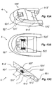
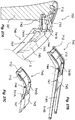
- Figure 1C schematically shows sole parts 3 with a rear sole portion 4 (heel portion), a middle sole portion 5 (midfoot portion) and a front sole portion 6 (forefoot portion).
- the angles ⁇ ⁇ 180 ° between the rear sole portion 4 and the middle sole portion 5 and ⁇ ⁇ 180 ° between the middle sole portion 5 and the front sole portion 6 are preferably smaller for the sole shape 12.
- FIGS. 2A-2D and 3A-3D show systems that have proven to be particularly advantageous in the context of the present invention.
- FIGS. 2A and 2B show a sole member with a fastener 20 for attaching exchangeable heels.
- the fastener 20 is provided on the rear sole portion 4 and preferably has one or more projections 21 having a profile 22.
- the projections 21 and / or the profile 22 preferably run parallel to the plane E of the rear sole portion and in the sole longitudinal direction.
- FIGS. 2C and 2D show a first type of exchangeable paragraphs.
- the shoulder 30 preferably has at its upper side 35 a groove 32 which has a contour which is formed in correspondence with the profile 22 of the rear sole portion 4.
- the profile 22 and the groove 32 are therefore formed so that they interlock and a fall of the heel during lifting of the shoe is prevented.
- the profile is preferably wider than an overlying part of the projection (undercut).
- the profile 22 or the contour of the groove may for example have a dovetail, T or L shape.
- the projection 21 is in FIGS. 2A and 2B shown for illustrative purposes only with an L-profile 22.
- the groove 32 extends parallel to the top 35 and in the sole longitudinal direction. It is open in the longitudinal direction of the sole forward, so that the paragraph 30 in the direction of arrow D (in the longitudinal direction of the sole forward) can be pushed onto the rear sole portion 4.
- the heel and / or shoe may further include a locking system (not shown) that locks the heel upon reaching a defined position. The locking system preferably counteracts a movement of the mounted paragraph to the rear. Different locking systems are described in more detail below.
- FIGS. 3A and 3B show a sole member with a fastener 20 'according to another embodiment of the invention.
- the fastening means 20 ' is provided on the rear sole portion 4 and has a projection 21' with a profile 22 'which preferably extends along the lower end of the projection 21'.
- the profile 22 ' extends obliquely to the plane E of the rear sole portion 4 and preferably away from the plane E and down.
- the profile 22 ' preferably extends along a first imaginary line or straight line G that forms an angle of 70 °> ⁇ > 20 ° with the plane of the rear sole portion E.
- the angle is preferably in a plane that is perpendicular to the plane E of the rear sole portion 4 and extends in the longitudinal direction of the sole.
- the projection 21 ' may have a substantially trapezoidal shape.
- Figures 3C and 3D provide a replaceable shoulder 30 'for the fastener 20' FIGS. 3A and 3B
- the shoulders have a recess 31 'which extends from an elongated opening 34' on the top 35 'of the heel 30' into the shoulder.
- the recess 31 ' preferably has along a second imaginary line or straight line H a substantially constant contour 32', which is formed in correspondence with the profile 22 'of the fastening means 20'.
- the contour 32 ' extends along the second imaginary straight line H, which preferably extends at an angle of 20 ° ⁇ ⁇ 70 ° to the shoulder longitudinal axis F, when the shoulder 30' is viewed from the side (see Figure 3D ).
- the straight line H is preferably in a plane which is parallel to the shoulder longitudinal axis and the sole longitudinal direction.
- the straight lines G and H preferably coincide when the shoulder 30 'is mounted on the rear sole portion 4. The shoulder 30 'can therefore be pushed along the straight line G or H in the sole longitudinal direction to the rear (direction K) on the fastening means 20'.
- the contour 32 ' is preferably formed so that the recess 31' provides a plane which interacts with the profile 22 'to prevent downward descent of the heel (eg, when the shoe is raised).
- the plane therefore preferably points downwards in the longitudinal direction of the sole and downwards in the longitudinal direction of the heel, the normal vector of the plane pointing into the free space of the recess being directed in the longitudinal direction of the sole to the rear and in the longitudinal direction of the heel. If the recess is viewed in a section which runs parallel to the shoulder longitudinal axis F and transversely to the sole longitudinal direction, the contour 32 'is preferably wider than an overlying region of the recess 31'.
- the recess 31 ' is preferably located in the interior of the shoulder 30' and is only open to the top 35 '.
- the recess 31' in its front end region eg on a front wall
- the recess 31' in its front end region (eg on a front wall) preferably provides a stop 33 'to which the projection of the fastening means 21' can butt when the latter
- the heel is completely pushed onto the back sole area.
- the subsequent loading of the rear sole portion 4 in the longitudinal direction F of the heel downwards eg due to the weight of the wearer or wearer therefore results in a self-reinforcing positive fit.
- the rear sole portion 4 and / or the heel may further comprise a lock, which may be, for example, mechanical or magnetic.
- a lock which may be, for example, mechanical or magnetic.
- the rear Sole section 4 for example, have a projection which is provided or formed so that it engages in a recess in the top 35 'of the paragraph 30' or adjacent to the front of the paragraph when the shoulder 30 'is completely pushed.
- a projection on the upper side 35 ' may be provided or formed so that it engages in a recess which is formed on the underside of the rear sole portion 4.
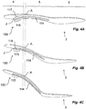
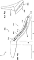
- FIGS. 4A to 4C schematically illustrate a first embodiment of the first mechanism 100 for adjusting the sole curvature in the first transition region A of a sole member 3.
- the mechanism 100 has a stiffening element 114. This is stiffer than the first transition region A, wherein the flexibility of the sole member may result, for example, from the properties of the materials used or due to the use of a hinge in the first transition region.
- the sole part may have a first joint in the first transition region A and a second joint in the second transition region B. The first joint may extend along the first transition region A and the second joint along the second transition region B.
- the stiffening element 114 extends along the rear sole section 4 and the middle sole section 5. Along the middle sole section 5, the stiffening element 114 is at least partially firmly connected to the sole part 3.
- the stiffening element 114 may have a substantially flat, elongated structure in this area.
- a rear portion 115 of the stiffening member 114 extends along the rear sole portion 4, but is not connected or fixed to the rear sole portion 4.
- the distance between the rear sole portion 4 and the rear portion 115, in particular the angle therebetween, can therefore be varied, as in FIG Figures 4A-4C shown.
- the curvature in the first transition region A is smaller as the angle between the rear part 115 and the rear sole portion 4 increases. If the angle is smaller, the sole curvature increases ( FIG. 4B ).
- the sole curve in the first transition region A is therefore smaller when the rear part 115 of the first stiffening element 114 is further spaced from the rear sole portion 4.
- the curvature in the first transition region A can therefore be changed according to the heel height, with a continuous adjustment is possible.
- the rear portion 115 of the stiffening member 114 may abut or be spaced from the rear sole portion 4 in a neutral state of the first mechanism.
- the paragraphs according to the invention may be designed so that the stiffening element 114 is pressed or pushed away from the rear sole section when the heel is fastened.
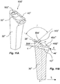
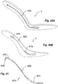
- FIGS. 5A and 5B is shown cut laterally and along the sole longitudinal direction, the shoulder 30 "a structure 41" on to push away the stiffening element 114 from the bottom of the rear sole portion.
- the structure 41 is preferably formed by an opening 43" which extends from the top 35 "in the longitudinal direction of the sole back and in paragraph longitudinal direction F down in the paragraph 30" and is open in the longitudinal direction of the sole forward.
- the opening 43 “receives the rear portion 115 of the stiffening member 114 when the heel 30" is pushed onto the rear sole portion 4.
- the shoulder 30 may also be configured for use with any of the attachment systems 20, 20 'described above, particularly for use with the attachment system 20.
- the shoulder 30 may therefore include, for example, one or more of the grooves 32 described above.
- FIGS. 5A and 5B are designed such that the opening 43 "tapers in the insertion direction of the rear part 115 or becomes increasingly narrower FIG. 5E (perspective view), FIG. 5F (First sectional plane parallel to the paragraph longitudinal direction F and Sohlenlteilscardi L) and FIG. 5G (second cutting plane transverse to the first cutting plane and parallel to the insertion direction E) of paragraph 30 " shown.
- FIG. 5E perspective view
- FIG. 5F First sectional plane parallel to the paragraph longitudinal direction F and Sohlenlnaturesraum L
- FIG. 5G second cutting plane transverse to the first cutting plane and parallel to the insertion direction E
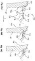
- the shoulder 30 " may have an opening 43" which in a first sectional plane parallel to the heel longitudinal direction F of the inlet opening 44 ", through which the rear part 115 of the stiffening element (not shown) in the opening 43" can be inserted accordingly an angle ⁇ in the direction of insertion E tapers.
- the opening 43 " can be designed so that it lies in a second cutting plane, which is transverse to the first cutting plane and parallel to the insertion direction E (see FIG. 5G ) Tapers from the inlet opening 44 "in the insertion direction E in accordance with an angle ⁇ .
- the opening 43" may be designed tapering in several cutting planes, for example in section along the shoulder longitudinal direction F (FIG. FIG. 5F ) and in section along the insertion direction E (see FIG. 5G ). Furthermore, in FIGS. 5E to 5G can be seen, the opening 43 "for the rear part 115 of the stiffening element 114, which forms with the top 35" of the paragraph 30 "the wedge-shaped structure 41" (see FIG.
- the projecting structure 45 may have an upper slope 48A "having an angle ⁇ of 20 ° to 70 °, 30 ° to 60 ° or 40 ° to 50 ° with the top 35 "can form.
- the protruding structure 45 may have a phased or inclined end stop surface 48B" that may extend substantially parallel (eg, at a maximum deviation of ⁇ 1 °, ⁇ 3 °, or ⁇ 5 °) from the top 35 ".
- the upper slope 48A “and / or the end stop surface 48B” may be formed to contact the sole portion when the heel 30 "is secured to the sole portion.
- a projecting structure 45 "according to Figures 5E and 5F Can be used in combination with a tapered opening 43 ", but also independently.
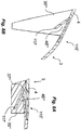
- Figures 5H and 5J show a variant of the first stiffening element 114 on a sole part 3 shown schematically.
- the variant can be used with different paragraphs according to the present invention, provides in connection with the paragraph variants of FIGS. 5E to 5G and 11A to 12C (see below) but special advantages.
- the stiffener 114 is formed by two rails 114A and 114B, although only one rail or more than two rails may be used.
- the rails 114A, 114B extend along the middle sole portion 5 with the sole not shown in the middle sole portion 5 for ease of illustration of the rails 114A and 114B.
- the rails 114A and 114B may be made of a flat steel, for example.
- the rails 114A and 114B provide a first hinge 601, via which the rear sole portion 4 is movably secured thereto, and a second hinge 602, via which the front sole portion 6 is movably secured thereto.
- the rails 114A and 114B may each have a first bore for receiving an axis of the first hinge 601 and a second bore for receiving an axis of the second hinge 602.
- the rails 114A and 114B are arranged in the illustrated embodiment, substantially parallel or slightly tapered.
- the rear portions 115A and 115B of the rails 114A and 114B may converge rearward in the sole longitudinal direction (eg, at the angle ⁇ ).
- the stiffener 114 which is commonly formed by both rails 114A and 114B, therefore becomes narrower.
- the rear part 115A and 115B in FIG.
- each stiffening element 114A, 114B itself become narrower (eg at the angle ⁇ ). Together with the tapered opening 43 "can thus be achieved in spite of any manufacturing tolerances a substantially backlash-free attachment of different heels on the sole part 3.
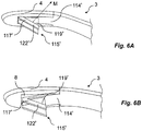
- the first stiffening element 114 ' accordinging to a second embodiment of the invention in the region of its rear part 115' has a projection 117 '.
- the projection 117 'in the example shown extends downwards from the stiffening element 114' and provides a surface 119 'which extends substantially in the transverse direction of the sole part 3 and extends obliquely to the plane of the rear sole portion 4.
- the surface 119 ' preferably forms an angle 70 °> ⁇ > 20 ° with the plane of the rear sole portion E, wherein the angle is preferably in a plane which is perpendicular to the plane E of the rear sole portion 4 and extends in the longitudinal direction of the sole.
- the normal vector M of the surface 119 ', which points away from the projection 117' preferably points upwards in the sole longitudinal direction and upwards in the longitudinal direction of the heel.
- the projection 117 ' corresponds to the projection 21' of the fastening means 20 'described above with reference to FIGS. 3A and 3B is described.
- the surface 119 ' may be formed by a profile 122', which corresponds to the profile 22 'of the fastener 20' and is also shaped.
- the fastening means 20 'can therefore be provided on the stiffening element 114', wherein the projection 117 'can be used simultaneously for adjusting the first mechanism 100 and for securing the heel to the shoe.
- the projection 117 ' may also be provided in combination with an additional fastening means, for example the fastening means 20' of FIGS. 3A and 3B ,
- the additional fastening means may be provided, for example, on the rear sole part 4.
- the middle sole portion 4 may have a recess 8 for receiving the rear part of the stiffening element 114 '.
- stiffening element 114 ' is in Figures 6A and 6B shown integrally with the middle sole portion 5. However, even in this embodiment of the invention, various elements and materials may be used for the stiffener 114 'and the middle sole portion 5 (see FIG Figures 4A-4C ).
- Figures 7A-7H show another type of exchangeable paragraphs according to embodiments of the invention. These are in particular when used with the stiffening element 114 'after Figures 6A and 6B advantageous.
- the shoulders 30 "' have a structure 46"' for urging the stiffening element 114 'away from the underside of the rear sole portion.
- the structure 46 '" is preferably formed by an opening 47"' extending from the top 35 "'in the longitudinal direction of the sole forward and in paragraph longitudinal direction F down in the paragraph 30"'.
- the opening 47 "' is preferably provided so that it receives the profile 122' of the stiffening element 114 'when the shoulder 30'" is pushed onto the rear sole portion.
- the structure 46 '" is preferably wedge-shaped, with the tapered end of the wedge-shaped structure being directed rearward in the longitudinal direction of the sole Heel may be the opening 47 '' steeper ( Figures 7A-7D ) or flatter ( Figures 7E-7H ).
- the shoulders 30 "'when cut along the sole longitudinal direction have at least one surface 49"' formed by the opening 47 "' the normal vector O of the surface 49 "', which points into the free space of the opening 47"', points in the longitudinal direction of the sole to the rear and in the longitudinal direction of the heel downwards.
- the recess 31 "'has a contour which is wider in a lower area than in an upper area.
- paragraphs 30 '" may, depending on the height also have a recess 37"', which is provided for receiving the depressed rear portion of the stiffening element 114 '(see Figures 7E and 7G ).
- the shoulders 30 '' may also have one or more recesses 31 '' for an additional fastening means (eg a fastening means 20 '), for example directly can be provided on the rear sole portion.
- an additional fastening means eg a fastening means 20 '
- Figures 8A and 8B show a sole part 3 with a high or a flat shoulder 30 "'.
- the rear part 115' of the stiffening element will be further or less far from the rear sole portion 4.
- the stiffening element can be received in the recess 37 '' of the paragraph.
- the sole parts and / or heels according to the invention can be provided with a locking system for locking different heels on the sole part.
- a projection is preferably provided on the heel or on the sole part, with a recess or recess being provided on the other of these two elements (i.e.
- FIGS. 5C and 5D A first embodiment of a locking system 500 according to the invention is shown schematically in FIGS. 5C and 5D (in conjunction with a first mechanism according to the first embodiment) and Figures 9A, 9B, 10A and 10B (in conjunction with a first mechanism according to the second embodiment).
- the locking system 500 is provided via a recess 501 on the rear sole portion 4, which is provided so that a projection 502 engages the shoulder in the recess 501 when the heel is completely pushed onto the sole member.
- Figures 9A, 9B, 10A and 10B show that the arrangement of the recess 501 and the projection 502 can also be reversed, so that the recess 501 is provided on the shoulder and the projection 502 on the sole part.
- the locking of the locking system 500 can be solved in both cases by the rear sole portion 4 is raised. This embodiment is therefore particularly advantageous when the heel is pushed by the fastening means or by the first stiffening element to the rear sole portion.
- Figures 11A, 11B and 12A to 12C show paragraphs with a locking system 500 'according to a second embodiment.
- the shoulder 30 "has on its upper side 35" a recess in which a locking element in the form of a protruding hook 502 'is arranged.
- the hook 502 ' hereby provides an undercut which forms a recess 506', which is open in the longitudinal direction L of the sole longitudinally.
- the hook 502' On the rear side opposite the recess 506 ', the hook 502' has an inclined surface 504 ', which is arranged at an angle ⁇ to the base of the recess on the upper side 35 ", the angle ⁇ can here be the angle ⁇ between the oblique surface
- the angle ⁇ may be about 90 ° to 150 °, about 91 ° to 120 °, or about 95 ° to 110 °.
- FIGS. 13A to 13C show a rear sole member 4 with a recess 501 'for receiving the hook 502' of paragraphs 30 "of FIGS. 11A to 12C
- the recess 501 ' has a deflectable latching element 521' (eg in the form of a hollow tube), which is deflected forward in the longitudinal direction of the sole when inserting the hook 502 'against the force of the springs 523' and into the recess 506 'of the Hooks 502 'engages when the heel 30 "is completely pushed onto the sole part, thereby locking the heel 30" to the rear sole part 4.
- a deflectable latching element 521' eg in the form of a hollow tube
- first abutment surface is adapted to abut the bottom of the recess at the top 35 "of the shoulder 30" when the shoulder 30 "is mounted to the sole portion
- second abutment surface 512 ' preferably arranged at an angle ⁇ to the first contact surface 511 'and thus provides a contact surface for the upper inclined 48A "of paragraph 30".
- the angle ⁇ can therefore have an angular extent of 180 ° minus the angle ⁇ between the upper side 35 "and the upper slope 48A”.
- the third abutment surface 513 ' may provide a abutment surface for the end stop 48B ", rubber stoppers may be disposed on this third abutment surface 513' or other abutment surfaces to compensate for manufacturing tolerances between different shoulders.”
- the third abutment surface 513 ' may be substantially parallel to the first abutment surface ,
- the recess 501 ' may further include a wall 507' disposed at an angle ⁇ to the first abutment surface 511 'and providing a bearing surface for the inclined surface 504' of the hook 502 '.
- the angle ⁇ can therefore have an angular extent of 180 ° minus the angle ⁇ between the top 35 "and the sloping surface 504 'of the hook 502'
- the measure of the angles ⁇ and ⁇ is preferably different.
- a contact surface 514 ' can also be provided. This can run substantially parallel to the first contact surface 511 ', but is preferably not arranged in the same plane as this.
- the fourth contact surface 514 ' may extend in a U-shape around the first contact surface 511', the second contact surface 512 'and / or the third contact surface 513'.
- the rear portion 115 of the first stiffening element is first inserted into the opening 43 "of the shoulder 30" in order to lock the shoulder 30 "on the rear sole portion 4 ( Figure 14A ).
- the rear sole portion 4 is then pivoted to insert the hook 502 'in the recess 501', which deflects the locking element 521 'against the force of the springs 523' ( Figure 14B ).
- Upon reaching the end position of paragraph 30 "on the sole part ( Figure 14C ) snaps the locking element 521 'then in the recess 506', whereby the paragraph 30 "is locked.
- FIG. 15 shows a mechanism according to the invention 530 'for releasing the locking of a paragraph (not shown) of the sole part (only partially shown).
- the mechanism is here for better illustration in connection with the locking system of FIGS. 11A to 14C but not limited thereto.
- the latching element 521' can be deflected against the force of the springs 523 'until the latching element 521' leaves the recess 506 '(see FIG FIGS. 14A to 14C ) is moved out.
- the engagement between the hook 502 'and the locking element 521' is thereby released so that the heel can be removed from the sole part.
- the mechanism 530 ' has an actuator 531' that can be grasped by the user and thus provide an interface therefor.
- the actuating element 531 ' is designed as a lever. This is rotatably mounted on the sole part, for example on the first stiffening element 114.
- the lever may for example be arranged between two rails 114A and 114B, which form the stiffening element 114.
- Mechanism 530 ' is not limited to this.
- the actuating element 531 ' is mechanically coupled to the latching element 521'. This is in the exemplary embodiment of FIG. 15 by means of a lance or wire 535 '(e.g., a plastic cord such as a nylon cord) extending from the actuator 531' to the latch member 521 'and back again.
- a lance or wire 535 ' e.g., a plastic cord such as a nylon cord
- a tensile force is exerted, which is transmitted from the cord to the latching element 521' and deflects it.
- the protruding structure 45 "of the shoulder 30" in a plan view of the upper side 35 assumees substantially the shape of a T.
- a web 48C" extending from the bottom surface of the recess on the upper side 35 "of FIG A portion 48D "between the left and right toe tips of the T-shaped structure may be recessed leaving one horn at each of the right and left toe upper slope 48A "and the end stop surface 48B".
- the T-shaped structure can be arranged completely within the recess on the upper side 35 ", as in the exemplary embodiment of FIGS. 12A to 12C is shown.
- Figures 16A and 16B show a first embodiment of a second mechanism 300 for adjusting the second transition region B between the middle sole portion 5 and the front sole portion 6.
- the mechanism 300 includes a slidable stiffening element 302 that extends along the sole longitudinal direction from a first position (FIG. FIG. 16A ), which causes a first sole curve in the transition region B, in a second position ( Figure 16B ), which causes a second sole curve in the transition region B.
- first sole curve differs from the second sole curve.
- the sole part 3 is preferably made more flexible than the stiffening element 302 in the transition region B.
- the transition region B can be articulated (see, for example, FIG Figures 5H and 5J ) and / or more flexibly than the rear, the middle and / or the front sole portion 4, 5, 6 be designed.
- the stiffening element 302 preferably does not protrude into the transition area 13 and / or into the front sole section 6.
- the sole curvature in the transition area B therefore corresponds to the curvature with which the sole part 3 was manufactured.
- the stiffening element 302 is preferably also guided in the region of the central sole portion in a guide 306. This is formed in the example shown as a rail.
- the guide 306 retains the stiffener 302 at the middle sole portion 5 as the stiffener 302 advances and extends into the transition region B. Thus, buckling or bending of the stiffening element 302 along the middle sole portion is prevented.
- the second mechanism also has, according to the illustrated embodiment of the invention, a Bowden cable 310 with a Bowden cable core 312 and a Bowden cable housing 314.
- the Bowden cable core 312 extends from the rear sole portion 4 to the stiffening element 302 and is firmly connected thereto. A displacement of the Bowden cable core 312 therefore leads to a displacement of the stiffening element 302.
- the stiffening element 302 can be displaced between the first and the second position by actuation of the transmission element (Bowden cable core 312).
- the transfer member is preferably actuated upon placement and / or removal of the heel.
- a driver 316 is provided at the rear end of the Bowden cable core 312, which interacts with exchangeable heels to allow an adjustment of the movement device when placing and / or removing the heel.
- the driver 316 is fixedly connected to the Bowden cable core 312.
- the bowden sheath 314 may be attached to the sole portion 3 and / or the first stiffener 114, wherein the Bowden cable may extend through the recess of the first stiffener (see Figures 16A and 16B ).
- the second mechanism after Figures 16A and 16B can be used with different first stiffening elements 114, 114 '.
- paragraphs 330, 330 'according to the invention at its upper side 335, 335' have a recess 360, 360 ', which is provided or formed so that when attaching the paragraph on the sole part with an element of the second mechanism according to the embodiment of Figures 16A and 16B interacts or avoids an interaction.
- paragraph 330 of Figure 17A an elongated recess 360, which is designed so that there is no displacement of the driver 316 when pushing and pulling the shoulder 330 on the rear sole portion 4.
- the recess is therefore designed so that the driver 316 is not contacted.
- the longer dimension of the recess 360 preferably extends in the longitudinal direction of the sole, wherein the recess may extend approximately 20 to 30 mm in this direction (length of the recess).
- the recess 360 ' is shorter (for example at most 5 mm or at most 10 mm long) and has approximately the shape of the driver 316.
- the driver 316 is received in the recess 360' when the shoulder 306 'is slid on and secured to the Paragraph 306 ', which results in an adjustment of the mechanism 300.
- the recess 360 ' is designed so that the carrier is moved forward when the shoulder 330' is pushed from back to front onto the rear sole portion 4.
- the shape of the sole part of FIG. 16A therefore changes to that of Figure 16B ,
- Figures 18A-19C show a further second mechanism 400 for adjusting the second transition region B according to another embodiment of the invention in various positions from the side and from the rear.
- the mechanism 400 has a rotatable stiffening element 402, which in the illustrated example is designed as an elongated shaft.
- the stiffening element 402 extends from the middle sole section 5 into the transition region B and preferably also into the front sole section 6 and / or the rear sole section 4.
- the second stiffening element 402 has a curved segment 403, which has a predetermined, defined curvature and extends at least in the transition region B.
- a front end segment 404 of the stiffening element 402. This is preferably received in the region of the front sole portion 6 in a recess 407 which allows movement of the end segment 404 in the plane of the front sole portion 6.
- the stiffening element 402 is rotatably mounted in the region of the middle sole portion 5 and / or the rear sole portion 4.
- a first angle of rotation (FIG. Figures 18A and 19A ) in a second angle of rotation ( Figures 18B . 19B and 19C
- the second sole curve is larger in this case than the first.
- the curved portion 403 of the stiffening element 402 preferably tensions a mental curvature plane, in which the radius of curvature also lies.
- This curvature plane may be perpendicular to the plane of the front sole portion 6 when the stiffener 402 is twisted to the second angle of rotation (see FIG Figure 19C ).
- the rotation of the stiffening element 402 further causes the front end segment 404 to protrude into the recess 407 to different degrees.
- the stiffening element 402 may further comprise a lever 416, over which the stiffening element 402 is twisted.
- the lever 416 is preferably provided in the region of the rear sole portion 4.
- Figures 19A-19C show the sole part 3 from behind, wherein the stiffening element 402 is shown in different angles of rotation. Due to the pivoting of the curved region 402, these cause different sole curvatures in the transition region B.
- Figures 20A and 20B show by way of example various possibilities for the rotatable mounting of the stiffening element 402.
- the stiffening element 402 in a recess of the sole part ( Figure 20A ) or in a holding device, for example the sleeves (eg brass tubes) of Figure 20B which are preferably fixedly connected to the sole part 3 (eg by gluing, welding, soldering, etc.) are stored.
- the holding device can also prevent an axial displacement of the second stiffening element in the longitudinal direction of the sole.
- the lever 416 and / or the curved segment 403 may be formed by sliding a sleeve (eg, a brass tube) over the rear end portion of the second stiffener 402 and bending it along with it.
- a sleeve eg, a brass tube
- Figures 22A-22D show paragraphs of different heights 330, 330 ', 330 "with a recess 360, 360', 360", with the lever 416 of the stiffening element 402 of the second mechanism after Figures 18A-19C interacts.
- the contour of the recess 360, 360 ', 360 is in particular provided so that the recess in the attachment of the paragraph 330, 330', 330" interacts with the lever 416 on the sole part 3.
- the recess 360, 360 For adjusting the lever 416, the recess 360, 360 “according to one embodiment, a surface 361, 361", which is in a section of the paragraph, which is parallel to the paragraph longitudinal axis and transverse to the sole longitudinal direction, obliquely to the longitudinal direction of paragraph F ( Figure 22D ).
- the surface 361, 361 “contacts the lever 416 when the heel is pushed onto the sole member so that the lever 416 is rotated in accordance with the slope of the surface 361, 361".
- recess or groove 360, 360 ', 360 can rotate along the sole or groove longitudinal direction, depending on the heel height, the groove can be twisted differently, so that it slides when pushed on the paragraph comes on the rear sole portion 4 to the desired rotation of the lever (see Figures 23A, 23B and 23C , where in each case the achieved rotation of the lever is shown).
- the groove 360, 360 "preferably twists successively in the sole longitudinal direction and assumes different angles to the shoulder longitudinal axis in different sections running parallel to the longitudinal direction of the shoulder, for example, the groove 360 extends in the region of an inlet opening through which the lever 416 extends into the groove can occur, substantially parallel to the paragraph longitudinal direction F (see Figure 23D ), in a first section, which runs parallel to the paragraph longitudinal direction F, at an angle ⁇ 1 to the paragraph longitudinal direction F (see Figure 23E ) and in a second section which is also parallel to the heel longitudinal direction F, but is further away from the entrance opening of the groove 360 than the first cut, at an angle ⁇ 2 > ⁇ 1 to the shoulder longitudinal axis F (see Figure 23F ).
- the lever 416 is therefore when pushing the paragraph as shown by Figures 23A-23C adjusted.
- paragraphs 330, 330 ', 330 include grooves 32 for a fastener 20 on the rear sole portion 4. It should be understood, however, that the other fastening means described above may be used as well (e.g., the fastener 20', in which Figs The angle of the surface 361, 361 "to the top of the heel 335, 335" in this case, preferably flat in the longitudinal direction of the sole to the front.
- Figures 24A and 24B show a modification of the second mechanism 400 'according to FIGS. 18A to 21 on a sole part 3.
- the sole part is in this case arranged in a position for a flat heel ( Figure 24A ) and in a high-heel order ( Figure 24B ).
- the second stiffening element 402 'of Figures 24A and 24B has a first curved or angled segment 403 'in the second transition region B and a second curved or angled segment 405' in the first transition region A.
- the front end region 404 'of the second reinforcing element 402' is movable in the front sole section 6 and the rear end region 406 'movably received in the rear sole portion 4.
- the front sole portion 6 has a recess 407 'for receiving the front end portion 404' and the rear sole portion 4 has a recess 408 'for receiving the rear end portion 406'.
- a second stiffening element 402 ' accordinging to Figures 24A and 24B the sole curve is coupled in the first transition region A with the sole curve in the second transition region B.
- the adjustment of the sole curvature in the first transitional region A can lead to a rotation of the reinforcing element 402 'via the second curved or angled section 405', which in turn via the pivoting of the second curved or angled section 403 'to a change of the sole curvature in the second transition region B leads.
- the sole curvature in the first transition region A therefore requires the sole curvature in the second transition region B (and vice versa).
- FIGs 25A and 25B show a sole member 3 with a dressing aid 700 according to the invention, which allows a temporary attachment of a paragraph on the sole member 3, before it is locked.
- the dressing aid 700 according to the invention can also be used without a further locking system on the sole part 3.
- Figures 25A and 25B only the front sole portion 6 and the middle sole portion 5 are shown, it being understood by those skilled in the art that the sole portion 3 may also have a rear sole portion.
- the dressing aid 700 comprises in the case of the embodiment of Figures 25A and 25B a cantilever arm 710 extending rearward from the middle sole portion 5 in the longitudinal direction L of the sole. On arm 710, a locking projection 712 is provided, which is provided for engagement in a corresponding recess of a paragraph.
- the cantilever arm 710 is preferably not rigid, but designed so that it is elastically deflected when attaching a paragraph.
- the cantilevered arm 710 may be provided in the region of the rear part of the first stiffening element. Thereby, the cantilevered arm 710 can preferably be inserted into the same recess of the heel as the rear part of the first stiffening element.
- the cantilever arm 710 is arranged between the rear part 115A of a first rail and the rear part 115B of a second rail, which together form the first stiffening element.
- the cantilever arm 710 is movable relative to the rear part 115A, 115B of the first stiffening element.
- Figures 26A to 26C show a sequence illustrating the provisional attachment of a paragraph on the sole part by means of the dressing aid 700.
- the figures here show a paragraph 30 ", however, inventive dressing aids can also be used with the other paragraph types according to the present invention.
- the shoulder 30 has an opening 720 for receiving the cantilever arm 710, which may optionally be the opening 43" for receiving the rear part 115 of the first stiffening element (see FIG Figure 26A ).
- the cantilever arm 710 is deflected when attaching the paragraph 30 "on the rear part 115 downward (see Figure 26B ) and, upon reaching an undercut 721 in the opening 720 engages with the undercut 721, so that a renewed removal of the heel 30 "from the rear part 115 is counteracted (see Figure 26C ).
- the undercut 721 is provided on the upper ceiling 723 of the opening 720.
- FIGS. 27A to 27C show a mechanism 740 for releasing the tightening aid 700, which allows the decoupling of the locking projection 712 of the undercut 721 (see. Figure 26A ) and thus the removal of the paragraph 30 "allowed by the sole part.
- the mechanism 740 has two levers 741A and 741B that act on an end portion 742 of the cantilevered arm 710 to deflect the cantilever arm 710. At its other end region 743, the levers 741A and 741B are coupled to a user interface 745.
- the operation of the user interface 745 (which is formed in the illustrated embodiment as a lever which can be pivoted about a pivot point 747) is transmitted via the lever 741A and 741B on the cantilever arm 710, whereby this is deflected (in the illustrated embodiment in Paragraph longitudinal direction down).
- the pivoting of the user interface 745 about the pivot point 747 therefore leads to the deflection of the latching projection 712 downwards, which is thereby decoupled from the undercut 721.
- the levers 741A and 741B and / or the user interface may be rotatably supported via the first stiffener element, which is exemplified herein by two rails 114A and 114B.
- the levers 741A and 741B and / or the user interface 745 can be arranged between the rails 114A and 114B. Further, it is optionally possible to form the levers 741A and 741B curved, whereby a particularly space-saving arrangement of the lever can be achieved.
- a single lever or more than two levers can be provided, provided that they fulfill a corresponding functionality.
- the tightening aid 700 can also be designed such that after loosening a re-snapping of the cantilevered arm 710 with the undercut 721 is prevented.
- a bevel 725 or 726 may be provided in the opening 720 and / or on the cantilevered arm 710 (cf. Figure 26A ), which when deflecting the cantilevered arm 710 when loosening the donning aid 700 leads to a displacement of the heel in the longitudinal direction of the sole L to the rear. As a result, the cantilever arm 710 can no longer engage the undercut 721 of the shoulder.
- FIGS. 28A to 28E show a sequence that the release of the dressing aid by means of the mechanism 740 of FIGS. 27A to 27C shows.
- the latching projection 712 is deflected by means of the lever 741, which is actuated via the user interface 745.
- the self-supporting arm 710 slides over the slope 725 (see Figures 28B and 28C ), resulting in a relative movement between the shoulder 30 "and the sole part (not shown) on which the mechanism 740 is provided, the locking projection 712 can therefore no longer engage in the recess 721 when the user interface 745 is released, and the cantilever arm 710 snaps back (see FIG. 28D ).
- the dressing aid does not hinder the removal of the heel 30 "so that it can be removed from the sole part (see Figure 28E ).
- the user interface 745 and the actuator 531 'of the locking system release mechanism 500' may be formed as a single component (eg, as a single lever).
- the invention therefore discloses improved mechanisms that ensure optimum adjustment of the sole shape regardless of the heel height of a replaceable heel. Furthermore, improved fastening systems are disclosed which allow a simple and secure attachment of exchangeable heels on the shoe sole. The shoes according to the invention can therefore be adapted to the situation, whereby the user is provided with a full-fledged shoe independently of the heel height.
- Aspect 1 Sole piece (3) for a shoe for use with different heels, the sole piece (3) having a front (6), a middle (5) and a back sole portion (4); said sole member (3) having a sole curvature adjustment mechanism (100) in a transition region (A) between said middle sole portion (5) and said rear sole portion (4); wherein the mechanism (100) comprises a stiffening element (114, 114 ').
- Aspect 2 Sole part (3) according to aspect 1 or la, wherein the stiffening element is stiffer than the transition region (A) of the sole part (3).
- Aspect 3 Sole part (3) according to one of the preceding aspects, wherein the transition region (A) is more flexible than the rear sole portion (4) and / or the middle sole portion (5).
- Aspect 4 Sole part (3) according to aspect 3, wherein the transition region (A) has a joint (601).
- Aspect 5 Sole part (3) according to aspect 4, wherein the middle sole portion (5) along a rotation axis is pivotable to the rear sole portion (4), wherein the axis of rotation preferably extends transversely to the sole longitudinal direction.
- Aspect 6 Sole part (3) according to any one of the preceding aspects, wherein the sole part (3) has a leaf spring which is fixedly connected to the rear sole portion (4) and the middle sole portion (5).
- Aspect 7 Sole part (3) according to any one of the preceding aspects, wherein the stiffening element (114, 114 ') has a front part which extends in the region of the middle sole portion (5) and / or is fixedly connected to the middle sole portion (5).
- Aspect 8 The sole member (3) according to aspect 7, wherein the front part is integrally formed with the middle sole portion (5).
- Aspect 9 A sole member (3) according to any preceding aspect, wherein the stiffening member (114, 114 ') has a rear portion (115, 115') extending along the rear sole portion (4) and preferably not fixed to the rear sole portion (4) or not connected to the rear sole portion (4).
- Aspect 10 Sole part (3) according to one of the preceding aspects, wherein an angle and / or a distance between a rear part (115, 115 ') of the stiffening element (1 14, 114') and the rear sole portion (4) is adjustable.
- Aspect 11 The sole member (3) according to aspect 10, wherein the reduction in the distance between the rear part (115, 115 ') and the rear sole portion (4) results in an increase of the curvature in the transition area (A).
- Aspect 12 Sole part (3) according to aspects 10 or 11, wherein an increase in the angle or the distance between the rear part (115, 115 ') and the rear sole portion (4) leads to a reduction of the curvature in the transition region (A).
- Aspect 13 Sole part (3) according to aspects 9 to 12, wherein the rear part (115, 115 ') extends under the rear sole portion (4).
- Aspect 14 A sole member (3) according to any one of the preceding aspects, wherein the stiffening member (114, 114 ') along a rear part (115, 115') is loose from the rear sole portion (4).
- Aspect 15 Sole part (3) according to one of the preceding aspects, wherein the stiffening element (114, 114 ') from the sole part (3), in particular a rear part (115, 115') from the rear sole portion (4) wegdrückbar.
- Aspect 16 Sole part (3) according to aspect 15, wherein the rear part of the stiffening element by means of a wedge-shaped structure (41 ", 46"') on a shoulder which can be pushed between the stiffening element (114, 114') and the rear sole portion (4) , wegdrückbar from the rear sole portion (4).
- Aspect 17 Sole part (3) according to aspects 9 to 16, wherein the rear part (115, 115 ') is at a neutral position without a step spaced from the rear sole portion (4), wherein the distance between the rear part (115, 115') and the rear Sole section (4) preferably increases in the longitudinal direction of the sole to the rear.
- Aspect 18 Sole part (3) according to one of the preceding aspects, wherein the stiffening element (114, 114 ') has a projection (117, 117').
- Aspect 19 Sole part (3) according to aspect 18, wherein the projection (117, 117 ') extends laterally and / or downwardly away from the stiffening element (114, 114').
- Aspect 20 A sole member (3) according to aspects 18 or 19, wherein the projection (117, 117 ') provides at least one surface (119') extending substantially transverse to the sole longitudinal direction.
- Aspect 21 Sole part (3) according to aspects 18, 19 or 20, wherein the projection (117, 117 ') provides at least one surface (119') whose normal vector (M) pointing away from the projection (117, 117 ') in the longitudinal direction of the sole towards the front and / or in the longitudinal direction (F) facing upward.
- Aspect 22 Sole part (3) according to aspects 20 or 21, wherein the surface (119 ') extends obliquely to the plane of the rear sole portion (4).
- Aspect 23 Sole part (3) according to aspects 20, 21 or 22, wherein the surface (119 ') extends in the longitudinal direction of the sole forwardly away from the plane of the rear sole portion (4).
- Aspect 24 Sole part (3) according to aspects 18 to 23, wherein the projection (117, 117 ') for adjusting the mechanism (100) can be used.
- Aspect 25 Sole part (3) according to aspects 18 to 24, wherein the projection (117, 117 ') can be used to attach a heel to the rear sole portion (4).
- Aspect 26 Sole part (3) according to one of the preceding aspects, wherein the stiffening element (114, 114 ') along the middle sole portion (5) is substantially flat and / or elongated.
- Aspect 27 A sole member (3) according to any one of the preceding aspects, wherein said stiffening member (114, 114 ') has a recess through which an element of a second mechanism (300, 400) may extend.
- Aspect 28 Sole part (3) according to one of the preceding aspects, wherein the first stiffening element (114, 114 ') is made of one of the following materials or combinations thereof: steel, metals, metal alloys, plastics, composite materials.
- Aspect 29 Sole part (3) according to one of the preceding aspects, wherein the first stiffening element (114, 114 ') is made of V2A sheet metal.
- Aspect 29a Sole part (3) according to one of the preceding aspects, wherein an angle between the rear part (11, 115 ') of the stiffening element (114, 114') and the middle sole portion (5) when changing the sole curve in the transition region (A) is substantially equal remains.
- Aspect 29b Sole part (3) according to any one of the preceding aspects, wherein the rear sole portion (4) is pivotally attached to the stiffening element (114, 114 ').
- Aspect 29c A sole member (3) according to any one of the preceding aspects, wherein the front sole portion (6) is hinged to the stiffening member (114, 114 ').
- Aspect 29d Sole part (3) according to one of the preceding aspects, wherein the stiffening element (114, 114 ') by several, preferably two, rails (114A, 114B) is formed.
- Aspect 29e Sole part (3) according to one of the preceding aspects, wherein the rear part (115, 115) of the stiffening element (114, 114 ') in the sole longitudinal direction tapers or narrower.
- Aspect 30 Sole piece (3) for a shoe for use with different heels, the sole piece (3) having a front (6), a middle (5) and a back sole portion (4); wherein the sole part (3) has a mechanism (300, 400) for adjusting the sole curvature in a transition region (B) between the front sole portion (6) and the middle sole portion (5): wherein the mechanism (300, 400) comprises a slidable and / or rotatable stiffening member (302, 402) provided such that displacement of the stiffening member (302, 402) changes the sole curvature in the transition region (B) leads.
- Aspect 31 The sole member (3) of aspect 28, wherein the displacement of the stiffening member (302, 402) results in a change in the angle between the front sole portion (6) and the middle sole portion (5).
- Aspect 32 Sole piece (3) for a shoe for use with different heels, the sole piece (3) having a front (6), a middle (5) and a back sole portion (4); the Sole member (3) has a sole curvature adjustment mechanism (300) in a transition region (B) between the front sole portion (6) and the middle sole portion (5); the Mechanism (300) comprises a displaceable stiffening element (302) adapted to be displaced along the sole longitudinal direction from a first position causing a first sole curve in the transition region (B) to a second position causes a second Sohlenenkrümmung in the transition region (B).
- Aspect 33 The sole member (3) of aspect 32, wherein the first sole curve is different from the second sole curve.
- Aspect 34 Sole part (3) according to aspect 32 or 33, wherein the stiffening element (302) is formed as an elongate stiffening sheet.
- Aspect 35 Sole part (3) according to aspect 32, 33, or 34, wherein the stiffening element (302) in the region of the middle sole portion (5) at least partially guided in a guide (306).
- Aspect 36 Sole part (3) according to aspects 32 to 35, wherein the guide (306) is fixedly connected to the sole part (3).
- Aspect 37 Sole part (3) according to aspect 36, wherein the guide (306) is fixedly connected to the middle sole portion (5).
- Aspect 38 Sole part (3) according to aspects 35, 36 or 37, wherein the guide (306) hinders kinking and / or bending of the stiffening element (302) in the front region of the middle sole portion (5) and / or in the transition region (B).
- Aspect 39 Sole part (3) according to aspects 32 to 38, wherein the stiffening element (302) in the first position does not protrude into the front sole portion (6).
- Aspect 40 Sole part (3) according to aspects 32 to 39, wherein the sole curvature in the transition region (B) corresponds in the first position of the sole curve, with which the sole part (3) has been made.
- Aspect 41 Sole part (3) according to aspects 32 to 40, wherein the stiffening element (302) protrudes into the transition region (B) and / or in the front sole portion (6) when it is moved to the second position.
- Aspect 42 Sole part (3) according to aspects 32 to 41, wherein the transition region (B) substantially follows the shape of the stiffening element (302) when the stiffening element (302) is shifted to the second position.
- Aspect 43 Sole part (3) according to aspects 32 to 42, wherein the mechanism (300) comprises a movement device (310) which is provided or formed so that the stiffening element (302) is displaceable when placing and removing a heel.
- Aspect 44 Sole part (3) according to aspect 43, wherein the movement device (310) comprises a transmission member (312), which preferably extends from the rear sole portion (4) to the stiffening element (302).
- Aspect 45 Sole part (3) according to aspect 44, wherein the transmission member (312) is fixedly connected to the stiffening element (302).
- Aspect 46 Sole part (3) according to aspects 44 or 45, wherein the transmission member (312) is bendable.
- Aspect 47 Sole part (3) according to aspects 43 to 46, wherein the movement device (310) is designed as a Bowden cable.
- Aspect 48 Sole part (3) according to aspects 43 to 47, wherein the Bowden cable has a Bowden cable sheath on the sole part (3) and / or on a stiffening element (114, 114) of a mechanism (100) for adjusting the sole curvature in a transition region (A) between the rear sole portion (4) and the middle sole portion (5) is fixed.
- Aspect 49 Sole part (3) according to aspects 43 to 48, wherein the movement device (310) has a driver (316) for interaction with exchangeable heels.
- Sole piece (3) for a shoe for use with different heels the sole piece (3) having a front (6), a middle (5) and a back sole portion (4); said sole member (3) having a sole curvature adjustment mechanism (400) in a transition region (B) between said front sole portion (6) and said middle sole portion (5); the mechanism (400) comprising a rotatable stiffener (402) adapted to assume a first angle of rotation causing a first sole curvature in the transition region (B) and to assume a second angle of rotation defining a second sole curvature in the Transition area (B) causes; wherein the first sole curve is different from the second sole curve.
- Aspect 51 Sole part (3) according to aspect 50, wherein the stiffening element (402) is formed as a shaft, preferably as a shaft with a first and / or a second curved and / or angled segment.
- Aspect 52 The sole member (3) of aspect 50 or 51, wherein the first sole curve is less than the second sole curve and wherein the stiffener (402) has a curved and / or angled segment (403) along the transition region (B).
- Aspect 53 The sole member (3) of aspect 52, wherein when the stiffener (402) assumes the first angle of rotation, projecting the curved segment (403) onto a plane of projection that is along the axis of rotation of the stiffener (402) and perpendicular to the plane of the front sole portion (6), has a first curvature, which preferably corresponds to the first sole curvature.
- Aspect 54 The sole member (3) of aspect 53, wherein when the stiffener (402) assumes the second angle of rotation, the projection of the curved segment (403) onto the plane of projection assumes a second curvature greater than the first curvature and preferably corresponding to the second sole curvature ,
- Aspect 55 Sole part (3) according to aspects 50 to 54, wherein the stiffening element (402) projects further in the sole longitudinal direction into the front sole portion (6), when it assumes the second rotation angle, as if it takes the first rotation angle.
- Aspect 56 Sole part (3) according to aspects 50 to 55, wherein the stiffening element (402) in the region of the rear sole portion (4) has a lever (416) and / or a transmission for adjusting the angle of rotation.
- Aspect 57 Sole part (3) according to aspects 50 to 56, wherein the sole part (3) further comprises a removable shoulder (30, 30 ', 30 ", 30"', 330, 330 ', 330 "), which is for attachment in the region of the rear Sole section (4) is provided and preferably in the region of the rear sole portion (4) can be pushed onto the sole part.
- Aspect 58 The sole member (3) according to aspect 57, wherein the heel (330, 330 ', 330 ”) has at least one recess (360, 360', 360") provided for securing the heel (330, 330) ', 330 ") on the sole part (3) interacts with the lever (416) and thereby adjusts the angle of rotation of the stiffening element (402).
- Aspect 59 Sole part (3) according to aspects 30 to 58, wherein the second stiffening element is integrated in the sole part (3).
- Aspect 60 Sole part (3) according to aspects 30 to 59, wherein the transition region (B) is more flexible than the stiffening element (302, 402).
- Aspect 61 Sole part (3) according to aspects 30 to 60, wherein the transition region (B) follows substantially the shape that is predetermined by the second stiffening element.
- Aspect 62 Sole part (3) according to aspects 30 to 61, wherein the transition region (B) is more flexible than the front, middle and / or rear sole portion (6, 5, 4).
- Aspect 63 Sole part (3) according to aspects 30 to 62, wherein the transition region (B) has a joint (602).
- Aspect 64 Sole part (3) according to aspect 63, wherein the front sole portion (6) with respect to the central sole portion (5) is pivotable along an axis of rotation, wherein the axis of rotation preferably extends substantially transversely to the longitudinal direction of the sole.
- Aspect 65 Sole part (3) according to aspects 30 to 64, wherein the stiffening element (302, 402) is made of one of the following materials or combinations thereof: steel, metal, metal alloys, plastics, composite materials.
- Aspect 66 Sole part (3) according to aspects 30 to 65, wherein the stiffening element (302, 402) is made of spring steel.
- Aspect 67 Sole part (3) according to aspects 30 to 66, wherein the sole part has a leaf spring, which is fixedly connected to the middle sole portion (5) and / or the front sole portion (4).
- Aspect 68 Sole part (3) according to aspects 30 to 67, wherein the sole part (3) due to its production in a neutral position has a sole curve for a heel with at least 2, preferably at least 5 cm heel strike.
- Aspect 69 Sole part (3) according to aspects 30 to 68, wherein the sole part (3) due to the production in a neutral position has a sole curve for a heel with at most 7 cm, preferably at most 3 cm Heel blasting.
- Aspect 69a Sole part (3) according to one of the preceding aspects, wherein the stiffening element (400 ') in a transition region (A) between the rear sole portion (4) and the middle sole portion (5) has a second curved and / or angled segment (405')
- Aspect 69b Sole part (3) according to any one of the preceding aspects, wherein the stiffening element (400 ') is movably received on or in the rear sole portion (4).
- Aspect 69c Sole part (3) according to one of the preceding aspects, wherein the change of the sole curve in the transition region (A) between the rear sole portion (4) and the middle sole portion (5) via the stiffening element (400 ') for changing the sole curve in the transition region (B) between the middle sole portion (5) and the front sole portion (6).
- Aspect 69d Sole part (3) according to aspects of any one of the preceding aspects, wherein the stiffening element (400, 400 ') is formed by a plurality of shafts, wherein the shafts preferably abut against each other.
- Aspect 70 Sole part (3) according to aspects 30 to 69d with a mechanism (100) of the sole part according to one of the aspects 1 to 29.
- Aspect 71 Sole part (3) according to aspect 70, wherein the movement device (310) and / or the stiffening element (402) of the mechanism (300, 400) for adjusting the transition region (B) between the front and the middle sole portion (4, 5) the recess of the stiffening element (114) of the mechanism (100) for adjusting the transition region (A) between the middle and the rear sole portion (5, 6) extends.
- Aspect 72 A sole member (3) according to any preceding aspect, wherein the front sole portion (6) is a foot ball or forefoot portion.
- Aspect 73 Sole part (3) according to one of the preceding aspects, wherein the middle sole portion (5) is a foot bridge or midfoot area.
- Aspect 74 A sole member (3) according to any one of the preceding aspects, wherein the rear sole portion (4) is a heel portion.
- Aspect 75 Sole part (3) according to one of the preceding aspects, wherein the sole part (3) has an insole, a sock and / or an outsole.
- Aspect 76 Sole part (3) according to one of the preceding aspects, wherein the sole part (3) is an insole.
- Aspect 78 The sole piece (3) according to aspect 77, wherein the fastening means (20, 20 ') comprises at least one projection (21, 21') having a profile (22, 22 ') provided to be formed in a recess of a paragraph (30, 30 ', 30 ", 30'", 330, 330 ', 330 ") can engage to a drop of the paragraph (30, 30', 30", 30 "', 330, 330' , 330 ") when lifting the shoe.
- Aspect 79 Sole part (3) according to aspect 78, wherein the profile (22, 22 ') has an undercut.
- Aspect 80 Sole part (3) according to aspect 78 or 79, wherein the profile is a dovetail, T or L profile.
- Aspect 81 Sole part (3) according to aspects 77 to 80, wherein the fastening means (20, 20 ') is designed such that for attachment of the heel (30, 30', 30 ", 30"', 330, 330', 330 ") on the sole part (3) a relative movement between paragraph (30, 30 ', 30 ", 30'", 330, 330 ', 330 ") and sole part (3) is required.
- Aspect 82 Sole part (3) according to aspect 81, wherein the relative movement has at least one direction component in the sole longitudinal direction.
- Aspect 83 Sole part (3) according to aspects 77 to 82, wherein the fastening means (20, 20 ') is provided or formed so that the shoulder (30, 30 ", 330, 330', 330") substantially in sole longitudinal direction from behind on the sole part (3) can be pushed forward.
- Aspect 84 Sole part (3) according to aspects 78 to 83, wherein the projection extends substantially in the sole longitudinal direction and preferably parallel to the plane (E) of the rear sole portion (4).
- Aspect 85 Sole part (3) according to aspects 77 to 82, wherein the fastening means (20, 20 ') is provided or formed so that a load of the paragraph (30', 30 "') along the paragraph longitudinal axis (F) to a reinforcement of the attachment leads.
- Aspect 86 Sole part (3) according to aspects 77 to 85, wherein the profile (22, 22 ') extends along an imaginary straight line (G) having an angle ( ⁇ ) 89 °> ⁇ > 1 °, preferably 70 °> ⁇ > 20 ° , with the plane (E) of the rear sole portion (4) forms.
- Aspect 87 The sole member (3) according to aspect 86, wherein the angle ( ⁇ ) is in a plane perpendicular to the plane (E) of the rear sole portion (4) and extending in the longitudinal direction of the heel.
- Aspect 88 Sole part (3) according to aspect 85, 86 or 87, wherein the profile (22 ') extends in a direction which has at least one component in the longitudinal direction (F).
- Aspect 89 Sole part (3) according to aspect 85 to 88, wherein the profile (22 ') extends along the rear sole portion (4) in the longitudinal direction of the sole backwards from the rear sole portion (4) away.
- Aspect 90 Sole part (3) according to aspects 85 to 89, wherein the profile (22 ') in a section transverse to the sole longitudinal direction is wider than an overlying part of the projection (21'), the profile (22 ') with the rear sole portion (4). combines.
- Aspect 91 Sole part (3) according to aspect 85 to 90, wherein the projection (21 ') has a substantially triangular or trapezoidal shape and / or wherein the distance between a lower edge of the projection (21') and the rear sole portion (4) in the longitudinal direction of the sole increases in front.
- Aspect 92 Sole part (3) according to aspects 77 to 91, further comprising one or more mechanisms (100) of the sole part according to aspects 1 to 29 and / or one or more mechanisms (300, 400) of the sole part according to aspects 30 to 76.
- Aspect 93 Sole part (3) according to aspect 92, wherein the fastening means (20, 20 ') on a stiffening element (114') is provided.
- Aspect 94 Sole part (3) according to one of the preceding aspects, wherein the sole part (3) has a locking system (500, 500 ') in order to lock a shoulder upon reaching a defined position.
- Aspect 95 Sole part (3) according to aspect 94, wherein the locking system (500, 500 ') counteracts a movement of the mounted paragraph to the rear or to the front.
- Aspect 96 Sole part (3) according to aspect 94 or 95, wherein the locking system (500, 500 ') has a groove or recess (501') and / or a projection (502, 502 ').
- Aspect 96a Sole part (3) according to aspects 94 to 96, wherein the heel and / or the sole part (3) has a locking element in the form of a hook (502 '), a ratchet or a latching lug.
- Aspect 96b Sole part (3) according to aspects 94 to 96a, wherein the locking element provides an undercut for engaging the heel on the sole part, wherein the undercut preferably has a recess open in the longitudinal direction of the sole to the front or to the rear.
- Aspect 96c Sole part (3) according to aspects 94 to 96b, wherein the locking element is designed as a hook.
- Aspect 96d Sole part (3) according to aspects 94 to 96c, wherein the locking element provides an inclined surface, which is preferably provided on the side of the locking element, which faces away from the undercut and / or opposite.
- Aspect 96e Sole part (3) according to aspects 94 to 96d, wherein the inclined surface is arranged on the back and / or on the front side of the hook.
- Aspect 96f Sole part (3) according to aspect 96e, wherein the inclined surface is arranged at an angle ⁇ of 90 ° to 150 °, 91 ° to 120 ° or 95 ° to 110 ° to the top of the heel.
- Aspect 96g Sole part (3) according to aspect 96f, wherein the angle ⁇ between the oblique surface and the bottom of a recess is formed, which at the top of the Paragraph is provided, wherein the sole part (in particular the rear sole portion) can be preferably received in the recess.
- Aspect 96h Sole part (3) according to aspects 94 to 96g, wherein a recess for receiving the locking element on the sole part has a deflectable and / or movable latching element.
- Aspect 96i Sole part (3) according to aspect 96h, wherein the locking element is deflected during insertion of the locking element and engages in the undercut of the locking element when the shoulder is completely pushed onto the sole part.
- Aspect 96j Sole part (3) according to aspects 94 to 96i, wherein the locking element is pressed by the locking element in the longitudinal direction of the sole forward or backward when the heel is pushed onto the sole part.
- Aspect 96k Sole part (3) according to aspects 94 to 96j, wherein the locking element is coupled to one or more springs (eg one or more coil springs).
- Aspect 96m Sole part (3) according to aspects 94 to 96k, wherein the locking element is provided by a cylindrical or prism-shaped body, which is preferably hollow.
- Aspect 96n Sole part (3) according to any one of the preceding aspects, wherein the rear sole portion provides a first, a second and / or a third abutment surface for the heel (preferably for the top of the heel).
- Aspect 96o The sole member (3) of aspect 96n, wherein the first abutment surface is adapted to abut the bottom of the recess at the top of the heel when the heel is mounted to the sole member.
- Aspect 96p Sole part (3) according to aspect 96n or 96o, wherein the second abutment surface is arranged at an angle ⁇ of 10 ° to 60 °, 20 ° to 40 ° or 25 ° to 35 ° to the first abutment surface.
- Aspect 96q Sole part (3) according to aspect 96n, 96o or 96p, wherein the second abutment surface adjoins the first abutment surface and / or adjacent thereto.
- Aspect 96r Sole part (3) according to aspects 96n to 96q, wherein the third abutment surface is arranged substantially parallel to the first abutment surface, but preferably not in the same plane as this.
- Aspect 96s Sole part (3) according to aspects 96n to 96r, wherein the third contact surface is arranged adjacent to the second contact surface and / or is connected via the second contact surface with the first contact surface.
- Aspect 96t Sole part (3) according to sole part (3) according to aspects 96n to 96s, wherein the rear sole portion provided a fourth contact surface.
- Aspect 96u Sole part (3) according to sole part (3) according to aspect 96t, wherein the fourth bearing surface is provided substantially parallel to the first contact surface.
- Aspect 96v Sole part (3) according to sole part (3) according to aspects 96t or 96u, wherein the fourth bearing surface extends in a U-shape around the first, the second and / or the third contact surface.
- Aspect 96w Sole part (3) according to aspects 94 to 96v, wherein the recess for receiving the locking element has a wall which is arranged at an angle ⁇ to the first bearing surface, wherein the angle ⁇ 60 ° to 140 °, 80 ° to 120 ° or 91 ° can be up to 110 ° and preferably has a size of 180 ° minus the angle ⁇ of the locking element.
- Aspect 96x Sole part (3) according to aspects 94 to 96w, wherein the wall is a rear wall of the receptacle against which the inclined surface of the locking element abuts when the heel is mounted on the sole part.
- Aspect 96y Sole part (3) according to aspects 94 to 96x, wherein the angles ⁇ and ⁇ are of different sizes.
- Aspect 96z Sole part (3) according to aspects 94 to 96y, wherein the heel and / or the sole part (3) has a mechanism for releasing the locking system.
- Aspect 96aa Sole part (3) according to aspect 96z, wherein the mechanism allows elastic deflection of the locking element and / or the locking element, preferably so that the undercut of the locking element and the locking element can be decoupled and / or disengaged from each other.
- Aspect 96ab The sole member (3) of aspect 96z or 96aa, wherein the mechanism for releasing the locking system has an actuator that provides an interface to the user.
- Aspect 96ac Sole part (3) according to aspect 96ab, wherein the actuating element is a lever which is mechanically coupled to the latching element.
- Aspect 96ad Sole part (3) according to aspect 96ac, wherein the lever is rotatably mounted on the sole part (eg at the middle sole portion).
- Aspect 96ad Sole part (3) according to aspect 96z to 96ad, wherein the locking element is connected to the actuating element via one or more cords (eg nylon cords) or wires.
- cords eg nylon cords
- Aspect 96ae Sole part (3) according to one of the preceding aspects, further comprising a dressing aid, by means of which a shoulder can be held on the sole part and / or provided before the heel is locked by a locking system on the sole part.
- Aspect 96af The sole member (3) of aspect 96ae, wherein the donning aid comprises a cantilevered arm.
- Aspect 96ag The sole piece (3) according to aspect 96af, wherein the cantilevered arm extends rearwardly from the middle sole portion in the longitudinal direction of the sole and / or is provided below the rear sole portion.
- Aspect 96ah Sole part (3) according to aspect 96af or 96ag, wherein at the rear end portion of the arm, a latching projection is provided.
- Aspect 96ai Sole part (3) according to aspect 96af, 96ag or 96ah, wherein the shoulder has an opening to receive the rear part of the first stiffening element, and the cantilever arm is inserted into the same opening.
- Aspect 96aj Sole part (3) according to aspects 96af to 96ai, wherein the cantilever arm is designed so that it is elastically deflected when attaching the heel on the sole part and / or on the donning and snaps into this when reaching an undercut in paragraph.
- Aspect 96ak Sole part (3) according to aspects 96af to 96aj, wherein the cantilevered arm is movable toward the rear end of the first stiffening element.
- Aspect 96am Sole part (3) according to one of the preceding aspects, further comprising a mechanism for releasing the tightening aid, the mechanism preferably allowing an elastic deflection of the cantilevered arm (eg in the longitudinal direction downwards).
- Aspect 96 The sole member (3) of aspect 96am, wherein the mechanism comprises one or more levers mounted rocker about a first pivot point.
- Aspect 96ao Sole part (3) according to aspect 96am or 96an, wherein the first pivot point is arranged between the first and the second end and / or in the middle sole portion.
- Aspect 96ap Sole part (3) according to aspect 96am, 96an or 96ap, the mechanism having a user interface over which the rocker-type lever (s) can be deflected.
- Aspect 96aq Sole part (3) according to aspect 96a to 96ap, wherein the rocker-type lever (s) have a curved shape.
- Aspect 96ar Sole part (3) according to aspect 96ae to 96aq, wherein the mechanism for releasing the dressing aid is designed so that after releasing a re-snapping of the cantilever arm is prevented with the undercut.
- Aspect 97 Changeable heel (30, 30 ', 30 ", 30"', 330, 330 ', 330 ") for use with a sole member (3) according to any one of the preceding aspects.
- Aspect 98 Changeable heel (30, 30 ', 30 ", 30'", 330, 330 ', 330 ") according to aspect 97, wherein the heel can be fastened to a sole part (3) according to one of the above aspects.
- Aspect 99 Changeable step (30, 30 ', 30 ", 30'", 330, 330 ', 330 ") according to aspect 98, wherein the paragraph in the region of the rear sole portion (4) can be attached.
- Aspect 100 Changeable heel (30, 30 ', 30 ", 30"', 330, 330 ', 330 ") according to aspects 97 to 99, with the heel on a top (35, 35", 335, 335, 335', 335 " ) has a groove (32) formed in correspondence with the projection (21, 21 ') of a sole part (3) according to aspects 78 to 97.
- Aspect 101 Changeable step (30, 30 ', 30 ", 30'", 330, 330 ', 330 ") according to aspect 100, wherein the groove (32) has a contour corresponding to the profile (22, 22') of the projection (21, 21 ') is formed.
- Aspect 102 Changeable step (30, 30 ', 30 ", 30'", 330, 330 ', 330 ") according to aspect 100 or 101, wherein the groove (32) has an undercut.
- Aspect 103 Changeable step (30, 30 ", 330, 330 ', 330") according to aspect 100, 101 or 102, wherein the groove (32) is parallel to the top and in the longitudinal direction of the sole.
- Aspect 104 Changeable step (30, 30 ", 330, 330 ', 330") according to aspect 100 to 103, wherein the groove (32) is open to the front.
- aspect Changeable paragraph (30, 30 ", 330, 330 ', 330" according to aspect 100 to 104, wherein the paragraph in the sole longitudinal direction on the rear sole portion (4) can be pushed forward.
- Aspect 106 Changeable step (30 ', 30'") according to aspects 97 to 102, wherein the step has a recess (31 ', 31"') with a contour (32 ') extending from the top (35', 35 '"). ) of the heel along an imaginary straight line (H) into the heel.
- Aspect 107 Changeable paragraph (30 ', 30'") according to aspect 106, wherein the straight line (H) lies in a plane which is parallel to the paragraph longitudinal direction (F) and the sole longitudinal direction and wherein the straight line (H) at an angle of 1 ° ⁇ ⁇ 89 ° to paragraph longitudinal direction extends.
- Aspect 109 Changeable step (30 ', 30 "') according to aspect 106, 107 or 108, wherein the straight line (H) with an imaginary straight line (G) along which a profile (22, 22 ') of a fastening means (22') of the sole part (3), coincides when the heel is mounted on the sole member (3).
- Aspect 110 Changeable step (30 ', 30'") according to aspects 106 to 109, wherein the contour (32 ') in correspondence with the profile (22, 22') is formed.
- Aspect 111 Changeable paragraph (30 ', 30 "') according to aspects 106 to 110, wherein the profile (22, 22 ') along the contour (32') can be pushed into the paragraph.
- Aspect 112 Changeable step (30 ', 30'") according to aspects 106 to 111, wherein the contour (32 ') has an undercut and / or in a section transverse to the sole longitudinal direction wider than the overlying part of the recess (31', 31 '') is.
- Aspect 113 Changeable paragraph (30 ', 30'") according to aspects 106 to 112, wherein the contour (32 ') has a plane which extends in the longitudinal direction of the sole rear / top and oblique to the heel longitudinal direction (F).
- Aspect 114 Changeable paragraph (30 ', 30'") according to aspect 113, wherein the normal vector of the plane which points into the free space of the recess (31 ', 31'"), in the longitudinal direction of the sole to the rear and in the longitudinal direction paragraph (F) is directed downward
- Aspect 115 Changeable step (30 ', 30'") according to aspects 106 to 114, wherein the recess (31 ', 31'") provides a stop (33 ').
- Aspect 116 Changeable heel (30 ', 30'") according to aspects 106 to 115, wherein the recess (31 ', 31'') lies inside the heel and / or is open only to the upper side (35 ', 35'").
- Aspect 117 Changeable paragraph (30 ', 30 "') according to aspect 116 wherein the other outer surfaces of the paragraph of the recess (31 ', 31'") are not penetrated.
- Aspect 118 Changeable heel (30 ", 30"') according to aspects 97 to 117, wherein the heel is provided and / or adapted to adjust an attachment mechanism (100) by attaching the heel to a sole member (3) a sole curve in a transition region (A) between a rear sole portion (4) and a middle sole portion (5) comes.
- Aspect 119 Changeable shoulder (30 ", 30 '") according to aspect 118, wherein the shoulder at the top (35 “, 35'") has a recess (31 “') and / or an opening (43", 47'") for receiving a rear part (115, 115 ') of a stiffening element (114, 114') of the mechanism (100).
- Aspect 120 Changeable shoulder (30 ") according to aspect 119, wherein the opening (43") extends from the top (35 ") and / or the front of the heel rearward in the sole longitudinal direction and in the longitudinal direction (F) in the paragraph and / / or is open in the longitudinal direction of the sole forward.
- Aspect 121 Interchangeable heel (30 ") according to aspect 119 or 120, the heel having a substantially wedge-shaped structure (41") which is provided and / or adapted to project forwardly between the first stiffening element (30) when the heel is pushed in the sole longitudinal direction. 114) and the rear sole portion (4) is pushed.
- Aspect 122 Changeable step (30 ") according to aspect 121, wherein a tapered end of the wedge-shaped structure (41") is directed substantially in the longitudinal direction of the sole forward.
- Aspect 123 Changeable step (30 ") according to aspect 121 or 122, wherein the wedge-shaped structure is provided and / or adapted to be able to interact with a projection or a rail of the stiffening element.
- Aspect 124 Changeable heel (30 '") according to aspect 119, wherein the opening (47"') extends from the top (35 '") of the heel in the longitudinal direction of the sole and in the longitudinal direction in paragraph down into the paragraph.
- Aspect 125 A changeable step (30 ''') according to aspect 124, wherein the opening (47''') is provided and / or adapted to receive a projection (122 ') on the rear portion (115') of the stiffening element (114 '), when the heel is pushed onto the rear sole portion (4).
- Aspect 126 Changeable step (30 "') according to aspect 124 or 125, wherein the opening (47'") at least one surface (49 '") which extends obliquely to the paragraph longitudinal direction (F).
- Aspect 127 Changeable step (30 "') according to aspect 126, wherein the normal vector (O) of the surface (49'"), which points into the free space of the opening (47 '"), in the longitudinal direction of the rear and in the longitudinal direction paragraph downwards.
- Aspect 128 Changeable step (30 '') according to aspects 124 to 127, wherein the paragraph in a sectional plane which is parallel to the longitudinal direction of the sole and parallel to the paragraph longitudinal direction (F) through the opening (47 “'), a substantially wedge-shaped structure (46'” ), whose tapered end is directed substantially in the longitudinal direction of the sole to the rear.
- Aspect 129 Changeable heel (30 “, 30 '") according to aspects 119 to 128, wherein the opening (43 “, 47'") is used to attach the heel to the sole part (3).
- Aspect 130 Changeable heel (330,330 ', 330 ") according to aspects 97-129, the heel being provided and / or adapted to be adjusted to a setting of a mechanism (300, 400) by attaching the heel to a sole portion (3) ) for adjusting a sole curvature in a transition region (B) between a middle sole portion (5) and a front sole portion (6) comes.
- Aspect 132 Changeable step (330, 330 ") according to aspect 131, wherein the recess (360, 360") is provided and / or adapted to interact with a transmission of the mechanism (300, 400).
- Aspect 133 Changeable step (330, 330 ") according to aspect 131 or 132, wherein the step is formed so that the attachment of the heel (330, 330 ', 330") on the sole part (3) causes the rotation of a rotatable stiffening element (402).
- Aspect 133a Changeable section according to aspect 133, wherein the groove causes the rotation of a rotatable stiffening element (402).
- Aspect 134 Changeable step (330, 330 ") according to aspect 133a, wherein the groove (360, 360") is provided and / or configured to interact with a lever (416) of the stiffener (402).
- Aspect 135 Changeable step (330, 330 ") according to aspect 133a or 134, wherein the groove (360, 360") has a surface (361, 361 ") which extends along the attachment direction and is at least partially oblique to a plane passing through the paragraph longitudinal direction (F) and the sole longitudinal direction is clamped.
- Aspect 136 Changeable paragraph (330, 330 ") according to aspect 135, wherein the surface (361, 361") in a section which is parallel to the paragraph longitudinal axis (F) and is transverse to the longitudinal direction of the sole, oblique to the paragraph longitudinal direction (F).
- Aspect 137 Changeable section (330, 330 ") according to aspects 133 to 136, wherein the depth of the groove (360, 360") decreases in the longitudinal direction of the sole.
- Aspect 138 Changeable heel (330, 330 ”) according to aspects 133-137, wherein the groove (360, 360") narrows, twists and / or winds along a direction in which the heel moves in attachment relative to the rear sole portion (4) must become.
- Aspect 139 Changeable paragraph (330, 330 ") according to aspects 133 to 138, wherein the groove (360, 360") in different sections, which run parallel to the paragraph longitudinal direction (F) and transverse to the sole longitudinal direction, at different angles ( ⁇ 1 , ⁇ 2 ) is designed for paragraph longitudinal direction (F).
- Aspect 140 Changeable paragraph (330, 330 ") according to aspect 139, wherein the groove is formed in a first section at a first angle ( ⁇ 1 ) and in a second section at a second angle ( ⁇ 2 ) to the shoulder longitudinal direction (F), wherein the second cut further from an entrance opening of the groove through which the lever (416) into the groove (360, 360 ") occurs when the first cut is removed and where the second angle ( ⁇ 2 ) is greater than the first angle ( ⁇ 1 ).
- Aspect 141 Changeable step (330, 330 ', 330 ") according to aspects 133 to 140, wherein the groove (360, 360', 360") is wider in the region of the inlet opening and / or symmetrical with respect to the longitudinal direction (F).
- Aspect 142 Changeable step (330, 330 ', 330 ") according to aspects 131 to 141, wherein the groove (360, 360") is open to the front and / or the top (335, 335', 335 ') of the heel.
- Aspect 143 Changeable heel (30, 30 ', 30 ", 30"', 330, 330 ', 330 ") according to aspects 97 to 142, wherein the heel comprises a locking system (500, 500') that locks the heel upon reaching a defined position locked.
- Aspect 144 Changeable heel (30, 30 ', 30 “, 30'", 330, 330 ', 330 ") according to aspect 143, wherein the locking system (500, 500') counteracts movement of the assembled heel rearward or forward.
- Aspect 145 Changeable step (30, 30 ', 30 ", 30'", 330, 330 ', 330 ") according to aspects 143 or 144, wherein the locking system (500, 500') has a groove (501) or a projection (502 ') having.
- Aspect 145a Changeable paragraph according to aspects 143 to 145, wherein the locking system has the features of any of aspects 95 to 96ad, these features preferably being provided on the heel.
- Aspect 146 Shoe with a sole part (3) according to aspects 1 to 96 and / or an exchangeable heel according to aspects 97 to 145.
- Aspect 147 consisting of a sole part according to aspects 1 to 96 and / or a replaceable paragraph according to aspects 97 to 145.
- Aspect 148 Set with at least two exchangeable heels of different heights according to aspects 97 to 145.
- Aspect 149 A locking system for locking a replaceable heel on a sole member, the locking system having the features of any of claims 95 to 96ad (on the heel or sole).
- Aspect 150 Dressing aid for an exchangeable heel, wherein the tightening aid may have the features of any one of claims 96ae to 96ar (on a heel or on a sole portion).
Landscapes
- Health & Medical Sciences (AREA)
- Epidemiology (AREA)
- General Health & Medical Sciences (AREA)
- Public Health (AREA)
- Footwear And Its Accessory, Manufacturing Method And Apparatuses (AREA)
Applications Claiming Priority (2)
| Application Number | Priority Date | Filing Date | Title |
|---|---|---|---|
| DE102012213809.9A DE102012213809B4 (de) | 2012-08-03 | 2012-08-03 | Sohlenteil |
| EP13756335.9A EP2879541B1 (fr) | 2012-08-03 | 2013-08-02 | Partie de semelle |
Related Parent Applications (1)
| Application Number | Title | Priority Date | Filing Date |
|---|---|---|---|
| EP13756335.9A Division EP2879541B1 (fr) | 2012-08-03 | 2013-08-02 | Partie de semelle |
Publications (1)
| Publication Number | Publication Date |
|---|---|
| EP3342302A1 true EP3342302A1 (fr) | 2018-07-04 |
Family
ID=49111114
Family Applications (2)
| Application Number | Title | Priority Date | Filing Date |
|---|---|---|---|
| EP17200771.8A Withdrawn EP3342302A1 (fr) | 2012-08-03 | 2013-08-02 | Partie semelle |
| EP13756335.9A Active EP2879541B1 (fr) | 2012-08-03 | 2013-08-02 | Partie de semelle |
Family Applications After (1)
| Application Number | Title | Priority Date | Filing Date |
|---|---|---|---|
| EP13756335.9A Active EP2879541B1 (fr) | 2012-08-03 | 2013-08-02 | Partie de semelle |
Country Status (8)
| Country | Link |
|---|---|
| US (2) | US9980533B2 (fr) |
| EP (2) | EP3342302A1 (fr) |
| CN (1) | CN104703496B (fr) |
| AU (1) | AU2013298456B2 (fr) |
| CA (1) | CA2880689C (fr) |
| DE (1) | DE102012213809B4 (fr) |
| ES (1) | ES2657890T3 (fr) |
| WO (1) | WO2014020175A1 (fr) |
Families Citing this family (31)
| Publication number | Priority date | Publication date | Assignee | Title |
|---|---|---|---|---|
| DE102012213809B4 (de) | 2012-08-03 | 2016-01-21 | Flexheel Gmbh | Sohlenteil |
| WO2015173233A1 (fr) * | 2014-05-12 | 2015-11-19 | Kelteknohow Limited | Système d'amortissement pour une chaussure |
| EP3217828A1 (fr) * | 2014-11-13 | 2017-09-20 | Kelteknohow Limited | Article à porter |
| US20160183625A1 (en) * | 2014-12-29 | 2016-06-30 | Sayid Qamber Reza Rezvi | Women's shoes that interchange from high heel form to flat form |
| WO2016168767A1 (fr) * | 2015-04-15 | 2016-10-20 | Cornell University | Chaussure ajustable et procédé pour ajuster une chaussure |
| DE102015109136A1 (de) | 2015-06-10 | 2016-12-15 | Martin Riebe | Verstellbarer Schuh sowie Verfahren zu dessen Einstellung |
| US9936761B2 (en) * | 2015-08-13 | 2018-04-10 | Brad Alan | Combination shoe that can be transformed into a shoe with different heel heights |
| WO2017040870A1 (fr) * | 2015-09-01 | 2017-03-09 | Truchsess Vincent | Article chaussant |
| US10226097B2 (en) * | 2015-09-18 | 2019-03-12 | Nike, Inc. | Footwear sole structure with nonlinear bending stiffness |
| US10426221B2 (en) * | 2016-01-08 | 2019-10-01 | Nike, Inc. | Method and apparatus for dynamically altering a height of a sole assembly |
| DE102016102571B4 (de) | 2016-02-15 | 2018-05-30 | Schelchen Gmbh | Anatomisch geformte Rohling und Fußbettung |
| CN107307507B (zh) * | 2016-04-27 | 2020-10-13 | 江宗儒 | 可调整鞋跟高度的鞋子 |
| US10750818B2 (en) * | 2016-05-31 | 2020-08-25 | Akilah Wearable Tech, Llc | Adjustable shoe |
| CN106690646A (zh) * | 2016-12-23 | 2017-05-24 | 上海厘秘信息科技有限公司 | 一种可适应不同跟高的鞋中底 |
| US11311077B2 (en) * | 2017-07-14 | 2022-04-26 | Pashion Footwear, Inc. | Fully convertible high heel-to-flat shoe |
| CN107361463A (zh) * | 2017-09-11 | 2017-11-21 | 河南荻速商贸有限公司 | 一种同步调节鞋跟高度变换的智能女鞋 |
| BE1025619B1 (nl) * | 2017-10-05 | 2019-05-08 | Charlz | Schoen met een verwisselbare hak |
| ES2987694T3 (es) * | 2018-01-24 | 2024-11-15 | High Low Heel Llc | Zapato con conversión de tacón alto a tacón bajo |
| CN108323860A (zh) * | 2018-05-14 | 2018-07-27 | 广东省特种设备检测研究院惠州检测院 | 一种自动调整角度的检验用鞋 |
| GB2574892B (en) * | 2018-06-22 | 2021-09-01 | Oumou Barry Llc | Improvements in or relating to footwear |
| CN109156929B (zh) * | 2018-09-26 | 2021-06-01 | 宝昂(福建)鞋服有限公司 | 后跟可翻转高跟鞋 |
| US20200268102A1 (en) * | 2019-02-26 | 2020-08-27 | Mona Carter | Convertible Shoe Assembly |
| US11737517B2 (en) | 2019-05-28 | 2023-08-29 | Alice G. Alviani | Shoe having an interchangeable heel |
| GB2592876A (en) * | 2019-11-13 | 2021-09-15 | Bah Serra | Shoes with detachable and interchangeable attachments |
| CN111869993A (zh) * | 2020-01-17 | 2020-11-03 | 江庆豪 | 可更换后跟的鞋 |
| WO2021211874A1 (fr) * | 2020-04-15 | 2021-10-21 | High-Low Heel, Llc | Chaussure convertible dotée d'un actionneur de verrouillage |
| IT202000015763A1 (it) * | 2020-06-30 | 2021-12-30 | Trillytech Srl | Tacco di una scarpa regolabile in altezza |
| JP7201308B1 (ja) | 2022-03-26 | 2023-01-10 | 智美 ▲吉▼田 | 靴 |
| US12484664B2 (en) * | 2022-12-22 | 2025-12-02 | Rensselaer Polytechnic Institute | Adjustable heel system |
| US12232563B1 (en) * | 2023-08-08 | 2025-02-25 | Nghi Nguyen | Adjustable high heel |
| DE102023121557A1 (de) * | 2023-08-11 | 2025-02-13 | Sanitätshaus Helmut Haas GmbH | Verstellbare Einlage bzw. Einlegesohle |
Citations (6)
| Publication number | Priority date | Publication date | Assignee | Title |
|---|---|---|---|---|
| US3646497A (en) * | 1970-01-15 | 1972-02-29 | Martha Ann Willis | Shoe with interchangeable heels |
| JPS6313008U (fr) * | 1986-02-28 | 1988-01-28 | ||
| NL1029372C2 (nl) * | 2005-06-29 | 2007-01-02 | Wouter Henk Kreuwel | Onderwerk voor schoeisel, zoals een schoen of een laars, en schoeisel voorzien van een dergelijk onderwerk. |
| NL1034807C1 (nl) * | 2007-07-27 | 2009-01-29 | Wouter Henk Kreuwel | Samenstel van een onderwerk voor schoeisel, zoals een schoen of een laars, en een instelorgaan. |
| EP2074900A1 (fr) | 2007-12-20 | 2009-07-01 | Michael Mag. Steiner | Talon de chaussure échangeable, partie de semelle et chaussure |
| DE102012213809A1 (de) | 2012-08-03 | 2014-02-06 | Flexheel Gmbh | Sohlenteil |
Family Cites Families (48)
| Publication number | Priority date | Publication date | Assignee | Title |
|---|---|---|---|---|
| US1301404A (en) * | 1918-07-01 | 1919-04-22 | Alfred Victor Des Moineaux | Removable heel. |
| US1354499A (en) * | 1919-12-01 | 1920-10-05 | Charles H Mclean | Interchangeable cushion-heel |
| US2285738A (en) * | 1938-11-12 | 1942-06-09 | Frank A Melchionna | Shoe construction |
| US2258265A (en) * | 1940-09-17 | 1941-10-07 | Schwartz Frederick | Shoe |
| US3481332A (en) | 1965-10-13 | 1969-12-02 | Marcia Lee Arnold | Walker and cast reinforcement |
| US3581413A (en) * | 1969-12-18 | 1971-06-01 | Harvey Simonetti | Detachable heel |
| US4014115A (en) * | 1975-06-09 | 1977-03-29 | Reichert Robert J | Decorator heel/shoe combination |
| US4214384A (en) * | 1978-10-18 | 1980-07-29 | Ricardo Gonzalez R | Replaceable heel construction for shoes |
| US4363177A (en) * | 1980-06-02 | 1982-12-14 | Boros Leslie A | Style convertible footwear |
| FR2491740B1 (fr) | 1980-10-09 | 1986-04-04 | Sarkissian Vahe | Ensemble semelle et talon pour chaussure a cambrure variable |
| US4670996A (en) * | 1986-07-28 | 1987-06-09 | Dill Mary J | Women's shoes with flexible spring steel shanks for use with replaceable heels of different height |
| US4805320A (en) * | 1987-10-26 | 1989-02-21 | Goldenberg Tzvika Y | Shoe with exchangeable heel |
| US5025574A (en) * | 1989-10-24 | 1991-06-25 | Lasher Iii William W | Replaceable shoe heel assembly |
| US5133138A (en) * | 1991-01-22 | 1992-07-28 | Durcho Mark C | Replaceable high heel |
| US5309651A (en) * | 1991-05-28 | 1994-05-10 | Fabulous Feet Inc. | Transformable shoe |
| CN2103276U (zh) * | 1991-07-18 | 1992-05-06 | 刘宁 | 插掌鞋跟 |
| US5347730A (en) * | 1993-02-02 | 1994-09-20 | Commonwealth Of Puerto Rico | Low heel shoe convertible to high heel shoe and vice versa with an adjustable shank |
| US5456026A (en) * | 1993-11-22 | 1995-10-10 | Lewis International Importing/Exporting, Inc. | Shoe with interchangeable heels |
| KR950018892A (ko) * | 1993-12-31 | 1995-07-22 | 배순훈 | 세라믹 필터를 구비한 세탁기 |
| US5524365A (en) * | 1994-08-16 | 1996-06-11 | Goldenberg; Tzvika Y. | Shoe with exchangeable heel |
| US5519950A (en) * | 1995-04-17 | 1996-05-28 | Wang; Chia-Chin | Structure for engaging a heel to a shoe |
| US6598318B2 (en) * | 2000-02-16 | 2003-07-29 | Caroline Lillian Rouben | Shoe with a user-interchangeable sole |
| JP2003530179A (ja) | 2000-04-13 | 2003-10-14 | キット シュー リミテッド | 靴の組み立て部材およびこれを用いた靴並びにその製造方法 |
| US20010052195A1 (en) * | 2000-06-15 | 2001-12-20 | Blakey Colleen Banks | Convertible shoe ensemble |
| FR2813508B1 (fr) * | 2000-09-07 | 2002-11-29 | Creations Jean Pierre | Chaussure avec semelle munie d'un cambrion adapte aux besoins de l'utilisateur |
| US7143529B2 (en) * | 2002-01-14 | 2006-12-05 | Acushnet Company | Torsion management outsoles and shoes including such outsoles |
| US6895697B2 (en) * | 2003-01-24 | 2005-05-24 | Chen Yi Yang | Shoe structure provided with interchangeable vamps |
| US7185448B2 (en) * | 2004-10-13 | 2007-03-06 | Lori Ann Schupbach | Shoe with Interchangeable heel members |
| ITVR20040179A1 (it) * | 2004-11-19 | 2005-02-19 | Antonio Pieriboni | Calzatura femminile con tacco a configurazione variabile |
| US20060196082A1 (en) * | 2005-03-01 | 2006-09-07 | Robbins David B | Modular heel assembly for high heel shoes |
| US8938891B2 (en) * | 2005-09-10 | 2015-01-27 | Clic Lifestyle Ltd | Collapsible shoe and replaceable straps and methods for making and using same |
| EP1946665A4 (fr) * | 2005-10-21 | 2010-08-04 | Haag Natalia Ordenes | Chaussure demontable |
| US7540100B2 (en) * | 2006-05-18 | 2009-06-02 | The Timberland Company | Footwear article with adjustable stiffness |
| US8112908B2 (en) * | 2007-03-28 | 2012-02-14 | Jayne Visser | Shoe with removable/interchangeable heel and related method |
| US20080244931A1 (en) * | 2007-04-08 | 2008-10-09 | Gallegos Alvaro Z | Replaceable heel system |
| EP1982608A1 (fr) * | 2007-04-17 | 2008-10-22 | Joy For Ever B.V. | Sous-ensemble pour l'incorporation dans une chaussure dotée d'une semelle réglable |
| FR2935231B1 (fr) * | 2008-08-27 | 2010-09-24 | Chantal Lespour | Chaussure a usage multiple |
| US8112906B2 (en) * | 2008-10-27 | 2012-02-14 | Nike, Inc. | Article of footwear with interchangeable heels |
| US20100139123A1 (en) * | 2008-12-05 | 2010-06-10 | Brad Alan | Transformable shoe with a sole that changes angles to orient to different height heels that can be detached or attached |
| WO2010122527A2 (fr) * | 2009-04-24 | 2010-10-28 | Veronica Haupt | Talon pour chaussure |
| US20110119954A1 (en) * | 2009-11-24 | 2011-05-26 | Sandrysabel Ortiz | Replaceable Heels |
| FR2959646B1 (fr) * | 2010-05-05 | 2013-04-26 | Vahe Sarkissian | Chaussure feminine a plusieurs hauteurs. |
| DE102010043214A1 (de) * | 2010-11-02 | 2012-05-03 | Violetta Grzenia | Variabler Schuhabsatz und Schuh |
| DE102011108131A1 (de) * | 2011-07-20 | 2013-01-24 | Jörg Thomas | Schuh mit veränderbarem Hacken |
| US9770067B2 (en) * | 2011-07-22 | 2017-09-26 | Uriel Sol, Inc. | Shoe with detachable heel |
| US20130247413A1 (en) * | 2011-09-30 | 2013-09-26 | Merve CÜMBÜS | Shoe set with changeable multi heel system |
| US20130247412A1 (en) * | 2012-03-23 | 2013-09-26 | Maxwell Shanti Du Coeur | Standardized Shoe Heel Attachment Mechanism |
| US9648921B2 (en) * | 2012-06-08 | 2017-05-16 | Axel Weller | Reconfigurable shoe |
-
2012
- 2012-08-03 DE DE102012213809.9A patent/DE102012213809B4/de not_active Expired - Fee Related
-
2013
- 2013-08-02 EP EP17200771.8A patent/EP3342302A1/fr not_active Withdrawn
- 2013-08-02 EP EP13756335.9A patent/EP2879541B1/fr active Active
- 2013-08-02 CA CA2880689A patent/CA2880689C/fr not_active Expired - Fee Related
- 2013-08-02 ES ES13756335.9T patent/ES2657890T3/es active Active
- 2013-08-02 CN CN201380052189.2A patent/CN104703496B/zh not_active Expired - Fee Related
- 2013-08-02 WO PCT/EP2013/066339 patent/WO2014020175A1/fr not_active Ceased
- 2013-08-02 US US14/419,292 patent/US9980533B2/en not_active Expired - Fee Related
- 2013-08-02 AU AU2013298456A patent/AU2013298456B2/en not_active Ceased
-
2018
- 2018-05-29 US US15/991,264 patent/US10952500B2/en active Active
Patent Citations (6)
| Publication number | Priority date | Publication date | Assignee | Title |
|---|---|---|---|---|
| US3646497A (en) * | 1970-01-15 | 1972-02-29 | Martha Ann Willis | Shoe with interchangeable heels |
| JPS6313008U (fr) * | 1986-02-28 | 1988-01-28 | ||
| NL1029372C2 (nl) * | 2005-06-29 | 2007-01-02 | Wouter Henk Kreuwel | Onderwerk voor schoeisel, zoals een schoen of een laars, en schoeisel voorzien van een dergelijk onderwerk. |
| NL1034807C1 (nl) * | 2007-07-27 | 2009-01-29 | Wouter Henk Kreuwel | Samenstel van een onderwerk voor schoeisel, zoals een schoen of een laars, en een instelorgaan. |
| EP2074900A1 (fr) | 2007-12-20 | 2009-07-01 | Michael Mag. Steiner | Talon de chaussure échangeable, partie de semelle et chaussure |
| DE102012213809A1 (de) | 2012-08-03 | 2014-02-06 | Flexheel Gmbh | Sohlenteil |
Also Published As
| Publication number | Publication date |
|---|---|
| CN104703496B (zh) | 2016-09-28 |
| DE102012213809B4 (de) | 2016-01-21 |
| CA2880689A1 (fr) | 2014-02-06 |
| WO2014020175A1 (fr) | 2014-02-06 |
| US20150201704A1 (en) | 2015-07-23 |
| DE102012213809A1 (de) | 2014-02-06 |
| AU2013298456A1 (en) | 2015-02-26 |
| ES2657890T3 (es) | 2018-03-07 |
| US10952500B2 (en) | 2021-03-23 |
| US20190116931A1 (en) | 2019-04-25 |
| HK1206215A1 (en) | 2016-01-08 |
| EP2879541A1 (fr) | 2015-06-10 |
| AU2013298456B2 (en) | 2017-05-25 |
| US9980533B2 (en) | 2018-05-29 |
| CN104703496A (zh) | 2015-06-10 |
| EP2879541B1 (fr) | 2017-11-15 |
| CA2880689C (fr) | 2019-01-08 |
Similar Documents
| Publication | Publication Date | Title |
|---|---|---|
| EP2879541B1 (fr) | Partie de semelle | |
| EP2608853B1 (fr) | Butée arrière de randonnee avec plage de glissement dynamique | |
| DE19653162C1 (de) | Snowboardbindung | |
| DE2846914C2 (de) | Sicherheits-Plattenskibindung | |
| EP0551899B1 (fr) | Fixation de ski de fond ou de ski de randonnée pour des chaussures de ski de fond | |
| DE2610041B2 (fr) | ||
| EP1292369A1 (fr) | Ensemble constitue d'une fixation de ski et d'une chaussure de ski | |
| DE202009019128U1 (de) | Zeheneinheit für Tourenskibindung | |
| EP3745904B1 (fr) | Poignée de bâton | |
| EP1245254B1 (fr) | Ski, notamment ski alpin | |
| EP0167765B1 (fr) | Chaussure de ski | |
| DE2927059A1 (de) | Skischuh mit integrierter skibindung | |
| WO1999047013A1 (fr) | Chaussure a semelle a deux segments | |
| DD148724A5 (de) | Anordnung zum befestigen eines stiefels auf einem ski | |
| CH700817B1 (de) | Sportschuh, insbesondere alpiner Schischuh. | |
| DE3342158A1 (de) | Bindung fuer einen skischuh | |
| DE3540419A1 (de) | Alpiner skistiefel | |
| EP1839711A1 (fr) | Dispositif de liaison pivotant entre un appareil de sport et une chaussure | |
| DE202006019489U1 (de) | Vorrichtung zur Aufnahme eines Fußes oder eines Schuhs auf einem Sportgerät | |
| AT501967A1 (de) | Bindungseinrichtung zur schwenkbeweglichen verbindung eines sportschuhs mit einem brettartigen gleitgerät | |
| AT403112B (de) | Skischuh | |
| WO1997041931A1 (fr) | Fixation automatique pour planche a neige | |
| DE3247515A1 (de) | Schischuh | |
| DE19846005C1 (de) | Stiefel-Bindungskombination | |
| EP2189196B1 (fr) | organe d'actionnement pour fixation de ski |
Legal Events
| Date | Code | Title | Description |
|---|---|---|---|
| PUAI | Public reference made under article 153(3) epc to a published international application that has entered the european phase |
Free format text: ORIGINAL CODE: 0009012 |
|
| STAA | Information on the status of an ep patent application or granted ep patent |
Free format text: STATUS: THE APPLICATION HAS BEEN PUBLISHED |
|
| AC | Divisional application: reference to earlier application |
Ref document number: 2879541 Country of ref document: EP Kind code of ref document: P |
|
| AK | Designated contracting states |
Kind code of ref document: A1 Designated state(s): AL AT BE BG CH CY CZ DE DK EE ES FI FR GB GR HR HU IE IS IT LI LT LU LV MC MK MT NL NO PL PT RO RS SE SI SK SM TR |
|
| STAA | Information on the status of an ep patent application or granted ep patent |
Free format text: STATUS: REQUEST FOR EXAMINATION WAS MADE |
|
| 17P | Request for examination filed |
Effective date: 20190104 |
|
| RBV | Designated contracting states (corrected) |
Designated state(s): AL AT BE BG CH CY CZ DE DK EE ES FI FR GB GR HR HU IE IS IT LI LT LU LV MC MK MT NL NO PL PT RO RS SE SI SK SM TR |
|
| STAA | Information on the status of an ep patent application or granted ep patent |
Free format text: STATUS: EXAMINATION IS IN PROGRESS |
|
| 17Q | First examination report despatched |
Effective date: 20200407 |
|
| GRAP | Despatch of communication of intention to grant a patent |
Free format text: ORIGINAL CODE: EPIDOSNIGR1 |
|
| STAA | Information on the status of an ep patent application or granted ep patent |
Free format text: STATUS: GRANT OF PATENT IS INTENDED |
|
| INTG | Intention to grant announced |
Effective date: 20211214 |
|
| 19U | Interruption of proceedings before grant |
Effective date: 20211201 |
|
| 19W | Proceedings resumed before grant after interruption of proceedings |
Effective date: 20221102 |
|
| STAA | Information on the status of an ep patent application or granted ep patent |
Free format text: STATUS: THE APPLICATION IS DEEMED TO BE WITHDRAWN |
|
| 18D | Application deemed to be withdrawn |
Effective date: 20230503 |