EP3342496B1 - Stufenbiegevorrichtung - Google Patents
Stufenbiegevorrichtung Download PDFInfo
- Publication number
- EP3342496B1 EP3342496B1 EP16845357.9A EP16845357A EP3342496B1 EP 3342496 B1 EP3342496 B1 EP 3342496B1 EP 16845357 A EP16845357 A EP 16845357A EP 3342496 B1 EP3342496 B1 EP 3342496B1
- Authority
- EP
- European Patent Office
- Prior art keywords
- die
- punch
- semicircular
- workpiece
- vertical
- Prior art date
- Legal status (The legal status is an assumption and is not a legal conclusion. Google has not performed a legal analysis and makes no representation as to the accuracy of the status listed.)
- Active
Links
Images



Classifications
-
- B—PERFORMING OPERATIONS; TRANSPORTING
- B21—MECHANICAL METAL-WORKING WITHOUT ESSENTIALLY REMOVING MATERIAL; PUNCHING METAL
- B21D—WORKING OR PROCESSING OF SHEET METAL OR METAL TUBES, RODS OR PROFILES WITHOUT ESSENTIALLY REMOVING MATERIAL; PUNCHING METAL
- B21D5/00—Bending sheet metal along straight lines, e.g. to form simple curves
- B21D5/01—Bending sheet metal along straight lines, e.g. to form simple curves between rams and anvils or abutments
-
- B—PERFORMING OPERATIONS; TRANSPORTING
- B21—MECHANICAL METAL-WORKING WITHOUT ESSENTIALLY REMOVING MATERIAL; PUNCHING METAL
- B21D—WORKING OR PROCESSING OF SHEET METAL OR METAL TUBES, RODS OR PROFILES WITHOUT ESSENTIALLY REMOVING MATERIAL; PUNCHING METAL
- B21D11/00—Bending not restricted to forms of material mentioned in only one of groups B21D5/00, B21D7/00, B21D9/00; Bending not provided for in groups B21D5/00 - B21D9/00; Twisting
- B21D11/18—Joggling
Definitions
- the present invention relates to a step-bending device used in a step-bending according to the preamble of claim 1.
- the shape of the step-bending die is a complicated shape compared with a usual V bending die.
- the step-bending die is a special die individually designed so as to be adapted to product's shape and thickness. Namely, it was as shown in prior art Figs. 4 and 5 in Japanese Published Unexamined Patent Application No. H05-317972 A .
- the step-bending die shown in Fig. 4 of the above-mentioned Patent Application is a fixed type for obtained step sizes
- Fig. 5 shows constitution which can vary the step sizes in order to obtain the step size by varying the number of spacers controlling position of an upper block and a lower block.
- JP S57 21418 U discloses a bending device comprising a die and a punch, wherein both the die and the punch comprise inclined surfaces in order to form a step on a respective workpiece.
- Object of the present invention is to prevent process damage on the workpiece during step-bending.
- the present invention is to arrange semicircular rotary blades on a die and a punch respectively for step-bending so as to keep full contact of the die and the punch to the workpiece until the step-bending is completed in order to prevent edge contact of the die and the punch to the workpiece and to prevent process scratch occurrence.
- a step-bending die device according to the present invention is a step-bending die device according to claim 1.
- the semicircular rotary blades constituting the horizontal surfaces of the die and the punch rotate following the bending deformation of the workpiece, so that the edge contact of them is prevented and occurrence of processing scratch is prevented.
- the both semicircular rotary blades rotate in the semicircular grooves respectively, a flat surface of the die's semicircular rotary blade and a flat surface of the punch's semicircular rotary blade are always maintained in parallel.
- parallel processing of the left piece and the right piece of the workpiece interposing the step portion of the workpiece can be obtained.
- the die and the punch change the interval between vertical lines along vertical portions of said vertical notches formed in both of the die and the punch by changing left-right direction's relative position of them.
- an adjuster plate is fixed to the punch with a screw in order to regulate the position in the left-right direction
- the workpiece or the shim is interposed between the adjuster plate and the die in the step-bending process, and then the position in the left and right direction of the die is fixed to a die base.
- vertical lines along the vertical portions of the vertical notches are on the same line, and when the workpiece is interposed between the die and the adjuster plate, the vertical lines is adjusted to both vertical line's gap of size equal to thickness of the workpiece.
- thickness of step-bending portion becomes available and step-bending processing can be performed without insufficient strength.
- the device further comprises tension springs for holding the semicircular rotary blades for installing the both semicircular rotary blades in the both semicircular grooves respectively.
- the semicircular rotary blades can be installed rotatably in the semicircular groove by the tension springs respectively.
- the tension return springs for returning the both semicircular rotary blades in one direction respectively.
- the semicircular rotary blades can be brought into tight contact with the workpiece during the entire processing steps.
- the step size is determined by the amount of change in the relative position in the vertical direction between the die and the punch.
- the step size proportional to the stroke amount of the press brake can be obtained.
- the semicircular rotary blades constituting the horizontal surfaces of the die and the punch rotate following the bending deformation of the workpiece to make planar contact with the workpiece in the entire process from the start to the end of the step-bending process, It is possible to prevent the edge contact and to have an effect of preventing the occurrence of processing scratches.
- the die and the punch change the relative position in the left and right direction to change a gap between the vertical lines along the vertical portions of the vertical notches formed in both of the die and the punch.
- the adjuster plate is fixed to the punch by screws, and the position of the die in the left and the right direction is regulated by the adjuster plate.
- the workpiece or shim is interposed between the adjuster plate and the die, and an appropriate gap size between vertical lines along both vertical portions of both vertical notches between the die and the punch intersects is obtained.
- the thickness of the step bending portion is appropriately set (thickness equivalent to the workpiece), and step bending processing without strength shortage can be performed.
- the semicircular rotary blades can be rotatably installed in the semicircular grooves by the tension springs for holding the semicircular rotating blades. Further, by the tension return spring for returning the both semicircular rotating blades in one direction, the semicircular rotating blades can be brought into tight contact with the workpiece during the entire processing step. Furthermore, the step size can be obtained as compared with the amount of change in the relative position in the vertical direction between the die and the punch, and the step size can be obtained easily and availably by appropriately controlling the stroke amount of the press brake.
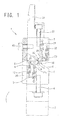
- FIG. 1 to 3 show a step-bending die device according to the present invention, which is attached to a press brake or the like (not shown).
- This step-bending die device 1 is composed of a die 2 and a punch 3 having a symmetrical structure in the up and down direction.
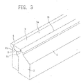
- the die 2 firstly, as shown in FIG. 3 , the die 2 has a rectangular parallelepiped shape extending in the lateral direction and has a horizontal surface 5 and an inclined surface 6 on the upper surface thereof, and the horizontal surface and the inclined surface are divided at the center in the short-side direction and extended in the longitudinal direction thereof.
- This die 2 is fixed to the die base 7 with a fixing bolt 4, but the die 2 can be moved in the horizontal direction (the left and the right direction) when the fixing bolt 4 is loosened.
- a semicircular groove 8 with a semicircular cross section is formed in the longitudinal direction on the horizontal surface 5, and a semicircular rotary blade 9 with a semicircular cross section is installed in the semicircular groove 8.
- the semicircular rotary blade 9 has a horizontally long shape like the semicircular groove 8 and is composed of a flat surface 9a and a circular arc surface 9b.
- the circular arc surface 9b faces the semicircular groove 8 and makes surface contact with it so that the semicircular rotary blade 9.is rotatable because of the same shape.
- the inclined surface 6 extends from the horizontal surface 5 at an appropriate angle ⁇ 1, for example, at about 30 degrees, and has two steps made by providing a step in the middle thereof.
- a vertical notch 15 that communicates with the inside of the semicircular groove 8 and is vertically cut is formed at a position changing from horizontal surface 5 to the incline surface 6.
- the vertical notch 15 is formed on the right side of the semicircular groove 8 on the drawing, whereby a top portion 16 extending in the longitudinal direction is formed at a position changing from the horizontal surface 5 to the incline surface 6.
- the top portion 16 is responsible for pressing the workpiece W during the step bending process.
- angle ⁇ 2 formed by the vertical portion 15a of the vertical notch 15 and the inclined surface 6 is at about 60 degrees.
- the punch 3 has the same structure as the die 2. Namely, The punch 3 has a rectangular parallelepiped shape which is long in the lateral direction and has a horizontal surface 25 and an inclined surface 26 on the lower surface. The punch 3 is attached via a fixing bolt 37 and a clamp 38 and assembled so that the horizontal surface25 faces the inclined surface 6 of the die 2 and the inclined surface 6 faces the horizontal surface 5 of the die 2.
- a semicircular groove 28 is formed on the horizontal surface 25, a semicircular rotary blade 29 with a semicircular cross section is installed in the semicircular groove 28.
- the semicircular rotary blade 29 has a horizontally long shape like the semicircular groove 28 and is composed of a flat surface 29a and an arcuate surface 29b. The arcuate surface 29b faces the semicircular groove 28 and comes in surface contact with the semicircular groove 28, so that the semicircular rotary blade 29 become rotatable.
- the semicircular rotary blade 29 is supported by a tension spring 31 for holding the semicircular rotary blade in order to keep it in the semicircular groove 28 (because it does not fall), and biased by a rotation return tension spring 32 giving rotation force in the counterclockwise direction.
- a tension spring 31 for holding semicircular rotary blade abuts the wall portion of the punch 3 and serves as a rotation stopper in the counterclockwise direction. This position makes a flat surface 29a to the semicircular rotary blade 29 horizontal and makes the horizontal surface 25 flush.
- the inclined surface 26 extends from the horizontal surface 25 at an appropriate angle ⁇ 3, for example, at about 30 degrees, and has two steps made by providing a step in the middle thereof.
- a vertical notch 35 that communicates with the inside of the semicircular groove 28 and is vertically cut is formed at a position changing from horizontal surface 25 to the incline surface 26.
- the vertical notch 35 is formed on the left side of the semicircular groove 28 on the drawing, whereby a top portion 36 extending in the longitudinal direction is formed at a position changing from the horizontal surface 25 to the incline surface 26.
- the top portion 36 is responsible for pressing the workpiece W during the step bending process.
- angle ⁇ 4 formed by the vertical portion 35a of the vertical notch 35 and the inclined surface 26 is at about 60 degrees.
- a vertical line along the vertical portion 35a of the vertical notch 35 is on the same line as the vertical line along the vertical portion 15a of the vertical notch 15 formed in the die 2, and when the workpiece is imposed between the adjuster plate 39 fixed to the punch 3 and the die 2, the vertical lines are adjusted to both vertical line's gap with a size equal to the thickness of the workpiece.
- FIG. 5 shows that: the die 2 and the punch 3 are apart and the workpiece W or the shim is interposed between the die 2 and the adjuster plate 39, and then the die 2 is fixed to the die base 7 with a fixing bolt 4. Then, the die 2 is moved in the left and the right direction thereof, and the thickness dimension e of the workpiece can be obtained between the top portion 16 of the die 2 and the top portion 36 of the punch 3 (between the vertical portion 15a and the vertical portion 35a). Namely, though the die 2 is moved in order to create the relative position of the die 2 and the punch 3, it is possible to move the punch 3 reversely to obtain the same result.
- FIG. 5 shows that the punch 3 is lowered after placing the workpiece W on the die 2.
- the top portion 36 of the punch 3 is in contact with a top surface of the workpiece W.
- the semicircular rotary blade 9 on the horizontal surface 5 of the die 2 also comes in contact with the lower left side of the workpiece W, and the top portion 16 of the die 2 also comes in contact with the flat surface of the workpiece W.
- the semicircular rotary blade 29 on the horizontal surface 25 of the punch 3 makes contact with the upper right side of the workpiece W for the first time.
- FIG. 6 shows that: when the punch 3 is lowered further from the state shown in FIG. 5 , the top portion 16 of the die 2 presses the workpiece W from below, and the top portion 36 of the punch 3 presses the workpiece W from above. Then, the top portion 16 enters the vertical notch 35 while bending the workpiece W, and at the same time, the top portion 36 enters the vertical notch 15 while bending the workpiece W.
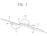
- the semicircular rotary blades 9 and 29 are rotated in the clockwise direction within their own semicircular grooves 8 and 28 by reaction force against the pressing forces having different directions from the top portions 16 and 36. Then, both semicircular rotary blades 9 and 29 constantly press the workpiece W from the backward thereof. Namely, as shown in FIG. 7 in detail, the workpiece W is divided to three parts that are a stepped portion W1 which is made at right angle at the midpoint of the gap e between both top portions 16 and 36 and two left and right pieces W2 and W3 which is made on the both sides of the stepped portion W1, and the three parts are bent separately.
- the step size D is obtained in proportion to the stroke amount of the punch 3 (amount of change in the relative position between the die 2 and the punch 3), and, for example, if the step size D of 2mm is obtained when the thickness of the workpiece W is 1 mm, in the case of Applicant's installation press brake, the numerical values are SB 306, 99.
- the step size D can be obtained from about 1.5 mm to about 3.5 mm.
Landscapes
- Engineering & Computer Science (AREA)
- Mechanical Engineering (AREA)
- Bending Of Plates, Rods, And Pipes (AREA)
Claims (5)
- Biegevorrichtung (1), umfassend eine Matrize (2) und einen Stempel (3), um Stufen auf einem Werkstück durch Verändern der Relativposition der Matrize (2) und des Stempels (3) auszuformen:wobei die Matrize (2) durch eine horizontale Fläche (5) und eine geneigte Fläche (6) ausgebildet ist, wobei eine halbrunde Nut (8) mit einem halbrunden Querschnitt entlang einer Längsrichtung auf der horizontalen Fläche (5) gebildet und rotierbar in der halbrunden Nut (8) ein halbrundes Rotationsmesser (9) installiert ist,wobei der Stempel (3) durch eine horizontale Fläche (25) und eine geneigte Fläche (26) ausgebildet ist, wobei eine halbrunde Nut (28) mit einem halbrunden Querschnitt entlang einer Längsrichtung auf der horizontalen Fläche (25) gebildet und rotierbar in der halbrunden Nut (28) ein halbrundes Rotationsmesser (29) installiert ist, undwobei der Stempel (3) als Abkantpresse mit einem Symmetriepunkt bezüglich der Matrize (2) montiert ist, so dass die horizontale Fläche (25) des Stempels (3) der geneigten Fläche (6) der Matrize (2) gegenübersteht und die geneigte Fläche (6) des Stempels (3) der horizontalen Fläche (5) der Matrize (2) gegenübersteht,dadurch gekennzeichnet,dass in Längsrichtung der Matrize (2) und des Stempels (3) vertikale Kerben (15, 35) an Wechselpositionen von den horizontalen Flächen (5, 25) zu den geneigten Flächen (6, 26) angeformt sind, die mit den halbrunden Nuten (8, 28) in Verbindung stehen, so dass in der Matrize (2) und in dem Stempel (3) in den Längsrichtungen jeweils obere Teile geformt sind, unddass Spannfedern (11, 31) vorgesehen sind, welche die halbrunden Rotationsmesser (9, 29) halten und über die die beiden halbrunden Rotationsmesser (9, 29) jeweils in den beiden halbrunden Nuten (8, 28) installiert sind.
- Biegevorrichtung nach Anspruch 1, dadurch gekennzeichnet, dass die Matrize (2) und der Stempel (3) einen Abstand zwischen vertikalen Linien entlang vertikaler Teile der vertikalen Kerben (15, 35) verändern, die sowohl in der Matrize (2) als auch in dem Stempel (3) angeformt sind, indem zwischen diesen eine Relativposition in einer Links-Rechts-Richtung verändert wird.
- Biegevorrichtung nach Anspruch 1 oder 2, dadurch gekennzeichnet, dass eine Ausrichtplatte (39) am Stempel (3) mittels einer Schraube fixiert ist, um eine Position in Rechtsrichtung zu regulieren, wobei im Biegeprozess das Werkstück oder ein Klemmstück zwischen der Ausrichtplatte (39) und der Matrize (2) angeordnet ist und die Position anschließend in Links- und Rechtsrichtung der Matrize (2) zu einer Matrizenbasis (7) fixiert ist.
- Biegevorrichtung nach einem der Ansprüche 1 bis 3, dadurch gekennzeichnet, dass jeweils Spannungsrückstellfedern zur Rückstellung beider Rotationsmesser in eine Richtung vorgesehen sind.
- Biegevorrichtung nach einem der Ansprüche 1 bis 4, dadurch gekennzeichnet, dass die Stufengröße durch das Maß der Änderung der Relativposition in Vertikalrichtung der Matrize (2) und des Stempels (3) festgelegt wird.
Applications Claiming Priority (1)
| Application Number | Priority Date | Filing Date | Title |
|---|---|---|---|
| PCT/JP2016/082541 WO2018083748A1 (ja) | 2016-11-02 | 2016-11-02 | 段曲げ加工金型 |
Publications (3)
| Publication Number | Publication Date |
|---|---|
| EP3342496A4 EP3342496A4 (de) | 2018-07-04 |
| EP3342496A1 EP3342496A1 (de) | 2018-07-04 |
| EP3342496B1 true EP3342496B1 (de) | 2019-03-13 |
Family
ID=62075873
Family Applications (1)
| Application Number | Title | Priority Date | Filing Date |
|---|---|---|---|
| EP16845357.9A Active EP3342496B1 (de) | 2016-11-02 | 2016-11-02 | Stufenbiegevorrichtung |
Country Status (4)
| Country | Link |
|---|---|
| US (1) | US10421109B2 (de) |
| EP (1) | EP3342496B1 (de) |
| JP (1) | JP6377264B1 (de) |
| WO (1) | WO2018083748A1 (de) |
Families Citing this family (4)
| Publication number | Priority date | Publication date | Assignee | Title |
|---|---|---|---|---|
| USD914775S1 (en) * | 2018-01-31 | 2021-03-30 | Nikkeikin Aluminium Core Technology Company, Ltd. | Bending die for metal plate |
| CN114669661B (zh) * | 2021-11-03 | 2023-08-15 | 内蒙古第一机械集团股份有限公司 | 一种特种钢零件的冲压模具 |
| IT202200010577A1 (it) * | 2022-05-23 | 2023-11-23 | Sares S P A | Apparecchiatura e procedimento per realizzare un profilo a z su una parte in lamiera |
| CN115283496B (zh) * | 2022-07-05 | 2025-08-15 | 青岛杰瑞工控技术有限公司 | 一种手持式防松垫板自动折弯及折弯缓解装置 |
Family Cites Families (17)
| Publication number | Priority date | Publication date | Assignee | Title |
|---|---|---|---|---|
| JPS5721418U (de) * | 1980-07-05 | 1982-02-03 | ||
| US4592518A (en) * | 1982-02-26 | 1986-06-03 | Tapco Products Company, Inc. | Coil holder |
| JPS63108918A (ja) * | 1986-10-24 | 1988-05-13 | Toru Mitsuyoshi | プレス用段曲げ金型 |
| JPH02108419A (ja) * | 1988-10-19 | 1990-04-20 | Fujitsu Ltd | 段曲げ型 |
| JPH0543935Y2 (de) * | 1990-12-07 | 1993-11-08 | ||
| DE4203680C1 (de) * | 1992-02-08 | 1993-05-06 | Iska Wolfgang Katz Verwaltungs-Gmbh, 7735 Dauchingen, De | |
| JPH05317972A (ja) * | 1992-05-19 | 1993-12-03 | Shinya Mitsuyoshi | 段曲げ金型装置 |
| US5365766A (en) * | 1993-05-18 | 1994-11-22 | Amada Engineering & Service Co., Inc. | Die assembly having means for automatically controlling in the angular orientation of the lower die plate members |
| US5746082A (en) * | 1997-02-05 | 1998-05-05 | Umix Co., Ltd. | Thin sheet forming die assembly including lower die cylindrical member having varied diameters |
| GB2368304A (en) * | 2000-06-23 | 2002-05-01 | Taigaa Koosan Yuugenkaisha | Metal sheet bending device with rotation inhibiting function |
| WO2002013987A1 (en) * | 2000-08-11 | 2002-02-21 | Amada Company, Limited | Bending method and device therefore |
| JP3832416B2 (ja) * | 2002-02-21 | 2006-10-11 | 村田機械株式会社 | 曲げ機能付き板材加工機 |
| US7454943B2 (en) * | 2003-07-15 | 2008-11-25 | Tooling Innovations, Inc. | Articulated bending brake for sheet metal forming |
| JP5314383B2 (ja) * | 2008-10-30 | 2013-10-16 | 株式会社北川製作所 | プレス曲げ機用金型 |
| JP4949441B2 (ja) * | 2009-08-06 | 2012-06-06 | 攻 牧野 | プレス曲げ加工用下型及びこれを用いた工具 |
| US8322181B2 (en) * | 2010-04-29 | 2012-12-04 | Ready Technology, Inc. | Rotary bending system |
| US9481026B2 (en) * | 2014-10-27 | 2016-11-01 | Tyco Electronics Corporation | Press device with adjustment mechanism |
-
2016
- 2016-11-02 EP EP16845357.9A patent/EP3342496B1/de active Active
- 2016-11-02 US US15/516,744 patent/US10421109B2/en active Active
- 2016-11-02 WO PCT/JP2016/082541 patent/WO2018083748A1/ja not_active Ceased
- 2016-11-02 JP JP2017516797A patent/JP6377264B1/ja active Active
Non-Patent Citations (1)
| Title |
|---|
| None * |
Also Published As
| Publication number | Publication date |
|---|---|
| EP3342496A4 (de) | 2018-07-04 |
| JPWO2018083748A1 (ja) | 2018-11-08 |
| JP6377264B1 (ja) | 2018-08-22 |
| US20180264532A1 (en) | 2018-09-20 |
| WO2018083748A1 (ja) | 2018-05-11 |
| US10421109B2 (en) | 2019-09-24 |
| EP3342496A1 (de) | 2018-07-04 |
Similar Documents
| Publication | Publication Date | Title |
|---|---|---|
| EP3342496B1 (de) | Stufenbiegevorrichtung | |
| EP2878395B1 (de) | Gesenkbefestigungsstruktur, Gesenkteilstruktur und Bilderzeugungsvorrichtung | |
| JP2009113078A (ja) | プレス成形用金型 | |
| US9656314B2 (en) | Press die | |
| JP6618669B2 (ja) | 曲げ加工器 | |
| CN114393108B (zh) | 一种连接件钣金工艺及其工艺系统 | |
| JP2009050873A (ja) | プレス成形型 | |
| US7343774B2 (en) | Comb system for tool spacers | |
| KR20130008260A (ko) | 각도 조절이 가능한 밀링머신용 바이스 | |
| CN104384264A (zh) | 折弯机 | |
| EP1063041A2 (de) | Werkzeugsystem für spannenden Metallbearbeitung von plattenförmigen Werkstücken | |
| EP3009216B1 (de) | Werkzeugmaschine mit Schneideinsatzpositionierungssystem | |
| US6874346B1 (en) | Multi-form die base with rotatable anvils having alternative forming surfaces | |
| EP1847371A2 (de) | Lagerstruktur und Formpressvorrichtung mit dieser Struktur | |
| JPH08224619A (ja) | ワーク曲げ加工方法およびその装置 | |
| US20130307205A1 (en) | Clamping/releasing flange | |
| JP2013226795A (ja) | 案内具 | |
| CN204122537U (zh) | 折弯机 | |
| CN213080214U (zh) | 一种用于薄板类零件铣削加工的夹具 | |
| JP2010142836A (ja) | 板曲げ装置 | |
| JP7005014B2 (ja) | 鋼材の製造装置 | |
| JP3860517B2 (ja) | パイプ材の切込溝加工方法およびその装置 | |
| KR101787951B1 (ko) | 판재의 프레싱 가공장치 | |
| KR20140006117U (ko) | 론지 복원 지그용 서포트 | |
| EP3569324B1 (de) | Anlage und verfahren zur ausbildung wenigstens eines eckbereichs in einer metallplatte |
Legal Events
| Date | Code | Title | Description |
|---|---|---|---|
| STAA | Information on the status of an ep patent application or granted ep patent |
Free format text: STATUS: UNKNOWN |
|
| STAA | Information on the status of an ep patent application or granted ep patent |
Free format text: STATUS: THE INTERNATIONAL PUBLICATION HAS BEEN MADE |
|
| PUAI | Public reference made under article 153(3) epc to a published international application that has entered the european phase |
Free format text: ORIGINAL CODE: 0009012 |
|
| STAA | Information on the status of an ep patent application or granted ep patent |
Free format text: STATUS: REQUEST FOR EXAMINATION WAS MADE |
|
| 17P | Request for examination filed |
Effective date: 20170323 |
|
| A4 | Supplementary search report drawn up and despatched |
Effective date: 20180426 |
|
| AK | Designated contracting states |
Kind code of ref document: A1 Designated state(s): AL AT BE BG CH CY CZ DE DK EE ES FI FR GB GR HR HU IE IS IT LI LT LU LV MC MK MT NL NO PL PT RO RS SE SI SK SM TR |
|
| AX | Request for extension of the european patent |
Extension state: BA ME |
|
| GRAP | Despatch of communication of intention to grant a patent |
Free format text: ORIGINAL CODE: EPIDOSNIGR1 |
|
| STAA | Information on the status of an ep patent application or granted ep patent |
Free format text: STATUS: GRANT OF PATENT IS INTENDED |
|
| RIC1 | Information provided on ipc code assigned before grant |
Ipc: B21D 5/01 20060101AFI20181130BHEP |
|
| INTG | Intention to grant announced |
Effective date: 20181217 |
|
| GRAS | Grant fee paid |
Free format text: ORIGINAL CODE: EPIDOSNIGR3 |
|
| GRAA | (expected) grant |
Free format text: ORIGINAL CODE: 0009210 |
|
| STAA | Information on the status of an ep patent application or granted ep patent |
Free format text: STATUS: THE PATENT HAS BEEN GRANTED |
|
| AK | Designated contracting states |
Kind code of ref document: B1 Designated state(s): AL AT BE BG CH CY CZ DE DK EE ES FI FR GB GR HR HU IE IS IT LI LT LU LV MC MK MT NL NO PL PT RO RS SE SI SK SM TR |
|
| DAV | Request for validation of the european patent (deleted) | ||
| DAX | Request for extension of the european patent (deleted) | ||
| REG | Reference to a national code |
Ref country code: GB Ref legal event code: FG4D |
|
| REG | Reference to a national code |
Ref country code: CH Ref legal event code: EP Ref country code: AT Ref legal event code: REF Ref document number: 1107002 Country of ref document: AT Kind code of ref document: T Effective date: 20190315 |
|
| REG | Reference to a national code |
Ref country code: IE Ref legal event code: FG4D |
|
| REG | Reference to a national code |
Ref country code: DE Ref legal event code: R096 Ref document number: 602016011171 Country of ref document: DE |
|
| REG | Reference to a national code |
Ref country code: NL Ref legal event code: MP Effective date: 20190313 |
|
| REG | Reference to a national code |
Ref country code: LT Ref legal event code: MG4D |
|
| PG25 | Lapsed in a contracting state [announced via postgrant information from national office to epo] |
Ref country code: SE Free format text: LAPSE BECAUSE OF FAILURE TO SUBMIT A TRANSLATION OF THE DESCRIPTION OR TO PAY THE FEE WITHIN THE PRESCRIBED TIME-LIMIT Effective date: 20190313 Ref country code: LT Free format text: LAPSE BECAUSE OF FAILURE TO SUBMIT A TRANSLATION OF THE DESCRIPTION OR TO PAY THE FEE WITHIN THE PRESCRIBED TIME-LIMIT Effective date: 20190313 Ref country code: NO Free format text: LAPSE BECAUSE OF FAILURE TO SUBMIT A TRANSLATION OF THE DESCRIPTION OR TO PAY THE FEE WITHIN THE PRESCRIBED TIME-LIMIT Effective date: 20190613 Ref country code: FI Free format text: LAPSE BECAUSE OF FAILURE TO SUBMIT A TRANSLATION OF THE DESCRIPTION OR TO PAY THE FEE WITHIN THE PRESCRIBED TIME-LIMIT Effective date: 20190313 |
|
| PG25 | Lapsed in a contracting state [announced via postgrant information from national office to epo] |
Ref country code: GR Free format text: LAPSE BECAUSE OF FAILURE TO SUBMIT A TRANSLATION OF THE DESCRIPTION OR TO PAY THE FEE WITHIN THE PRESCRIBED TIME-LIMIT Effective date: 20190614 Ref country code: BG Free format text: LAPSE BECAUSE OF FAILURE TO SUBMIT A TRANSLATION OF THE DESCRIPTION OR TO PAY THE FEE WITHIN THE PRESCRIBED TIME-LIMIT Effective date: 20190613 Ref country code: NL Free format text: LAPSE BECAUSE OF FAILURE TO SUBMIT A TRANSLATION OF THE DESCRIPTION OR TO PAY THE FEE WITHIN THE PRESCRIBED TIME-LIMIT Effective date: 20190313 Ref country code: LV Free format text: LAPSE BECAUSE OF FAILURE TO SUBMIT A TRANSLATION OF THE DESCRIPTION OR TO PAY THE FEE WITHIN THE PRESCRIBED TIME-LIMIT Effective date: 20190313 Ref country code: RS Free format text: LAPSE BECAUSE OF FAILURE TO SUBMIT A TRANSLATION OF THE DESCRIPTION OR TO PAY THE FEE WITHIN THE PRESCRIBED TIME-LIMIT Effective date: 20190313 Ref country code: HR Free format text: LAPSE BECAUSE OF FAILURE TO SUBMIT A TRANSLATION OF THE DESCRIPTION OR TO PAY THE FEE WITHIN THE PRESCRIBED TIME-LIMIT Effective date: 20190313 |
|
| REG | Reference to a national code |
Ref country code: AT Ref legal event code: MK05 Ref document number: 1107002 Country of ref document: AT Kind code of ref document: T Effective date: 20190313 |
|
| PG25 | Lapsed in a contracting state [announced via postgrant information from national office to epo] |
Ref country code: AL Free format text: LAPSE BECAUSE OF FAILURE TO SUBMIT A TRANSLATION OF THE DESCRIPTION OR TO PAY THE FEE WITHIN THE PRESCRIBED TIME-LIMIT Effective date: 20190313 Ref country code: RO Free format text: LAPSE BECAUSE OF FAILURE TO SUBMIT A TRANSLATION OF THE DESCRIPTION OR TO PAY THE FEE WITHIN THE PRESCRIBED TIME-LIMIT Effective date: 20190313 Ref country code: CZ Free format text: LAPSE BECAUSE OF FAILURE TO SUBMIT A TRANSLATION OF THE DESCRIPTION OR TO PAY THE FEE WITHIN THE PRESCRIBED TIME-LIMIT Effective date: 20190313 Ref country code: ES Free format text: LAPSE BECAUSE OF FAILURE TO SUBMIT A TRANSLATION OF THE DESCRIPTION OR TO PAY THE FEE WITHIN THE PRESCRIBED TIME-LIMIT Effective date: 20190313 Ref country code: SK Free format text: LAPSE BECAUSE OF FAILURE TO SUBMIT A TRANSLATION OF THE DESCRIPTION OR TO PAY THE FEE WITHIN THE PRESCRIBED TIME-LIMIT Effective date: 20190313 Ref country code: PT Free format text: LAPSE BECAUSE OF FAILURE TO SUBMIT A TRANSLATION OF THE DESCRIPTION OR TO PAY THE FEE WITHIN THE PRESCRIBED TIME-LIMIT Effective date: 20190713 Ref country code: EE Free format text: LAPSE BECAUSE OF FAILURE TO SUBMIT A TRANSLATION OF THE DESCRIPTION OR TO PAY THE FEE WITHIN THE PRESCRIBED TIME-LIMIT Effective date: 20190313 |
|
| PG25 | Lapsed in a contracting state [announced via postgrant information from national office to epo] |
Ref country code: SM Free format text: LAPSE BECAUSE OF FAILURE TO SUBMIT A TRANSLATION OF THE DESCRIPTION OR TO PAY THE FEE WITHIN THE PRESCRIBED TIME-LIMIT Effective date: 20190313 Ref country code: PL Free format text: LAPSE BECAUSE OF FAILURE TO SUBMIT A TRANSLATION OF THE DESCRIPTION OR TO PAY THE FEE WITHIN THE PRESCRIBED TIME-LIMIT Effective date: 20190313 |
|
| REG | Reference to a national code |
Ref country code: DE Ref legal event code: R097 Ref document number: 602016011171 Country of ref document: DE |
|
| PG25 | Lapsed in a contracting state [announced via postgrant information from national office to epo] |
Ref country code: IS Free format text: LAPSE BECAUSE OF FAILURE TO SUBMIT A TRANSLATION OF THE DESCRIPTION OR TO PAY THE FEE WITHIN THE PRESCRIBED TIME-LIMIT Effective date: 20190713 Ref country code: AT Free format text: LAPSE BECAUSE OF FAILURE TO SUBMIT A TRANSLATION OF THE DESCRIPTION OR TO PAY THE FEE WITHIN THE PRESCRIBED TIME-LIMIT Effective date: 20190313 |
|
| PLBE | No opposition filed within time limit |
Free format text: ORIGINAL CODE: 0009261 |
|
| STAA | Information on the status of an ep patent application or granted ep patent |
Free format text: STATUS: NO OPPOSITION FILED WITHIN TIME LIMIT |
|
| PG25 | Lapsed in a contracting state [announced via postgrant information from national office to epo] |
Ref country code: DK Free format text: LAPSE BECAUSE OF FAILURE TO SUBMIT A TRANSLATION OF THE DESCRIPTION OR TO PAY THE FEE WITHIN THE PRESCRIBED TIME-LIMIT Effective date: 20190313 |
|
| 26N | No opposition filed |
Effective date: 20191216 |
|
| PG25 | Lapsed in a contracting state [announced via postgrant information from national office to epo] |
Ref country code: TR Free format text: LAPSE BECAUSE OF FAILURE TO SUBMIT A TRANSLATION OF THE DESCRIPTION OR TO PAY THE FEE WITHIN THE PRESCRIBED TIME-LIMIT Effective date: 20190313 |
|
| REG | Reference to a national code |
Ref country code: CH Ref legal event code: PL |
|
| PG25 | Lapsed in a contracting state [announced via postgrant information from national office to epo] |
Ref country code: LI Free format text: LAPSE BECAUSE OF NON-PAYMENT OF DUE FEES Effective date: 20191130 Ref country code: CH Free format text: LAPSE BECAUSE OF NON-PAYMENT OF DUE FEES Effective date: 20191130 Ref country code: MC Free format text: LAPSE BECAUSE OF FAILURE TO SUBMIT A TRANSLATION OF THE DESCRIPTION OR TO PAY THE FEE WITHIN THE PRESCRIBED TIME-LIMIT Effective date: 20190313 Ref country code: LU Free format text: LAPSE BECAUSE OF NON-PAYMENT OF DUE FEES Effective date: 20191102 |
|
| REG | Reference to a national code |
Ref country code: BE Ref legal event code: MM Effective date: 20191130 |
|
| PG25 | Lapsed in a contracting state [announced via postgrant information from national office to epo] |
Ref country code: IE Free format text: LAPSE BECAUSE OF NON-PAYMENT OF DUE FEES Effective date: 20191102 |
|
| PG25 | Lapsed in a contracting state [announced via postgrant information from national office to epo] |
Ref country code: BE Free format text: LAPSE BECAUSE OF NON-PAYMENT OF DUE FEES Effective date: 20191130 |
|
| PG25 | Lapsed in a contracting state [announced via postgrant information from national office to epo] |
Ref country code: CY Free format text: LAPSE BECAUSE OF FAILURE TO SUBMIT A TRANSLATION OF THE DESCRIPTION OR TO PAY THE FEE WITHIN THE PRESCRIBED TIME-LIMIT Effective date: 20190313 |
|
| GBPC | Gb: european patent ceased through non-payment of renewal fee |
Effective date: 20201102 |
|
| PG25 | Lapsed in a contracting state [announced via postgrant information from national office to epo] |
Ref country code: HU Free format text: LAPSE BECAUSE OF FAILURE TO SUBMIT A TRANSLATION OF THE DESCRIPTION OR TO PAY THE FEE WITHIN THE PRESCRIBED TIME-LIMIT; INVALID AB INITIO Effective date: 20161102 Ref country code: MT Free format text: LAPSE BECAUSE OF FAILURE TO SUBMIT A TRANSLATION OF THE DESCRIPTION OR TO PAY THE FEE WITHIN THE PRESCRIBED TIME-LIMIT Effective date: 20190313 |
|
| PG25 | Lapsed in a contracting state [announced via postgrant information from national office to epo] |
Ref country code: SI Free format text: LAPSE BECAUSE OF FAILURE TO SUBMIT A TRANSLATION OF THE DESCRIPTION OR TO PAY THE FEE WITHIN THE PRESCRIBED TIME-LIMIT Effective date: 20190313 |
|
| PG25 | Lapsed in a contracting state [announced via postgrant information from national office to epo] |
Ref country code: GB Free format text: LAPSE BECAUSE OF NON-PAYMENT OF DUE FEES Effective date: 20201102 |
|
| PG25 | Lapsed in a contracting state [announced via postgrant information from national office to epo] |
Ref country code: MK Free format text: LAPSE BECAUSE OF FAILURE TO SUBMIT A TRANSLATION OF THE DESCRIPTION OR TO PAY THE FEE WITHIN THE PRESCRIBED TIME-LIMIT Effective date: 20190313 |
|
| PGFP | Annual fee paid to national office [announced via postgrant information from national office to epo] |
Ref country code: DE Payment date: 20251128 Year of fee payment: 10 |
|
| PGFP | Annual fee paid to national office [announced via postgrant information from national office to epo] |
Ref country code: IT Payment date: 20251125 Year of fee payment: 10 |
|
| PGFP | Annual fee paid to national office [announced via postgrant information from national office to epo] |
Ref country code: FR Payment date: 20251126 Year of fee payment: 10 |