EP3342548A1 - Système de surveillance de robot - Google Patents
Système de surveillance de robot Download PDFInfo
- Publication number
- EP3342548A1 EP3342548A1 EP17210631.2A EP17210631A EP3342548A1 EP 3342548 A1 EP3342548 A1 EP 3342548A1 EP 17210631 A EP17210631 A EP 17210631A EP 3342548 A1 EP3342548 A1 EP 3342548A1
- Authority
- EP
- European Patent Office
- Prior art keywords
- robot
- image
- surveillance system
- standstill
- image capture
- Prior art date
- Legal status (The legal status is an assumption and is not a legal conclusion. Google has not performed a legal analysis and makes no representation as to the accuracy of the status listed.)
- Granted
Links
Images

Classifications
-
- A—HUMAN NECESSITIES
- A47—FURNITURE; DOMESTIC ARTICLES OR APPLIANCES; COFFEE MILLS; SPICE MILLS; SUCTION CLEANERS IN GENERAL
- A47L—DOMESTIC WASHING OR CLEANING; SUCTION CLEANERS IN GENERAL
- A47L11/00—Machines for cleaning floors, carpets, furniture, walls, or wall coverings
- A47L11/24—Floor-sweeping machines, motor-driven
-
- B—PERFORMING OPERATIONS; TRANSPORTING
- B25—HAND TOOLS; PORTABLE POWER-DRIVEN TOOLS; MANIPULATORS
- B25J—MANIPULATORS; CHAMBERS PROVIDED WITH MANIPULATION DEVICES
- B25J9/00—Program-controlled manipulators
- B25J9/16—Program controls
- B25J9/1674—Program controls characterised by safety, monitoring, diagnostic
- B25J9/1676—Avoiding collision or forbidden zones
-
- A—HUMAN NECESSITIES
- A47—FURNITURE; DOMESTIC ARTICLES OR APPLIANCES; COFFEE MILLS; SPICE MILLS; SUCTION CLEANERS IN GENERAL
- A47L—DOMESTIC WASHING OR CLEANING; SUCTION CLEANERS IN GENERAL
- A47L11/00—Machines for cleaning floors, carpets, furniture, walls, or wall coverings
- A47L11/40—Parts or details of machines not provided for in groups A47L11/02 - A47L11/38, or not restricted to one of these groups, e.g. handles, arrangements of switches, skirts, buffers, levers
- A47L11/4011—Regulation of the cleaning machine by electric means; Control systems and remote control systems therefor
-
- A—HUMAN NECESSITIES
- A47—FURNITURE; DOMESTIC ARTICLES OR APPLIANCES; COFFEE MILLS; SPICE MILLS; SUCTION CLEANERS IN GENERAL
- A47L—DOMESTIC WASHING OR CLEANING; SUCTION CLEANERS IN GENERAL
- A47L11/00—Machines for cleaning floors, carpets, furniture, walls, or wall coverings
- A47L11/40—Parts or details of machines not provided for in groups A47L11/02 - A47L11/38, or not restricted to one of these groups, e.g. handles, arrangements of switches, skirts, buffers, levers
- A47L11/4061—Steering means; Means for avoiding obstacles; Details related to the place where the driver is accommodated
-
- G—PHYSICS
- G05—CONTROLLING; REGULATING
- G05D—SYSTEMS FOR CONTROLLING OR REGULATING NON-ELECTRIC VARIABLES
- G05D1/00—Control of position, course, altitude or attitude of land, water, air or space vehicles, e.g. using automatic pilots
- G05D1/02—Control of position or course in two dimensions
- G05D1/021—Control of position or course in two dimensions specially adapted to land vehicles
- G05D1/0231—Control of position or course in two dimensions specially adapted to land vehicles using optical position detecting means
- G05D1/0246—Control of position or course in two dimensions specially adapted to land vehicles using optical position detecting means using a video camera in combination with image processing means
- G05D1/0248—Control of position or course in two dimensions specially adapted to land vehicles using optical position detecting means using a video camera in combination with image processing means in combination with a laser
-
- G—PHYSICS
- G06—COMPUTING OR CALCULATING; COUNTING
- G06T—IMAGE DATA PROCESSING OR GENERATION, IN GENERAL
- G06T7/00—Image analysis
- G06T7/20—Analysis of motion
-
- H—ELECTRICITY
- H04—ELECTRIC COMMUNICATION TECHNIQUE
- H04N—PICTORIAL COMMUNICATION, e.g. TELEVISION
- H04N23/00—Cameras or camera modules comprising electronic image sensors; Control thereof
- H04N23/50—Constructional details
- H04N23/55—Optical parts specially adapted for electronic image sensors; Mounting thereof
-
- H—ELECTRICITY
- H04—ELECTRIC COMMUNICATION TECHNIQUE
- H04N—PICTORIAL COMMUNICATION, e.g. TELEVISION
- H04N23/00—Cameras or camera modules comprising electronic image sensors; Control thereof
- H04N23/56—Cameras or camera modules comprising electronic image sensors; Control thereof provided with illuminating means
-
- H—ELECTRICITY
- H04—ELECTRIC COMMUNICATION TECHNIQUE
- H04N—PICTORIAL COMMUNICATION, e.g. TELEVISION
- H04N7/00—Television systems
- H04N7/18—Closed-circuit television [CCTV] systems, i.e. systems in which the video signal is not broadcast
- H04N7/183—Closed-circuit television [CCTV] systems, i.e. systems in which the video signal is not broadcast for receiving images from a single remote source
- H04N7/185—Closed-circuit television [CCTV] systems, i.e. systems in which the video signal is not broadcast for receiving images from a single remote source from a mobile camera, e.g. for remote control
-
- A—HUMAN NECESSITIES
- A47—FURNITURE; DOMESTIC ARTICLES OR APPLIANCES; COFFEE MILLS; SPICE MILLS; SUCTION CLEANERS IN GENERAL
- A47L—DOMESTIC WASHING OR CLEANING; SUCTION CLEANERS IN GENERAL
- A47L2201/00—Robotic cleaning machines, i.e. with automatic control of the travelling movement or the cleaning operation
- A47L2201/04—Automatic control of the travelling movement; Automatic obstacle detection
-
- G—PHYSICS
- G05—CONTROLLING; REGULATING
- G05B—CONTROL OR REGULATING SYSTEMS IN GENERAL; FUNCTIONAL ELEMENTS OF SUCH SYSTEMS; MONITORING OR TESTING ARRANGEMENTS FOR SUCH SYSTEMS OR ELEMENTS
- G05B2219/00—Program-control systems
- G05B2219/30—Nc systems
- G05B2219/39—Robotics, robotics to robotics hand
- G05B2219/39082—Collision, real time collision avoidance
-
- G—PHYSICS
- G05—CONTROLLING; REGULATING
- G05B—CONTROL OR REGULATING SYSTEMS IN GENERAL; FUNCTIONAL ELEMENTS OF SUCH SYSTEMS; MONITORING OR TESTING ARRANGEMENTS FOR SUCH SYSTEMS OR ELEMENTS
- G05B2219/00—Program-control systems
- G05B2219/30—Nc systems
- G05B2219/40—Robotics, robotics mapping to robotics vision
- G05B2219/40548—Compare measured distances to obstacle with model of environment
-
- G—PHYSICS
- G05—CONTROLLING; REGULATING
- G05B—CONTROL OR REGULATING SYSTEMS IN GENERAL; FUNCTIONAL ELEMENTS OF SUCH SYSTEMS; MONITORING OR TESTING ARRANGEMENTS FOR SUCH SYSTEMS OR ELEMENTS
- G05B2219/00—Program-control systems
- G05B2219/30—Nc systems
- G05B2219/45—Nc applications
- G05B2219/45098—Vacuum cleaning robot
-
- H—ELECTRICITY
- H04—ELECTRIC COMMUNICATION TECHNIQUE
- H04W—WIRELESS COMMUNICATION NETWORKS
- H04W4/00—Services specially adapted for wireless communication networks; Facilities therefor
- H04W4/80—Services using short range communication, e.g. near-field communication [NFC], radio-frequency identification [RFID] or low energy communication
Definitions
- the present invention generally relates to a robot surveillance system, and more specifically to a robot surveillance system for controlling a proceeding direction of a robot by detecting change of the specific optic pattern on an object to implement a function of spatial security and surveillance.
- the clean robot in the prior arts is an automatic clean device, which freely moves without any control of the user.
- the clean robot can move around the indoor space like house or office to remove dirty stuff (such as trash or dust) on the ground to the built-in container or box so as to implement effect of clean indoor environment.
- dirty stuff such as trash or dust
- the clean robot gradually becomes a must for the modern married couple working and busy all day.
- the traditional clean robot has some limitations in use. For example, all pieces of the indoor furniture are placed at various locations dependent on the user, and the arraignment possibly changes over time. If the indoor space has a structure of ladder or regions with different heights, and the clean path of the clean robot is not updated, the clean robot still moves along the preset clean route and fails to implement effective cleaning for all preset regions.
- the clean robot might even fall down or collide with surrounding stuffs.
- a block device or so called a virtual wall
- the virtual wall transmits a block signal
- the clean robot receives the block signal to move backward or obliquely so as to avoid collision or falling down.
- the robot is provided with a plurality of cameras or ultrasonic wave sensors to determine the objects in front.
- the ultrasonic wave sensor fails to effectively determine if any slight bump object like an electric wire or network cable is placed on the floor. As a result, the robot easily gets entangled and tightly stuck by the wire. Particularly, the ultrasonic wave sensor is expensive, and the process of installation is quite complicated.
- the primary objective of the present invention is to provide a robot surveillance system, and more specifically to a robot surveillance system for controlling a traveling direction of a robot by detecting change of the specific optic pattern on an object to implement a function of spatial security and surveillance.
- the robot surveillance system of the present invention utilizes a specific hardware to incorporate the image capture unit with the optic pattern emitted by the light-emitting unit for providing the robot with the visual module.
- the optic pattern according to the image captured by the image capture unit changes because the robot is moving and about to collide with the standstill object like a hump or recess
- the image processing unit recognizes and confirms that the standstill object is present, and controls the robot to turn so as to instantly avoid collision or falling down.
- the present invention can detect the moving object in the space by means of motion detection to effectively implement spatial security and surveillance, thereby greatly decreasing cost of hardware and manpower, improving precision of detection and surveillance, and providing instant warning.
- the present invention provides a robot surveillance system, comprising a system server, a communication network, and a plurality of client devices.
- the at least one light-emitting unit is provided on an outer part of a robot, and each light-emitting unit emits a light beam, which comprises an optical pattern incident on and shown by at least one standstill object or at least one moving object in space.
- the optical pattern changes dependent on the standstill object or the moving object.
- the image capture unit is provided on the outer part of the robot, and comprises an optic lens and a photo-sensing device connected together. The optic lens captures an image of the standstill or moving object to cause the photo-sensing device to form a captured image of the optical pattern from the standstill or moving object.
- the image processing unit is electrically connected to the image capture unit for receiving the captured image of the image capture unit.
- the image processing unit comprises a detection module, a recognition module, and a motion detection module.
- the detection module detects the optic pattern from the image capture unit. When the optic pattern changes due to the standstill object, a distance away from the standstill object is calculated and a first signal is generated and transferred. When a comparison result of the image showing not consistent is confirmed by the recognition module examining and comparing information of the image from the image capture unit, a second signal is generated and transferred. When the motion detection module detects the moving object in the image, a third signal is generated and transferred.
- the turning control unit is electrically connected to the detection module for receiving the first signal of the detection module to control the robot to turn to avoid the standstill object.
- the wireless transceiver unit is electrically connected to the recognition module and the motion detection module for receiving the image, the second signal, and the third signal from the recognition module and the motion detection module to wireless transfer to a user at a remote surveillance device
- the at least one light-emitting unit is one of a laser, a light-emitting diode, and a luminary for emitting the light beam.
- the optic pattern is one of a grid, a straight line, and dots regularly arranged.
- the standstill object is at least one of an object placed on the ground, a recess of the ground, and a hump of the ground.
- the optic lens is one of a fish-eye lens, a wide-angle lens, and a standard lens.
- the photo-sensing device is one of a charge coupled device (CCD) and a complementary metal oxide semiconductor (CMOS).
- CCD charge coupled device
- CMOS complementary metal oxide semiconductor
- the recognition mode reads the information of the image through means of face recognition, bar code recognition, or pattern recognition, and compares with a plurality of built-in comparison data in the recognition module.
- the recognition module further comprises a store module for storing the plurality of built-in comparison data.
- the motion detection module employs means of object motion detection, light flow detection, or object outline detection to detect the moving object.
- the communication protocol is at least one of Bluetooth communication protocol, infrared communication protocol, near-field communication (NFC), wireless local area networks (WLAN), WiGig, Zigbee, Wireless USB, ultra-wide band (UWB), and WiFi for providing the wireless transceiver unit with a function of communication with the remote surveillance device.
- Bluetooth communication protocol infrared communication protocol
- NFC near-field communication
- WLAN wireless local area networks
- WiGig wireless local area networks
- Zigbee Wireless USB
- UWB ultra-wide band
- the remote surveillance device is one of a mobile communication device, a remote device, and a computer device.
- the light-emitting unit is a flickering light source, having a flickering frequency the same as an image capture frequency of the image capture unit.
- the detection module of the image processing unit examines and compares differences between two successive images captured by the image capture unit to identify change of the optic pattern.
- the robot surveillance system of the present invention utilizes the specific hardware to incorporate the image capture unit with the optic pattern emitted by the light-emitting unit for providing the clean robot with the visual module. That is, the optic pattern according to the image captured by the image capture unit changes because the clean robot is moving and about to collide with the standstill object like a hump or recess, the image processing unit recognizes and confirms that the standstill object is present, and controls the robot to turn so as to instantly avoid collision or falling down.
- the present invention overcomes the issue that the traditional robot needs expensive laser radar or ultrasonic wave to avoid collision, and implements the advantage of cost down for hardware.
- the robot surveillance system of the present invention provides the image capture unit and the at least light-emitting unit emitting the optic pattern in pair as the surveillance module of various robots, and monitors at least one moving object by means of motion object detection, light flow detection, and object outline detection so as to effectively implementing spatial security and image transfer.
- the present invention employs means of image capture, detection, and identification like face recognition, bar code recognition, or pattern recognition to deeply patrol around the large scale factory or the residence building, and identify the strangers invading the factor or the building.
- the present invention utilizes the change of the optic pattern emitted by the light-emitting unit to detect any object on the ground like electric wire or cable, thereby effectively overcoming the problem that the traditional clean robot fails to exactly detect the height of the hump on the ground and gets stuck, leading to waste lots of power. It is obvious the present invent can avoid any obstacle on the ground and save power consumption.
- the robot surveillance system of the present invention is intended to prevent a robot 2 from falling down or collision by detecting change of an optic pattern 111, and implement detection of at least one moving object invading the concerned region in space to achieve the aim of security and surveillance.
- the robot 2 is but not limited to a cleaning robot 21 for cleaning the indoor environment of a house or office, and security/surveillance.
- the robot 2 is but not limited to a patrol robot for patrolling around a building or a large scale factory, and further monitoring any undesired person invading the specific region.
- the robot surveillance system of the present invention generally comprises at least one light-emitting unit 1, an image capture unit 3, an image processing unit 4, a turning control unit 5, and a wireless transceiver unit 6.
- the at least one light-emitting unit 1 is provided on the outer part of the robot 2, and each light-emitting unit 1 emits a light beam 11 comprising an optical pattern 111, which is incident on and shown by at least one standstill object or at least one moving object in space.
- the optical pattern will change dependent on the standstill object or the moving object.
- the at least one light-emitting unit 1 is one of a laser, a light-emitting diode, and a luminary for emitting the light beam.
- the optic pattern 11 is one of a grid, a straight line, and dots regularly arranged
- the standstill object is at least one of an object placed on the ground, a recess of the ground, and a hump of the ground.
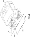
- the cleaning robot 21 is implemented by a robot 2, which has an outer provided with two adjacent lasers as the light-emitting units 1.
- the two light beams 11 emitted by two lasers comprises the optic patterns like straight lines.
- one of the two light beams 11 horizontally travels forward in parallel such that the object standing on the ground or a hump of the ground as the standstill object is detected by use of the straight line pattern.
- the other light beam 11 of the light-emitting unit 1 oblique travels toward the ground such that the standstill object standing in a recess of the ground is detected by use of the straight line pattern.
- the image capture unit 3 is provided on the outer part of the robot 2, and comprises an optic lens 31 and a photo-sensing device 32 connected to the optic lens 31.
- the optic lens 31 is configured to capture an image of the standstill or moving object to cause the photo-sensing device 32 to form a captured image based on the optical pattern from the standstill or moving object.
- the optic lens 31 is one of a fish-eye lens, a wide-angle lens, and a standard lens
- the photo-sensing device 32 is one of a charge coupled device (CCD) and a complementary metal oxide semiconductor (CMOS).
- CCD charge coupled device
- CMOS complementary metal oxide semiconductor
- the optic lens 31 and the photo-sensing device 32 are implemented by the fish-eye lens and the CCD, respectively.
- the image capture unit 3 is provided on the outer part of the robot 2 with respect to the light-emitting unit 1, and the image of the optic pattern 111 is formed on the photo-sensing device 32.
- the image processing unit 4 is electrically connected to the image capture unit 3 for receiving the image captured by the image capture unit 3, and comprises a detection module 41, a recognition module 42, and a motion detection module 43
- the detection module 41 detects the optic pattern 111 in the image. When the optic pattern 111 changes due to the standstill object, a distance away from the standstill object is calculated and a first signal S1 is generated and transferred by the detection module 41.
- the recognition module 42 examines and compares information of the image from the image capture unit 3. When a comparison result of the image shows not consistent, the recognition module 42 generates and transfers a second signal S2.
- the motion detection module 43 detects the moving object in the image to generate and transfer a third signal S3.
- the recognition mode 42 reads the information of the image through means of face recognition, bar code recognition, or pattern recognition, and compares with a plurality of built-in comparison data in the recognition module 42.
- the recognition mode 42 further comprises a store module (not shown) for storing the plurality of built-in comparison data.
- the motion detection module 43 employs means of object motion detection, light flow detection, or object outline detection to detect the moving object.
- the detection module 41 of the image processing unit 4 is configured for receiving the image captured by the image capture unit 3, and determines if the optic pattern 111 is incident on the standstill object and thus changes. If the optic pattern 111 changes, the detection module 41 issues the first signal S1 and calculates the distance away from the standstill object.
- the detection module 42 is suitably applicable to the patrol robot of the second embodiment.
- means of bar code identification is employed to compare the built-in comparison data with the bar code on the person like employee ID.
- the recognition module 42 transfers the person's image and the second signal S2
- the motion detection module 43 utilizes means of light flow detection to implement the goal of security and surveillance by detecting the moving object in the space invading the secured region, and then transfers the image and the third signal S3.
- the turning control unit 5 is electrically connected to the detection module 41 for receiving the first signal S1 of the detection module 41 to control the robot 2 to correctly turn to avoid the detected standstill object.
- the detection module 41 when the detection module 41 receives the captured image from the image capture unit 3 and confirms that the optic pattern 111 incident on the standstill object changes, the detection module 41 issues the first signal S1 to the turning control unit 5, thereby controlling the robot 2 to appropriately turn and preventing risk of colliding with the standstill object.
- the wireless transceiver unit 6 is electrically connected to the recognition module 42 and the motion detection module 43. Specifically, the wireless transceiver unit 6 receives the image, the second signal S2, and the third signal S3 from the recognition module 42 and the motion detection module 43 to wireless transfer to a user at a remote surveillance device 7 through a wireless communication protocol.
- the communication protocol is at least one of Bluetooth communication protocol, infrared communication protocol, near-field communication (NFC), wireless local area networks (WLAN), WiGig, Zigbee, Wireless USB, ultra-wide band (UWB), and WiFi for providing the wireless transceiver unit 6 with a function of communication with the remote surveillance device 7.
- the remote surveillance device 7 is one of a mobile communication device, a remote device, and a computer device.
- the recognition module 42 confirms the comparison result is not consistent
- the image of the undesired person and the second signal S2 are transferred, and the wireless transceiver unit 6 employs the wireless communication protocol to further transfer the image and the second signal S2 to the mobile communication device by the user as the remote surveillance device 7 so as to warn or inform related persons of the situation that the residence building or the factory is invaded by some undesired person.
- the motion detection module 43 uses means of light flow detection to detect the moving object in the space
- the image and the third signal S3 are transferred to the wireless transceiver 6.
- the wireless transceiver 6 further transfers the image of the moving object to the remote surveillance device 7 of the user, thereby informing the related persons of the invasion event caused by the moving object, and at the same time, storing the image of the moving object.
- the light-emitting unit 1 is a flickering light source having a flickering frequency, which is the same as an image capture frequency of the image capture unit 3.
- the detection module 41 of the image processing unit 4 examines and compares the differences between two successive images captured by the image capture unit 3 to identify change of the optic pattern 111.
- the image capture unit 3 fetches one image of the standstill object and the optic pattern 111 on the standstill object, and when the light emitted light turns dark at the next moment, the current image of the standstill object and the optic pattern 111 is fetched.
- the detection module 41 performs subtraction of the above two successive images to extract only the part of the optic pattern 111 in the image for more precisely detecting and identifying the change of the optic pattern 111 and more strictly controlling the robot 2 to turn.
- the clean robot 21 provided with the robot surveillance system of the present invention is helpful because the clean robot 21 is prevented from colliding with some standstill object or falling down. Further, the clean robot 21 can surely monitor the moving object in the space by means of motion detection to effectively performing security and surveillance of the desired region, thereby providing the advantage of greatly decreasing cost of hardware and manpower, improving precision of detection and surveillance, and implementing instant warning.
- the at least one light-emitting unit 1 is prepared, and provided on the outer part of the robot 2.
- Each light-emitting unit 1 implemented by the laser emits a laser beam 11 comprising the specific optical pattern 111, which is incident on and shown by at least one standstill object or at least one moving object in space, As a result, the optic pattern 111 changes due to the standstill object or the moving object.
- the image capture unit 3 is prepared and provided on the outer part of the robot 2.
- the image capture unit 3 comprises the optic lens 31 and the photo-sensing device 32 connected together.
- the optic lens 31 is intended to capture the image of the standstill or moving object to cause the photo-sensing device 32 to form the captured image of the optical pattern 111 on the standstill or moving object.
- the image processing unit 4 electrically connected to the image capture unit 3 is prepared.
- the detection module 41 of the image processing unit 4 detects and identifies the optic pattern 111 transferred from the image capture unit 3, When the optic pattern 111 changes due to the standstill object, the distance away from the standstill object is calculated and the first signal S1 is thus generated and transferred to the turning control unit 5 so as to correctly control the robot 2 to turn and avoid the standstill object. Finally, the motion detection module 43 built-in by the image processing unit 4 is prepared. When the moving object in the space is detected by the motion detection module 43 through means of light flow detection, the image and the third signal S3 are transferred to the wireless transceiver unit 6.
- the wireless transceiver unit 6 transfers the received image to the remote surveillance device 7 employed by the user, like the mobile communication device, so as to inform the related persons of the information that invasion is resulted in by the moving object and instantly store the image.
- a specific hardware is designed by the system of the present invention to incorporate the image capture unit 3 with the optic pattern 111 emitted by the light-emitting unit 1, and intended to provide the clean robot 21 with the visual module.
- the image processing unit 4 recognizes and confirms that the standstill object is present, and controls the clean robot 21 to turn so as to instantly avoid collision or falling down. Therefore, the advantage of greatly decreasing cost of hardware is indeed implemented.
Landscapes
- Engineering & Computer Science (AREA)
- Multimedia (AREA)
- Signal Processing (AREA)
- Physics & Mathematics (AREA)
- General Physics & Mathematics (AREA)
- Computer Vision & Pattern Recognition (AREA)
- Robotics (AREA)
- Mechanical Engineering (AREA)
- Automation & Control Theory (AREA)
- Remote Sensing (AREA)
- Radar, Positioning & Navigation (AREA)
- Aviation & Aerospace Engineering (AREA)
- Optics & Photonics (AREA)
- Electromagnetism (AREA)
- Theoretical Computer Science (AREA)
- Control Of Position, Course, Altitude, Or Attitude Of Moving Bodies (AREA)
- Manipulator (AREA)
- Alarm Systems (AREA)
Applications Claiming Priority (1)
| Application Number | Priority Date | Filing Date | Title |
|---|---|---|---|
| TW105143466A TWI626427B (zh) | 2016-12-28 | 2016-12-28 | 適用於機器人之監測系統 |
Publications (2)
| Publication Number | Publication Date |
|---|---|
| EP3342548A1 true EP3342548A1 (fr) | 2018-07-04 |
| EP3342548B1 EP3342548B1 (fr) | 2021-10-27 |
Family
ID=60990590
Family Applications (1)
| Application Number | Title | Priority Date | Filing Date |
|---|---|---|---|
| EP17210631.2A Active EP3342548B1 (fr) | 2016-12-28 | 2017-12-27 | Système de surveillance de robot |
Country Status (5)
| Country | Link |
|---|---|
| US (1) | US20180181141A1 (fr) |
| EP (1) | EP3342548B1 (fr) |
| JP (1) | JP2018109978A (fr) |
| CN (1) | CN108245079B (fr) |
| TW (1) | TWI626427B (fr) |
Families Citing this family (8)
| Publication number | Priority date | Publication date | Assignee | Title |
|---|---|---|---|---|
| KR102017148B1 (ko) * | 2017-03-03 | 2019-09-02 | 엘지전자 주식회사 | 장애물을 학습하는 인공지능 이동 로봇 및 그 제어방법 |
| US11141863B2 (en) * | 2018-10-11 | 2021-10-12 | Pixart Imaging Inc. | Cleaning robot capable of detecting 2D depth information and operating method thereof |
| EP3900602A4 (fr) * | 2018-12-21 | 2022-09-14 | Positec Power Tools (Suzhou) Co., Ltd | Robot de nettoyage et procédé de commande |
| CN109765901A (zh) * | 2019-02-18 | 2019-05-17 | 华南理工大学 | 基于线激光与双目视觉的动态代价地图导航方法 |
| CN109990832A (zh) * | 2019-02-28 | 2019-07-09 | 芜湖赛宝机器人产业技术研究院有限公司 | 一种基于ZigBee技术便携式工业机器人监测装置 |
| CN110172939A (zh) * | 2019-05-22 | 2019-08-27 | 重庆北崎包装制品有限公司 | 一种智能扫地机器人 |
| CN110928305B (zh) * | 2019-12-03 | 2023-08-18 | 中国铁道科学研究院集团有限公司电子计算技术研究所 | 用于铁路客运车站巡更机器人的巡更方法及系统 |
| KR102320678B1 (ko) * | 2020-02-28 | 2021-11-02 | 엘지전자 주식회사 | 이동 로봇 및 그 제어방법 |
Citations (3)
| Publication number | Priority date | Publication date | Assignee | Title |
|---|---|---|---|---|
| US20150120056A1 (en) * | 2013-10-31 | 2015-04-30 | Lg Electronics Inc. | Mobile robot |
| US20150185322A1 (en) * | 2012-08-27 | 2015-07-02 | Aktiebolaget Electrolux | Robot positioning system |
| US20150290808A1 (en) * | 2014-04-10 | 2015-10-15 | Smartvue Corporation | Systems and methods for automated cloud-based analytics for security and/or surveillance |
Family Cites Families (11)
| Publication number | Priority date | Publication date | Assignee | Title |
|---|---|---|---|---|
| JPH01163806A (ja) * | 1987-12-21 | 1989-06-28 | Shinichi Yuda | 移動ロボットにおける路面環境検知装置 |
| JPH05341842A (ja) * | 1992-05-07 | 1993-12-24 | Nec Corp | 走行車の障害検知装置 |
| JPH0643935A (ja) * | 1992-07-24 | 1994-02-18 | Mutoh Ind Ltd | 走行ロボットの障害物検出装置 |
| JP2003296855A (ja) * | 2002-03-29 | 2003-10-17 | Toshiba Corp | 監視装置 |
| JP2006006639A (ja) * | 2004-06-25 | 2006-01-12 | Funai Electric Co Ltd | 自走式掃除機 |
| CN101152064A (zh) * | 2006-09-27 | 2008-04-02 | 上海中策工贸有限公司 | 多功能吸尘器系统 |
| WO2009038797A2 (fr) * | 2007-09-20 | 2009-03-26 | Evolution Robotics | Systèmes et procédés de jeux robotisés |
| KR101450569B1 (ko) * | 2013-03-05 | 2014-10-14 | 엘지전자 주식회사 | 로봇 청소기 |
| US9751210B2 (en) * | 2014-11-26 | 2017-09-05 | Irobot Corporation | Systems and methods for performing occlusion detection |
| TWM509017U (zh) * | 2015-05-12 | 2015-09-21 | Univ Shu Te | 清掃吸塵過濾裝置 |
| CN105182979B (zh) * | 2015-09-23 | 2018-02-23 | 上海物景智能科技有限公司 | 一种移动机器人障碍物检测及避让方法和系统 |
-
2016
- 2016-12-28 TW TW105143466A patent/TWI626427B/zh active
-
2017
- 2017-12-25 CN CN201711419122.4A patent/CN108245079B/zh active Active
- 2017-12-26 JP JP2017249344A patent/JP2018109978A/ja active Pending
- 2017-12-27 US US15/855,873 patent/US20180181141A1/en not_active Abandoned
- 2017-12-27 EP EP17210631.2A patent/EP3342548B1/fr active Active
Patent Citations (3)
| Publication number | Priority date | Publication date | Assignee | Title |
|---|---|---|---|---|
| US20150185322A1 (en) * | 2012-08-27 | 2015-07-02 | Aktiebolaget Electrolux | Robot positioning system |
| US20150120056A1 (en) * | 2013-10-31 | 2015-04-30 | Lg Electronics Inc. | Mobile robot |
| US20150290808A1 (en) * | 2014-04-10 | 2015-10-15 | Smartvue Corporation | Systems and methods for automated cloud-based analytics for security and/or surveillance |
Also Published As
| Publication number | Publication date |
|---|---|
| TW201823676A (zh) | 2018-07-01 |
| US20180181141A1 (en) | 2018-06-28 |
| CN108245079B (zh) | 2021-04-16 |
| EP3342548B1 (fr) | 2021-10-27 |
| TWI626427B (zh) | 2018-06-11 |
| CN108245079A (zh) | 2018-07-06 |
| JP2018109978A (ja) | 2018-07-12 |
Similar Documents
| Publication | Publication Date | Title |
|---|---|---|
| EP3342548B1 (fr) | Système de surveillance de robot | |
| KR102786033B1 (ko) | 모니터링 장치, 산업 설비, 모니터링 방법, 및 컴퓨터 프로그램 | |
| US20170313247A1 (en) | Vehicle safety system | |
| KR101632168B1 (ko) | 원샷 전방위탐지와 카메라영상으로 이루어진 하이브리드 분석형 스마트 감시카메라장치 | |
| EP1653251B1 (fr) | Procédé et système de détection d'obstacle | |
| CN102348102B (zh) | 天台安全监控系统及方法 | |
| JP3043925B2 (ja) | 移動物体検出判定装置 | |
| KR102166095B1 (ko) | 안전 장치 | |
| CN102457712A (zh) | 可疑目标识别及追踪系统及方法 | |
| CN101490283A (zh) | 具有涉及安全的区域的工业设备 | |
| EP3919084A1 (fr) | Procédé de détection de mouvement humain et/ou animal et de désinfection mobile | |
| Boehning | Improving safety and efficiency of AGVs at warehouse black spots | |
| KR20190003118A (ko) | 이동 로봇과 이동 단말기를 포함하는 로봇 시스템 | |
| JP6045806B2 (ja) | 侵入監視装置 | |
| CN111736596A (zh) | 有手势控制功能的车辆、车辆的手势控制方法和存储介质 | |
| JP6195447B2 (ja) | 撮影システム | |
| CN102340628A (zh) | 摄影机及其控制方法 | |
| KR20180072466A (ko) | 영상 감시 영역 설정 시스템 및 방법 | |
| KR101126929B1 (ko) | 감시 카메라 시스템의 물체추적방법 | |
| TWM545325U (zh) | 適用於機器人之監測裝置 | |
| JP7176868B2 (ja) | 監視装置 | |
| KR20200010691A (ko) | 이종 카메라를 활용한 인물인식 및 교통통제시스템 | |
| TW201220215A (en) | Suspicious object recognizing and tracking system and method | |
| KR101859883B1 (ko) | 네트워크 장치 | |
| KR102916363B1 (ko) | 위험감지 모니터링 시스템 및 그 제어방법 |
Legal Events
| Date | Code | Title | Description |
|---|---|---|---|
| PUAI | Public reference made under article 153(3) epc to a published international application that has entered the european phase |
Free format text: ORIGINAL CODE: 0009012 |
|
| STAA | Information on the status of an ep patent application or granted ep patent |
Free format text: STATUS: THE APPLICATION HAS BEEN PUBLISHED |
|
| AK | Designated contracting states |
Kind code of ref document: A1 Designated state(s): AL AT BE BG CH CY CZ DE DK EE ES FI FR GB GR HR HU IE IS IT LI LT LU LV MC MK MT NL NO PL PT RO RS SE SI SK SM TR |
|
| AX | Request for extension of the european patent |
Extension state: BA ME |
|
| STAA | Information on the status of an ep patent application or granted ep patent |
Free format text: STATUS: REQUEST FOR EXAMINATION WAS MADE |
|
| 17P | Request for examination filed |
Effective date: 20190104 |
|
| RBV | Designated contracting states (corrected) |
Designated state(s): AL AT BE BG CH CY CZ DE DK EE ES FI FR GB GR HR HU IE IS IT LI LT LU LV MC MK MT NL NO PL PT RO RS SE SI SK SM TR |
|
| STAA | Information on the status of an ep patent application or granted ep patent |
Free format text: STATUS: EXAMINATION IS IN PROGRESS |
|
| 17Q | First examination report despatched |
Effective date: 20201110 |
|
| GRAP | Despatch of communication of intention to grant a patent |
Free format text: ORIGINAL CODE: EPIDOSNIGR1 |
|
| STAA | Information on the status of an ep patent application or granted ep patent |
Free format text: STATUS: GRANT OF PATENT IS INTENDED |
|
| INTG | Intention to grant announced |
Effective date: 20210520 |
|
| GRAS | Grant fee paid |
Free format text: ORIGINAL CODE: EPIDOSNIGR3 |
|
| GRAA | (expected) grant |
Free format text: ORIGINAL CODE: 0009210 |
|
| STAA | Information on the status of an ep patent application or granted ep patent |
Free format text: STATUS: THE PATENT HAS BEEN GRANTED |
|
| AK | Designated contracting states |
Kind code of ref document: B1 Designated state(s): AL AT BE BG CH CY CZ DE DK EE ES FI FR GB GR HR HU IE IS IT LI LT LU LV MC MK MT NL NO PL PT RO RS SE SI SK SM TR |
|
| REG | Reference to a national code |
Ref country code: GB Ref legal event code: FG4D |
|
| REG | Reference to a national code |
Ref country code: CH Ref legal event code: EP |
|
| REG | Reference to a national code |
Ref country code: AT Ref legal event code: REF Ref document number: 1441377 Country of ref document: AT Kind code of ref document: T Effective date: 20211115 |
|
| REG | Reference to a national code |
Ref country code: DE Ref legal event code: R096 Ref document number: 602017048190 Country of ref document: DE |
|
| REG | Reference to a national code |
Ref country code: IE Ref legal event code: FG4D |
|
| REG | Reference to a national code |
Ref country code: LT Ref legal event code: MG9D |
|
| REG | Reference to a national code |
Ref country code: NL Ref legal event code: MP Effective date: 20211027 |
|
| REG | Reference to a national code |
Ref country code: AT Ref legal event code: MK05 Ref document number: 1441377 Country of ref document: AT Kind code of ref document: T Effective date: 20211027 |
|
| PG25 | Lapsed in a contracting state [announced via postgrant information from national office to epo] |
Ref country code: RS Free format text: LAPSE BECAUSE OF FAILURE TO SUBMIT A TRANSLATION OF THE DESCRIPTION OR TO PAY THE FEE WITHIN THE PRESCRIBED TIME-LIMIT Effective date: 20211027 Ref country code: LT Free format text: LAPSE BECAUSE OF FAILURE TO SUBMIT A TRANSLATION OF THE DESCRIPTION OR TO PAY THE FEE WITHIN THE PRESCRIBED TIME-LIMIT Effective date: 20211027 Ref country code: FI Free format text: LAPSE BECAUSE OF FAILURE TO SUBMIT A TRANSLATION OF THE DESCRIPTION OR TO PAY THE FEE WITHIN THE PRESCRIBED TIME-LIMIT Effective date: 20211027 Ref country code: BG Free format text: LAPSE BECAUSE OF FAILURE TO SUBMIT A TRANSLATION OF THE DESCRIPTION OR TO PAY THE FEE WITHIN THE PRESCRIBED TIME-LIMIT Effective date: 20220127 Ref country code: AT Free format text: LAPSE BECAUSE OF FAILURE TO SUBMIT A TRANSLATION OF THE DESCRIPTION OR TO PAY THE FEE WITHIN THE PRESCRIBED TIME-LIMIT Effective date: 20211027 |
|
| PG25 | Lapsed in a contracting state [announced via postgrant information from national office to epo] |
Ref country code: IS Free format text: LAPSE BECAUSE OF FAILURE TO SUBMIT A TRANSLATION OF THE DESCRIPTION OR TO PAY THE FEE WITHIN THE PRESCRIBED TIME-LIMIT Effective date: 20220227 Ref country code: SE Free format text: LAPSE BECAUSE OF FAILURE TO SUBMIT A TRANSLATION OF THE DESCRIPTION OR TO PAY THE FEE WITHIN THE PRESCRIBED TIME-LIMIT Effective date: 20211027 Ref country code: PT Free format text: LAPSE BECAUSE OF FAILURE TO SUBMIT A TRANSLATION OF THE DESCRIPTION OR TO PAY THE FEE WITHIN THE PRESCRIBED TIME-LIMIT Effective date: 20220228 Ref country code: PL Free format text: LAPSE BECAUSE OF FAILURE TO SUBMIT A TRANSLATION OF THE DESCRIPTION OR TO PAY THE FEE WITHIN THE PRESCRIBED TIME-LIMIT Effective date: 20211027 Ref country code: NO Free format text: LAPSE BECAUSE OF FAILURE TO SUBMIT A TRANSLATION OF THE DESCRIPTION OR TO PAY THE FEE WITHIN THE PRESCRIBED TIME-LIMIT Effective date: 20220127 Ref country code: NL Free format text: LAPSE BECAUSE OF FAILURE TO SUBMIT A TRANSLATION OF THE DESCRIPTION OR TO PAY THE FEE WITHIN THE PRESCRIBED TIME-LIMIT Effective date: 20211027 Ref country code: LV Free format text: LAPSE BECAUSE OF FAILURE TO SUBMIT A TRANSLATION OF THE DESCRIPTION OR TO PAY THE FEE WITHIN THE PRESCRIBED TIME-LIMIT Effective date: 20211027 Ref country code: HR Free format text: LAPSE BECAUSE OF FAILURE TO SUBMIT A TRANSLATION OF THE DESCRIPTION OR TO PAY THE FEE WITHIN THE PRESCRIBED TIME-LIMIT Effective date: 20211027 Ref country code: GR Free format text: LAPSE BECAUSE OF FAILURE TO SUBMIT A TRANSLATION OF THE DESCRIPTION OR TO PAY THE FEE WITHIN THE PRESCRIBED TIME-LIMIT Effective date: 20220128 Ref country code: ES Free format text: LAPSE BECAUSE OF FAILURE TO SUBMIT A TRANSLATION OF THE DESCRIPTION OR TO PAY THE FEE WITHIN THE PRESCRIBED TIME-LIMIT Effective date: 20211027 |
|
| REG | Reference to a national code |
Ref country code: DE Ref legal event code: R097 Ref document number: 602017048190 Country of ref document: DE |
|
| PG25 | Lapsed in a contracting state [announced via postgrant information from national office to epo] |
Ref country code: SM Free format text: LAPSE BECAUSE OF FAILURE TO SUBMIT A TRANSLATION OF THE DESCRIPTION OR TO PAY THE FEE WITHIN THE PRESCRIBED TIME-LIMIT Effective date: 20211027 Ref country code: SK Free format text: LAPSE BECAUSE OF FAILURE TO SUBMIT A TRANSLATION OF THE DESCRIPTION OR TO PAY THE FEE WITHIN THE PRESCRIBED TIME-LIMIT Effective date: 20211027 Ref country code: RO Free format text: LAPSE BECAUSE OF FAILURE TO SUBMIT A TRANSLATION OF THE DESCRIPTION OR TO PAY THE FEE WITHIN THE PRESCRIBED TIME-LIMIT Effective date: 20211027 Ref country code: MC Free format text: LAPSE BECAUSE OF FAILURE TO SUBMIT A TRANSLATION OF THE DESCRIPTION OR TO PAY THE FEE WITHIN THE PRESCRIBED TIME-LIMIT Effective date: 20211027 Ref country code: EE Free format text: LAPSE BECAUSE OF FAILURE TO SUBMIT A TRANSLATION OF THE DESCRIPTION OR TO PAY THE FEE WITHIN THE PRESCRIBED TIME-LIMIT Effective date: 20211027 Ref country code: DK Free format text: LAPSE BECAUSE OF FAILURE TO SUBMIT A TRANSLATION OF THE DESCRIPTION OR TO PAY THE FEE WITHIN THE PRESCRIBED TIME-LIMIT Effective date: 20211027 Ref country code: CZ Free format text: LAPSE BECAUSE OF FAILURE TO SUBMIT A TRANSLATION OF THE DESCRIPTION OR TO PAY THE FEE WITHIN THE PRESCRIBED TIME-LIMIT Effective date: 20211027 |
|
| REG | Reference to a national code |
Ref country code: CH Ref legal event code: PL |
|
| PLBE | No opposition filed within time limit |
Free format text: ORIGINAL CODE: 0009261 |
|
| STAA | Information on the status of an ep patent application or granted ep patent |
Free format text: STATUS: NO OPPOSITION FILED WITHIN TIME LIMIT |
|
| REG | Reference to a national code |
Ref country code: BE Ref legal event code: MM Effective date: 20211231 |
|
| 26N | No opposition filed |
Effective date: 20220728 |
|
| PG25 | Lapsed in a contracting state [announced via postgrant information from national office to epo] |
Ref country code: LU Free format text: LAPSE BECAUSE OF NON-PAYMENT OF DUE FEES Effective date: 20211227 Ref country code: IE Free format text: LAPSE BECAUSE OF NON-PAYMENT OF DUE FEES Effective date: 20211227 Ref country code: AL Free format text: LAPSE BECAUSE OF FAILURE TO SUBMIT A TRANSLATION OF THE DESCRIPTION OR TO PAY THE FEE WITHIN THE PRESCRIBED TIME-LIMIT Effective date: 20211027 |
|
| PG25 | Lapsed in a contracting state [announced via postgrant information from national office to epo] |
Ref country code: SI Free format text: LAPSE BECAUSE OF FAILURE TO SUBMIT A TRANSLATION OF THE DESCRIPTION OR TO PAY THE FEE WITHIN THE PRESCRIBED TIME-LIMIT Effective date: 20211027 Ref country code: BE Free format text: LAPSE BECAUSE OF NON-PAYMENT OF DUE FEES Effective date: 20211231 |
|
| PG25 | Lapsed in a contracting state [announced via postgrant information from national office to epo] |
Ref country code: LI Free format text: LAPSE BECAUSE OF NON-PAYMENT OF DUE FEES Effective date: 20211231 Ref country code: CH Free format text: LAPSE BECAUSE OF NON-PAYMENT OF DUE FEES Effective date: 20211231 |
|
| PG25 | Lapsed in a contracting state [announced via postgrant information from national office to epo] |
Ref country code: IT Free format text: LAPSE BECAUSE OF FAILURE TO SUBMIT A TRANSLATION OF THE DESCRIPTION OR TO PAY THE FEE WITHIN THE PRESCRIBED TIME-LIMIT Effective date: 20211027 Ref country code: HU Free format text: LAPSE BECAUSE OF FAILURE TO SUBMIT A TRANSLATION OF THE DESCRIPTION OR TO PAY THE FEE WITHIN THE PRESCRIBED TIME-LIMIT; INVALID AB INITIO Effective date: 20171227 |
|
| PG25 | Lapsed in a contracting state [announced via postgrant information from national office to epo] |
Ref country code: CY Free format text: LAPSE BECAUSE OF FAILURE TO SUBMIT A TRANSLATION OF THE DESCRIPTION OR TO PAY THE FEE WITHIN THE PRESCRIBED TIME-LIMIT Effective date: 20211027 |
|
| PG25 | Lapsed in a contracting state [announced via postgrant information from national office to epo] |
Ref country code: MK Free format text: LAPSE BECAUSE OF FAILURE TO SUBMIT A TRANSLATION OF THE DESCRIPTION OR TO PAY THE FEE WITHIN THE PRESCRIBED TIME-LIMIT Effective date: 20211027 |
|
| PG25 | Lapsed in a contracting state [announced via postgrant information from national office to epo] |
Ref country code: TR Free format text: LAPSE BECAUSE OF FAILURE TO SUBMIT A TRANSLATION OF THE DESCRIPTION OR TO PAY THE FEE WITHIN THE PRESCRIBED TIME-LIMIT Effective date: 20211027 |
|
| REG | Reference to a national code |
Ref country code: DE Ref legal event code: R082 Ref document number: 602017048190 Country of ref document: DE Representative=s name: STRAUS, ALEXANDER, DIPL.-CHEM.UNIV. DR.PHIL., DE |
|
| PG25 | Lapsed in a contracting state [announced via postgrant information from national office to epo] |
Ref country code: MT Free format text: LAPSE BECAUSE OF FAILURE TO SUBMIT A TRANSLATION OF THE DESCRIPTION OR TO PAY THE FEE WITHIN THE PRESCRIBED TIME-LIMIT Effective date: 20211027 |
|
| PGFP | Annual fee paid to national office [announced via postgrant information from national office to epo] |
Ref country code: GB Payment date: 20260129 Year of fee payment: 9 |
|
| PGFP | Annual fee paid to national office [announced via postgrant information from national office to epo] |
Ref country code: DE Payment date: 20251231 Year of fee payment: 9 |
|
| PGFP | Annual fee paid to national office [announced via postgrant information from national office to epo] |
Ref country code: FR Payment date: 20260116 Year of fee payment: 9 |