EP3342597B1 - Druckmedientransportvorrichtung - Google Patents
Druckmedientransportvorrichtung Download PDFInfo
- Publication number
- EP3342597B1 EP3342597B1 EP18154103.8A EP18154103A EP3342597B1 EP 3342597 B1 EP3342597 B1 EP 3342597B1 EP 18154103 A EP18154103 A EP 18154103A EP 3342597 B1 EP3342597 B1 EP 3342597B1
- Authority
- EP
- European Patent Office
- Prior art keywords
- pallets
- pallet
- track
- zone
- descending
- Prior art date
- Legal status (The legal status is an assumption and is not a legal conclusion. Google has not performed a legal analysis and makes no representation as to the accuracy of the status listed.)
- Active
Links
Images


Classifications
-
- B—PERFORMING OPERATIONS; TRANSPORTING
- B41—PRINTING; LINING MACHINES; TYPEWRITERS; STAMPS
- B41J—TYPEWRITERS; SELECTIVE PRINTING MECHANISMS, i.e. MECHANISMS PRINTING OTHERWISE THAN FROM A FORME; CORRECTION OF TYPOGRAPHICAL ERRORS
- B41J13/00—Devices or arrangements of selective printing mechanisms, e.g. ink-jet printers or thermal printers, specially adapted for supporting or handling copy material in short lengths, e.g. sheets
- B41J13/10—Sheet holders, retainers, movable guides, or stationary guides
-
- B—PERFORMING OPERATIONS; TRANSPORTING
- B65—CONVEYING; PACKING; STORING; HANDLING THIN OR FILAMENTARY MATERIAL
- B65H—HANDLING THIN OR FILAMENTARY MATERIAL, e.g. SHEETS, WEBS, CABLES
- B65H7/00—Controlling article feeding, separating, pile-advancing, or associated apparatus, to take account of incorrect feeding, absence of articles, or presence of faulty articles
- B65H7/20—Controlling associated apparatus
-
- B—PERFORMING OPERATIONS; TRANSPORTING
- B41—PRINTING; LINING MACHINES; TYPEWRITERS; STAMPS
- B41J—TYPEWRITERS; SELECTIVE PRINTING MECHANISMS, i.e. MECHANISMS PRINTING OTHERWISE THAN FROM A FORME; CORRECTION OF TYPOGRAPHICAL ERRORS
- B41J11/00—Devices or arrangements of selective printing mechanisms, e.g. ink-jet printers or thermal printers, for supporting or handling copy material in sheet or web form
- B41J11/02—Platens
- B41J11/06—Flat page-size platens or smaller flat platens having a greater size than line-size platens
-
- B—PERFORMING OPERATIONS; TRANSPORTING
- B41—PRINTING; LINING MACHINES; TYPEWRITERS; STAMPS
- B41J—TYPEWRITERS; SELECTIVE PRINTING MECHANISMS, i.e. MECHANISMS PRINTING OTHERWISE THAN FROM A FORME; CORRECTION OF TYPOGRAPHICAL ERRORS
- B41J13/00—Devices or arrangements of selective printing mechanisms, e.g. ink-jet printers or thermal printers, specially adapted for supporting or handling copy material in short lengths, e.g. sheets
- B41J13/0009—Devices or arrangements of selective printing mechanisms, e.g. ink-jet printers or thermal printers, specially adapted for supporting or handling copy material in short lengths, e.g. sheets control of the transport of the copy material
-
- B—PERFORMING OPERATIONS; TRANSPORTING
- B65—CONVEYING; PACKING; STORING; HANDLING THIN OR FILAMENTARY MATERIAL
- B65H—HANDLING THIN OR FILAMENTARY MATERIAL, e.g. SHEETS, WEBS, CABLES
- B65H5/00—Feeding articles separated from piles; Feeding articles to machines
- B65H5/04—Feeding articles separated from piles; Feeding articles to machines by movable tables or carriages
-
- B—PERFORMING OPERATIONS; TRANSPORTING
- B65—CONVEYING; PACKING; STORING; HANDLING THIN OR FILAMENTARY MATERIAL
- B65H—HANDLING THIN OR FILAMENTARY MATERIAL, e.g. SHEETS, WEBS, CABLES
- B65H2405/00—Parts for holding the handled material
- B65H2405/30—Other features of supports for sheets
- B65H2405/35—Means for moving support
- B65H2405/352—Means for moving support in closed loop
-
- B—PERFORMING OPERATIONS; TRANSPORTING
- B65—CONVEYING; PACKING; STORING; HANDLING THIN OR FILAMENTARY MATERIAL
- B65H—HANDLING THIN OR FILAMENTARY MATERIAL, e.g. SHEETS, WEBS, CABLES
- B65H2405/00—Parts for holding the handled material
- B65H2405/30—Other features of supports for sheets
- B65H2405/35—Means for moving support
- B65H2405/352—Means for moving support in closed loop
- B65H2405/3521—Means for moving support in closed loop rail guided means, e.g. without permanent interconnection
-
- B—PERFORMING OPERATIONS; TRANSPORTING
- B65—CONVEYING; PACKING; STORING; HANDLING THIN OR FILAMENTARY MATERIAL
- B65H—HANDLING THIN OR FILAMENTARY MATERIAL, e.g. SHEETS, WEBS, CABLES
- B65H2405/00—Parts for holding the handled material
- B65H2405/30—Other features of supports for sheets
- B65H2405/36—Multiple support
-
- B—PERFORMING OPERATIONS; TRANSPORTING
- B65—CONVEYING; PACKING; STORING; HANDLING THIN OR FILAMENTARY MATERIAL
- B65H—HANDLING THIN OR FILAMENTARY MATERIAL, e.g. SHEETS, WEBS, CABLES
- B65H2555/00—Actuating means
- B65H2555/10—Actuating means linear
- B65H2555/13—Actuating means linear magnetic, e.g. induction motors
-
- B—PERFORMING OPERATIONS; TRANSPORTING
- B65—CONVEYING; PACKING; STORING; HANDLING THIN OR FILAMENTARY MATERIAL
- B65H—HANDLING THIN OR FILAMENTARY MATERIAL, e.g. SHEETS, WEBS, CABLES
- B65H2801/00—Application field
- B65H2801/03—Image reproduction devices
-
- B—PERFORMING OPERATIONS; TRANSPORTING
- B65—CONVEYING; PACKING; STORING; HANDLING THIN OR FILAMENTARY MATERIAL
- B65H—HANDLING THIN OR FILAMENTARY MATERIAL, e.g. SHEETS, WEBS, CABLES
- B65H2801/00—Application field
- B65H2801/03—Image reproduction devices
- B65H2801/15—Digital printing machines
Definitions
- print media transport apparatus such as belt-type conveyors or pallets on an endless track are used to convey media on to which text or an image may be printed.
- print media transport apparatus may be used to convey media from a media storage area to a position in which it can be printed (for example, near a printhead of the printer or the like) and then to convey the media to a collection area.
- the document US 2010/225719 A1 discloses a sheet transporting section, a transporting device equipped with plural pallets that transport the sheet while attracting the sheet thereto (holding the sheet thereon) is disposed. The transporting device is disposed at a position that faces to an image forming section and an ink drying section.
- the transporting device includes a linear guide member and a belt driving device.
- the linear guide member serving as a pallet transporting member, attracts the sheet to the pallet and moves the pallets by means of magnetic force.
- the belt driving device serving as a belt driving section, supports both sides of each of the pallets by an endless belt and drives the pallets by circumferential movement of the belt.
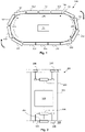
- Figure 1 shows a block diagram of an example of a print media transport apparatus 100 comprising a plurality of pallets 102 which, as will be described in greater detail in relation to the example of Figure 2 below, each have a self-propulsion mechanism, and are to support print media, i.e. a substrate to which a printed image, text or the like may be applied.
- print media may for example comprise a sheet material, such as paper, card stock, plastics, and the like, and may be rigid, substantially rigid or flexible.
- the pallets 102 circulate on an endless track 104.
- the track 104 comprises a printing zone 106, a descending zone 108 and an ascending zone 110.
- the pallets 102 circulate in a clockwise direction and the track 104 is substantially ovoid having a substantially horizontal printing zone 106 and a substantially horizontal return zone linking the descending zone 108 and the ascending zone 110.
- other (for example more convoluted) tracks may be provided.
- inks, toners and the like may be applied to media supported by one or several pallets 102 by an associated printer (not shown).
- pallets 102 on the printing zone 106 are controlled such that at least two pallets 102 move as a group across the printing zone 106 of the track 104 when supporting print media.
- Pallets 102 travelling on the printing zone 106 may thereby form a virtual table on which media is supported and carried relative to a printing mechanism of an associated printer.
- the printing mechanism may for example be associated with an ink supply and comprise a printhead mounted on a moveable carriage, an array of static printheads or the like.
- the printhead(s) may eject drops of ink through orifices or nozzles and towards a print media so as to print onto the media.
- the apparatus 100 further comprises a controller 112 to control the self-propulsion mechanisms of the pallets 102, such that a pallet 102 on the descending zone 108 is at least partially supported by another pallet 102 which is ahead on the track 104, and a pallet 102 on the ascending zone 110 is at least partially driven by pallet 102 which follows on the track 104.
- the controller 112 may comprise processing apparatus, such as a computer or the like, and may execute machine readable instructions in order to control the movement of the pallets 102.
- the controller 112 is shown as part of the apparatus 100.
- the controller 112 may be mounted on a pallet 102 (or the functions thereof may be distributed over several pallets 102), or the controller 112 may be separate, even remote, from the belt 104.
- Figure 2 shows an example of a pallet 102.
- the pallet 102 comprises a frame 202 and self-propulsion mechanism which comprises two linear motors 204 and control circuitry 208, which comprises motor drivers and some processing circuitry.
- the pallet 102 further comprises bearings 206 which are intended to run along the track 104 (which in this example comprises two spaced rails, which may be shaped so as to retain the bearings 206) supported by the frame 202 and driven by the motors 204.
- other propulsion mechanisms such as magnetic mechanisms or the like
- the motor 204 is powered using power collected by brushes 210, which interact with a power supply loop (not shown).
- the power may be provided in another manner, such as by a battery mounted on the pallet 102 or the like.
- the motors 204 are controlled by the control circuitry 208, itself controlled by the controller 112 of the print media transport apparatus 100.
- processing apparatus within the control circuitry 208 and the controller 112 communicate wirelessly. Such communication may comprise commands such as start and stop commands, requests for status updates, and the like.
- the status updates may for example to be to provide feedback to control loops and readings acquired by any sensors (for example hall effect sensors) mounted on a pallet 102.
- control circuitry 208 and the controller 112 act to control the motion of the pallets 102 such that, while a pallet 102 is on the printing zone 106, the motion (e.g. speed and/or location) is controlled to within a tolerance band.
- This may be a relatively tight tolerance band as accurate motion allows for predictable application of inks, toners and the like to media supported by the pallets 102.
- the location of a pallet 102 is controlled to within 10 microns while on the printing zone 106 of the track 104. This may be, for example, to ensure that the pallet 102 places media at an appropriate location for a drop of ink or the like to land, based on the time at which the drop is emitted.
- the pallets 102 are individually controlled while a pallet is on the printing zone 106 in a precision mode. However, outside this zone 106, for example while a pallet 102 is on the descending or ascending zones 108, 110, the motion may be allowed to vary outside the tolerance band.
- Figure 3 shows an example in which two pallets 300 are coupled together.
- the pallets 300 comprise two bar-like portions 302, the portions 302 being coupled in a substantially parallel configuration, the coupling allowing relative rotation between the portions 302.
- the pallets 300 are coupled to one another with a coupling allowing a variable spacing between the pallets 300.
- a slotted coupling 304 (for example, a metal coupling) connects pegs 306 provided on each pallet 300.
- the pegs 306 of the pallets 300 can be separated by the length of the slot in the slotted coupling 304, or the pallets 300 can move closer to one another until they are touching.
- the slotted coupling 304 also allows the pallets 300 to rotate relative to one another as they round the turns in the track 104.
- One of the portions 302 comprises a self-propulsion mechanism 308, the other being driven by the portion 302 having a self-propulsion mechanism 308.
- Such pallets 300 may be joined in an endless loop.
- the self-propulsion mechanisms of the pallets 102, 300 may be controlled by the controller 112 such that, while pallets 102, 300 are on the printing zone 106 of the track 104, the spacing remains constant (which allows for accurate media placement within the printing zone) and, while a pallet 102, 300 is on the descending 108 and ascending 110 zones of the track 104, the spacing is at a minimum (i.e. the pallets 102, 300 are tightly packed and are acting directly on one another).
- the pallets 102, 300 may also be tightly packed while on the substantially horizontal return zone of the track 104 such that the pallets 102, 300 on the descending zone 108 can act on the pallets 102, 300 on the ascending zone 110 (and vice versa) indirectly, the ascending pallets 102, 300 acting as a counterbalance to the descending pallets 102, 300, as further explained below.
- Control of the pallets 102, 300 may be carried out as shown in the flow chart of Figure 4 .
- a pallet 102, 300 is on the printing zone 106 of the track 104, it is driven with a first driving force provided by a self-propulsion mechanism of the pallet 102, 300 (block 402).
- a retarding force is applied by at least one other pallet 102, 300 on the track 104 (bock 404).
- a second driving force is provided by at least one other pallet 102, 300 on the track 104 (block 406). This second driving force may be provided gravity acting on at least one pallet 102, 300 on the descending zone 108 of the track 104.
- the retarding force and/or the second driving force may be transmitted via at least one intermediate pallet 102, 300 between the pallet 102, 300 on the ascending zone 110 of the track 104 and the pallet 102, 300 on the descending zone 108 of the track 104 (i.e. via at least one intermediate pallet 102, 300 on the substantially horizontal return zone of the track 104).
- FIGs 5a and 5b compare the current delivered to a self-propulsion mechanism according to two schemes for driving a pallet 102, 300.
- each pallet 102, 300 is driven by its self-propulsion mechanism in isolation.
- the current shows a peak as the pallet 102, 300 is driven to climb and overcome gravity.
- the current shows a dip as gravity is resisted.
- Figure 5b shows the current delivered to drive a pallet 102, 300 according to examples of the methods set out herein, for example according to the flow chart of Figure 4 .
- the current variability is much lower- the average current being supplied in each zone 106, 108, 110 is more similar, in particular in the ascending 108 and descending 110 zones, being substantially constant, or equal between zones.
- the current (and power) supplied to a self-propulsion mechanism of an individual pallet 102, 300 on the ascending zone 110 of track 104 is insufficient to allow that pallet 102, 300 to climb the ascending zone 110 of track 104 (an additional driving force supplied by the action of a descending pallet 102, 300 is employed).
- the method of Figure 4 may be achieved by supplying power or current to the propulsion mechanism of each pallet 102, 300 at a substantially constant average level for all zones of the track 104.
- the actual variability of the current will dependent on factors such as the friction encountered in an apparatus. However, in some examples, the current may be within a range of 50% of the average current.
- the average current supplied while a pallet traverses a particular zone is substantially equal for all zones (or at least for the ascending and descending zones 108, 110). Effectively, ascending pallets 102, 300 will be pushed by following pallets 102, 300 and descending pallets 102, 300 will lean on preceding pallets 102, 300, which therefore provide a retarding force (or counterweight). This balances the driving currents across the phases of motion around the track 104.
- a first, second and third pallet 102, 300 are provided on an endless track 104 of a print media transport apparatus 100.
- the first pallet 102, 300 precedes the second pallet 102, 300 and the second pallet 102, 300 precedes the third pallet 102, 300.
- a self-propulsion mechanism of each of the first, second and third pallet 102, 300 is controlled such that, on a descending zone 108 of the track 104, the first pallet 102, 300 at least partially supports the second pallet 102, 300 and on an ascending zone 110 of the track 104, the third pallet 102, 300 at least partially drives the second pallet 102, 300.
- the pallet movements may be accurately controlled while a pallet 102, 300 is on the printing zone 106 of the track 104, this may be less of a concern in other zones of the track 104.
- Examples in the present disclosure can be provided as methods, systems or machine readable instructions, such as any combination of software, hardware, firmware or the like, which may for example be executed by the controller 112 or the control circuitry 208.
- Such machine readable instructions may be included on a computer readable storage medium (including but is not limited to disc storage, CD-ROM, optical storage, etc.) having computer readable program codes therein or thereon.
- the machine readable instructions may, for example, be executed by a general purpose computer, a special purpose computer, an embedded processor or processors of other programmable data processing devices to realize the functions of the controller 112 and/or control circuitry 208 described in the description and diagrams.
- a processor or processing apparatus may execute the machine readable instructions.
- modules of the apparatus and devices may be implemented by a processor executing machine readable instructions stored in a memory, or a processor operating in accordance with instructions embedded in logic circuitry.
- the term 'processor' is to be interpreted broadly to include a CPU, processing unit, ASIC, logic unit, or programmable gate array etc.
- the methods and functional modules may all be performed by a single processor or divided amongst several processors.
- teachings herein may be implemented in the form of a computer software product, the computer software product being stored in a storage medium and comprising a plurality of instructions for making a computer device implement the methods recited in the examples of the present disclosure.
Landscapes
- Engineering & Computer Science (AREA)
- Mechanical Engineering (AREA)
- Ink Jet (AREA)
- Feeding Of Articles By Means Other Than Belts Or Rollers (AREA)
- Dot-Matrix Printers And Others (AREA)
Claims (5)
- Druckmedientransportvorrichtung (100), die Folgendes umfasst:eine Endlosbahn (104), die eine Druckzone (106), eine absteigende Zone (108) und eine aufsteigende Zone (110) umfasst,mehrere Paletten (102, 300), die auf der Endlosbahn (104) zirkulieren, wobei jede Palette (102, 300) der mehreren Paletten (102, 300) einen Selbstantriebsmechanismus umfasst und eine obere Oberfläche, um Druckmedien zu tragen, aufweist, wobei die mehreren Paletten (102, 300) eine Endlosbahn ausbilden, wobei angrenzende Paletten (102, 300) durch eine Kopplung (304), die einen variablen Abstand zwischen den angrenzenden Paletten (102, 300) ermöglicht, verknüpft sind, wobei während sich eine Palette (102, 300) auf der Druckzone (106) der Bahn (104) befindet, der Abstand konstant bleibt, und während sich eine Palette (102, 300) auf den absteigenden und aufsteigenden Zonen (110) der Bahn (104) befindet, der Abstand auf einem derartigen Minimum ist, dass die Paletten (102, 300) dicht gepackt sind und direkt aufeinander wirken, undeine Steuerung (112), die den Selbstantriebsmechanismus jeder Palette (102, 300) steuert.
- Vorrichtung nach Anspruch 1, wobei die Kopplung (304), die angrenzende Paletten (102, 300) verbindet, eine geschlitzte Kopplung (304) ist, wobei die geschlitzte Kopplung (304) Stifte auf jeder angrenzenden Palette (102, 300) verbindet, wobei die Stifte der angrenzenden Paletten (300) durch die Länge des Schlitzes in der geschlitzten Kopplung (304) getrennt werden können oder sich die angrenzende Paletten (300) bis zu dem Berühren näher zueinander bewegen können und wobei die geschlitzte Kopplung (304) den Paletten ebenso ermöglicht, sich relativ zueinander zu drehen, während sie die Windungen der Bahn (104) umrunden.
- Vorrichtung nach Anspruch 1 oder 2, wobei der Selbstantriebsmechanismus jeder Palette (102, 300) eine im Wesentlichen konstante durchschnittliche Leistungsrate aufweist, die sowohl in der absteigenden Zone (108) als auch in der aufsteigenden Zone (110) zugeführt wird.
- Vorrichtung nach Anspruch 3, wobei die Leistung, die einem Selbstantriebsmechanismus (308) einer einzelnen Palette (102, 300) auf der ansteigenden Zone (110) der Bahn (104) zugeführt wird, unzureichend ist, um dieser Palette (102, 300) zu ermöglichen, die aufsteigende Zone (110) der Bahn (104) ohne eine treibende Kraft von einer absteigenden Palette (102, 300) zu erklimmen.
- Druckmedientransportvorrichtung (100) nach einem beliebigen vorhergehenden Anspruch, wobei die jedem Antriebsmechanismus zugeführte Leistung auf einem im Wesentlichen konstanten Durchschnittsniveau für die gesamten Zonen der Bahn (104) liegt; und
bei Verwendung der Vorrichtung Paletten (102, 300) in der aufsteigenden Zone (110) durch nachfolgende Paletten (102, 300) geschoben werden und Paletten (102, 300) in der absteigenden Zone (108) auf vorhergehenden Paletten (102, 300) lehnen, die eine Verzögerungskraft bereitstellen.
Priority Applications (1)
| Application Number | Priority Date | Filing Date | Title |
|---|---|---|---|
| EP18154103.8A EP3342597B1 (de) | 2015-07-31 | 2015-07-31 | Druckmedientransportvorrichtung |
Applications Claiming Priority (2)
| Application Number | Priority Date | Filing Date | Title |
|---|---|---|---|
| EP15179407.0A EP3124263B1 (de) | 2015-07-31 | 2015-07-31 | Druckmedientransportvorrichtung |
| EP18154103.8A EP3342597B1 (de) | 2015-07-31 | 2015-07-31 | Druckmedientransportvorrichtung |
Related Parent Applications (2)
| Application Number | Title | Priority Date | Filing Date |
|---|---|---|---|
| EP15179407.0A Division-Into EP3124263B1 (de) | 2015-07-31 | 2015-07-31 | Druckmedientransportvorrichtung |
| EP15179407.0A Division EP3124263B1 (de) | 2015-07-31 | 2015-07-31 | Druckmedientransportvorrichtung |
Publications (2)
| Publication Number | Publication Date |
|---|---|
| EP3342597A1 EP3342597A1 (de) | 2018-07-04 |
| EP3342597B1 true EP3342597B1 (de) | 2022-04-06 |
Family
ID=53794067
Family Applications (2)
| Application Number | Title | Priority Date | Filing Date |
|---|---|---|---|
| EP18154103.8A Active EP3342597B1 (de) | 2015-07-31 | 2015-07-31 | Druckmedientransportvorrichtung |
| EP15179407.0A Active EP3124263B1 (de) | 2015-07-31 | 2015-07-31 | Druckmedientransportvorrichtung |
Family Applications After (1)
| Application Number | Title | Priority Date | Filing Date |
|---|---|---|---|
| EP15179407.0A Active EP3124263B1 (de) | 2015-07-31 | 2015-07-31 | Druckmedientransportvorrichtung |
Country Status (4)
| Country | Link |
|---|---|
| US (2) | US9796548B2 (de) |
| EP (2) | EP3342597B1 (de) |
| JP (2) | JP6336527B2 (de) |
| CN (1) | CN106394011B (de) |
Families Citing this family (4)
| Publication number | Priority date | Publication date | Assignee | Title |
|---|---|---|---|---|
| EP3342597B1 (de) * | 2015-07-31 | 2022-04-06 | HP Scitex Ltd | Druckmedientransportvorrichtung |
| US11072398B2 (en) * | 2016-08-12 | 2021-07-27 | Illinois Tool Works Inc. | Apparatuses and methods for high-resolution printing |
| EP3315309B1 (de) * | 2016-10-31 | 2021-08-04 | HP Scitex Ltd | Vakuum in einem palettenförderer für ein drucksystem |
| CN107284046A (zh) * | 2017-07-30 | 2017-10-24 | 合肥岸鲁意科技有限公司 | 一种循环转动双织物同时印花数字喷墨印花机和印花方法 |
Family Cites Families (15)
| Publication number | Priority date | Publication date | Assignee | Title |
|---|---|---|---|---|
| US6126384A (en) | 1995-06-07 | 2000-10-03 | Standard Duplicating Machines Corporation | Paper set feeding |
| US5921368A (en) | 1997-02-25 | 1999-07-13 | Knight Industries, Inc. | Linked carrier gravity conveyor |
| JP4323758B2 (ja) * | 2002-05-24 | 2009-09-02 | 日本電産サンキョー株式会社 | ワーク搬送システム |
| JP2003345212A (ja) * | 2002-05-30 | 2003-12-03 | Ricoh Co Ltd | 画像形成装置 |
| JP2004299884A (ja) | 2003-03-31 | 2004-10-28 | Fuji Photo Film Co Ltd | シート排出装置 |
| JP5196918B2 (ja) * | 2007-08-30 | 2013-05-15 | 株式会社ミマキエンジニアリング | 印刷装置の製造方法 |
| JP5016539B2 (ja) * | 2008-03-31 | 2012-09-05 | 大日本スクリーン製造株式会社 | 記録媒体搬送装置 |
| EP2106916B1 (de) * | 2008-03-31 | 2011-05-04 | Dainippon Screen Mfg., Co., Ltd. | Bildaufzeichnungsvorrichtung |
| JP5037431B2 (ja) * | 2008-05-28 | 2012-09-26 | 大日本スクリーン製造株式会社 | 画像記録装置における記録媒体搬送装置 |
| JP5258630B2 (ja) * | 2009-03-04 | 2013-08-07 | 富士フイルム株式会社 | 搬送装置及び液体吐出装置 |
| WO2012108870A1 (en) * | 2011-02-10 | 2012-08-16 | Hewlett-Packard Development Company, L.P. | Media transport assembly |
| US9056620B2 (en) | 2012-12-06 | 2015-06-16 | Gary D. Copus | Material handling and load conveyance system |
| EP3018081B1 (de) * | 2014-11-06 | 2017-08-02 | Hewlett-Packard Industrial Printing Ltd. | Palettenförderer für Drucker |
| JP6607343B2 (ja) * | 2015-03-30 | 2019-11-20 | パナソニックIpマネジメント株式会社 | 印刷装置、および薄膜印刷体の製造方法 |
| EP3342597B1 (de) * | 2015-07-31 | 2022-04-06 | HP Scitex Ltd | Druckmedientransportvorrichtung |
-
2015
- 2015-07-31 EP EP18154103.8A patent/EP3342597B1/de active Active
- 2015-07-31 EP EP15179407.0A patent/EP3124263B1/de active Active
-
2016
- 2016-07-27 US US15/221,469 patent/US9796548B2/en active Active
- 2016-07-29 CN CN201610610172.XA patent/CN106394011B/zh active Active
- 2016-07-29 JP JP2016149642A patent/JP6336527B2/ja active Active
-
2017
- 2017-09-08 US US15/698,831 patent/US10189663B2/en active Active
-
2018
- 2018-05-01 JP JP2018088202A patent/JP6684305B2/ja active Active
Also Published As
| Publication number | Publication date |
|---|---|
| EP3124263B1 (de) | 2018-05-16 |
| CN106394011A (zh) | 2017-02-15 |
| JP2018158841A (ja) | 2018-10-11 |
| US9796548B2 (en) | 2017-10-24 |
| EP3124263A1 (de) | 2017-02-01 |
| JP6336527B2 (ja) | 2018-06-06 |
| EP3342597A1 (de) | 2018-07-04 |
| US20170029228A1 (en) | 2017-02-02 |
| US10189663B2 (en) | 2019-01-29 |
| US20170369263A1 (en) | 2017-12-28 |
| JP2017036150A (ja) | 2017-02-16 |
| CN106394011B (zh) | 2019-12-17 |
| JP6684305B2 (ja) | 2020-04-22 |
Similar Documents
| Publication | Publication Date | Title |
|---|---|---|
| US10189663B2 (en) | Print media transport apparatus | |
| US9421795B2 (en) | Pallet conveyors for printers | |
| US8888271B2 (en) | Air bearing substrate media transport | |
| US9067408B2 (en) | Printing media supportable on movable pallets | |
| CN101171139B (zh) | 用于数字打印机中的打印头托架的免受力支撑框架 | |
| CN101837687A (zh) | 图像形成设备 | |
| CN1611367A (zh) | 打印机和进纸控制器 | |
| CN101823642A (zh) | 浮动型自动张紧送料装置 | |
| EP1705024A3 (de) | Tintenstrahlaufzeichnungsgerät mit Reinigungsvorrichtung für Förderband | |
| EP1126978B1 (de) | Druckverfahren | |
| US9284140B2 (en) | Belt conveyance device, media conveyance device, and printer | |
| CN109153270A (zh) | 用于印刷印刷品的设备和方法 | |
| CN105197520A (zh) | 一种柔性车身存储输送系统 | |
| EP3199359A3 (de) | Steuerungsanordnung | |
| CN104555533A (zh) | 间歇机机头机组间歇印刷进纸出纸连续运转装置 | |
| KR930007681A (ko) | 원통형 합성수지용기의 표면 인쇄방법 및 그 장치 | |
| JP2008308249A (ja) | 無端ベルトの蛇行補正装置、ベルト搬送装置及びプリンタ | |
| JP2019010742A (ja) | 液体噴射装置 | |
| CN206551478U (zh) | 一种滑动式运动的打印头结构 | |
| CN203753795U (zh) | 传动带运输机 | |
| JP2013215913A (ja) | 記録装置、記録装置の制御方法および記録装置の制御プログラム | |
| JP2013166289A (ja) | 記録装置および記録装置の制御方法 | |
| JP2010089427A (ja) | 記録装置 | |
| TH1801006096A (th) | การควบคุมของการทำการพิมพ์ของหัวพิมพ์ในเครื่องพิมพ์ดิจิทัล |
Legal Events
| Date | Code | Title | Description |
|---|---|---|---|
| PUAI | Public reference made under article 153(3) epc to a published international application that has entered the european phase |
Free format text: ORIGINAL CODE: 0009012 |
|
| STAA | Information on the status of an ep patent application or granted ep patent |
Free format text: STATUS: REQUEST FOR EXAMINATION WAS MADE |
|
| 17P | Request for examination filed |
Effective date: 20180130 |
|
| AC | Divisional application: reference to earlier application |
Ref document number: 3124263 Country of ref document: EP Kind code of ref document: P |
|
| AK | Designated contracting states |
Kind code of ref document: A1 Designated state(s): AL AT BE BG CH CY CZ DE DK EE ES FI FR GB GR HR HU IE IS IT LI LT LU LV MC MK MT NL NO PL PT RO RS SE SI SK SM TR |
|
| STAA | Information on the status of an ep patent application or granted ep patent |
Free format text: STATUS: EXAMINATION IS IN PROGRESS |
|
| 17Q | First examination report despatched |
Effective date: 20200723 |
|
| GRAP | Despatch of communication of intention to grant a patent |
Free format text: ORIGINAL CODE: EPIDOSNIGR1 |
|
| STAA | Information on the status of an ep patent application or granted ep patent |
Free format text: STATUS: GRANT OF PATENT IS INTENDED |
|
| INTG | Intention to grant announced |
Effective date: 20211214 |
|
| GRAS | Grant fee paid |
Free format text: ORIGINAL CODE: EPIDOSNIGR3 |
|
| GRAA | (expected) grant |
Free format text: ORIGINAL CODE: 0009210 |
|
| STAA | Information on the status of an ep patent application or granted ep patent |
Free format text: STATUS: THE PATENT HAS BEEN GRANTED |
|
| AC | Divisional application: reference to earlier application |
Ref document number: 3124263 Country of ref document: EP Kind code of ref document: P |
|
| AK | Designated contracting states |
Kind code of ref document: B1 Designated state(s): AL AT BE BG CH CY CZ DE DK EE ES FI FR GB GR HR HU IE IS IT LI LT LU LV MC MK MT NL NO PL PT RO RS SE SI SK SM TR |
|
| REG | Reference to a national code |
Ref country code: GB Ref legal event code: FG4D |
|
| REG | Reference to a national code |
Ref country code: CH Ref legal event code: EP |
|
| REG | Reference to a national code |
Ref country code: AT Ref legal event code: REF Ref document number: 1480974 Country of ref document: AT Kind code of ref document: T Effective date: 20220415 |
|
| REG | Reference to a national code |
Ref country code: IE Ref legal event code: FG4D |
|
| REG | Reference to a national code |
Ref country code: DE Ref legal event code: R096 Ref document number: 602015078139 Country of ref document: DE |
|
| REG | Reference to a national code |
Ref country code: LT Ref legal event code: MG9D |
|
| REG | Reference to a national code |
Ref country code: NL Ref legal event code: MP Effective date: 20220406 |
|
| REG | Reference to a national code |
Ref country code: AT Ref legal event code: MK05 Ref document number: 1480974 Country of ref document: AT Kind code of ref document: T Effective date: 20220406 |
|
| PG25 | Lapsed in a contracting state [announced via postgrant information from national office to epo] |
Ref country code: NL Free format text: LAPSE BECAUSE OF FAILURE TO SUBMIT A TRANSLATION OF THE DESCRIPTION OR TO PAY THE FEE WITHIN THE PRESCRIBED TIME-LIMIT Effective date: 20220406 |
|
| PG25 | Lapsed in a contracting state [announced via postgrant information from national office to epo] |
Ref country code: SE Free format text: LAPSE BECAUSE OF FAILURE TO SUBMIT A TRANSLATION OF THE DESCRIPTION OR TO PAY THE FEE WITHIN THE PRESCRIBED TIME-LIMIT Effective date: 20220406 Ref country code: PT Free format text: LAPSE BECAUSE OF FAILURE TO SUBMIT A TRANSLATION OF THE DESCRIPTION OR TO PAY THE FEE WITHIN THE PRESCRIBED TIME-LIMIT Effective date: 20220808 Ref country code: NO Free format text: LAPSE BECAUSE OF FAILURE TO SUBMIT A TRANSLATION OF THE DESCRIPTION OR TO PAY THE FEE WITHIN THE PRESCRIBED TIME-LIMIT Effective date: 20220706 Ref country code: LT Free format text: LAPSE BECAUSE OF FAILURE TO SUBMIT A TRANSLATION OF THE DESCRIPTION OR TO PAY THE FEE WITHIN THE PRESCRIBED TIME-LIMIT Effective date: 20220406 Ref country code: HR Free format text: LAPSE BECAUSE OF FAILURE TO SUBMIT A TRANSLATION OF THE DESCRIPTION OR TO PAY THE FEE WITHIN THE PRESCRIBED TIME-LIMIT Effective date: 20220406 Ref country code: GR Free format text: LAPSE BECAUSE OF FAILURE TO SUBMIT A TRANSLATION OF THE DESCRIPTION OR TO PAY THE FEE WITHIN THE PRESCRIBED TIME-LIMIT Effective date: 20220707 Ref country code: FI Free format text: LAPSE BECAUSE OF FAILURE TO SUBMIT A TRANSLATION OF THE DESCRIPTION OR TO PAY THE FEE WITHIN THE PRESCRIBED TIME-LIMIT Effective date: 20220406 Ref country code: ES Free format text: LAPSE BECAUSE OF FAILURE TO SUBMIT A TRANSLATION OF THE DESCRIPTION OR TO PAY THE FEE WITHIN THE PRESCRIBED TIME-LIMIT Effective date: 20220406 Ref country code: BG Free format text: LAPSE BECAUSE OF FAILURE TO SUBMIT A TRANSLATION OF THE DESCRIPTION OR TO PAY THE FEE WITHIN THE PRESCRIBED TIME-LIMIT Effective date: 20220706 Ref country code: AT Free format text: LAPSE BECAUSE OF FAILURE TO SUBMIT A TRANSLATION OF THE DESCRIPTION OR TO PAY THE FEE WITHIN THE PRESCRIBED TIME-LIMIT Effective date: 20220406 |
|
| PG25 | Lapsed in a contracting state [announced via postgrant information from national office to epo] |
Ref country code: RS Free format text: LAPSE BECAUSE OF FAILURE TO SUBMIT A TRANSLATION OF THE DESCRIPTION OR TO PAY THE FEE WITHIN THE PRESCRIBED TIME-LIMIT Effective date: 20220406 Ref country code: PL Free format text: LAPSE BECAUSE OF FAILURE TO SUBMIT A TRANSLATION OF THE DESCRIPTION OR TO PAY THE FEE WITHIN THE PRESCRIBED TIME-LIMIT Effective date: 20220406 Ref country code: LV Free format text: LAPSE BECAUSE OF FAILURE TO SUBMIT A TRANSLATION OF THE DESCRIPTION OR TO PAY THE FEE WITHIN THE PRESCRIBED TIME-LIMIT Effective date: 20220406 Ref country code: IS Free format text: LAPSE BECAUSE OF FAILURE TO SUBMIT A TRANSLATION OF THE DESCRIPTION OR TO PAY THE FEE WITHIN THE PRESCRIBED TIME-LIMIT Effective date: 20220806 |
|
| REG | Reference to a national code |
Ref country code: DE Ref legal event code: R097 Ref document number: 602015078139 Country of ref document: DE |
|
| PG25 | Lapsed in a contracting state [announced via postgrant information from national office to epo] |
Ref country code: SM Free format text: LAPSE BECAUSE OF FAILURE TO SUBMIT A TRANSLATION OF THE DESCRIPTION OR TO PAY THE FEE WITHIN THE PRESCRIBED TIME-LIMIT Effective date: 20220406 Ref country code: SK Free format text: LAPSE BECAUSE OF FAILURE TO SUBMIT A TRANSLATION OF THE DESCRIPTION OR TO PAY THE FEE WITHIN THE PRESCRIBED TIME-LIMIT Effective date: 20220406 Ref country code: RO Free format text: LAPSE BECAUSE OF FAILURE TO SUBMIT A TRANSLATION OF THE DESCRIPTION OR TO PAY THE FEE WITHIN THE PRESCRIBED TIME-LIMIT Effective date: 20220406 Ref country code: EE Free format text: LAPSE BECAUSE OF FAILURE TO SUBMIT A TRANSLATION OF THE DESCRIPTION OR TO PAY THE FEE WITHIN THE PRESCRIBED TIME-LIMIT Effective date: 20220406 Ref country code: DK Free format text: LAPSE BECAUSE OF FAILURE TO SUBMIT A TRANSLATION OF THE DESCRIPTION OR TO PAY THE FEE WITHIN THE PRESCRIBED TIME-LIMIT Effective date: 20220406 Ref country code: CZ Free format text: LAPSE BECAUSE OF FAILURE TO SUBMIT A TRANSLATION OF THE DESCRIPTION OR TO PAY THE FEE WITHIN THE PRESCRIBED TIME-LIMIT Effective date: 20220406 |
|
| PLBE | No opposition filed within time limit |
Free format text: ORIGINAL CODE: 0009261 |
|
| STAA | Information on the status of an ep patent application or granted ep patent |
Free format text: STATUS: NO OPPOSITION FILED WITHIN TIME LIMIT |
|
| PG25 | Lapsed in a contracting state [announced via postgrant information from national office to epo] |
Ref country code: MC Free format text: LAPSE BECAUSE OF FAILURE TO SUBMIT A TRANSLATION OF THE DESCRIPTION OR TO PAY THE FEE WITHIN THE PRESCRIBED TIME-LIMIT Effective date: 20220406 |
|
| REG | Reference to a national code |
Ref country code: CH Ref legal event code: PL |
|
| 26N | No opposition filed |
Effective date: 20230110 |
|
| REG | Reference to a national code |
Ref country code: BE Ref legal event code: MM Effective date: 20220731 |
|
| PG25 | Lapsed in a contracting state [announced via postgrant information from national office to epo] |
Ref country code: AL Free format text: LAPSE BECAUSE OF FAILURE TO SUBMIT A TRANSLATION OF THE DESCRIPTION OR TO PAY THE FEE WITHIN THE PRESCRIBED TIME-LIMIT Effective date: 20220406 |
|
| PG25 | Lapsed in a contracting state [announced via postgrant information from national office to epo] |
Ref country code: LU Free format text: LAPSE BECAUSE OF NON-PAYMENT OF DUE FEES Effective date: 20220731 Ref country code: LI Free format text: LAPSE BECAUSE OF NON-PAYMENT OF DUE FEES Effective date: 20220731 Ref country code: CH Free format text: LAPSE BECAUSE OF NON-PAYMENT OF DUE FEES Effective date: 20220731 |
|
| PG25 | Lapsed in a contracting state [announced via postgrant information from national office to epo] |
Ref country code: SI Free format text: LAPSE BECAUSE OF FAILURE TO SUBMIT A TRANSLATION OF THE DESCRIPTION OR TO PAY THE FEE WITHIN THE PRESCRIBED TIME-LIMIT Effective date: 20220406 Ref country code: BE Free format text: LAPSE BECAUSE OF NON-PAYMENT OF DUE FEES Effective date: 20220731 |
|
| PG25 | Lapsed in a contracting state [announced via postgrant information from national office to epo] |
Ref country code: IE Free format text: LAPSE BECAUSE OF NON-PAYMENT OF DUE FEES Effective date: 20220731 |
|
| PGFP | Annual fee paid to national office [announced via postgrant information from national office to epo] |
Ref country code: FR Payment date: 20230621 Year of fee payment: 9 |
|
| PGFP | Annual fee paid to national office [announced via postgrant information from national office to epo] |
Ref country code: GB Payment date: 20230620 Year of fee payment: 9 |
|
| PG25 | Lapsed in a contracting state [announced via postgrant information from national office to epo] |
Ref country code: IT Free format text: LAPSE BECAUSE OF FAILURE TO SUBMIT A TRANSLATION OF THE DESCRIPTION OR TO PAY THE FEE WITHIN THE PRESCRIBED TIME-LIMIT Effective date: 20220406 |
|
| PG25 | Lapsed in a contracting state [announced via postgrant information from national office to epo] |
Ref country code: HU Free format text: LAPSE BECAUSE OF FAILURE TO SUBMIT A TRANSLATION OF THE DESCRIPTION OR TO PAY THE FEE WITHIN THE PRESCRIBED TIME-LIMIT; INVALID AB INITIO Effective date: 20150731 |
|
| PG25 | Lapsed in a contracting state [announced via postgrant information from national office to epo] |
Ref country code: MK Free format text: LAPSE BECAUSE OF FAILURE TO SUBMIT A TRANSLATION OF THE DESCRIPTION OR TO PAY THE FEE WITHIN THE PRESCRIBED TIME-LIMIT Effective date: 20220406 Ref country code: CY Free format text: LAPSE BECAUSE OF FAILURE TO SUBMIT A TRANSLATION OF THE DESCRIPTION OR TO PAY THE FEE WITHIN THE PRESCRIBED TIME-LIMIT Effective date: 20220406 |
|
| PG25 | Lapsed in a contracting state [announced via postgrant information from national office to epo] |
Ref country code: TR Free format text: LAPSE BECAUSE OF FAILURE TO SUBMIT A TRANSLATION OF THE DESCRIPTION OR TO PAY THE FEE WITHIN THE PRESCRIBED TIME-LIMIT Effective date: 20220406 |
|
| PG25 | Lapsed in a contracting state [announced via postgrant information from national office to epo] |
Ref country code: MT Free format text: LAPSE BECAUSE OF FAILURE TO SUBMIT A TRANSLATION OF THE DESCRIPTION OR TO PAY THE FEE WITHIN THE PRESCRIBED TIME-LIMIT Effective date: 20220406 |
|
| PG25 | Lapsed in a contracting state [announced via postgrant information from national office to epo] |
Ref country code: BG Free format text: LAPSE BECAUSE OF FAILURE TO SUBMIT A TRANSLATION OF THE DESCRIPTION OR TO PAY THE FEE WITHIN THE PRESCRIBED TIME-LIMIT Effective date: 20220406 |
|
| PG25 | Lapsed in a contracting state [announced via postgrant information from national office to epo] |
Ref country code: BG Free format text: LAPSE BECAUSE OF FAILURE TO SUBMIT A TRANSLATION OF THE DESCRIPTION OR TO PAY THE FEE WITHIN THE PRESCRIBED TIME-LIMIT Effective date: 20220406 |
|
| GBPC | Gb: european patent ceased through non-payment of renewal fee |
Effective date: 20240731 |
|
| PG25 | Lapsed in a contracting state [announced via postgrant information from national office to epo] |
Ref country code: FR Free format text: LAPSE BECAUSE OF NON-PAYMENT OF DUE FEES Effective date: 20240731 |
|
| PG25 | Lapsed in a contracting state [announced via postgrant information from national office to epo] |
Ref country code: GB Free format text: LAPSE BECAUSE OF NON-PAYMENT OF DUE FEES Effective date: 20240731 |
|
| PGFP | Annual fee paid to national office [announced via postgrant information from national office to epo] |
Ref country code: DE Payment date: 20250620 Year of fee payment: 11 |