EP3342637A1 - Console de support de transit pour structure tubulaire cylindrique - Google Patents
Console de support de transit pour structure tubulaire cylindrique Download PDFInfo
- Publication number
- EP3342637A1 EP3342637A1 EP17209622.4A EP17209622A EP3342637A1 EP 3342637 A1 EP3342637 A1 EP 3342637A1 EP 17209622 A EP17209622 A EP 17209622A EP 3342637 A1 EP3342637 A1 EP 3342637A1
- Authority
- EP
- European Patent Office
- Prior art keywords
- bracket
- slots
- support
- support bracket
- plug plates
- Prior art date
- Legal status (The legal status is an assumption and is not a legal conclusion. Google has not performed a legal analysis and makes no representation as to the accuracy of the status listed.)
- Withdrawn
Links
Images


Classifications
-
- B—PERFORMING OPERATIONS; TRANSPORTING
- B60—VEHICLES IN GENERAL
- B60P—VEHICLES ADAPTED FOR LOAD TRANSPORTATION OR TO TRANSPORT, TO CARRY, OR TO COMPRISE SPECIAL LOADS OR OBJECTS
- B60P7/00—Securing or covering of load on vehicles
- B60P7/06—Securing of load
- B60P7/08—Securing to the vehicle floor or sides
- B60P7/12—Securing to the vehicle floor or sides the load being tree-trunks, beams, drums, tubes, or the like
-
- B—PERFORMING OPERATIONS; TRANSPORTING
- B60—VEHICLES IN GENERAL
- B60P—VEHICLES ADAPTED FOR LOAD TRANSPORTATION OR TO TRANSPORT, TO CARRY, OR TO COMPRISE SPECIAL LOADS OR OBJECTS
- B60P3/00—Vehicles adapted to transport, to carry or to comprise special loads or objects
- B60P3/40—Vehicles adapted to transport, to carry or to comprise special loads or objects for carrying long loads, e.g. with separate wheeled load supporting elements
-
- F—MECHANICAL ENGINEERING; LIGHTING; HEATING; WEAPONS; BLASTING
- F03—MACHINES OR ENGINES FOR LIQUIDS; WIND, SPRING, OR WEIGHT MOTORS; PRODUCING MECHANICAL POWER OR A REACTIVE PROPULSIVE THRUST, NOT OTHERWISE PROVIDED FOR
- F03D—WIND MOTORS
- F03D13/00—Assembly, mounting or commissioning of wind motors; Arrangements specially adapted for transporting wind motor components
- F03D13/40—Arrangements or methods specially adapted for transporting wind motor components
-
- Y—GENERAL TAGGING OF NEW TECHNOLOGICAL DEVELOPMENTS; GENERAL TAGGING OF CROSS-SECTIONAL TECHNOLOGIES SPANNING OVER SEVERAL SECTIONS OF THE IPC; TECHNICAL SUBJECTS COVERED BY FORMER USPC CROSS-REFERENCE ART COLLECTIONS [XRACs] AND DIGESTS
- Y02—TECHNOLOGIES OR APPLICATIONS FOR MITIGATION OR ADAPTATION AGAINST CLIMATE CHANGE
- Y02E—REDUCTION OF GREENHOUSE GAS [GHG] EMISSIONS, RELATED TO ENERGY GENERATION, TRANSMISSION OR DISTRIBUTION
- Y02E10/00—Energy generation through renewable energy sources
- Y02E10/70—Wind energy
- Y02E10/72—Wind turbines with rotation axis in wind direction
Definitions
- This invention relates to a system for supporting cylindrical tubular structure for example sections of the support structure for wind turbines during transit.
- Support towers for wind turbines generally consist of plural sections of cylindrical tubular sections that have annular flanges with apertures that allow for on-site assembly.
- the individual sections are transported to the assembly site by ships, railcars, and or trucks. During transit it is necessary to secure the sections to the particular mode of transportation.
- brackets are used that include elongated slots through which bolts are placed.
- the bolts extend through the aperture in the annular flange of the tower sections and nuts are then attached to the bolts.
- a significant amount of torque for example up to sixty percent of the bolt material yield point is required to secure the bracket to the flange because the slots are formed to accommodate several different diameters of bolts.
- the amount of torque required increases the difficulty in assembly of the support brackets and may lead to failure of the bolts. It would be desirable to design a bracket and support system that did not require such a high level of torque to be applied to the bolt in order to secure the tower section to the bracket assembly and to allow a single bracket assembly to be modified to accommodate a plurality of tubular sizes.
- a bracket includes a main body that includes upper and lower support surfaces and a vertical plate member extending between the upper and lower support surfaces.
- the plate includes a plurality of slots that are adapted to tightly receive a flange bolt plug plate that is pre-drilled to be used with a specified tower section that has a specified diameter and hole size in the circular flange. This considerably reduces the amount of torque required to secure the tower section to the bracket.
- the bolt may be tightened to a snug tightened condition which is attained with a few impacts of an impact wrench or the full efforts of a worker using an ordinary spud wrench.
- a support bracket for a tubular member comprising: a top portion, a bottom portion, a plate member having a plurality of arcuately spaced slots, said plate member extending between and attached to the top and bottom portions, and a plurality of plug plates having at least one aperture adapted to fit within the slots.
- a bracket support system for tubulars comprising: a lower bracket having a top portion and a bottom portion, a plate having a plurality of radially spaced slots extending therethrough and connected to the upper and lower portion, a plurality of plug plates adapted to fit within the slots, the plug plates having at least one aperture, an end portion at each end of the lower bracket, the end portion including a socket for receiving a support post, and an upper bracket having a top portion and bottom portion , a plate having a plurality of radially spaced slots extending therethrough and connected to the upper and lower portions, a plurality of plug plates adapted to fit within the slots, the plug plates having at least one aperture, an end portion at each end of the upper bracket, each end portion including a socket for receiving a support post, and two support posts, adapted to positioned within the sockets of the lower and upper brackets.
- a similar upper support bracket with an addition lower bracket can be used when it is desired to stack the tower sections as it will be discussed below.
- the bracket system is a universal application in that individual flange bolt plug plates can be fabricated and selected for insertion into the slots according to the specific dimension of the section being transported.
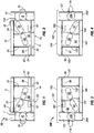
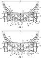
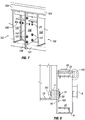
- Figures 1-9 illustrates an embodiment of the invention as herein described.
- Figure 10 illustrates a stacking embodiment for two tubulars 13 which may be sections of a support column for a wind turbine.
- the system of figure 10 includes four lower brackets 10 and two upper brackets 100.
- the lower and upper brackets are secured to each other by a pair of support columns 200 and 201 which are adapted to be positioned within complimentary shaped sockets 21, 22 as shown in figures 1, 2 and 5 provided in the lower bracket 10 and sockets 203, 204 as shown in figure 3 and 4 provided in the upper bracket 100.
- the lower left portion 25 of the lower bracket 10 includes a top portion 5 and a bottom portion 14 which have generally planar surfaces.
- a first vertical plate 90 extends between top portion 5 and bottom portion 14 as shown in figure 1 and includes a plurality of arcuately spaced slots 56, 57.
- Lower bracket portion 25 also includes a first hollow rectangular end portion 22 which is fixed to top portion 5, bottom portion 14 and plate 90.
- a second end plate 41 extends between and is secured to top portion 5 and bottom portion 14.
- a pair of reinforcing struts 31 and 32 also extend between upper and lower portions 5, 14 of the bracket.
- a rectangular aperture 61 is formed in plate 90 and an opening 63 is formed by a horizontal reinforcing strut 88 which extends between reinforcing strut 32 and end member 41.
- Aperture 61 and opening 63 can be used as forklift pockets for handling.
- Elements 5, 14, 90, 31, 32, 22, 88 and 41 are all secured together to form a unity bracket.
- a lashing trunnion 40 and lashing rings 18 and 7 are fixed to end member 22.
- a lashing ring 44 is secured to top portion 5.
- the lower right portion 26 of lower bracket 10 is essentially a mirror image of the lower left portion 25.
- it includes an upper portion 15, lower portion 6, plate 91 extending between top and bottom portion 15, 6, arcuately spaced slots 58, 59; rectangular end portion 21, end plate 42, reinforcing struts 33, 34, aperture 62, opening 64; lashing trunnion 8 and lashing rings 19 and 143.
- a lashing ring 43 is attached to top portion 15.
- Bracket portions 25 and 26 are bolted together as shown in figure 5 .
- a plurality of bolts 27 and nuts 28 extend through holes provided in end plates 41 and 42 to fasten the two portions together to form a complete unitary lower bracket assembly 10.
- the lower surfaces of bottom members 14 and 6 are planar so as to lie flat on a horizontal support surface to which it may be fixedly attached.
- the initial dimensions of the lower bracket assembly are chosen such that the arcuately spaced slots line up with the plurality of holes 12 located in flange 11 of the tubular 13 as shown in figure 5 and 6 .
- the tubular 13 is positioned by a lift for example so that a portion of the holes 12 in the bolt circle diameter line up with slots 56-59.
- a plurality of plug plates 36-39 are inserted into slots 56-59 as shown in figures 5 and 6 and include apertures 2 that are formed in plug plate to correspond and register with the particular hole pattern in flange 11 of the tubular 13 as shown in figures 5 and 6 .
- support bracket assembly 10 is able to accommodate any one of the several sizes and patterns of the holes 12 that are currently being shipped.
- each plug plate 36-39 includes a top flange 190 and a rearwardly extending annular wall 191 that is sized so as to generally correspond to the shape of slots 56-59.
- the flange portion 192 will rest on the surface of plates 90, 91 while annular wall portion 191 will extend into plates 90 and 91 as shown in figure 6 .
- Plug plates 36-39 may be shaped so as to snugly fit within the slots so that sidewalls 191 are in sliding contact with the interior walls of the slots.
- bolts 51 and nuts 151 as shown in figure 8 can be used to secure the tubular ends to each one of the lower supports brackets as shown in figure 10 .
- top portion 15 and lower portion 6 of the brackets may be formed as hollow rectangular tubulars.
- Bolts 51 extends through hole 2 in plug plate and through a hole 12 in flange 11 of the tubular 13.
- two upper brackets as shown in figures 3 and 4 are attached to the upper portion of the tubular as shown in figure 9 .
- Upper bracket 100 is very similar in design to lower bracket 10 and includes two sections 101 and 102 as shown in figure 3 and 4 that are ultimately bolted together in the middle as shown in figure 7 .
- Upper left portion 101 as shown in figure 3 includes a top portion 103, a bottom portion 146, a vertical plate 92 having slots 94, 95, a hollow rectangular first end portion 122, a second end portion plate 141, a pair of reinforcing struts 131, 132, rectangular opening 161, an opening 98 formed by a horizontal reinforcing strut 86 which extending between second end portion 141 and reinforcing strut 132, a lashing trunnion 140, and lashing rings 118. All the structured elements are bonded together for example by welding to form a unitary structure.
- the right upper portion 102 of bracket 100 is a mirror image of the left upper portion 101 and includes a top portion 104, bottom portion 147, vertical plate 93 with, arcuately spaced slots 96, 97; a rectangular aperture 162 first in plate 93, vertical reinforcing struts 133, 134; a hollow rectangular second end portion 121, second end plate 142 and an opening 99 formed by a horizontal reinforcing strut 87 which extends between second end plate 142 and vertical reinforcing strut 133.
- Upper right portion 102 also includes a lashing trunnion 145 and lashing rings 119.
- the two upper bracket portions 101 and 102 are secured together by bolts 128 and nuts 27 extending through end portions 141 and 142 to form a unitary assembly.
- the upper bracket assembly 100 can now be secured to the upper portion of the tubular 13 in the manner shown in figure 9 .
- Slots 94-97 are aligned with holes 12 in the flange 11 of tubular 13.
- the matching plug plates 104-107 are placed in the slots so that apertures 2 in the plug plates are in alignment with holes 12. Nuts can now be placed through an aperture 2 in the plug plates, slots 94-97 and holes 12 in the manner similarly shown in figure 8 .
- Sockets 22 and 21 as shown in figure 6 extends to the bottom portions 14 and 6 of the lower bracket. In a similar manner sockets 204 and 203 of the upper bracket extend to the top portions 103 and 102 of the upper bracket as shown in figure 10 .
- the upper and lower ends of posts 200 and 201 extend to the top and bottom portions of the upper and lower brackets respectfully.
- a second tubular having lower brackets 10 attached to each end can be placed on top of the first tubular as shown in figure 10 . If the tubular is tapered, then the upper tubular would be positioned so that opposite ends of the tubular would be placed over each other to even out the height of the stack. Cushing pads such as neoprene pads may be placed between upper and lower brackets in the stacked positon.
- each plug plate 36 includes a first planar member 190 and an inwardly extending wall portion 191 that extends entirely around plate 190 but is spaced from the perimeter of the planar member which forms a flange 192 that engages the surface of plates 90, 91, 92, 93 when the plug plate is positioned within the slots as shown in figure 8 .
Landscapes
- Engineering & Computer Science (AREA)
- Transportation (AREA)
- Mechanical Engineering (AREA)
- Connection Of Plates (AREA)
Applications Claiming Priority (1)
| Application Number | Priority Date | Filing Date | Title |
|---|---|---|---|
| US15/389,603 US20180178708A1 (en) | 2016-12-23 | 2016-12-23 | Transit Support Bracket for Cylindrical Tubular Structure |
Publications (1)
| Publication Number | Publication Date |
|---|---|
| EP3342637A1 true EP3342637A1 (fr) | 2018-07-04 |
Family
ID=60856876
Family Applications (1)
| Application Number | Title | Priority Date | Filing Date |
|---|---|---|---|
| EP17209622.4A Withdrawn EP3342637A1 (fr) | 2016-12-23 | 2017-12-21 | Console de support de transit pour structure tubulaire cylindrique |
Country Status (2)
| Country | Link |
|---|---|
| US (1) | US20180178708A1 (fr) |
| EP (1) | EP3342637A1 (fr) |
Cited By (1)
| Publication number | Priority date | Publication date | Assignee | Title |
|---|---|---|---|---|
| EP4230864A1 (fr) | 2022-02-22 | 2023-08-23 | EEW Special Pipe Constructions GmbH | Système de fixation de tube pour véhicules poids lourds et procédé de support d'un tube sur un véhicule poids lourds |
Families Citing this family (8)
| Publication number | Priority date | Publication date | Assignee | Title |
|---|---|---|---|---|
| DK179300B1 (en) * | 2016-09-08 | 2018-04-16 | Liftra Ip Aps | Adjustable retention fixture for wind turbine members |
| DE102017127035A1 (de) * | 2017-11-16 | 2019-05-16 | Wobben Properties Gmbh | Flanschgestell und Montageset zur Vormontage und/oder zum Transport und/oder zur Montage eines Turmsegments für eine Windenergieanlage sowie Verfahren |
| ES2965941T3 (es) * | 2017-12-21 | 2024-04-17 | Lm Wind Power As | Procedimiento y sistema para transportar palas de turbina eólica |
| RU2700147C1 (ru) * | 2018-09-24 | 2019-09-12 | Общество с ограниченной ответственностью фирма "БМК" | Устройство для крепления и перевозки длинномерных металлических труб в железнодорожных полувагонах |
| RU190792U1 (ru) * | 2018-10-26 | 2019-07-12 | Общество с ограниченной ответственностью "Мехсервис" | Оборудование для фиксации труб |
| EP3987179B1 (fr) * | 2019-06-21 | 2024-06-26 | Vestas Wind Systems A/S | Améliorations relatives au renforcement des tours d'éoliennes |
| US11939954B2 (en) | 2020-09-28 | 2024-03-26 | Bnsf Logistics, Llc | Transit bracket assembly for wind turbine tower section |
| CN114475924B (zh) * | 2022-02-23 | 2022-11-29 | 中天科技集团海洋工程有限公司 | 一种基于自升式平台的塔筒运输装置及其装卸工艺 |
Citations (2)
| Publication number | Priority date | Publication date | Assignee | Title |
|---|---|---|---|---|
| WO2011131254A2 (fr) * | 2010-04-21 | 2011-10-27 | Siemens Aktiengesellschaft | Accessoire et structure pouvant être raccordés à une extrémité d'un élément et procédé de raccordement d'un accessoire à une extrémité d'un élément |
| WO2012003831A2 (fr) * | 2010-07-07 | 2012-01-12 | Vestas Wind Systems A/S | Système et procédé destinés au maniement des sections d'une tour d'une turbine éolienne |
-
2016
- 2016-12-23 US US15/389,603 patent/US20180178708A1/en not_active Abandoned
-
2017
- 2017-12-21 EP EP17209622.4A patent/EP3342637A1/fr not_active Withdrawn
Patent Citations (2)
| Publication number | Priority date | Publication date | Assignee | Title |
|---|---|---|---|---|
| WO2011131254A2 (fr) * | 2010-04-21 | 2011-10-27 | Siemens Aktiengesellschaft | Accessoire et structure pouvant être raccordés à une extrémité d'un élément et procédé de raccordement d'un accessoire à une extrémité d'un élément |
| WO2012003831A2 (fr) * | 2010-07-07 | 2012-01-12 | Vestas Wind Systems A/S | Système et procédé destinés au maniement des sections d'une tour d'une turbine éolienne |
Cited By (2)
| Publication number | Priority date | Publication date | Assignee | Title |
|---|---|---|---|---|
| EP4230864A1 (fr) | 2022-02-22 | 2023-08-23 | EEW Special Pipe Constructions GmbH | Système de fixation de tube pour véhicules poids lourds et procédé de support d'un tube sur un véhicule poids lourds |
| US12545173B2 (en) | 2022-02-22 | 2026-02-10 | Eew Special Pipe Constructions Gmbh | Pipe securing system for heavy-duty vehicles and method for supporting a pipe on a heavy-duty vehicle |
Also Published As
| Publication number | Publication date |
|---|---|
| US20180178708A1 (en) | 2018-06-28 |
Similar Documents
| Publication | Publication Date | Title |
|---|---|---|
| EP3342637A1 (fr) | Console de support de transit pour structure tubulaire cylindrique | |
| US10422100B2 (en) | Tower support structure | |
| US5333436A (en) | Modular antenna pole | |
| EP2751424B1 (fr) | Structure de transition pour tour d'éolienne | |
| US7387497B2 (en) | Adapter | |
| CN105692421A (zh) | 提升配件 | |
| US11767682B2 (en) | Transition piece for wind turbine tower | |
| US8533933B2 (en) | Method for manufacturing and transport of a generator stator core | |
| US12607167B2 (en) | Transit bracket assembly for wind turbine tower section | |
| KR102880943B1 (ko) | 플랜지 | |
| ES2939837T3 (es) | Procedimiento para erigir estructura de torre tubular y estructura de torre tubular | |
| CA3238413A1 (fr) | Ensemble console de transit pour sections de tour d'eolienne | |
| US8511010B2 (en) | Integral catwalk support | |
| EP3147430B1 (fr) | Système de fixation comprenant un élément composite de forme allongée fixé a un support | |
| US12297803B2 (en) | System for handling a wind turbine tower section and corresponding method | |
| EP3315694A1 (fr) | Structure de tour | |
| JP6396356B2 (ja) | 地中埋設された容積構造体の補強構造 | |
| US7762041B1 (en) | Hybrid metal pole | |
| EP2644557A1 (fr) | Grue utilisant une structure de support | |
| JP2006097419A (ja) | 塔モジュール及びこれを用いて形成する塔 | |
| US12116788B1 (en) | Adjustable tower work platform for a monopole | |
| US8783444B2 (en) | Alignment assembly for a modular tower dryer | |
| KR101914679B1 (ko) | 결합부재가 구비된 강관 버팀보 | |
| EP3728078B1 (fr) | Ensemble silo à structure porteuse | |
| EP3728077B1 (fr) | Groupe de silo avec système de fixation |
Legal Events
| Date | Code | Title | Description |
|---|---|---|---|
| PUAI | Public reference made under article 153(3) epc to a published international application that has entered the european phase |
Free format text: ORIGINAL CODE: 0009012 |
|
| STAA | Information on the status of an ep patent application or granted ep patent |
Free format text: STATUS: THE APPLICATION HAS BEEN PUBLISHED |
|
| AK | Designated contracting states |
Kind code of ref document: A1 Designated state(s): AL AT BE BG CH CY CZ DE DK EE ES FI FR GB GR HR HU IE IS IT LI LT LU LV MC MK MT NL NO PL PT RO RS SE SI SK SM TR |
|
| AX | Request for extension of the european patent |
Extension state: BA ME |
|
| STAA | Information on the status of an ep patent application or granted ep patent |
Free format text: STATUS: REQUEST FOR EXAMINATION WAS MADE |
|
| 17P | Request for examination filed |
Effective date: 20190104 |
|
| RBV | Designated contracting states (corrected) |
Designated state(s): AL AT BE BG CH CY CZ DE DK EE ES FI FR GB GR HR HU IE IS IT LI LT LU LV MC MK MT NL NO PL PT RO RS SE SI SK SM TR |
|
| STAA | Information on the status of an ep patent application or granted ep patent |
Free format text: STATUS: THE APPLICATION IS DEEMED TO BE WITHDRAWN |
|
| 18D | Application deemed to be withdrawn |
Effective date: 20190105 |