EP3342939A1 - Système de protection pour véhicule de travail - Google Patents
Système de protection pour véhicule de travail Download PDFInfo
- Publication number
- EP3342939A1 EP3342939A1 EP17209845.1A EP17209845A EP3342939A1 EP 3342939 A1 EP3342939 A1 EP 3342939A1 EP 17209845 A EP17209845 A EP 17209845A EP 3342939 A1 EP3342939 A1 EP 3342939A1
- Authority
- EP
- European Patent Office
- Prior art keywords
- top portion
- work vehicle
- protection system
- rear portion
- cab
- Prior art date
- Legal status (The legal status is an assumption and is not a legal conclusion. Google has not performed a legal analysis and makes no representation as to the accuracy of the status listed.)
- Withdrawn
Links
Images




Classifications
-
- B—PERFORMING OPERATIONS; TRANSPORTING
- B60—VEHICLES IN GENERAL
- B60Q—ARRANGEMENT OF SIGNALLING OR LIGHTING DEVICES, THE MOUNTING OR SUPPORTING THEREOF OR CIRCUITS THEREFOR, FOR VEHICLES IN GENERAL
- B60Q1/00—Arrangement of optical signalling or lighting devices, the mounting or supporting thereof or circuits therefor
- B60Q1/26—Arrangement of optical signalling or lighting devices, the mounting or supporting thereof or circuits therefor the devices being primarily intended to indicate the vehicle, or parts thereof, or to give signals, to other traffic
- B60Q1/2611—Indicating devices mounted on the roof of the vehicle
-
- B—PERFORMING OPERATIONS; TRANSPORTING
- B60—VEHICLES IN GENERAL
- B60Q—ARRANGEMENT OF SIGNALLING OR LIGHTING DEVICES, THE MOUNTING OR SUPPORTING THEREOF OR CIRCUITS THEREFOR, FOR VEHICLES IN GENERAL
- B60Q1/00—Arrangement of optical signalling or lighting devices, the mounting or supporting thereof or circuits therefor
- B60Q1/0005—Devices preventing the lights from becoming dirty or damaged, e.g. protection grids or cleaning by air flow
-
- B—PERFORMING OPERATIONS; TRANSPORTING
- B60—VEHICLES IN GENERAL
- B60Q—ARRANGEMENT OF SIGNALLING OR LIGHTING DEVICES, THE MOUNTING OR SUPPORTING THEREOF OR CIRCUITS THEREFOR, FOR VEHICLES IN GENERAL
- B60Q3/00—Arrangement of lighting devices for vehicle interiors; Lighting devices specially adapted for vehicle interiors
- B60Q3/70—Arrangement of lighting devices for vehicle interiors; Lighting devices specially adapted for vehicle interiors characterised by the purpose
- B60Q3/76—Arrangement of lighting devices for vehicle interiors; Lighting devices specially adapted for vehicle interiors characterised by the purpose for spotlighting, e.g. reading lamps
-
- B—PERFORMING OPERATIONS; TRANSPORTING
- B60—VEHICLES IN GENERAL
- B60R—VEHICLES, VEHICLE FITTINGS, OR VEHICLE PARTS, NOT OTHERWISE PROVIDED FOR
- B60R21/00—Arrangements or fittings on vehicles for protecting or preventing injuries to occupants or pedestrians in case of accidents or other traffic risks
- B60R21/02—Occupant safety arrangements or fittings, e.g. crash pads
- B60R21/11—Overhead guards, e.g. against loads falling down
-
- B—PERFORMING OPERATIONS; TRANSPORTING
- B62—LAND VEHICLES FOR TRAVELLING OTHERWISE THAN ON RAILS
- B62D—MOTOR VEHICLES; TRAILERS
- B62D27/00—Connections between superstructure or understructure sub-units
- B62D27/02—Connections between superstructure or understructure sub-units rigid
-
- B—PERFORMING OPERATIONS; TRANSPORTING
- B62—LAND VEHICLES FOR TRAVELLING OTHERWISE THAN ON RAILS
- B62D—MOTOR VEHICLES; TRAILERS
- B62D27/00—Connections between superstructure or understructure sub-units
- B62D27/06—Connections between superstructure or understructure sub-units readily releasable
-
- B—PERFORMING OPERATIONS; TRANSPORTING
- B62—LAND VEHICLES FOR TRAVELLING OTHERWISE THAN ON RAILS
- B62D—MOTOR VEHICLES; TRAILERS
- B62D33/00—Superstructures for load-carrying vehicles
- B62D33/06—Drivers' cabs
- B62D33/0617—Drivers' cabs for tractors or off-the-road vehicles
-
- B—PERFORMING OPERATIONS; TRANSPORTING
- B62—LAND VEHICLES FOR TRAVELLING OTHERWISE THAN ON RAILS
- B62D—MOTOR VEHICLES; TRAILERS
- B62D33/00—Superstructures for load-carrying vehicles
- B62D33/06—Drivers' cabs
- B62D33/063—Drivers' cabs movable from one position into at least one other position, e.g. tiltable, pivotable about a vertical axis, displaceable from one side of the vehicle to the other
-
- B—PERFORMING OPERATIONS; TRANSPORTING
- B66—HOISTING; LIFTING; HAULING
- B66F—HOISTING, LIFTING, HAULING OR PUSHING, NOT OTHERWISE PROVIDED FOR, e.g. DEVICES WHICH APPLY A LIFTING OR PUSHING FORCE DIRECTLY TO THE SURFACE OF A LOAD
- B66F9/00—Devices for lifting or lowering bulky or heavy goods for loading or unloading purposes
- B66F9/06—Devices for lifting or lowering bulky or heavy goods for loading or unloading purposes movable, with their loads, on wheels or the like, e.g. fork-lift trucks
- B66F9/075—Constructional features or details
- B66F9/07545—Overhead guards
-
- E—FIXED CONSTRUCTIONS
- E02—HYDRAULIC ENGINEERING; FOUNDATIONS; SOIL SHIFTING
- E02F—DREDGING; SOIL-SHIFTING
- E02F9/00—Component parts of dredgers or soil-shifting machines, not restricted to one of the kinds covered by groups E02F3/00 - E02F7/00
- E02F9/16—Cabins, platforms, or the like, for drivers
- E02F9/163—Structures to protect drivers, e.g. cabins, doors for cabins; Falling object protection structure [FOPS]; Roll over protection structure [ROPS]
-
- B—PERFORMING OPERATIONS; TRANSPORTING
- B60—VEHICLES IN GENERAL
- B60Q—ARRANGEMENT OF SIGNALLING OR LIGHTING DEVICES, THE MOUNTING OR SUPPORTING THEREOF OR CIRCUITS THEREFOR, FOR VEHICLES IN GENERAL
- B60Q2800/00—Features related to particular types of vehicles not otherwise provided for
- B60Q2800/20—Utility vehicles, e.g. for agriculture, construction work
Definitions
- the present disclosure relates generally to a protection system for a work vehicle.
- Certain work vehicles include a cab configured to house an operator.
- the cab may rotate forwardly relative to a chassis of the work vehicle about a pivot joint.
- the work vehicle may include certain elements configured to block falling objects from impacting the cab.
- these elements often include rigid elements disposed above the work vehicle.
- it may be difficult and/or time consuming to rotate the cab forward.
- certain rigid elements may be removed to facilitate rotation of the cab.
- a protection system for a work vehicle includes a rear portion configured to couple to a chassis of the work vehicle.
- the protection system also includes a top portion configured to couple to a cab of the work vehicle such that at least part of the top portion is positioned above the cab of the work vehicle relative to a ground surface, and a first height of a maximum vertical extent of the top portion relative to the ground surface is substantially equal to a second height of a maximum vertical extent of the rear portion relative to the ground surface.
- the rear portion and the top portion are separated from one another while the rear portion is coupled to the chassis and the top portion is coupled to the cab.
- a protection system for a work vehicle in another embodiment, includes a rear portion non-rotatably coupled to a chassis of the work vehicle.
- the protection system also includes a top portion coupled to a cab of the work vehicle such that at least part of the top portion is positioned above the cab of the work vehicle relative to a ground surface, and a first height of a maximum vertical extent of the top portion relative to the ground surface is substantially equal to a second height of a maximum vertical extent of the rear portion relative to the ground surface.
- a protection system for a work vehicle includes a rear portion configured to non-rotatably couple to a chassis of the work vehicle.
- the protection system also includes a top portion configured to couple to a cab of the work vehicle such that at least part of the top portion is positioned above the cab of the work vehicle relative to a ground surface, and a first height of a maximum vertical extent of the top portion relative to the ground surface is substantially equal to a second height of a maximum vertical extent of the rear portion relative to the ground surface.
- the protection system includes a coupling mechanism configured to selectively couple the rear portion to the top portion.
- FIG. 1 is a perspective view of an embodiment of a work vehicle 100 that includes a protection system 200.
- the work vehicle 100 is a skid steer.
- the protection system disclosed herein may be utilized on other work vehicles, such as bulldozers, on-road trucks, tractors, harvesters, and construction equipment, among other work vehicles.
- the work vehicle 100 includes a cab 120 and a chassis 110.
- the chassis 110 is configured to house a motor (e.g., diesel engine, etc.), a hydraulic system (e.g., including a pump, valves, reservoir, etc.), and other components (e.g., an electrical system, a cooling system, etc.) that facilitate operation of the work vehicle.
- the chassis 110 is configured to support the cab 120 and tracks 111.
- the tracks 111 may be driven to rotate by the motor and/or by component(s) of the hydraulic system (e.g., hydraulic motor(s), etc.). While the illustrated work vehicle 100 includes tracks 111, it should be appreciated that in alternative embodiments, the work vehicle may include wheels or a combination of wheels and tracks.
- the cab 120 is configured to house an operator of the work vehicle 100. Accordingly, various controls may be positioned within the cab 120 to facilitate operator control of the work vehicle 100. For example, the controls may enable the operator to control rotational speed of the tracks 111, thereby facilitating adjustment of the speed and/or the direction of the work vehicle 100. In addition, the controls may facilitate operator control of an implement, such as the illustrated blade 112. In the illustrated embodiment, the cab 120 also includes a door 121 configured to facilitate ingress and egress of the operator from the cab 120.
- the work vehicle 100 includes the protection system 200 configured to block falling objects from impacting the cab 120 and the chassis 110 of the work vehicle.
- the protection system 200 may include a top portion 250 coupled to the cab 120 and a rear portion 275 coupled to the chassis 110. At least part of the top portion 250 is configured to be positioned above the cab 120 relative to the ground surface, and at least part of the rear portion 275 is configured to be positioned above the chassis 110 relative to the ground surface. Further, the top portion 250 and the rear portion 275 are configured to be separated from one another by a gap.
- the top portion 250 and the rear portion 275 may each include members disposed along a vertical axis 113, a lateral axis 114, a longitudinal axis 115, or a combination thereof, and/or angled relative to one or more of the axes.
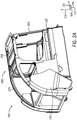
- FIG. 2A is a perspective view of an embodiment of a protection system 200 that may be used on the work vehicle 100 of FIG. 1 .
- the protection system 200 includes the rear portion 275 rigidly and non-rotatably coupled to the chassis 110 and the top portion 250 rigidly and non-rotatably coupled to the cab 120.
- the protection system may include multiple rear portions 275 and/or multiple top portions 250.
- other embodiments may include only the rear portion 275 or only the top portion 250.
- the rear portion 275 and the top portion 250 are separate from one another.
- the protection system 200 enables the cab 120 to rotate about the lateral axis 114 in pitch 117 via a pin joint 122.
- the protection system 200 is configured to block falling objects from impacting the cab 120 and/or the chassis 110.
- the top portion 250 and the rear portion 275 include members disposed above the cab 120 and the chassis 110.
- FIG. 2B is a perspective view of the protection system 200 of FIG. 2A , in which the rear portion 275 is coupled to the chassis 110 of the work vehicle 100.
- a vertical structural member 203 extends substantially along the vertical axis 113 (i.e. at an angle 30 degrees or less with respect to the vertical axis 113) and couples to a curved structural member 201 (e.g., by bolts or welds).
- the curved structural member 201 may include a straight structural member, or multiple straight structural members.
- an outer panel 202 couples (e.g., by bolts or welds) to both the vertical structural member 203 and the curved structural member 201.
- the vertical structural member 203 and the curved structural member 201 may be a single member in certain embodiments.
- the outer panel 202 is coupled to the vertical structural member 203 by bolts 204, and the outer panel 202 is coupled to the curved structural member by bolts 206.
- the rear portion 275 is coupled to the chassis 110 on one end by bolts 206 that pass through the curved structural member 201 and the outer panel 202.
- the rear portion 275 is coupled to the chassis 110 at the other end by welding the vertical structural member 203 and/or the outer panel 202 to the chassis 110.
- the rear portion 275 may be coupled to the chassis 110 by any suitable coupling system, such as welding.
- the bolts 204 couple the outer panel 202 to the vertical structural member 203; however, the bolts 204 may also pass through a portion of the chassis 110, thereby coupling the outer panel 202 and the vertical structural member 203 to the chassis 110.
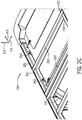
- FIG. 2C is a perspective view of the protection system 200 of FIG. 2A , in which the top portion 250 is coupled to the cab 120 of the work vehicle 100.
- the top portion 250 includes longitudinal structural members 251 oriented substantially along the longitudinal axis 115 and lateral structural members 252 oriented substantially along the lateral axis 114.
- substantially along an axis refers to an angle relative to the respective axis of between 0 degrees and 45 degrees, between 0 degrees and 30 degrees, between 0 degrees and 15 degrees, between 0 degrees and 5 degrees, or between 0 degrees and 2 degrees.
- the angle between the element and the axis may be less than 5 degrees, less than 4 degrees, less than 3 degrees, less than 2 degrees, or less than 1 degree.
- the top portion 250 may include any suitable number of lateral structural members 252 (e.g., 1, 2, 3, 4, 5, 6, or more) extending substantially along the lateral axis 114.
- the illustrated embodiment includes four longitudinal structural members 251 extending substantially along the longitudinal axis 115, it should be appreciated that the top portion 250 may include any suitable number of members (e.g., 1, 2, 3, 4, 5, 6, or more) extending substantially along the longitudinal axis 115.
- the present embodiment includes longitudinal structural members 251 and lateral structural members 252 at approximately 90 degrees relative to one another, it should be appreciated that the longitudinal structural members 251 and the lateral structural members 252 may be at any suitable angle relative to one another, including 5 degrees, 10 degrees, 20 degrees, 30 degrees, 40 degrees, 50 degrees, 60 degrees, 70 degrees, 80 degrees, 90 degrees, or any suitable angle in between.
- the top portion 250 is coupled to the cab 120 at the longitudinal structural members 251 by fasteners 253.
- fastening systems e.g., welding
- alternative embodiments e.g., in addition or as an alternative to the fasteners 253.
- lateral structural members 252 are coupled to longitudinal structural members 251 by welding, but other fastening systems may be used (e.g., fasteners 253) in alternative embodiments. Alternative embodiments may also include more or fewer fasteners (e.g., 1, 2, 3, 4, 5, 6, or more).
- FIG. 2D is a perspective view of the protection system of FIG. 2A , in which light assemblies 254 are coupled to a frame 241 of the top portion 250, and an overhang 259 extends over a lighting system 260.
- light assemblies 254 are coupled to the frame 241 of the top portion 250 via respective brackets 258 and fasteners 256.
- the frame 241 is formed by the longitudinal structural members 251 and the lateral structural members 252 described above.
- each light assembly 254 includes a wiring assembly 257 that electrically couples a respective light 255 to a power source, such as a battery, a generator, or any other suitable type of power source.
- a power source such as a battery, a generator, or any other suitable type of power source.
- the top portion 250 may include more or fewer light assemblies (e.g., 1, 2, 3, 4, 5, 6, or more).
- the work vehicle 100 may operate in low light conditions. Work vehicles 100 operating under these conditions may benefit from light assemblies 254 illuminating the area around the work vehicle 100. Further, the light assemblies 254 may make the work vehicle 100 more visible in low light conditions.
- the top portion 250 also includes an overhang 259 disposed above a lighting system 260 relative to the ground surface.
- the overhang 259 is positioned at one longitudinal end of the top portion 250; however, it should be appreciated that, in alternative embodiments, the overhang 259 may be positioned over some or all of the top portion 250.
- the overhang 259 may block falling objects from impacting the lighting system 260.
- the overhang 259 may block falling objects from impacting some or all of the light assemblies 254.
- the overhang 259 may couple to the frame 241 by any suitable connection (e.g., by bolts or welds).
- the overhang 259 may couple to the cab 120 by any suitable connection (e.g., by bolts or welds). Further, the overhang 259 may be omitted in certain embodiments.
- FIG. 2E is a top view of the protection system 200 of FIG. 2A .
- the rear portion 275 includes lateral structural members 205 oriented substantially along the lateral axis 114.
- the lateral structural members 205 are coupled to the curved structural members 201.
- the lateral structural members 205 may be coupled to the curved structural members 201 by any suitable connection, including welds and/or bolts. It should be noted that, in alternative embodiments, the lateral structural members 205 may couple to other parts of the rear portion 275, including the vertical structural members 203.
- the present embodiment includes two lateral structural members 205, but other embodiments may include any suitable number of lateral structural members 205 (e.g., 1, 2, 3, 4, 5, 6, or more).
- the frame 210 is formed by combination of the lateral structural members 205, the vertical structural members 203, the curved structural members 201, and the outer panel 202.
- the curved structural members 201, the vertical structural members 203, and the lateral structural members 205 are tubes; however, it should be appreciated that the structural members may include any suitable structure, including plates and bars, among other elements.
- the bolts 204 and the bolts 206 are disposed at opposite longitudinal sides of the rear portion 275.
- the two sets of bolts 204 are disposed at opposite lateral sides of the rear portion 275, and the two sets of bolts 206 are disposed at opposite lateral sides of the rear portion 275.
- the bolts 204 in addition to welds, couple the vertical structural members 203 to the outer panels 202.
- the bolts 206 couple the curved structural member 201, the outer panel 202, and the chassis 110 one another.
- the top portion 250 includes the longitudinal structural members 251, the lateral structural members 252, and the overhang 259.
- the longitudinal structural members 251 and the lateral structural members are tubes; however, it should be appreciated that the structural members may include any suitable structure, including plates and bars, among other elements.
- the rear portion 275 and the top portion 250 are separate from one other by a gap 300.
- the gap 300 extends substantially along the lateral axis 114.
- the gap 300 enables the rear portion 275 and the top portion 250 to freely move relative to one another.
- the gap 300 enables the cab 120, which the top portion 250 is coupled to, to rotate forward about the lateral axis 114 without decoupling of the rear portion 275 and the top portion 250.
- the width 301 of the gap 300 may be any suitable distance, including 1 centimeters ("cm"), 2 cm, 5 cm, or 10 cm, or more.
- the width 301 may or may not be constant across the lateral length of the gap 300.
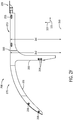
- FIG. 2F is a side view of the protection system of FIG. 2A .
- a first height 352 of a maximum vertical extent of the rear portion 275 with respect to a ground surface 350 is substantially equal to a second height 351 of a maximum vertical extent of the top portion 250 with respect to the ground surface 350.
- the ground surface 350 may be parallel to a plane formed by the lateral axis 114 and the longitudinal axis 115.
- substantially equal refers to a height difference of less than 1 cm, 2 cm, 5 cm, or 10 cm.
- the maximum vertical extents of the rear portion 275 and the top portion 250 have substantially equal heights 351, 352 in the illustrated embodiment, it should be appreciated that the maximum vertical extent of the rear portion 275 may be higher or lower than the maximum vertical extent of the top portion 250 in alternative embodiments.
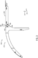
- FIG. 3 is a side view of the protection system 200 of FIG. 2A , including an embodiment of a coupling mechanism 400.
- the coupling mechanism 400 includes a pin 401, a pin 403, and a plate 402.
- the coupling mechanism 400 is configured to selectively couple the rear portion 275 to the top portion 250.
- the coupling mechanism 400 may include another suitable device, such as a latch, a lock, a clamp, among others.
- the coupling mechanism 400 may be disposed at any location along the gap 300.
- the plate 402 is coupled rotatably or non-rotatably to the rear portion 275 and/or the top portion 250.
- the pin 401 couples the plate 402 to the top portion 250, and the pin 403 couples the plate 402 to the rear portion 275.
- the pin 401 may be uncoupled from top portion 250 through user interaction, thereby uncoupling the top portion 250 from the rear portion 275.
- the pin 403 may be uncoupled from the rear portion 275 through user interaction, thereby uncoupling the top portion 250 from the rear portion 275.
- Fasteners such as the pin 401 and the pin 403, may be toolless fasteners. As such, the pin 401 and the pin 403 may be uncoupled without the use of any tools.
Landscapes
- Engineering & Computer Science (AREA)
- Mechanical Engineering (AREA)
- Transportation (AREA)
- Structural Engineering (AREA)
- Chemical & Material Sciences (AREA)
- Combustion & Propulsion (AREA)
- Civil Engineering (AREA)
- Life Sciences & Earth Sciences (AREA)
- Geology (AREA)
- Mining & Mineral Resources (AREA)
- General Engineering & Computer Science (AREA)
- Body Structure For Vehicles (AREA)
Applications Claiming Priority (1)
| Application Number | Priority Date | Filing Date | Title |
|---|---|---|---|
| US15/392,969 US10479421B2 (en) | 2016-12-28 | 2016-12-28 | Protection system for a work vehicle |
Publications (1)
| Publication Number | Publication Date |
|---|---|
| EP3342939A1 true EP3342939A1 (fr) | 2018-07-04 |
Family
ID=60781982
Family Applications (1)
| Application Number | Title | Priority Date | Filing Date |
|---|---|---|---|
| EP17209845.1A Withdrawn EP3342939A1 (fr) | 2016-12-28 | 2017-12-21 | Système de protection pour véhicule de travail |
Country Status (4)
| Country | Link |
|---|---|
| US (1) | US10479421B2 (fr) |
| EP (1) | EP3342939A1 (fr) |
| CN (1) | CN207773285U (fr) |
| BR (1) | BR102017026656B1 (fr) |
Families Citing this family (1)
| Publication number | Priority date | Publication date | Assignee | Title |
|---|---|---|---|---|
| US10538272B2 (en) * | 2017-04-17 | 2020-01-21 | Kubota Corporation | Vehicle |
Citations (7)
| Publication number | Priority date | Publication date | Assignee | Title |
|---|---|---|---|---|
| US3690720A (en) * | 1970-07-27 | 1972-09-12 | Deere & Co | Vehicle cab and safety frame assembly |
| JPH0718700A (ja) * | 1993-06-30 | 1995-01-20 | Kubota Corp | 作業機用キャノピー |
| JPH08151665A (ja) * | 1994-11-28 | 1996-06-11 | Komatsu Ltd | 運転室の保護装置 |
| EP0909855A2 (fr) * | 1997-10-17 | 1999-04-21 | Deere & Company | Véhicule chargeur |
| CN1760478A (zh) * | 2004-10-11 | 2006-04-19 | 日立建机株式会社 | 建筑机械 |
| JP2007255122A (ja) * | 2006-03-24 | 2007-10-04 | Shin Caterpillar Mitsubishi Ltd | 作業機械 |
| EP3020873A2 (fr) * | 2014-11-12 | 2016-05-18 | Echle Hartstahl GmbH | Structure de protection d'une cabine de conducteur d'une machine-outil |
Family Cites Families (10)
| Publication number | Priority date | Publication date | Assignee | Title |
|---|---|---|---|---|
| US3976323A (en) | 1973-10-23 | 1976-08-24 | Caterpillar Tractor Co. | Cab mounting structure |
| US4401179A (en) | 1981-09-04 | 1983-08-30 | J. I. Case Company | Assist assembly for cab structure |
| DE3602762A1 (de) | 1986-01-30 | 1987-08-06 | Claas Ohg | Flurfoerderzug |
| DE69800866T2 (de) * | 1998-04-17 | 2001-11-15 | Liftcon Technologies Ltd., Shannon | Transportabler Gabelhubwagen mit teleskopischem Hebearm |
| US6189955B1 (en) * | 2000-04-18 | 2001-02-20 | Deere & Company | Operator enclosure for an agricultural tractor |
| US6910731B2 (en) | 2002-12-19 | 2005-06-28 | Clark Equipment Company | Skid steer loader with front pivoting cab having a no tool latch |
| US7909389B2 (en) | 2008-01-31 | 2011-03-22 | Cnh America Llc | Protection device for a pivotable cab structure |
| US7975793B1 (en) * | 2009-01-02 | 2011-07-12 | Gehl Company | Tilting foot pod for the operator cab of a skid steer vehicle |
| GB2531762A (en) * | 2014-10-29 | 2016-05-04 | Bamford Excavators Ltd | Working machine |
| US9982413B2 (en) * | 2016-10-03 | 2018-05-29 | Cnh Industrial America Llc | Cab suspension system for a work vehicle |
-
2016
- 2016-12-28 US US15/392,969 patent/US10479421B2/en active Active
-
2017
- 2017-11-29 CN CN201721621171.1U patent/CN207773285U/zh active Active
- 2017-12-11 BR BR102017026656-7A patent/BR102017026656B1/pt active IP Right Grant
- 2017-12-21 EP EP17209845.1A patent/EP3342939A1/fr not_active Withdrawn
Patent Citations (7)
| Publication number | Priority date | Publication date | Assignee | Title |
|---|---|---|---|---|
| US3690720A (en) * | 1970-07-27 | 1972-09-12 | Deere & Co | Vehicle cab and safety frame assembly |
| JPH0718700A (ja) * | 1993-06-30 | 1995-01-20 | Kubota Corp | 作業機用キャノピー |
| JPH08151665A (ja) * | 1994-11-28 | 1996-06-11 | Komatsu Ltd | 運転室の保護装置 |
| EP0909855A2 (fr) * | 1997-10-17 | 1999-04-21 | Deere & Company | Véhicule chargeur |
| CN1760478A (zh) * | 2004-10-11 | 2006-04-19 | 日立建机株式会社 | 建筑机械 |
| JP2007255122A (ja) * | 2006-03-24 | 2007-10-04 | Shin Caterpillar Mitsubishi Ltd | 作業機械 |
| EP3020873A2 (fr) * | 2014-11-12 | 2016-05-18 | Echle Hartstahl GmbH | Structure de protection d'une cabine de conducteur d'une machine-outil |
Also Published As
| Publication number | Publication date |
|---|---|
| US10479421B2 (en) | 2019-11-19 |
| CN207773285U (zh) | 2018-08-28 |
| BR102017026656B1 (pt) | 2023-01-10 |
| US20180178857A1 (en) | 2018-06-28 |
| BR102017026656A2 (pt) | 2018-08-21 |
Similar Documents
| Publication | Publication Date | Title |
|---|---|---|
| US10947698B2 (en) | Low-profile machine cabin | |
| US9346495B2 (en) | Machine cabin having improved operator visibility | |
| EP3678892B1 (fr) | Véhicule agricole doté d'une chaîne cinématique électrique | |
| US9446658B2 (en) | Agricultural tractor front end installation | |
| CN108698649A (zh) | 具有改进的操作员可视性的机械驾驶室 | |
| EP3216749B1 (fr) | Chariot de manutention, en particulier chariot à fourche à contre-poids comprenant un dispositif de surveillance de l'espace arrière | |
| WO2023006814A1 (fr) | Système de protection contre les chocs de débris | |
| US10479421B2 (en) | Protection system for a work vehicle | |
| EP4396013B1 (fr) | Ensemble chaîne de puissance d'un engin de travail et engin de travail | |
| US20180179731A1 (en) | Platform assembly for a ground engaging tool | |
| US10399521B2 (en) | Bumper assembly for a work vehicle | |
| EP1145939A2 (fr) | Véhicule de travail et cabine de conduite | |
| US11306459B2 (en) | Accessory mounting system for a work vehicle | |
| US10099640B1 (en) | Pivoting bumper for vehicle | |
| EP4169773A1 (fr) | Dispositif d'inclinaison d'un véhicule automobile | |
| DE60313806T2 (de) | Lasthandhabungsfahrzeug | |
| US20160152142A1 (en) | Mounting structure for supporting pantograph in machine | |
| RU2815822C1 (ru) | Многофункциональное самоходное энергетическое средство | |
| EP4574488A1 (fr) | Agencement de protection contre les chocs de batterie | |
| EP1678994B1 (fr) | Tracteur à chassis | |
| JP2022101316A (ja) | 作業車 | |
| EP4467728A1 (fr) | Véhicule chenillé | |
| DE202022105090U1 (de) | Batterie-elektrischer Schlepper sowie Baukasten für seine Erstellung | |
| DE102025129243A1 (de) | Frontstruktur für ein elektrofahrzeug |
Legal Events
| Date | Code | Title | Description |
|---|---|---|---|
| PUAI | Public reference made under article 153(3) epc to a published international application that has entered the european phase |
Free format text: ORIGINAL CODE: 0009012 |
|
| STAA | Information on the status of an ep patent application or granted ep patent |
Free format text: STATUS: THE APPLICATION HAS BEEN PUBLISHED |
|
| AK | Designated contracting states |
Kind code of ref document: A1 Designated state(s): AL AT BE BG CH CY CZ DE DK EE ES FI FR GB GR HR HU IE IS IT LI LT LU LV MC MK MT NL NO PL PT RO RS SE SI SK SM TR |
|
| AX | Request for extension of the european patent |
Extension state: BA ME |
|
| STAA | Information on the status of an ep patent application or granted ep patent |
Free format text: STATUS: REQUEST FOR EXAMINATION WAS MADE |
|
| 17P | Request for examination filed |
Effective date: 20190104 |
|
| RBV | Designated contracting states (corrected) |
Designated state(s): AL AT BE BG CH CY CZ DE DK EE ES FI FR GB GR HR HU IE IS IT LI LT LU LV MC MK MT NL NO PL PT RO RS SE SI SK SM TR |
|
| STAA | Information on the status of an ep patent application or granted ep patent |
Free format text: STATUS: EXAMINATION IS IN PROGRESS |
|
| 17Q | First examination report despatched |
Effective date: 20211026 |
|
| STAA | Information on the status of an ep patent application or granted ep patent |
Free format text: STATUS: THE APPLICATION IS DEEMED TO BE WITHDRAWN |
|
| 18D | Application deemed to be withdrawn |
Effective date: 20220308 |